Difference between revisions of "F21: Treasure Dive"
Proj user1 (talk | contribs) |
Proj user1 (talk | contribs) (→Conclusion) |
||
| (103 intermediate revisions by the same user not shown) | |||
| Line 1: | Line 1: | ||
| − | |||
| − | |||
| − | |||
| − | |||
| − | |||
| − | |||
| − | |||
| − | |||
| − | |||
| − | |||
| − | |||
| − | |||
| − | |||
| − | |||
| − | |||
| − | |||
| − | |||
== '''Treasure Dive''' == | == '''Treasure Dive''' == | ||
| + | [[File:mermaid.png|thumb|500px|right|Game Screen Capture]] | ||
| + | [[File:Cmpe-244-controller-pic.png|thumb|600px|right|Game Controller]] | ||
== Abstract == | == Abstract == | ||
| − | Treasure Dive is a modern one player game inspired by the popular arcade game Breakout, which was released by Atari in 1976. The ancients rambled about an unconfirmed tale of a shipwreck that saw no survivors. As an adventurous and skilled free diver, you are seeking treasure buried deep in an ocean abyss. You dove down all the way to the seafloor and found the buried treasure but need to make it back to the surface to see another day! The player uses a wireless controller to control an on-screen paddle to break bricks on the top of the screen. When enough bricks are broken, a passage is revealed, allowing you to get closer to the surface. | + | Treasure Dive is a modern one player game inspired by the popular arcade game Breakout, which was released by Atari in 1976. The ancients rambled about an unconfirmed tale of a shipwreck that saw no survivors. As an adventurous and skilled free diver, you are seeking the lost treasure buried deep in an ocean abyss. You dove down all the way to the seafloor and found the buried treasure but need to make it back to the surface to see another day! The player uses a wireless controller to control an on-screen paddle to break bricks on the top of the screen. When enough bricks are broken, a passage is revealed, allowing you to get closer to the surface. |
== Objectives & Introduction == | == Objectives & Introduction == | ||
| − | The objective of this project is to interface an LPC4088 to a VGA monitor by leveraging the LCD controller and use an accelerometer as the sensor for the player | + | The objective of this project is to: |
| + | <br> | ||
| + | - interface an LPC4088 to a VGA monitor by leveraging the LCD controller and to use an accelerometer as the sensor for the player controller | ||
| + | <br> | ||
| + | - integrate two Zigbees RF modules integrated for wireless communication between the controller and LPC4088 board via UART protocol | ||
| + | <br> | ||
| + | - enable digital audio output by developing an I2S driver and porting an audio tracker library | ||
| + | <br> | ||
| + | - utilize the General Purpose Direct Memory Access (GPDMA) controller memory-to-memory function to decrease memory write times when updating the video buffer | ||
| + | <br> | ||
| + | - utilize the DMA controller's memory-to-peripheral function to help reduce frequent I2S interrupts when loading digital audio contents | ||
| + | <br> | ||
| + | - implement an SD card peripheral driver to facilitate memory exchange between an SD card | ||
=== Team Members & Responsibilities === | === Team Members & Responsibilities === | ||
| − | * Brian Ho | + | [[File:Cmpe-244-brian-pic.png ]] |
| + | * '''Brian Ho''' | ||
** Wiki project schedule planning | ** Wiki project schedule planning | ||
** Interfacing the accelerometer | ** Interfacing the accelerometer | ||
| Line 36: | Line 34: | ||
** Hardware/software development and integration | ** Hardware/software development and integration | ||
** Final testing and integration | ** Final testing and integration | ||
| − | * Billy Lai | + | [[File:Cmpe-244-billy-pic.png]] |
| + | * '''[https://www.linkedin.com/in/william-lai-525681139 Billy Lai]''' | ||
** Wiki project schedule planning | ** Wiki project schedule planning | ||
** Increased CPU clock rate from 96 MHz to 120 MHz | ** Increased CPU clock rate from 96 MHz to 120 MHz | ||
| Line 45: | Line 44: | ||
** Software development and integration | ** Software development and integration | ||
** Final testing and integration | ** Final testing and integration | ||
| − | * Jasdip Sekhon | + | [[File:Cmpe-244-jasdip-pic.png]] |
| + | * '''Jasdip Sekhon''' | ||
** Wiki project schedule planning | ** Wiki project schedule planning | ||
** PCB design and planning | ** PCB design and planning | ||
| Line 53: | Line 53: | ||
** Software development and integration | ** Software development and integration | ||
** Final testing and integration | ** Final testing and integration | ||
| − | * Isaac Wahhab | + | [[File:Cmpe-244-isaac-pic.png ]] |
| + | * '''Isaac Wahhab''' | ||
** Wiki project schedule planning | ** Wiki project schedule planning | ||
** DAC resistor ladder design and integration | ** DAC resistor ladder design and integration | ||
| Line 262: | Line 263: | ||
|- | |- | ||
|} | |} | ||
| − | |||
| − | |||
| − | |||
| − | |||
| − | |||
| − | |||
| − | |||
== Bill Of Materials == | == Bill Of Materials == | ||
| Line 334: | Line 328: | ||
|- | |- | ||
|} | |} | ||
| − | |||
== Design & Implementation == | == Design & Implementation == | ||
=== Hardware Design === | === Hardware Design === | ||
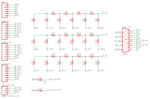
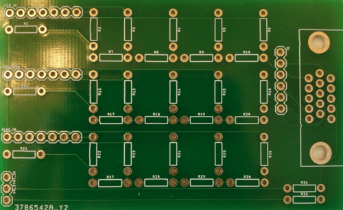
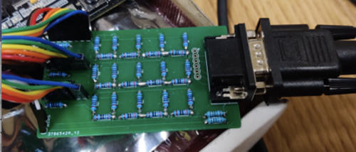
| − | We designed our PCB using Autodesk EAGLE based on the tutorial on PCB design during class lecture. We ordered our PCB to be manufactured from JLCPCB. The PCB consists of | + | We designed our PCB using Autodesk EAGLE based on the tutorial on PCB design during the class lecture. We ordered our PCB to be manufactured from JLCPCB. The PCB consists of an R-2R resistor ladder DAC for the purpose of converting the digital signal from the microcontroller to analog to display graphics on the VGA monitor. Since the VGA input for each color channel is 0-0.7V, the resistor ladder scaled the LPC4088 outputs into proper DAC values for the VGA to take in. Five bits are passed to each of the red, green, and blue channels of the VGA in addition to other signals, such as Horizontal sync (HSYNC) and Vertical sync (VSYNC). |
<br> | <br> | ||
| − | [[File:pcbSchematic.png| | + | [[File:pcbSchematic.png|500px|thumb|left|PCB Schematic]] |
| − | [[File:pcbLayout.png| | + | [[File:pcbLayout.png|500px|thumb|right|PCB Layout]] |
| − | [[File:pcbPic-min.png| | + | [[File:pcbPic-min.png|500px|thumb|right|Manufactured PCB]] |
| − | [[File:pcbManufactured.png| | + | [[File:pcbManufactured.png|500px|thumb|left|Soldered PCB]] |
<br> | <br> | ||
| + | |||
| + | |||
| + | |||
| + | |||
| + | |||
| + | |||
| + | |||
| + | |||
| + | |||
| + | |||
| + | |||
| + | |||
| + | |||
| + | |||
| + | |||
| + | |||
| + | |||
| + | |||
| + | |||
| + | |||
| + | |||
| + | |||
| + | |||
| + | |||
| + | |||
| + | |||
| + | |||
| + | |||
| + | |||
| + | |||
| + | |||
| + | |||
| + | |||
| + | |||
| + | |||
| + | |||
| + | |||
| + | |||
| + | |||
| + | |||
| + | |||
| + | |||
| + | |||
| + | |||
| + | |||
| + | |||
| + | |||
| + | |||
| + | |||
=== Hardware Interface === | === Hardware Interface === | ||
| Line 374: | Line 416: | ||
|- | |- | ||
|} | |} | ||
| + | [[File:sj2Board.png|380px|thumb|center|SJ2 Board]] | ||
[[File:CMPE146_F16_MW_XbeeModule.jpg|200px|thumb|center|XBee Device]] | [[File:CMPE146_F16_MW_XbeeModule.jpg|200px|thumb|center|XBee Device]] | ||
<br> | <br> | ||
| − | Two LED buttons were used to interface with the controller as inputs. | + | |
| + | |||
| + | |||
| + | Two LED buttons were used to interface with the controller as inputs. They were both set up using GPIO. | ||
[[File:VGA LED Button.jpg|200px|thumb|center|LED Button]] | [[File:VGA LED Button.jpg|200px|thumb|center|LED Button]] | ||
<br> | <br> | ||
| − | [[File:VGA_Controller_Block_Diagram.PNG| | + | [[File:VGA_Controller_Block_Diagram.PNG|380px|thumb|center|Controller Block Diagram]] |
<br> | <br> | ||
| + | |||
| + | |||
| + | |||
| + | ==== I2S Peripheral and Stereo Audio Decoder ==== | ||
| + | |||
| + | The LPC4088 is equipped with an I2S stereo encoder. This module provides a hardware-enabled solution for sending I2S-encoded audio data packets to stereo decoders, which produce the corresponding audio waveform. For this project, since 16-bit stereo audio playback was chosen, data packets transmitted on this interface were sent in the following format: | ||
| + | |||
| + | [[File:I2S_audio_data_word.png]] | ||
| + | |||
| + | Here, each word of data encodes a single packet of audio in two 16-bit sections: one signal level for the left channel, and another for the right. These 4 bytes are sent at a rate of 44100 Hz, resulting in a total data transmission of 176400 bytes a second. Rather than needing to be software-defined, this transmission is automatically handled by hardware using a 8-word deep FIFO queue that manages streaming out the audio data at a fixed rate, saving a significant amount of CPU cycles. | ||
| + | |||
| + | This encoded audio signal was sent to a dedicated external [https://www.nxp.com/docs/en/data-sheet/UDA1380.pdf stereo decoder], which output to a 3.5 mm audio jack connected to speakers in the VGA monitor. | ||
| + | |||
| + | ==== LCD Peripheral ==== | ||
| + | |||
| + | The LCD peripheral was configured for 16-bit color palette (5 bits of color data for each color level -- red, green, and blue -- and an unused intensity bit), at a resolution of 800 by 600 pixels, and with an active color palette size of 256 colors. Since the logic for driving an LCD display has the same concepts (horizontal blanking, vertical blanking, etc) and timing information for any given resolution was the same, we were able to directly drive a VGA display with the same signals and timing data (after the digital signal had been converted to analog). | ||
| + | |||
| + | [[File:LCD_%2B_VGA_Video_signal.png]] | ||
| + | |||
| + | The timing register configurations needed to achieve the requested video display was derived from a dedicated website for [http://tinyvga.com/vga-timing/800x600@60Hz VGA signal info]. | ||
| + | |||
| + | ==== External Memory ==== | ||
| + | |||
| + | The game's visual assets and tracker audio file (both after being loaded from an SD card) and the game's video buffer required more memory than what is present natively in the microcontroller. To accommodate this, an external 32MiB memory module was used. This module was interfaced with using the external memory controller peripheral present on the board. | ||
=== Software Design === | === Software Design === | ||
| − | + | ==== Controller ==== | |
| + | |||
| + | There is an internal accelerometer on the SJ2 board that is utilized as the movement controls for the paddle movement. The y-axis value of the magnitude is polled 17 times in 17 milliseconds and is divided by 17 to get an average reading per that time frame. The maximum tilt value that can be read by the controller is set to 700 out of the total 1000 (highest possible value). The current tilt value is divided by 31 to get a total of 32 possible readings to represent 5 bits of magnitude. | ||
| + | |||
| + | The controller sends one byte of data to the console whenever there is any change in magnitude on the accelerometer or button changes. The byte contains all the information needed to control the paddle on the screen. The first two bits on the byte represent 0 if there is no button input and 1 if there is a button input. The third bit represents whether the controller is tilted left or right with 0 being left and 1 being right. The last five bits represent the controller accelerometer's magnitude. | ||
| + | |||
| + | [[File:VGA_UART_Frame.PNG]] | ||
| + | |||
| + | ==== Audio ==== | ||
| + | |||
| + | Sound design was provided to the project (in the form of music and sound effects) through the use of a [https://https://en.wikipedia.org/wiki/Music_tracker tracker audio library]. Source code was adopted from the [https://github.com/schismtracker/schismtracker Schism Tracker] library and altered with the following modifications: | ||
| + | |||
| + | - All UI logic was stripped from the source code | ||
| + | |||
| + | - All file handling logic was reworked to use the SD card reading functions, as the project does not support POSIX file calls | ||
| + | |||
| + | - The [https://www.libsdl.org/ Simple DirectMedia Layer] hooks were replaced with a FreeRTOS task that periodically called the waveform generation callback function, which was passed to the I2S peripheral hooked up to a stereo decoder. | ||
=== Implementation === | === Implementation === | ||
| − | + | ||
| + | ==== Ball Logic ==== | ||
| + | |||
| + | The ball is controlled by the buttons and the controller accelerometer values. When the button is pressed, the ball is initially sent with a random velocity. The velocity is determined by a substate timer and is initially set as one of 6 possible values. | ||
| + | |||
| + | {| class="wikitable" | ||
| + | |- | ||
| + | ! scope="col"| Substate Count | ||
| + | ! scope="col"| X-Velocity | ||
| + | ! scope="col"| Y-Velocity | ||
| + | |- | ||
| + | ! scope="row"| 0 | ||
| + | | 4 | ||
| + | | -2 | ||
| + | |- | ||
| + | ! scope="row"| 1 | ||
| + | | -4 | ||
| + | | -2 | ||
| + | |- | ||
| + | ! scope="row"| 2 | ||
| + | | 2 | ||
| + | | -4 | ||
| + | |- | ||
| + | ! scope="row"| 3 | ||
| + | | -2 | ||
| + | | -4 | ||
| + | |- | ||
| + | ! scope="row"| 4 | ||
| + | | 1 | ||
| + | | -5 | ||
| + | |- | ||
| + | ! scope="row"| 5 | ||
| + | | -1 | ||
| + | | -5 | ||
| + | |- | ||
| + | |} | ||
| + | |||
| + | The ball's velocity changes whenever it detects a collision with either the side of the screen, the bricks on the top of the level, or the paddle at the bottom. If colliding with the paddle, the ball's velocity will take into account the paddle's velocity and add it to its current velocity. This is done by adding the paddle's x-velocity and adjusting the y-velocity by normalizing the velocity vectors to have a magnitude of 5. This means the ball will always be moving with a magnitude of 5 in any direction after it hits the paddle. If the ball collides with anything other than the paddle, then the velocity of the ball is changed with no increase or decrease of magnitude. If the ball collides on the side of a wall or block, the x-velocity will reflect (go from negative to positive or vice-versa) and the y-velocity will remain constant. If the ball collides on the top or bottom of a block, the y-velocity will reflect and the x-velocity will remain constant. If it appears that the ball collides with the side and top or bottom of something, then the ball will check whichever face it will collide with first and then calculate the other face. Lastly, when the ball collides with the bottom of the screen, then the player experiences a "death" and the ball will reset on the paddle. If the ball collides with the top of the screen, the screen will scroll up for the user to play on the next level. | ||
| + | |||
| + | Whenever the ball collides with a brick, the brick will disappear. To accomplish this, there is a 2-D array of unsigned integers that contains the values of the bricks. If the integer is 0, then there is no block. If the integer is any value other than 0, then the block is filled and has collision logic. If the ball approaches a region that might have a block, then there will be a check within that 2-D to see if the block is filled or empty. If the block is filled, there will be the collision logic that changes the vector of the ball and sets the integer value in the 2-D array to 0 to represent that the block has been broken. | ||
| + | |||
| + | ==== Paddle Movement ==== | ||
| + | The paddle movement is controlled by the accelerometer data being wirelessly transmitted from the SJ-Two board to the LPC4088 board. The accelerometer data will map to 63 possible indexes for the paddle location. Originally, the paddle would jump directly into the corresponding index location depending on the accelerometer input. We later iterated on this process by implementing an algorithm to smoothly transition into these indexes. This was done by calculating a paddle velocity using the "current desired paddle position" and the previous paddle position. We adjusted the parameters of the algorithm iteratively to produce the smooth paddle movement. | ||
| + | |||
| + | ==== Paddle Collision Logic ==== | ||
| + | The position of the ball is calculated by adding delta_x and delta_y to the ball's current x and y position. For each frame, if the ball's next Y position crosses the paddle's Y position, we would check for a paddle collision. To do this, we used the delta_x and delta_y to get the ball's movement as a slope. We then substituted the slope, the ball's current position, and 1 pixel above the paddle's Y position into a point-slope equation (y2 - y1) = m(x2 - x1) to get the paddle's X position at the time of the ball reaching the pixel above paddle's Y position. After finding the location where the ball is expected to collide with the paddle, we then calculated the ball's collision magnitude and the ball's next location's magnitude. Using a ratio of these two magnitudes, we have a frame time fraction of when the ball possibly collided with the paddle. Then, by using the paddle's current position and paddle velocity, we are able to find where the paddle previously was, and measure how far the paddle had moved during that time frame. By multiplying the time frame from the ball's collision magnitude to the paddle's change in X position, we are able to find whether the paddle was under the ball at the time of the ball reaching the pixel above the paddle's Y position. | ||
== Testing & Technical Challenges == | == Testing & Technical Challenges == | ||
| − | + | === VGA Interfacing === | |
| − | + | A DAC resistor ladder was designed and a corresponding custom PCB was acquired to interface the 3.3V digital LCD controller signal with the analog VGA input signal. The VGA cable takes between 0V (completely dark) and 0.7V (maximum brightness) for color pin inputs. The DAC resistor ladder was designed and implemented on a breadboard to verify the design. Validating the design on a breadboard gave us a clear vision during PCB design and planning. | |
| + | |||
| + | === VGA Write Timings === | ||
| + | There were initial tests that were required to be done to see if using a VGA monitor as an output was a viable option for this project. We had to test memory write timings to see if they were fast enough to match the refresh rate of the monitor. Those tests would decide how much of the screen buffer we could write to during the blanking periods during the VGA refresh. This was a good learning experience for testing hardware capabilities and should be done whenever introducing any new aspects to a project. | ||
| + | |||
| + | === Ball Collision Logic === | ||
| + | The initial version of the ball collision used pixel values to see if the ball was entering the brick. The problem was that this logic did not account for the case where the ball enters the brick diagonally and the logic for that version of the collision had to be scrapped. The later iteration of the logic was changed to checking whether the ball was potentially crossing into an area that had a brick. This was done by separating the checks into a grid that represented the locations of the blocks. In this case, there was an initial check to see if the ball was crossing a boundary where there might be a new brick. If the ball is crossing the x-boundary and not the y-boundary, then there would be a collision check to see if it collided with a block. If it is crossing the y-boundary and not the x-boundary, once again then there would be a collision check to see if it collided with a block. If it is crossing both the x-boundary and y-boundary, then there would be a check to see which boundary the ball would cross first. This new logic allowed for us to account for the case where the block enters the block diagonally. This taught us that sometimes it is beneficial to scrap a previous iteration and use a new approach to solving a problem because it may lead to better results. | ||
| − | + | === Paddle Movement === | |
| + | One issue we discovered was the paddle would slow down as it approached the walls. This was due to the difference in "current desired paddle position" and the previous paddle position becoming smaller as the walls were approached, leading to a smaller paddle velocity. To account for this, whenever the accelerometer sent data that mapped to the minimum or maximum paddle index, we would increase the distance of the "current desired paddle position" so the paddle velocity would not slow the paddle down as it approached the walls. | ||
| − | === | + | === Paddle Collision Logic === |
| − | + | During final integration and testing, one of the biggest issues we encountered was a bug where the ball would not detect a collision with the paddle. The ball would phase right through the paddle instead of bouncing off of it. One of the great ideas that we thought of was to change the color of the ball during each check to see if the checks would go through. This debug check allowed us to verify that section of code that checked for paddle collisions was being skipped even though the ball's next Y position had crossed the paddle's Y position. By having this debugging method, we were able to root cause the issue. | |
== Conclusion == | == Conclusion == | ||
| − | + | For some of us, this was our first experience in designing and implementing a functional embedded system using FreeRTOS. The challenges we hurdled to accomplish our technical goals helped to shape a journey that was greatly enhanced by the opportunity to meet in person and having a hands-on approach to hardware and component integration. We were able to utilize design principles and implement communication protocols we learned in lecture to pull this project together. Some useful topics include: UART, SPI, I2C, I2S, DMA, FreeRTOS mutexes and binary semaphores, queues, task creation, stack size, task scheduler, interrupt service routines, bootloaders, etc. After extensive hours spent testing and verifying our implementation, we have learned that time allocated for integration and testing will significantly improve chances of a successful project. If we had skipped out on testing and verification, the project could have possibly crashed and burned when it was delivered. We hope this project can be of use to any future engineers following behind us, and we wish you all good times and happy development ahead! | |
=== Project Video === | === Project Video === | ||
| − | + | [https://www.youtube.com/watch?v=ipngAGlN86c SJSU CMPE 244 FALL 2021: Embedded Software Project Gameplay] | |
=== Project Source Code === | === Project Source Code === | ||
| − | * [https:// | + | * [https://gitlab.com/fayek.wahhab/sjtwo-c/-/tree/feature/i2s_dma2 Treasure Dive Baseline for Demo Source Code] |
| + | * [https://gitlab.com/hobriandh/sjtwo-c/-/tree/final_controller Controller for Demo Source Code] | ||
| + | |||
| + | === Project Presentation === | ||
| + | * [https://docs.google.com/presentation/d/1pIAAq51RySaZrniwJGuuHpVVPT1xaE4mjnMTCl6fnXA/edit?usp=sharing Treasure Dive Demo Presentation] | ||
== References == | == References == | ||
=== Acknowledgement === | === Acknowledgement === | ||
| − | + | We would like to acknowledge and thank our instructor Preetpal Kang for sharing his knowledge in embedded software development using FreeRTOS. | |
| + | <br> | ||
| + | Another shoutout to our art designer Jacob for the unique artwork displayed in our game. | ||
| − | === | + | === Appendix === |
*[https://gitlab.com/sjtwo-c-dev/sjtwo-c/-/blob/master/LPC408X_7X%20User%20Manual.pdf LPC408x/407x Datasheet] | *[https://gitlab.com/sjtwo-c-dev/sjtwo-c/-/blob/master/LPC408X_7X%20User%20Manual.pdf LPC408x/407x Datasheet] | ||
*[https://www.freertos.org/Documentation/RTOS_book.html FreeRTOS Documentation] | *[https://www.freertos.org/Documentation/RTOS_book.html FreeRTOS Documentation] | ||
*[http://elm-chan.org/fsw/ff/00index_e.html FatFs - Generic FAT Filesystem Module] | *[http://elm-chan.org/fsw/ff/00index_e.html FatFs - Generic FAT Filesystem Module] | ||
*[https://www.digi.com/resources/library/data-sheets/ds_xbeemultipointmodules Xbee Datasheet] | *[https://www.digi.com/resources/library/data-sheets/ds_xbeemultipointmodules Xbee Datasheet] | ||
| − | + | *[http://books.socialledge.com/books/embedded-drivers-real-time-operating-systems Embedded Drivers & Real Time Operating Systems Lessons] | |
| − | |||
| − | |||
Latest revision as of 13:18, 18 December 2021
Contents
Treasure Dive
Abstract
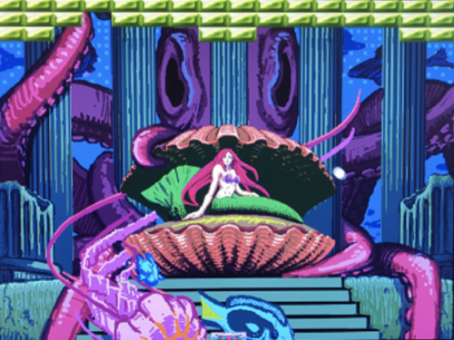
Treasure Dive is a modern one player game inspired by the popular arcade game Breakout, which was released by Atari in 1976. The ancients rambled about an unconfirmed tale of a shipwreck that saw no survivors. As an adventurous and skilled free diver, you are seeking the lost treasure buried deep in an ocean abyss. You dove down all the way to the seafloor and found the buried treasure but need to make it back to the surface to see another day! The player uses a wireless controller to control an on-screen paddle to break bricks on the top of the screen. When enough bricks are broken, a passage is revealed, allowing you to get closer to the surface.
Objectives & Introduction
The objective of this project is to:
- interface an LPC4088 to a VGA monitor by leveraging the LCD controller and to use an accelerometer as the sensor for the player controller
- integrate two Zigbees RF modules integrated for wireless communication between the controller and LPC4088 board via UART protocol
- enable digital audio output by developing an I2S driver and porting an audio tracker library
- utilize the General Purpose Direct Memory Access (GPDMA) controller memory-to-memory function to decrease memory write times when updating the video buffer
- utilize the DMA controller's memory-to-peripheral function to help reduce frequent I2S interrupts when loading digital audio contents
- implement an SD card peripheral driver to facilitate memory exchange between an SD card
Team Members & Responsibilities
- Brian Ho
- Wiki project schedule planning
- Interfacing the accelerometer
- Digital to Analog Conversion resistor ladder design used to interface digital LCD controller signal with analog VGA port signal
- PCB planning and acquisition
- Procurement of controller hardware
- Wireless communication via Zigbees RF modules and UART protocol
- Wireless controller logic and integration
- Ball movement and wall/brick collision logic
- Hardware/software development and integration
- Final testing and integration
- Billy Lai
- Wiki project schedule planning
- Increased CPU clock rate from 96 MHz to 120 MHz
- Initial memory write timing and measurements to estimate memory write capacity
- DMA driver memory-to-memory implementation for transferring graphics data to video buffer
- I2S with DMA memory-to-peripheral implementation to reduce memory-write interrupts when I2S Tx FIFO level is low
- Paddle movement and paddle collision logic, testing and integration
- Software development and integration
- Final testing and integration
- Jasdip Sekhon
- Wiki project schedule planning
- PCB design and planning
- File loading method algorithm for storing loaded files in memory
- Audio track and audio effects selection for gameplay audio
- Palette manipulation for gameplay
- Software development and integration
- Final testing and integration
- Isaac Wahhab
- Wiki project schedule planning
- DAC resistor ladder design and integration
- Hardware procurement (LPC4088 board, Zigbees, VGA monitor, etc)
- VGA driving through LCD controller
- Audio tracker library port
- Digital audio output using I2S
- Palette scrolling feature implementation
- Graphics rendering
- Vertical scrolling implementation for the video buffer
- Sprite testing and implementation for the ball
- SD card peripheral driver for reading assets from SD card
- Art assets acquisition
- Hardware/software development and integration
- Gameplay logic design
- Gameplay audio and level design
- Final testing and integration
Schedule
| Week# | Start Date | End Date | Task | Status |
|---|---|---|---|---|
| 1 |
|
|
|
|
| 2 |
|
|
|
|
| 3 |
|
|
|
|
| 4 |
|
|
|
|
| 5 |
|
|
|
|
| 6 |
|
|
|
|
| 7 |
|
|
|
|
| 8 |
|
|
|
|
| 9 |
|
|
|
|
| 10 |
|
|
|
|
| 11 |
|
|
|
|
| 12 |
|
|
|
|
Bill Of Materials
| Item# | Part Description | Part Model & Vendor | Quantity | Cost |
|---|---|---|---|---|
| 1 | Microcontroller Board | LPC4088-32 Developer's Kit | 1 | $300.00 |
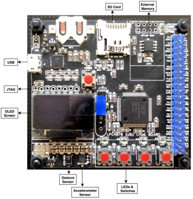
| 2 | Microcontroller Board | SJ2 Board | 1 | $50.00 |
| 3 | Bluetooth Module | Digi XBee-S1 | 2 | N/A |
| 4 | DAC PCB | JLCPCB (Set of 5) | 1 | $15.00 |
| 4 | Monitor | Asus TFT Monitor | 1 | N/A |
| 5 | Mini Breadboard | ELEGOO Mini Breadboard | 1 | $13.99 |
| 6 | Arcade buttons | EG STARTS LED Arcade Buttons | 2 | $11.99 |
| 7 | VGA cable | N/A | 1 | N/A |
| 7 | SD card | N/A | 1 | N/A |
Design & Implementation
Hardware Design
We designed our PCB using Autodesk EAGLE based on the tutorial on PCB design during the class lecture. We ordered our PCB to be manufactured from JLCPCB. The PCB consists of an R-2R resistor ladder DAC for the purpose of converting the digital signal from the microcontroller to analog to display graphics on the VGA monitor. Since the VGA input for each color channel is 0-0.7V, the resistor ladder scaled the LPC4088 outputs into proper DAC values for the VGA to take in. Five bits are passed to each of the red, green, and blue channels of the VGA in addition to other signals, such as Horizontal sync (HSYNC) and Vertical sync (VSYNC).
Hardware Interface
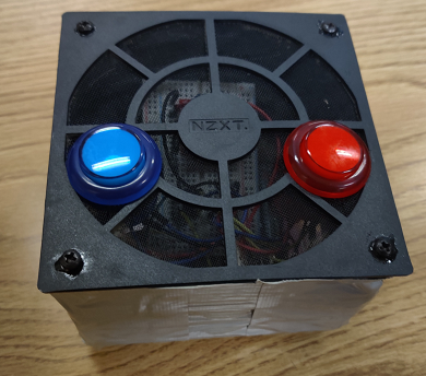
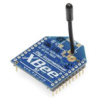
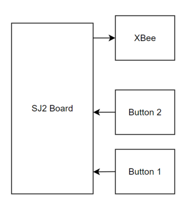
Two Digi XBee devices were used to communicate between the SJ2-Board controller and the LPC4088 board to control the paddle on the game. The XBee devices were programmed using the XTCU programming application provided by Digi International. The SJ2-Board used one XBee as a transmitted and the LPC4088 used another as a receiver. The two modules communicated using UART frames and a single byte represented any change of movement or button presses sent by the controller.
| XCTU | Transmitter | Receiver |
|---|---|---|
| CH | C | C |
| ID | 6969 | 6969 |
| CE | Coordinator | Endpoint |
| Baud Rate | 9600 | 9600 |
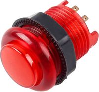
Two LED buttons were used to interface with the controller as inputs. They were both set up using GPIO.
I2S Peripheral and Stereo Audio Decoder
The LPC4088 is equipped with an I2S stereo encoder. This module provides a hardware-enabled solution for sending I2S-encoded audio data packets to stereo decoders, which produce the corresponding audio waveform. For this project, since 16-bit stereo audio playback was chosen, data packets transmitted on this interface were sent in the following format:
Here, each word of data encodes a single packet of audio in two 16-bit sections: one signal level for the left channel, and another for the right. These 4 bytes are sent at a rate of 44100 Hz, resulting in a total data transmission of 176400 bytes a second. Rather than needing to be software-defined, this transmission is automatically handled by hardware using a 8-word deep FIFO queue that manages streaming out the audio data at a fixed rate, saving a significant amount of CPU cycles.
This encoded audio signal was sent to a dedicated external stereo decoder, which output to a 3.5 mm audio jack connected to speakers in the VGA monitor.
LCD Peripheral
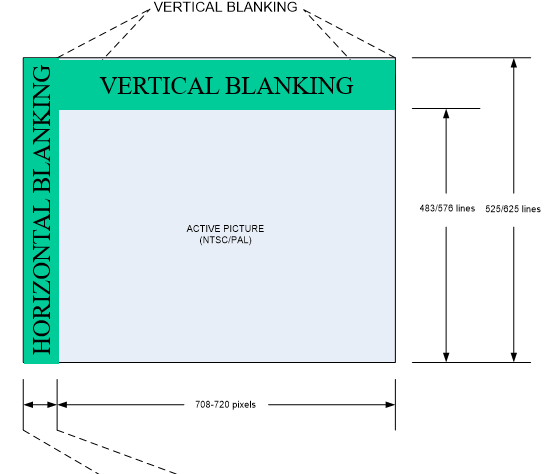
The LCD peripheral was configured for 16-bit color palette (5 bits of color data for each color level -- red, green, and blue -- and an unused intensity bit), at a resolution of 800 by 600 pixels, and with an active color palette size of 256 colors. Since the logic for driving an LCD display has the same concepts (horizontal blanking, vertical blanking, etc) and timing information for any given resolution was the same, we were able to directly drive a VGA display with the same signals and timing data (after the digital signal had been converted to analog).
The timing register configurations needed to achieve the requested video display was derived from a dedicated website for VGA signal info.
External Memory
The game's visual assets and tracker audio file (both after being loaded from an SD card) and the game's video buffer required more memory than what is present natively in the microcontroller. To accommodate this, an external 32MiB memory module was used. This module was interfaced with using the external memory controller peripheral present on the board.
Software Design
Controller
There is an internal accelerometer on the SJ2 board that is utilized as the movement controls for the paddle movement. The y-axis value of the magnitude is polled 17 times in 17 milliseconds and is divided by 17 to get an average reading per that time frame. The maximum tilt value that can be read by the controller is set to 700 out of the total 1000 (highest possible value). The current tilt value is divided by 31 to get a total of 32 possible readings to represent 5 bits of magnitude.
The controller sends one byte of data to the console whenever there is any change in magnitude on the accelerometer or button changes. The byte contains all the information needed to control the paddle on the screen. The first two bits on the byte represent 0 if there is no button input and 1 if there is a button input. The third bit represents whether the controller is tilted left or right with 0 being left and 1 being right. The last five bits represent the controller accelerometer's magnitude.
Audio
Sound design was provided to the project (in the form of music and sound effects) through the use of a tracker audio library. Source code was adopted from the Schism Tracker library and altered with the following modifications:
- All UI logic was stripped from the source code
- All file handling logic was reworked to use the SD card reading functions, as the project does not support POSIX file calls
- The Simple DirectMedia Layer hooks were replaced with a FreeRTOS task that periodically called the waveform generation callback function, which was passed to the I2S peripheral hooked up to a stereo decoder.
Implementation
Ball Logic
The ball is controlled by the buttons and the controller accelerometer values. When the button is pressed, the ball is initially sent with a random velocity. The velocity is determined by a substate timer and is initially set as one of 6 possible values.
| Substate Count | X-Velocity | Y-Velocity |
|---|---|---|
| 0 | 4 | -2 |
| 1 | -4 | -2 |
| 2 | 2 | -4 |
| 3 | -2 | -4 |
| 4 | 1 | -5 |
| 5 | -1 | -5 |
The ball's velocity changes whenever it detects a collision with either the side of the screen, the bricks on the top of the level, or the paddle at the bottom. If colliding with the paddle, the ball's velocity will take into account the paddle's velocity and add it to its current velocity. This is done by adding the paddle's x-velocity and adjusting the y-velocity by normalizing the velocity vectors to have a magnitude of 5. This means the ball will always be moving with a magnitude of 5 in any direction after it hits the paddle. If the ball collides with anything other than the paddle, then the velocity of the ball is changed with no increase or decrease of magnitude. If the ball collides on the side of a wall or block, the x-velocity will reflect (go from negative to positive or vice-versa) and the y-velocity will remain constant. If the ball collides on the top or bottom of a block, the y-velocity will reflect and the x-velocity will remain constant. If it appears that the ball collides with the side and top or bottom of something, then the ball will check whichever face it will collide with first and then calculate the other face. Lastly, when the ball collides with the bottom of the screen, then the player experiences a "death" and the ball will reset on the paddle. If the ball collides with the top of the screen, the screen will scroll up for the user to play on the next level.
Whenever the ball collides with a brick, the brick will disappear. To accomplish this, there is a 2-D array of unsigned integers that contains the values of the bricks. If the integer is 0, then there is no block. If the integer is any value other than 0, then the block is filled and has collision logic. If the ball approaches a region that might have a block, then there will be a check within that 2-D to see if the block is filled or empty. If the block is filled, there will be the collision logic that changes the vector of the ball and sets the integer value in the 2-D array to 0 to represent that the block has been broken.
Paddle Movement
The paddle movement is controlled by the accelerometer data being wirelessly transmitted from the SJ-Two board to the LPC4088 board. The accelerometer data will map to 63 possible indexes for the paddle location. Originally, the paddle would jump directly into the corresponding index location depending on the accelerometer input. We later iterated on this process by implementing an algorithm to smoothly transition into these indexes. This was done by calculating a paddle velocity using the "current desired paddle position" and the previous paddle position. We adjusted the parameters of the algorithm iteratively to produce the smooth paddle movement.
Paddle Collision Logic
The position of the ball is calculated by adding delta_x and delta_y to the ball's current x and y position. For each frame, if the ball's next Y position crosses the paddle's Y position, we would check for a paddle collision. To do this, we used the delta_x and delta_y to get the ball's movement as a slope. We then substituted the slope, the ball's current position, and 1 pixel above the paddle's Y position into a point-slope equation (y2 - y1) = m(x2 - x1) to get the paddle's X position at the time of the ball reaching the pixel above paddle's Y position. After finding the location where the ball is expected to collide with the paddle, we then calculated the ball's collision magnitude and the ball's next location's magnitude. Using a ratio of these two magnitudes, we have a frame time fraction of when the ball possibly collided with the paddle. Then, by using the paddle's current position and paddle velocity, we are able to find where the paddle previously was, and measure how far the paddle had moved during that time frame. By multiplying the time frame from the ball's collision magnitude to the paddle's change in X position, we are able to find whether the paddle was under the ball at the time of the ball reaching the pixel above the paddle's Y position.
Testing & Technical Challenges
VGA Interfacing
A DAC resistor ladder was designed and a corresponding custom PCB was acquired to interface the 3.3V digital LCD controller signal with the analog VGA input signal. The VGA cable takes between 0V (completely dark) and 0.7V (maximum brightness) for color pin inputs. The DAC resistor ladder was designed and implemented on a breadboard to verify the design. Validating the design on a breadboard gave us a clear vision during PCB design and planning.
VGA Write Timings
There were initial tests that were required to be done to see if using a VGA monitor as an output was a viable option for this project. We had to test memory write timings to see if they were fast enough to match the refresh rate of the monitor. Those tests would decide how much of the screen buffer we could write to during the blanking periods during the VGA refresh. This was a good learning experience for testing hardware capabilities and should be done whenever introducing any new aspects to a project.
Ball Collision Logic
The initial version of the ball collision used pixel values to see if the ball was entering the brick. The problem was that this logic did not account for the case where the ball enters the brick diagonally and the logic for that version of the collision had to be scrapped. The later iteration of the logic was changed to checking whether the ball was potentially crossing into an area that had a brick. This was done by separating the checks into a grid that represented the locations of the blocks. In this case, there was an initial check to see if the ball was crossing a boundary where there might be a new brick. If the ball is crossing the x-boundary and not the y-boundary, then there would be a collision check to see if it collided with a block. If it is crossing the y-boundary and not the x-boundary, once again then there would be a collision check to see if it collided with a block. If it is crossing both the x-boundary and y-boundary, then there would be a check to see which boundary the ball would cross first. This new logic allowed for us to account for the case where the block enters the block diagonally. This taught us that sometimes it is beneficial to scrap a previous iteration and use a new approach to solving a problem because it may lead to better results.
Paddle Movement
One issue we discovered was the paddle would slow down as it approached the walls. This was due to the difference in "current desired paddle position" and the previous paddle position becoming smaller as the walls were approached, leading to a smaller paddle velocity. To account for this, whenever the accelerometer sent data that mapped to the minimum or maximum paddle index, we would increase the distance of the "current desired paddle position" so the paddle velocity would not slow the paddle down as it approached the walls.
Paddle Collision Logic
During final integration and testing, one of the biggest issues we encountered was a bug where the ball would not detect a collision with the paddle. The ball would phase right through the paddle instead of bouncing off of it. One of the great ideas that we thought of was to change the color of the ball during each check to see if the checks would go through. This debug check allowed us to verify that section of code that checked for paddle collisions was being skipped even though the ball's next Y position had crossed the paddle's Y position. By having this debugging method, we were able to root cause the issue.
Conclusion
For some of us, this was our first experience in designing and implementing a functional embedded system using FreeRTOS. The challenges we hurdled to accomplish our technical goals helped to shape a journey that was greatly enhanced by the opportunity to meet in person and having a hands-on approach to hardware and component integration. We were able to utilize design principles and implement communication protocols we learned in lecture to pull this project together. Some useful topics include: UART, SPI, I2C, I2S, DMA, FreeRTOS mutexes and binary semaphores, queues, task creation, stack size, task scheduler, interrupt service routines, bootloaders, etc. After extensive hours spent testing and verifying our implementation, we have learned that time allocated for integration and testing will significantly improve chances of a successful project. If we had skipped out on testing and verification, the project could have possibly crashed and burned when it was delivered. We hope this project can be of use to any future engineers following behind us, and we wish you all good times and happy development ahead!
Project Video
SJSU CMPE 244 FALL 2021: Embedded Software Project Gameplay
Project Source Code
Project Presentation
References
Acknowledgement
We would like to acknowledge and thank our instructor Preetpal Kang for sharing his knowledge in embedded software development using FreeRTOS.
Another shoutout to our art designer Jacob for the unique artwork displayed in our game.
