Difference between revisions of "F21: ACE MARIO"
Proj user13 (talk | contribs) |
Proj user13 (talk | contribs) (→Objectives & Introduction) |
||
| (One intermediate revision by the same user not shown) | |||
| Line 34: | Line 34: | ||
*Last few seconds on your time span will be indicated by red battery lines, otherwise it will be green in color and is continuously diminishing the green lines as the game ascend. | *Last few seconds on your time span will be indicated by red battery lines, otherwise it will be green in color and is continuously diminishing the green lines as the game ascend. | ||
*Failure to avoid obstacles as indicated by the game restart screen reduces your lives one by one. Hence, you will have only 3 chances to stay in the game with the usage of lives. Consequently, once you land on any obstacles and you have no lives left, the game ends. | *Failure to avoid obstacles as indicated by the game restart screen reduces your lives one by one. Hence, you will have only 3 chances to stay in the game with the usage of lives. Consequently, once you land on any obstacles and you have no lives left, the game ends. | ||
| − | *Having | + | *Having understood above, it's time to unleash the Ace Mario game now. Good Luck! |
---- | ---- | ||
| Line 63: | Line 63: | ||
*PCB Design | *PCB Design | ||
|- | |- | ||
| − | ! scope="row"| Daya Modekar | + | ! scope="row"| [https://www.linkedin.com/in/dayamodekar24/ Daya Modekar] |
| | | | ||
*MP3 Decoder Driver | *MP3 Decoder Driver | ||
Latest revision as of 08:25, 18 December 2021
Contents
- 1 Abstract
- 2 Schedule
- 3 Parts List & Cost
- 4 Design & Implementation
- 5 Project Learnings
- 6 Testing & Technical Challenges
- 7 Conclusion
Abstract
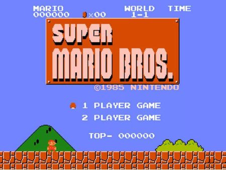
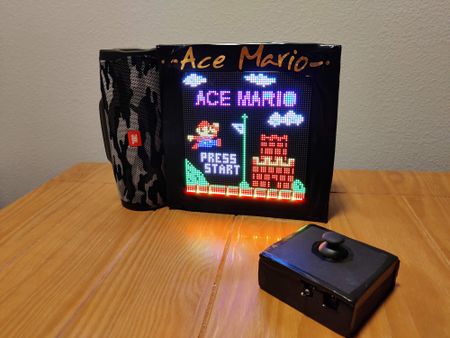
Super Mario is one of the best-selling games of all time, with more than 50 million copies sold worldwide. Our goal will be to produce a similar version 'Ace Mario' of it where the player controls Mario's movements. Mario has to race through hardships in form of obstacles and reach the mushroom kingdom which signifies victory.
Objectives & Introduction
The main objective of this project was to create a Mario video game displayed on an RGB LED matrix. We used two SJ2 boards. One for graphics processing and, the other SJ2 board was used as a gamepad controller, which controller the graphics board and sends data to the LED matrix board. Other objectives are as follows:
- Use the FreeRTOS Real-Time operating system on both the SJ2 boards.
- Interface the 64*64 RGB LED Matrix and MP3 decoder on one of the SJ2 boards.
- Interface Joystick, vibration sensor, Bluetooth on the other SJ2 board.
- Establish wireless communication between these two nodes using Bluetooth.
- Create and display characters on the LED matrix.
- Create different sound effects at different functions of the game.
- Create multiple display screens at different stages of the game.
- Integrate all the modules and develop smooth game logic.
How to Play ACE MARIO
The goal of the game is to descend forward in the right direction avoiding obstacles in the form of potholes and piranha plants and reach the Mushroom Kingdom which signifies the victory of the game.
- Using the joystick on the gamepad controller, we can control the movements of our Mario.
- a)To start the game press the joystick at the top.
- b)Mario can jump when the joystick is pressed in the upward direction and accordingly can ascend forward when pressed towards your right direction.
- As Mario ascends in the screen, the next background screen keeps appearing and we have to traverse until the game ends or we reach the mushroom kingdom.
- Avoid all the obstacles while ascending, by jumping over them.
- The entire game is time-based and lives-based i.e you need to reach the mushroom kingdom within the time span and you will be given 3 lives(heart-shaped).
- Last few seconds on your time span will be indicated by red battery lines, otherwise it will be green in color and is continuously diminishing the green lines as the game ascend.
- Failure to avoid obstacles as indicated by the game restart screen reduces your lives one by one. Hence, you will have only 3 chances to stay in the game with the usage of lives. Consequently, once you land on any obstacles and you have no lives left, the game ends.
- Having understood above, it's time to unleash the Ace Mario game now. Good Luck!
Team Members & Responsibilities
| Name | Roles / Responsibilities |
|---|---|
| |
| |
| Daya Modekar |
|
Schedule
| Week# | Start Date | End Date | Task | Status |
|---|---|---|---|---|
| 1 |
|
|
|
|
| 2 |
|
|
|
|
| 3 |
|
|
|
|
| 4 |
|
|
|
|
| 5 |
|
|
|
|
| 6 |
|
|
|
|
| 7 |
|
|
|
|
| 8 |
|
|
|
|
| 9 |
|
|
|
|
Parts List & Cost
General Parts
| Item # | Part | Vendor | Qty | Cost |
|---|---|---|---|---|
| 1 | 64x64 RGB LED Matrix | Adafruit | 1 | $54.95 |
| 2 | SJ-2 Boards | SJSU | 2 | $100.00 |
| 3 | HC-05 Bluetooth Boards | Amazon | 2 | $20.00 |
| 4 | MP3 Decoder/Player Board | Amazon | 1 | $6.99 |
| 5 | Joystick | Amazon | 1 | $4.89 |
| 6 | Power Supply for LED Matrix (5V 5A) | Amazon | 1 | $15.99 |
| 7 | JBL Speakers | already had | 1 | $0 |
| 8 | Audio Jack Cable | already had | 1 | $0 |
| 9 | MicroSD Card & Adapter | already had | 1 | $0 |
| 10 | Vibration Sensor | Amazon | 1 | $10.99 |
Design & Implementation
Hardware Integration Design
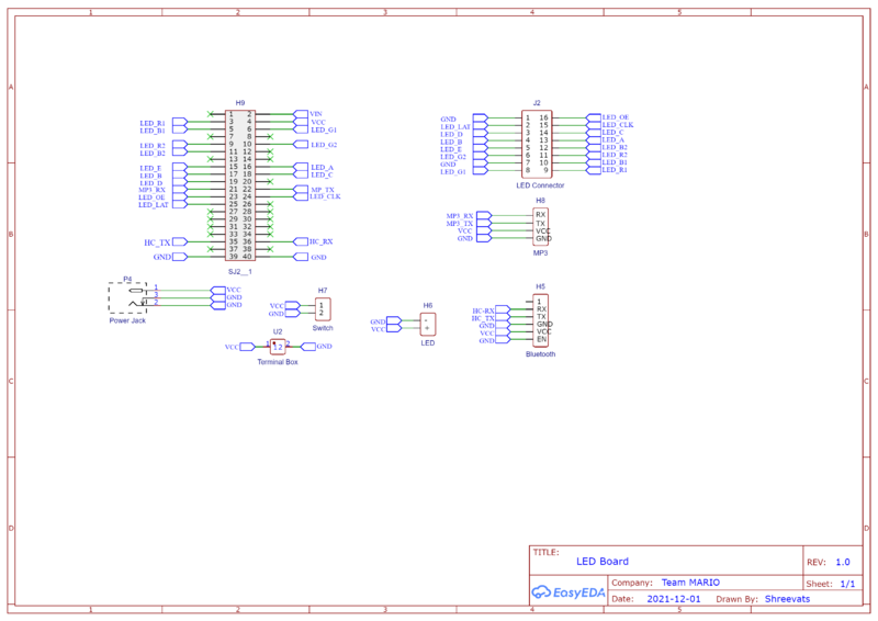
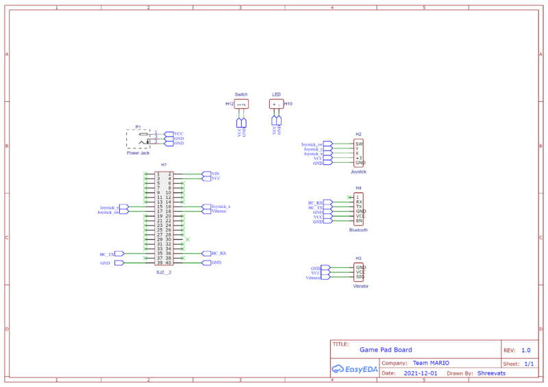
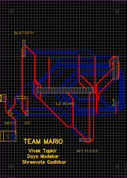
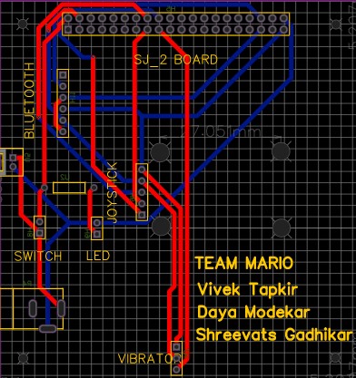
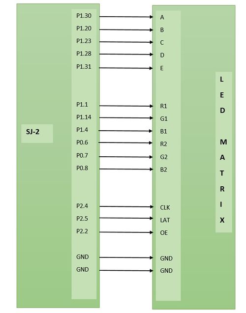
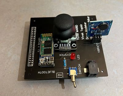
For our project, we choose EasyEDA online software for designing the PCB. EasyEDA is completely free to use and all the footprints are easily available online. Also, EasyEDA has a feature of auto-routing which is very useful. The most important thing about EasyEDA is its ability to create a PCB from schematics.
We checked our schematics several times. We also manually checked the footprints for each part before ordering the PCB. We were succeeded in 1st attempt.
Fabrication
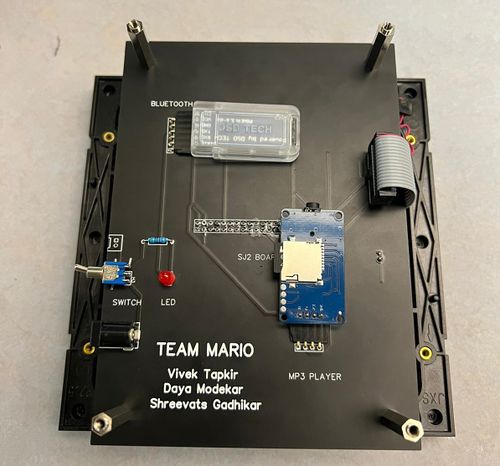
Using the EasyEDA we designed a 2 layer PCB. PCB was sent to fabrication to JLCPCB China which provided PCB within 7 days with MOQ of 5. The dimension of the 1st PCB was 8.5cm * 8 cm while the other was with the dimension of 16cm * 11.5cm. All the components were mounted as close to each other as possible to minimize the PCB dimensions.
PCB Properties:
Size: 8.5cm * 11.5cm and 16cm * 11.5cm
Signal Layers: 2
Componenets: 16
Routing width: 0.254mm
Track Width: 1mm
Clearance: 0.3mm
Via diameter: 0.61mm
Via Drill Diameter: 0.31mm
Vias: 20
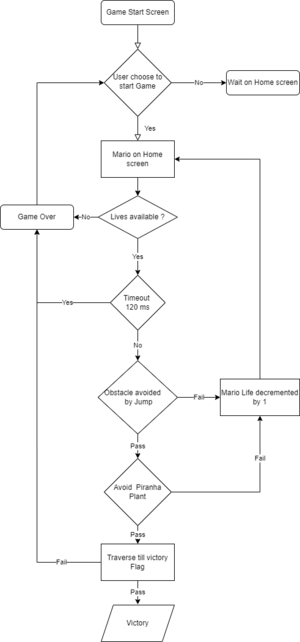
Game work Flow Diagram :
Game logic gets triggered whenever a user selects the switch button on Joystick. The whole game flow is bounded by two essential conditions which are available time span and Lives. The user is supposed to finish the victory path by avoiding all the hurdles in his path.
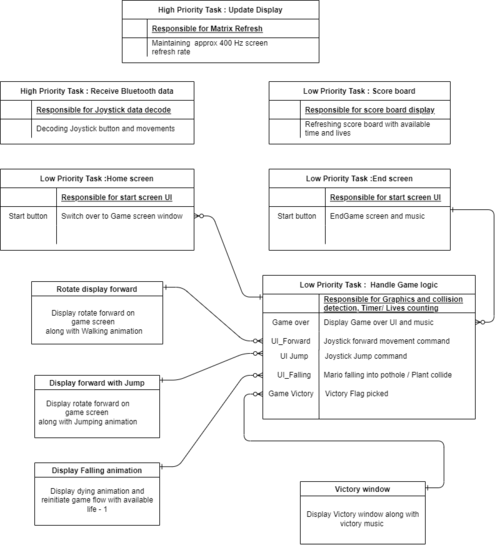
Game Task boundry diagram :
Task creation and managing tasks bandwidth was a crucial part of this project. Update display is the core heart of display driver which does refreshing of LED screen matrix at a refresh rate of around 400 Hz. Other tasks are of low priority which deals with various functionalities such as managing screen rotation, receiving Bluetooth data.
Algorithm:
MARIO_Game_state: Initially START_GAME
Display Start screen
Action: Joystick Button pressed
Switch over to Game UI
MARIO_Game_state : GAME_START_INITIATED
Game Logic Task
Available lives = 3
Time starting from 0 counting towards 150 seconds
Mario on stationery position
Switch over to the Game background screen
Start counting time within this routine till 150 seconds
if timer reached or Available lives ==0
: MARIO_Game_state -> GAME_OVER
Switch over to Game over Screen UI
If (MARIO_Game_state == GAME_START_INITIATED
&& Task tick count < 150 seconds
&& mario_available_lives !=0)
{
Action: Joystick forward command received
Rotate horizontal graphics matrix by x pixels
along with walking animation
Action: Joystick Jump command received
Rotate horizontal graphics matrix by 2x pixels
along with walking animation and music
Collision detection
If Mario position lies within Pothole
|| If Mario position collides with the Piranha plant
Mario dying animation and music
Available lives decremented by 1
Start game from the beginning
If traversal pixel coordinate reaches victory coordinate
MARIO_Game_state = MARIO_VICTORY
Switch over to Victory Screen UI and victory music
}
MP3 Decoder
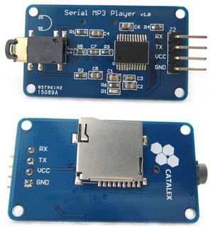
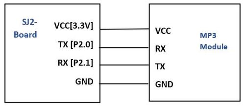
The MP3 player device which is based on a high-quality MP3 audio chip -YX5300 is used in our project to play different soundtracks based on the current state of the game such as jump, victory, game over and Mario run states. Our master controller unit (sjtwo-c board) controls MP3 playback state by sending commands to serial MP3 via UART port
Hardware Design
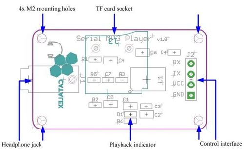
The MCU controls the device playback by sending serial commands through a TTL level UART control interface (GND, VCC, TX, RX). Sound is output through a headphone jack to headphones or an external amplifier. The board has a playback indicator led that blinks during playback and is steady otherwise. The TF card socket on the PCB reverse is for plugging in the micro SD card with mp3/wav files. The micro SD card should be formatted as fat16 or fat32 and songs must be prefixed with a unique 3 digit index number (for example, 001xxx.mp3, 002xxx.mp3, 003xxx.mp3, etc, where xxx is an arbitrary optional name). The baud rate required for communication is 9600 bps. This decoder also contains an audio jack to connect headphones or speakers.
Software Design
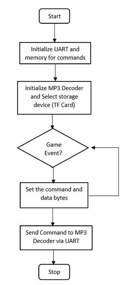
The SJ2 board initializes UART for communicating to the MP3 decoder and allocates memory to load packet information before sending via TX line.Different song tracks were played depending on the game state for example victory song when the players wins, super Mario theme song else where.
In the project, we wait for an event, such as entering the title screen or game to start playing music.
Below, are snippets of the code used to set up the commands and send them through UART. Before sending any other command, we must command the decoder to select device 2 (as described in the datasheet). A command we used in our ace Mario project was to play the song at index. The function that sends this command is called mp3_decoder__play_song_at_index(). Within commands, there are two function calls for setting up the packet (set_command_and_data()) and the other for sending the packet over UART (send_command_via_uart()) as shown below
static void intialize_command_message(mp3_decoder__msg_t *mp3_decoder_message) {
  mp3_decoder_message->mp3_decoder_command_byte.start_byte = cmd_start;
  mp3_decoder_message->mp3_decoder_command_byte.version_byte = version;
  mp3_decoder_message->mp3_decoder_command_byte.data_length = cmd_length;
  mp3_decoder_message->mp3_decoder_command_byte.feedback_byte = no_feedback;
  mp3_decoder_message->mp3_decoder_command_byte.end_byte = cmd_end;
}

static void set_command_and_data(uint8_t command, uint8_t data_0, uint8_t data_1) {
  mp3_command_message.mp3_decoder_command_byte.command_byte = command;
  mp3_command_message.mp3_decoder_command_byte.data_byte0 = data_0;
  mp3_command_message.mp3_decoder_command_byte.data_byte1 = data_1;
}


static void send_command_via_uart(void) {
  uint8_t i = 0;
  while (i < 8) {
    if (uart__polled_put(uart, mp3_command_message.mp3_decoder_command.bytes[i])) {
      i++;
    }
  }
}

static void select_storage_device(void) {
  static const uint8_t device = 0x02;
  set_command_and_data(mp3_decoder__select_device, no_data, device);
  send_command_via_uart();
}

void mp3_decoder__play_song_at_index(uint8_t index) {
  set_command_and_data(mp3_decoder__play_at_index, no_data, index);
  send_command_via_uart();
}
Bluetooth Interface
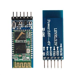
For this project, we used two HC-05 Bluetooth modules. One Bluetooth was configured on the LED matrix controller board while the other was configured on the gamepad controller. The Bluetooth configured on the led matrix controller worked as a slave, only receives commands, while the one configured on the gamepad worked as master, sending controls to the other controller. The master Bluetooth connected to the gamepad controller transmitted the joystick direction. The transmitted direction was in the form of x and y coordinates. The UP and FORWARD direction was calibrated using the x and y coordinates. So along with UP and FORWARD direction, the joystick switch button data was also transmitted using Bluetooth.
We selected the HC-05 Bluetooth module to transmit data over other modules because of their ease to configure, they are extremely reliable and also easy to set up. Both the Bluetooth modules were configured using AT commands. Using AT commands made our job easy to set one Bluetooth as a master while the other as a slave. The best thing about using AT commands is that we can change the configuration as per our needs. The UART baud rate was set to 38400.
Hardware Design
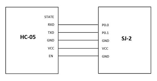
The HC-05 Bluetooth module was connected to both boards using the SJ2 pins. The pins used were P0.0 and P0.1. These Bluetooth modules communicate with each other over the UART interface. The gamepad controller board process the joystick signals to UP and FORWARD and also the button press and then sends them to the Bluetooth module via UART.
Software Design
The following function "receive_from_bluetooth" was used to receive data from the Bluetooth.
void receive_from_bluetooth (void *p) {
 char bluetooth_command_received[50];
 bluetooth_command_received[0] = '\0';
 while (1) {
   char received_data = '\0';
   if (uart__get(UART__3, &received_data, portMAX_DELAY)) {
     strncat(bluetooth_command_received, &received_data, 1);
     if (received_data == '\n') {
       bluetooth__process_receive_data(bluetooth_command_received);
       strcpy(bluetooth_command_received, "\0");
    }
   }
  }
 }
The following code snippet was used to process the received data. It simply compares the strings and, if the match is found the direction is set accordingly.
void bluetooth__process_receive_data(char string[]) {
 if (strcmp(string, "CENTERED\r\n") == 0){
   set_joystick_direction(CENTERED);
   printf("CENTERED\n");
 } else if (strcmp(string, "RIGHT\r\n") == 0){
   set_joystick_direction(RIGHT);
   printf("RIGHT\n");
 } else if (strcmp(string, "JOYSTICK_ON\r\n") == 0) {
   set_joystick_button_pressed(true);
   printf("JOYSTICK_BUTTON\n");
 }
}
Game pad Controller
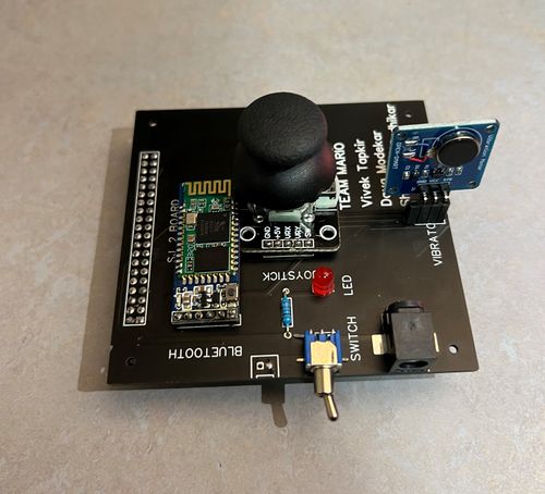
Gamepad Controller basically consists of only three main components. Firstly the joystick, which is used to get the UP and FORWARD direction, and also the press button. Second is the Bluetooth module which is used to transmit the data via UART to the other board. And lastly, the vibration sensor to produce the vibration. The vibration sensor is used to get the real game feel.
Joystick
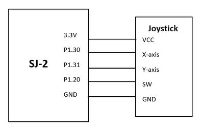
The joystick was interfaced on the Game-pad controller. We used a joystick to get a UP and FORWARD direction. The joystick was configured using ADC pins of the SJ2 board. The Joystick provides an analog output, therefore they were connected to ADC pins to get the digital values. The values of the X-axis and Y-axis varied from 0 to 4095. The center was 2048 for both X-axis and Y-axis. The UP and FORWARD direction was calculated using these ADC values. The joystick also had a digital switch. This digit switch was used as a press button in our game. These three contents (i.e UP, FORWARD, Button_press) were transmitted to the led board using Bluetooth.
Hardware Design
The hardware design was pretty simple. The two analog output pins i.e X-axis and Y-axis were connected to ADC pins of the SJ2 board. The ADC pins used were P1.30 and P1.31 to get the UP direction and the FORWARD direction. The digital switch was connected to one of the gpio pins on the SJ2 board. This gpio pin was read to detect if the switch was pressed.
Software Design
This code snippet below demonstrates how we calculated the direction using the joystick. The joystick provides the analog values, so we used the ADC pins of the SJ2 board to get the digital values. The values range from 0 to 4095. According to these values threshold for UP and FORWARD/RIGHT were set.
static const int16_t UP_threshold = 500;
static const int16_t RIGHT_threshold = 3500;
joystick_direction_t joystick_controls__get_joystick_direction(void) {
 joystick_direction_t joysticks_direction = CENTERED;
 int joystick_pos_x = adc__get_channel_reading_with_burst_mode(X_axis);
 int joystick_pos_y = adc__get_channel_reading_with_burst_mode(Y_axis);
 if (joystick_pos_y < UP_threshold) {
   joysticks_direction = UP;
   printf("UP\n");
 }
 if (joystick_pos_x > RIGHT_threshold) {
   joysticks_direction = RIGHT;
   printf("RIGHT\n");
 }
 vTaskDelay(500);
 return joysticks_direction;
}
Vibration Module
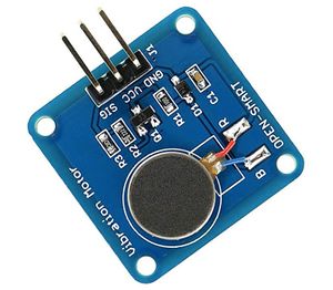
A vibration module was used to produce the vibration on the game-pad controller to get the real feel of the game. The vibration module was triggered on the Mario jump state and also when Mario died.
Hardware Design
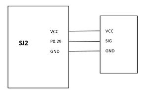
Vibration module consists of just 3 pins. VCC for power, Signal pin to trigger the pin, and GND. The signal pin of the vibration module was connected to one of the gpio pin (P0.29) of the SJ2 board.
Software Design
A GPIO pin was used to signal the SIG pin of the vibration module.
gpio_s vibration_module_pin = {1, 29};

gpio__set(vibration_module_pin);
 delay__ms(500);
 gpio__reset(vibration_module_pin);
Game Graphics Implementation
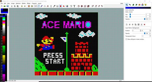
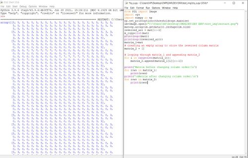
The mtPaint software(open source) is a fantastic resource for planning out levels, background, and designing characters of the game . Images drawn using mtPaint can be converted into 2d-array representation using a python script or other image processing software. This is going to be much easier than writing entire screens out by hand and also saves time.
Project Learnings
- Creating various Mario and Background images using MT-paint and Python scripts helped us in achieving better Graphics precision.
- Creating immersive Background graphics when Mario is traversing through the green bushes .
- Establishing board to board communication via Bluetooth module and optimizing the response time between the Matrix controller and joystick.
- Concepts of FreeRTOS , Communication using UART and basic learning helped us .
Testing & Technical Challenges
Graphics development
- Creating a motion effect for Mario traversal was a big challenge and the visual effect of Jump and Walk
Another trouble was running collision detection when Mario is not moving from his fixed position
- Came up with a solution of having whole display UI as a single matrix and traversing it as per Jump or forward movement.
Same position Jump and screen traversal should happen at the same time.
MP3 Decoder
- The datasheet lacks some information and clarity on module initialization and working. Initially, non of the commands appeared to work or have any effect. The issue was resolved after sending the command to select a device, which was not explicitly stated in the datasheet. Once this command is first sent, the MP3 decoder now begins accepting commands.
- The TF card folder structure for songs was unclear in the first go.
Conclusion
Indeed, it was a great learning experience. It sharpened our driver writing skills as we coded each module we used (LED matrix, MP3 decoder, Bluetooth, etc.).We were able to learn a lot about a real-world projects such as FreeRTOS applications, drivers, PCB design, power management circuits, git source code management, and final integration testing. This project allowed us to understand the importance of writing down requirements, planning a schedule for development, and teamwork. Throughout the entire duration of this project, we encountered numerous challenges such as difficulty getting the LED matrix driver up and running, figuring out how to implement collision detection with so many game objects, hardware integration, and writing and maintaining our complex game logic state machine and much more. Despite the challenges and setbacks we faced, we were able to overcome every single one of them in order to build a finished product that we are all proud of.
Project Video
Project Source Code
Acknowledgement
We'd want to express our gratitude to our professor Preet and all of the ISAs for putting together such a fantastic class and for setting such high standards. This instilled in us the desire to go above and beyond.
References Used
LED Matrix
Image Designing
MP3 Decoder
HC-05 Bluetooth Modules
PCB Designing
