Difference between revisions of "F21: Flame Over"
Proj user4 (talk | contribs) (→Design & Implementation) |
Proj user4 (talk | contribs) (→References Used) |
||
| (53 intermediate revisions by the same user not shown) | |||
| Line 1: | Line 1: | ||
== Abstract == | == Abstract == | ||
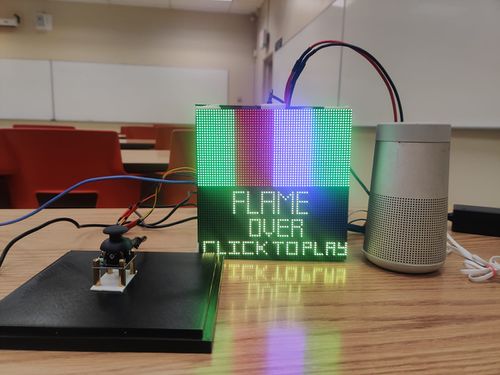
| − | Flame Over is a single-player mode game where the player moves a fire fighter to destroy the fire flames that come shooting at the player using a water gun. The player is granted four lives at the start of the game at each level. The Player’s lives will decrease by one for every three flames that touch the fire fighter. The player transits to the next level when enough flames are destroyed at each level. The speed of the flames approaching the fire fighter varies between levels. | + | Flame Over is a single-player mode game where the player moves a fire fighter to destroy the fire flames that come shooting at the player using a water gun. The player is granted four lives at the start of the game at each level. The Player’s lives will decrease by one for every three flames that touch the fire fighter. The player transits to the next level when enough flames are destroyed at each level. The speed of the flames approaching the fire fighter varies between levels. If the fireman loses all the lives, player loses. If enough flames are destroyed at the end of level 3, player wins. |
== Objectives & Introduction == | == Objectives & Introduction == | ||
[[File:Flame over Cover.jpeg|thumb|500x500px|Game Console|right]] | [[File:Flame over Cover.jpeg|thumb|500x500px|Game Console|right]] | ||
| − | |||
=== Objectives === | === Objectives === | ||
| Line 27: | Line 26: | ||
** Built game characters on LED matrix display | ** Built game characters on LED matrix display | ||
** PCB Schematic and Board Design | ** PCB Schematic and Board Design | ||
| + | ** Component Integration on PCB | ||
** Hardware wiring and assembly | ** Hardware wiring and assembly | ||
** 3D case design and packaging | ** 3D case design and packaging | ||
* Vaidehi Deshpande | * Vaidehi Deshpande | ||
** Joystick Interfacing - ADC driver | ** Joystick Interfacing - ADC driver | ||
| − | ** | + | ** MP3 Serial Player Driver |
** Zigbee interfacing with UART driver for transmission and reception | ** Zigbee interfacing with UART driver for transmission and reception | ||
** Built game characters on LED matrix display | ** Built game characters on LED matrix display | ||
| + | ** Component Integration on PCB | ||
** Hardware wiring and assembly | ** Hardware wiring and assembly | ||
| Line 289: | Line 290: | ||
== Design & Implementation == | == Design & Implementation == | ||
| − | |||
==== '''Pin Configuration''' ==== | ==== '''Pin Configuration''' ==== | ||
| Line 377: | Line 377: | ||
! scope="row"| RX | ! scope="row"| RX | ||
| UART Receive From Game Controller | | UART Receive From Game Controller | ||
| − | ! | + | ! P2_8 |
|- | |- | ||
! scope="row"| VCC | ! scope="row"| VCC | ||
| Line 401: | Line 401: | ||
! scope="row"| TX | ! scope="row"| TX | ||
| UART Transmit to Main Board | | UART Transmit to Main Board | ||
| − | ! | + | ! P2_9 |
|- | |- | ||
! scope="row"| VCC | ! scope="row"| VCC | ||
| Line 427: | Line 427: | ||
! scope="row"| Vy | ! scope="row"| Vy | ||
| Y-axis ADC Reading for character movement | | Y-axis ADC Reading for character movement | ||
| − | ! | + | ! P1_30 |
|- | |- | ||
| Line 433: | Line 433: | ||
</li> | </li> | ||
</ul></div> | </ul></div> | ||
| + | === '''Printed Circuit Board'''=== | ||
| + | ==== Layout & Design ==== | ||
| + | |||
| + | We have designed our Printed Circuit Board using 'AUTODESK EAGLE software', version 9.6.2.The lecture on Eagle PCB provided by Professor Preet provided a good insight about using this software and building a PCB. As suggested during the lecture, we followed Sparkfun Eagle tutorials and libraries while working on the PCB. These resources served as a good source of information for us and made our work easy. | ||
| + | |||
| + | For PCB fabrication, we selected the PCB manufacturer 'JLCPCB' because their production lead-time was less compared to other manufacturers. They had an efficient customer service and faster delivery option that helped us to get our PCBs on time. | ||
| + | |||
| + | '''Schematic and Board Design of PCB''' | ||
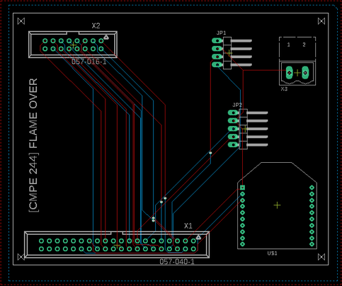
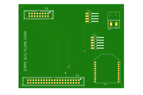
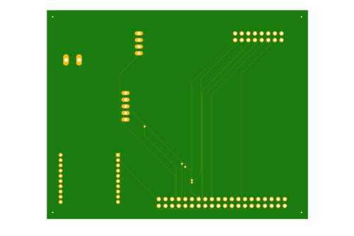
| + | '''1.''' We created a common PCB design for both of our SJ2 Boards. | ||
| + | '''2.''' The following connectors were used to design a schematic for our design | ||
| + | •LED Matrix - 10-pin series 057 contact pc board low profile headers | ||
| + | •SJ2 Board - 40-pin series 057 contact pc board low profile headers | ||
| + | •Joystick - 5 pin header | ||
| + | •MP3 Serial Player - 4 pin header | ||
| + | •Xbee - Adafruit library Xbee Module | ||
| + | |||
| + | |||
| + | [[File:Board Layout Flame Over.png|thumb|500x600px|PCB Board Layout|center]] | ||
| + | <center> | ||
| + | <table> | ||
| + | <tr> | ||
| + | <td> | ||
| + | [[File:PCB Board Layout Top Layer.png|thumb|500x600px|PCB Layout - Top Layer|left]] | ||
| + | </td> | ||
| + | <td> | ||
| + | </td> | ||
| + | <td> | ||
| + | [[File:PCB Board Layout Bottom Layer.png|thumb|500x600px|PCB Layout - Bottom Layer|left]] | ||
| + | </td> | ||
| + | </tr> | ||
| + | </table> | ||
| + | </center> | ||
| + | |||
| + | === Hardware Interface === | ||
| + | [[File:FlameOver_Block_Diagram.jpg|thumb|500px|Block Diagram|centre]] | ||
| + | |||
| + | We used two SJ2 boards for this project. One main SJ2 board to drive the LED Matrix Display and the MP3 Decoder, another SJ2 board to collect the control signals from the Analog Joystick connected to it. These signals are wirelessly transmitted from this board to the main SJ2 board driving the LED Display. This communication is achieved using Zigbee over UART. | ||
| + | |||
| + | Universal Asynchronous Receiver Transmitter (UART) is also used as an interface to connect the main SJ2 board and MP3 Serial Player. UART_3 is configured for YX5300 MP3 player. Below is the pinout connections between UART and MP3 Serial Player: | ||
| + | |||
| + | === Hardware Implementation === | ||
==== LED Matrix ==== | ==== LED Matrix ==== | ||
A 64x64 RGB LED Matrix Panel is used as the display for this game. It has 64 rows and 64 columns. It is divided into two 32x64 sections. Each LED pixel can be accessed and controlled individually. A decoder is used to access individual row. One row can be selected at a time using A,B,C,D and E pins. This enables us to select one row in each of the 32X64 sections. Columns are controlled using shift registers, every bit in the shift register controls the corresponding column. On every falling edge of the clock pulse, the values at R1, B1, G1, R2, B2, and G2 pins are stored into the shift register and the register shifts the data by one bit. After this, the data on the shift register is passed onto the individual LED's when both OE and LE pins are set to high. | A 64x64 RGB LED Matrix Panel is used as the display for this game. It has 64 rows and 64 columns. It is divided into two 32x64 sections. Each LED pixel can be accessed and controlled individually. A decoder is used to access individual row. One row can be selected at a time using A,B,C,D and E pins. This enables us to select one row in each of the 32X64 sections. Columns are controlled using shift registers, every bit in the shift register controls the corresponding column. On every falling edge of the clock pulse, the values at R1, B1, G1, R2, B2, and G2 pins are stored into the shift register and the register shifts the data by one bit. After this, the data on the shift register is passed onto the individual LED's when both OE and LE pins are set to high. | ||
| Line 466: | Line 507: | ||
MP3 Serial Player module is a simple MP3 player device which is based on a high quality MP3 audio chip. It can support 8kHz - 48kHz sampling frequency MP3 and WAV file formats. Also, this board has a TF card socket so that a SD card can be inserted that stores audio files. SJTwo board can control this module via UART port, such as switch songs, change the volume and play mode, and so on. | MP3 Serial Player module is a simple MP3 player device which is based on a high quality MP3 audio chip. It can support 8kHz - 48kHz sampling frequency MP3 and WAV file formats. Also, this board has a TF card socket so that a SD card can be inserted that stores audio files. SJTwo board can control this module via UART port, such as switch songs, change the volume and play mode, and so on. | ||
| − | The SD card should be formatted as FAT16 or FAT32 and should have some audio files with .mp3 or .wav formats. If user wants to create separate folders then those should be created as “01”, “02” and the songs should be with the names 001xxx.mp3/ 002xxx.mp3/ 003xxx.mp3 in those created folders. | + | The SD card should be formatted as FAT16 or FAT32 and should have some audio files with .mp3 or .wav formats. If the user wants to create separate folders then those should be created as “01”, “02” and the songs should be with the names 001xxx.mp3/ 002xxx.mp3/ 003xxx.mp3 in those created folders. |
| + | |||
| + | [[File:Flame_over_MP3.png|thumb|500px|MP3 and SJTwo Board interface|centre]] | ||
| + | |||
| + | ====='''Software Implementation:'''===== | ||
| + | The module communicates with the microcontroller through commands which are a combination of data and cmd fields. The cmd field allows us to control the module. Commands are available for the functions like Play NEXT_SONG, PREV_SONG, PLAY_WITH_INDEX, etc. The data field is required, the data field is required; this is noted, otherwise it is set to zero and ignored., otherwise it is set to zero and ignored. | ||
| + | |||
| + | |||
| + | |||
| + | Below is the command list followed for this project: | ||
| + | |||
| + | *Next_song 0x01 Play next song. | ||
| + | *Prev_song 0x02 Play previous song. | ||
| + | *Play_with_index 0x03 Play song with index number. Data is the index of the file. | ||
| + | *Volume_up 0x04 Volume increase by one. | ||
| + | *Volume_down 0x05 Volume decrease by one. | ||
| + | *Set_volume 0x06 Set the volume to level specified. Data is the volume level [0..30]. | ||
| + | *Set_equalizer 0x07 Set the equalizer to specified level. Data is [0..5] – 0=normal, 1=pop, 2=rock, 3=jazz, 4=classic or 5=base. | ||
| + | *Sng_cycl_play 0x08 Loop play (repeat) specified track. Data is the track number. | ||
| + | *Sel_dev 0x09 Select file storage device. The only valid choice for data is tf (0x02). | ||
| + | *Sleep_mode 0x0a Chip enters sleep mode. | ||
| + | *Wake_up 0x0b Chip wakes up from sleep mode. | ||
| + | *Reset 0x0c Chip reset. | ||
| + | *Play 0x0d Playback restart. | ||
| + | *Pause 0x0e Pause playback. | ||
| + | *Play_folder_file 0x0f Play the file with the specified folder and index number | ||
| + | *Stop_play 0x16 Stop playback. | ||
| + | *Folder_cycle 0x17 Loop playback within specified folder. Data is the folder index. | ||
| + | *Shuffle_play 0x18 Playback shuffle mode. Data is 0 to enable, 1 to disable. | ||
| + | *Set_sngl_cycl 0x19 Set loop play (repeat) on/off for current file. Data is 0 to enable, 1 to disable. | ||
| + | *Set_dac 0x1a Dac on/off control (mute sound). Data is 0 to enable dac, 1 to disable dac (mute). | ||
| + | *Play_w_vol 0x22 Play track at the specified volume. Data hi byte is the track index, low byte is the volume level [0..30]. | ||
| + | *Shuffle_folder 0x28 Playback shuffle mode for folder specified. Data high byte is the folder index. | ||
| + | |||
| + | |||
| + | '''Code Snippet of MP3 module:''' | ||
| + | |||
| + | void MP3__command(uint8_t command, uint16_t dat) { | ||
| + | MP3_buffer[0] = 0x7e; // starting byte | ||
| + | MP3_buffer[1] = 0xff; // version | ||
| + | MP3_buffer[2] = 0x06; // the number of bytes of the command without starting byte and ending byte | ||
| + | MP3_buffer[3] = command; // | ||
| + | MP3_buffer[4] = 0x00; // 0x00 = no feedback, 0x01 = feedback | ||
| + | MP3_buffer[5] = (uint8_t)(dat >> 8); // datah | ||
| + | MP3_buffer[6] = (uint8_t)(dat); // datal | ||
| + | MP3_buffer[7] = 0xef; // ending byte | ||
| + | for (uint8_t i = 0; i < 8; i++) | ||
| + | uart__polled_put(UART__3, MP3_buffer[i]); | ||
| + | } | ||
| + | |||
| + | ==== '''Joystick:''' ==== | ||
| + | The joystick is similar to two potentiometers connected together , one for the vertical movement (Y-axis), other for horizontal movement (X-axis). The 4 direction output values from the joystick are used to move the fireman positions right, left, up and down. The ADC clock frequency was set to 12MHz. | ||
| + | |||
| + | '''Features:''' | ||
| + | |||
| + | *Two independent Potentiometer: one for each axis ( X and Y) | ||
| + | *Auto return to center position | ||
| + | *Low weight | ||
| + | *Cup-type Knob | ||
| + | *Compatible to interface with Arduino or with most microcontrollers | ||
| + | |||
| + | '''Technical Specifications:''' | ||
| + | |||
| + | *Operating Voltage: 5V | ||
| + | *Internal Potentiometer value: 10k | ||
| + | *2.54mm pin interface leads | ||
| + | *Dimensions: 1.57 in x 1.02 in x 1.26 in (4.0 cm x 2.6 cm x 3.2 cm) | ||
| + | *Operating temperature: 0 to 70 °C | ||
| + | |||
| + | |||
| + | [[File:Flame_over_joystick.png|thumb|500px|Joystick|centre]] | ||
| + | |||
| + | ====='''Software Implementation:'''===== | ||
| + | |||
| + | The joystick communicates with the SJTwo board via ADC pins. Joystick provides two outputs which are X-axis (connected to ADC_2: P0_25 of SJTwo), Y-axis (connected to ADC_4: P1_30 of SJTwo). The outputs at X-axis and Y-axis are taken as inputs for changing the fireman positions. The switch takes the input from the user and is used to fire the water bullets towards the generated fire flames. | ||
| + | |||
| + | '''ADC Initialization:''' | ||
| + | |||
| + | gpio__construct_with_function(GPIO__PORT_0, 25, GPIO__FUNCTION_1); // ADC2 | ||
| + | gpio__construct_as_output(GPIO__PORT_0, 25); | ||
| + | LPC_IOCON->P0_25 &= ~((1 << 3) | (1 << 4)); | ||
| + | gpio__construct_with_function(GPIO__PORT_1, 30, GPIO__FUNCTION_3); // ADC4 | ||
| + | gpio__construct_as_output(GPIO__PORT_1, 30); | ||
| + | LPC_IOCON->P1_30 &= ~((1 << 3) | (1 << 4)); | ||
| + | |||
| + | |||
| + | '''Threshold range for different joystick movements:''' | ||
| + | |||
| + | if (water_splash_flag == true) { | ||
| + | control_signal = water_splash; | ||
| + | water_splash_flag = false; | ||
| + | } else if (((ValueRx > 1900) && (ValueRx < 3000)) && ((ValueRy > 1900) && (ValueRy < 3000))) { | ||
| + | control_signal = center; | ||
| + | } else if ((((ValueRx > 1900) && (ValueRx < 3000)) && (ValueRy < 100))) { | ||
| + | control_signal = left; | ||
| + | } else if (((ValueRx > 3000) && (ValueRx < 4096)) && ((ValueRy > 15) && (ValueRy < 200))) { | ||
| + | control_signal = left_up_diagonal; | ||
| + | } else if (((ValueRx > 15) && (ValueRx < 200)) && ((ValueRy > 15) && (ValueRy < 200))) { | ||
| + | control_signal = left_down_diagonal; | ||
| + | } else if ((ValueRx < 50) && ((ValueRy > 1900) && (ValueRy < 3000))) { | ||
| + | control_signal = down; | ||
| + | } else if ((((ValueRx > 1900) && (ValueRx < 3000)) && ((ValueRy > 3000) && (ValueRy < 4096)))) { | ||
| + | control_signal = right; | ||
| + | } else if (((ValueRx > 15) && (ValueRx < 100)) && ((ValueRy > 3000) && (ValueRy < 4096))) { | ||
| + | control_signal = right_down_diagonal; | ||
| + | } else if ((ValueRx > 3000) && ((ValueRx < 4096)) && (ValueRy > 3000) && ((ValueRy < 4096))) { | ||
| + | control_signal = right_up_diagonal; | ||
| + | } else if (((ValueRx > 3000) && (ValueRx < 4096)) && ((ValueRy > 1900) && (ValueRy < 3000))) { | ||
| + | control_signal = up; | ||
| + | } else { | ||
| + | control_signal = center; | ||
| + | } | ||
| + | return control_signal; | ||
| + | } | ||
| + | |||
| + | ==== '''ZigBee:''' ==== | ||
| + | Zigbee is a wireless communication module which use IEEE 802.15.4 standard. 802.15.4 is a IEEE standard for low power applications of radio frequency. Zigbee generally operates in the 2.4GHz range (although there are geographic variations), and supports data ranges from 20 to 250 kbits/s.The transmission distance though, is small compared to the likes of LoRa. It is 10 to 100 m, whereas LoRa can transmit over a few kilometers. Another thing to note is that Zigbee communication doesn’t work very well if there is no line of sight between transmitter and receiver.Even minor obstacles have been observed to significantly degrade the communication. | ||
| + | Our project uses two SJTwo boards and these two boards are connected using a ZigBee module on each board. Zigbee can communicate with external devices such as sensors and communication devices. The Zigbee module needs to be configured using XCTU software. | ||
| + | |||
| + | |||
| + | [[File:FlameOver_XBeeMod.png|thumb|500px|Xbee Module|centre]] | ||
| + | |||
| + | ===== '''Interface between SJTwo board and ZigBee:''' ===== | ||
| + | |||
| − | === | + | [[File:Flame_over_xbee.png|thumb|500px|Xbee Module|centre]] |
| − | + | ||
| + | ====='''Software Implementation'''===== | ||
| + | '''Transmitter end:''' | ||
| + | static void water_splash_task(void *pv) { | ||
| + | while (1) { | ||
| + | data = joystick__sendControl(); | ||
| + | // fprintf(stderr, "data=%d\n", data); | ||
| + | if (!(LPC_GPIO4->PIN & (1 << 28))) { | ||
| + | water_splash_flag = true; | ||
| + | } | ||
| + | uart_lab__polled_put(UART_2, data); // XBee TX | ||
| + | fprintf(stderr, "Sent: %i over UART to the other board\n", data); | ||
| + | vTaskDelay(50); | ||
| + | } | ||
| + | } | ||
| + | '''Receiver end:''' | ||
| − | === | + | void startup_update_display_delay(void) { |
| − | + | if (!start_flag) { | |
| + | for (int i = 0; i < 90; i++) { | ||
| + | led_matrix__updateDisplay(); | ||
| + | flameover_xbee_recvr__receive_data(); // XBee RX | ||
| + | if (joystick_control_signal == 9) { | ||
| + | start_flag = true; | ||
| + | i = 100; | ||
| + | break; | ||
| + | } | ||
| + | } | ||
| + | } | ||
| + | } | ||
| − | |||
| − | |||
=== Software Design and Implementation === | === Software Design and Implementation === | ||
| Line 514: | Line 702: | ||
**When the flame hits the fireman for 3 times, fireman's health reduced by 1. Burst animation is played at the collision. And once the fireman's health reduces to 20 from the initial 100, the player loses all lives and loses the game. | **When the flame hits the fireman for 3 times, fireman's health reduced by 1. Burst animation is played at the collision. And once the fireman's health reduces to 20 from the initial 100, the player loses all lives and loses the game. | ||
| − | |||
| − | |||
| − | |||
| − | + | === '''3D Packaging'''=== | |
| + | To accomodate the two PCB Boards and the hardware components in one single black box, we created a 3D case with a lid. We designed the 3D design using the AUTODESK TINKERCAD web application and generated the .stl files for 3D print. We did the 3D printing at SJSU library. In order to get the print in less amount of time , we had to correct the infill density and other parameters using Ultimaker Cura application. Finally, by building the 3D case and by enclosing the components inside it, we were able to simulate a good gaming experience. | ||
| − | |||
| − | |||
| − | |||
| − | |||
| − | |||
| − | |||
| − | |||
| − | |||
| − | |||
| − | |||
<center> | <center> | ||
<table> | <table> | ||
<tr> | <tr> | ||
<td> | <td> | ||
| − | [[File: | + | [[File:Case 3D View.png|thumb|500x600px|TinkerCad 3D view of the Box|left]] |
| + | </td> | ||
| + | <td> | ||
| + | </td> | ||
| + | <td> | ||
| + | [[File:LID 3D View .png|thumb|500x600px|TinkerCad 3D view of the Box Lid|right]] | ||
| + | </td> | ||
| + | </tr> | ||
| + | </table> | ||
| + | </center> | ||
| + | <center> | ||
| + | <table> | ||
| + | <tr> | ||
| + | <td> | ||
| + | [[File:3D printed Box.jpeg |thumb|500x600px|3D Box|left]] | ||
</td> | </td> | ||
<td> | <td> | ||
</td> | </td> | ||
<td> | <td> | ||
| − | [[File: | + | [[File:3D printed Box-Lid.jpeg|thumb|500x600px|3D Box Lid|left]] |
</td> | </td> | ||
</tr> | </tr> | ||
| Line 547: | Line 737: | ||
== Testing & Technical Challenges == | == Testing & Technical Challenges == | ||
| − | |||
| − | * | + | === Testing === |
| − | + | Below are the steps taken for testing and verification: | |
| − | + | * Verified that the pin connections are correct after hardware integration on PCB | |
| − | + | * Verified continuity between the pins. | |
| + | * Verified that there are no short connections after the PCB fabrication. | ||
| + | * Calibrated the Joystick for precise movements. | ||
| + | * Intensive testing performed to confirm synchronisation of soud effects with the game logic. | ||
| − | ''' | + | === Technical Challenges === |
| − | + | '''LED Matrix''' | |
| + | * Designing the main character of the game was time consuming as it required proper plotting of pixel data and proper alignment. | ||
| + | * Handling the wiring of the matrix without the PCBs proved to be a great challenge. | ||
| + | * Finding a good refresh rate was crucial for the display. The screen ended up flickering for few refresh rates. The task design had to be curated and the refresh rate had to be reevaluated to mitigate flickering. | ||
| + | * In the initial stages of familiarizing with the LED matrix display, we observed random pixels being lit instead of the desired ones. We referred to online sources to see what we were doing wrong. We later changed our initializing sequence and it started working fine. | ||
| − | ''' | + | '''MP3 Serial Player and Sound Effects -''' |
| + | * Songs are referenced by folder and by song ‘index’, although it seems that the numeric index is sometimes ignored and the songs played in the order they are stored in the SD card. The documentation is unclear on this and seems to imply both situations. So, even if you plan only one playlist, it is better to keep them in a ’01’ folder and save all the songs to the SD card at the same time. | ||
| + | * Finding the appropriate game sounds for free was tough as most of the sounds were paid. | ||
| − | + | '''PCB Designing -''' | |
| + | * Placement of components on the schematic and board layout required proper assessment in order to avoid congestion of components while soldering. | ||
| − | + | '''Exhausting UART peripherals -''' | |
| + | * We initially planned of using only one SJ2 board for the driving the LED display, MP3 Decoder and Joystick. But we exhausted the pins on the SJ2 board with LED Matrix display and MP3 Decoder. So we used another SJ2 board to wirelessly transmit the joystick signals to the main board over zigbee. | ||
== Conclusion == | == Conclusion == | ||
| − | + | This project was a great hands on learning experience on freertos and real time task synchronization. It gives a complete understanding of how to design an entire free rtos based system from scratch. While working with this project, we understood the importance of semaphores, task priorities, stack utilization. It was challenging but we thoroughly enjoyed the process. | |
=== Project Video === | === Project Video === | ||
| Line 570: | Line 770: | ||
=== Project Source Code === | === Project Source Code === | ||
| − | * [https:// | + | * [https://gitlab.com/VaidehiD_23/flame-over/-/tree/led_matrix Git Source Code Link] |
== References == | == References == | ||
=== '''Acknowledgement''' === | === '''Acknowledgement''' === | ||
| − | We would like to thank our Professor Preetpal Kang for | + | We would like to thank our Professor Preetpal Kang for all the learnings from this course. This course engages the students and gives a hands on experience of everything. We'd also like to thank our ISA team for all the suggestions and timely help with the Project. And a kudos to our entire team, Flame Over. With full support and cooperation from each other, we were successfully able to complete this project as planned. |
=== '''References Used''' === | === '''References Used''' === | ||
| + | *[http://socialledge.com/sjsu/index.php/Main_Page WikiPage by Preetpal Kang] | ||
| + | *[http://www.socialledge.com/sjsu/index.php?title=Realtime_OS_on_Embedded_Systems FreeRTOS documentations] | ||
*[https://learn.sparkfun.com/tutorials/rgb-panel-hookup-guide?_ga=2.111533508.177452041.1605078754-2035904423.1601235282 RGB Panel Hookup Guide 1] | *[https://learn.sparkfun.com/tutorials/rgb-panel-hookup-guide?_ga=2.111533508.177452041.1605078754-2035904423.1601235282 RGB Panel Hookup Guide 1] | ||
| − | *[ | + | *[https://www.prf.jcu.cz/generator-led-matrix/index.htm/ LED Matrix Code Generator] |
| + | *[https://learn.sparkfun.com/tutorials/using-eagle-schematic/all Sparfun Tutorial for PCB Design] | ||
*[https://www.youtube.com/watch?v=1AXwjZoyNno AutoDesk Eagle Software Tutorial] | *[https://www.youtube.com/watch?v=1AXwjZoyNno AutoDesk Eagle Software Tutorial] | ||
| − | |||
*[https://arduinoplusplus.wordpress.com/2018/07/23/yx5300-serial-mp3-player-catalex-module/ MP3 commands] | *[https://arduinoplusplus.wordpress.com/2018/07/23/yx5300-serial-mp3-player-catalex-module/ MP3 commands] | ||
| + | *[https://www.youtube.com/watch?v=yK__DhapraA TinkerCad Tutorial] | ||
Latest revision as of 07:59, 18 December 2021
Contents
- 1 Abstract
- 2 Objectives & Introduction
- 3 Schedule
- 4 Parts List & Cost
- 5 Design & Implementation
- 6 Testing & Technical Challenges
- 7 Conclusion
- 8 References
Abstract
Flame Over is a single-player mode game where the player moves a fire fighter to destroy the fire flames that come shooting at the player using a water gun. The player is granted four lives at the start of the game at each level. The Player’s lives will decrease by one for every three flames that touch the fire fighter. The player transits to the next level when enough flames are destroyed at each level. The speed of the flames approaching the fire fighter varies between levels. If the fireman loses all the lives, player loses. If enough flames are destroyed at the end of level 3, player wins.
Objectives & Introduction
Objectives
- Write driver module to display game characters and update the display continuously at an optimum refresh rate
- Implement game algorithm for movement of player and flames in real-time, generate water splash bullets.
- Implement player lives count, player health and collision algorithms.
- Write driver module to receive directions from the input device (joystick) via zigbee.
- Fetch Joystick data over ADC and transmit the joystick signals wirelessly via Zigbee with the help of UART drivers.
- Write driver module to play game sounds via MP3 encoder
- Use FreeRTOS tasks and understand task priority and synchronization.
Team Members & Responsibilities
- Naveena Sura
- Game logic and design
- Game implementation
- Built game characters on LED matrix display
- Game Animation Screens
- Bug fixes and optimizations
- Hardware wiring and assembly
- Suganya Nandakumar
- GPIO Driver for LED matrix display
- Built game characters on LED matrix display
- PCB Schematic and Board Design
- Component Integration on PCB
- Hardware wiring and assembly
- 3D case design and packaging
- Vaidehi Deshpande
- Joystick Interfacing - ADC driver
- MP3 Serial Player Driver
- Zigbee interfacing with UART driver for transmission and reception
- Built game characters on LED matrix display
- Component Integration on PCB
- Hardware wiring and assembly
Schedule
| Week# | Start Date | End Date | Task | Status |
|---|---|---|---|---|
| 1 |
|
|
|
|
| 2 |
|
|
|
|
| 3 |
|
|
|
|
| 4 |
|
|
|
|
| 5 |
|
|
|
|
| 6 |
|
|
|
|
| 7 |
|
|
|
|
| 8 |
|
|
|
|
| 9 |
|
|
|
|
Parts List & Cost
| Item# | Part Desciption | Vendor | Qty | Cost |
|---|---|---|---|---|
| 1 | SJTwo Boards | From Amazon | 2 | $100.00 |
| 2 | 64x64 RGB LED Matrix | Adafruit | 1 | $92.00 |
| 3 | Wiring Components and Cables | Amazon | 1 | $20 |
| 4 | Digi Xbee module | From Preet | 2 | $0 |
| 5 | HiLetGo Analog 2-axis thumb Joystick | Amazon | 1 | $9 |
| 6 | MP3 music player (YX5300) | Amazon | 1 | $8 |
| 7 | 5V,4A Power Adapter | Amazon | 1 | $20 |
Design & Implementation
Pin Configuration
-
Pin Function SJ2 Main Board Pin Configuration SJ-2 PIN R1 PIN for Red terminal of RGB LED for the upper half of LED Matrix P1_1 G1 PIN for Green terminal of RGB LED for the upper half of LED Matrix P1_14 B1 PIN for Blue terminal of RGB LED for the upper half of LED Matrix P1_4 R2 PIN for Red terminal of RGB LED for the lower half of LED Matrix P0_6 G2 PIN for Green terminal of RGB LED for the lower half of LED Matrix P0_7 B2 PIN for Blue terminal of RGB LED for the lower half of LED Matrix P0_8 A Mux pin for row selection P0_26 B Mux pin for row selection P1_20 C Mux pin for row selection P1_23 D Mux pin for row selection P1_28 E Mux pin for row selection P1_31 OE Output Enable P2_2 LATCH Data Latch P2_5 CLK Clock Signal P2_4 MP3 Decoder RX UART Receive From MP3 Decoder P4_29 TX UART Send Command from SJ-2 Main Board P4_28 XBEE Module Receiver RX UART Receive From Game Controller P2_8 VCC VCC Supply VCC 3.3 -
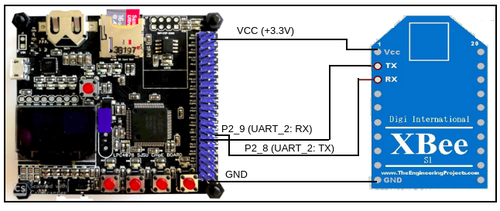
Pin Function SJ2 Joystick Control Board Pin Configuration SJ2 PIN XBEE Module Transmitter TX UART Transmit to Main Board P2_9 VCC VCC Supply VCC 3.3 Joystick VCC VCC 3.3V GND GND GND Vx X-axis ADC Reading for character movement P0_25 Vy Y-axis ADC Reading for character movement P1_30
Printed Circuit Board
Layout & Design
We have designed our Printed Circuit Board using 'AUTODESK EAGLE software', version 9.6.2.The lecture on Eagle PCB provided by Professor Preet provided a good insight about using this software and building a PCB. As suggested during the lecture, we followed Sparkfun Eagle tutorials and libraries while working on the PCB. These resources served as a good source of information for us and made our work easy.
For PCB fabrication, we selected the PCB manufacturer 'JLCPCB' because their production lead-time was less compared to other manufacturers. They had an efficient customer service and faster delivery option that helped us to get our PCBs on time.
Schematic and Board Design of PCB
      1. We created a common PCB design for both of our SJ2 Boards.
      2. The following connectors were used to design a schematic for our design
                 •LED Matrix        - 10-pin series 057 contact pc board low profile headers
                 •SJ2 Board         - 40-pin series 057 contact pc board low profile headers
                 •Joystick          - 5 pin header
                 •MP3 Serial Player - 4 pin header
                 •Xbee              - Adafruit library Xbee Module
Hardware Interface
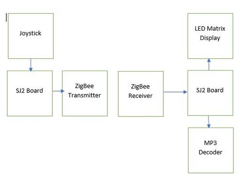
We used two SJ2 boards for this project. One main SJ2 board to drive the LED Matrix Display and the MP3 Decoder, another SJ2 board to collect the control signals from the Analog Joystick connected to it. These signals are wirelessly transmitted from this board to the main SJ2 board driving the LED Display. This communication is achieved using Zigbee over UART.
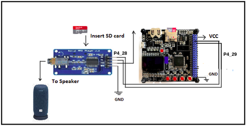
Universal Asynchronous Receiver Transmitter (UART) is also used as an interface to connect the main SJ2 board and MP3 Serial Player. UART_3 is configured for YX5300 MP3 player. Below is the pinout connections between UART and MP3 Serial Player:
Hardware Implementation
LED Matrix
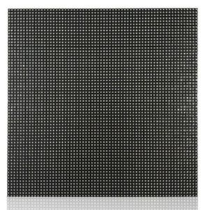
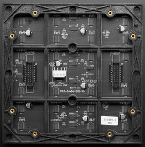
A 64x64 RGB LED Matrix Panel is used as the display for this game. It has 64 rows and 64 columns. It is divided into two 32x64 sections. Each LED pixel can be accessed and controlled individually. A decoder is used to access individual row. One row can be selected at a time using A,B,C,D and E pins. This enables us to select one row in each of the 32X64 sections. Columns are controlled using shift registers, every bit in the shift register controls the corresponding column. On every falling edge of the clock pulse, the values at R1, B1, G1, R2, B2, and G2 pins are stored into the shift register and the register shifts the data by one bit. After this, the data on the shift register is passed onto the individual LED's when both OE and LE pins are set to high.
MP3 Serial Player:
MP3 Serial Player module is a simple MP3 player device which is based on a high quality MP3 audio chip. It can support 8kHz - 48kHz sampling frequency MP3 and WAV file formats. Also, this board has a TF card socket so that a SD card can be inserted that stores audio files. SJTwo board can control this module via UART port, such as switch songs, change the volume and play mode, and so on.
The SD card should be formatted as FAT16 or FAT32 and should have some audio files with .mp3 or .wav formats. If the user wants to create separate folders then those should be created as “01”, “02” and the songs should be with the names 001xxx.mp3/ 002xxx.mp3/ 003xxx.mp3 in those created folders.
Software Implementation:
The module communicates with the microcontroller through commands which are a combination of data and cmd fields. The cmd field allows us to control the module. Commands are available for the functions like Play NEXT_SONG, PREV_SONG, PLAY_WITH_INDEX, etc. The data field is required, the data field is required; this is noted, otherwise it is set to zero and ignored., otherwise it is set to zero and ignored.
Below is the command list followed for this project:
- Next_song 0x01 Play next song.
- Prev_song 0x02 Play previous song.
- Play_with_index 0x03 Play song with index number. Data is the index of the file.
- Volume_up 0x04 Volume increase by one.
- Volume_down 0x05 Volume decrease by one.
- Set_volume 0x06 Set the volume to level specified. Data is the volume level [0..30].
- Set_equalizer 0x07 Set the equalizer to specified level. Data is [0..5] – 0=normal, 1=pop, 2=rock, 3=jazz, 4=classic or 5=base.
- Sng_cycl_play 0x08 Loop play (repeat) specified track. Data is the track number.
- Sel_dev 0x09 Select file storage device. The only valid choice for data is tf (0x02).
- Sleep_mode 0x0a Chip enters sleep mode.
- Wake_up 0x0b Chip wakes up from sleep mode.
- Reset 0x0c Chip reset.
- Play 0x0d Playback restart.
- Pause 0x0e Pause playback.
- Play_folder_file 0x0f Play the file with the specified folder and index number
- Stop_play 0x16 Stop playback.
- Folder_cycle 0x17 Loop playback within specified folder. Data is the folder index.
- Shuffle_play 0x18 Playback shuffle mode. Data is 0 to enable, 1 to disable.
- Set_sngl_cycl 0x19 Set loop play (repeat) on/off for current file. Data is 0 to enable, 1 to disable.
- Set_dac 0x1a Dac on/off control (mute sound). Data is 0 to enable dac, 1 to disable dac (mute).
- Play_w_vol 0x22 Play track at the specified volume. Data hi byte is the track index, low byte is the volume level [0..30].
- Shuffle_folder 0x28 Playback shuffle mode for folder specified. Data high byte is the folder index.
Code Snippet of MP3 module:
 void MP3__command(uint8_t command, uint16_t dat) {
 MP3_buffer[0] = 0x7e;                // starting byte
 MP3_buffer[1] = 0xff;                // version
 MP3_buffer[2] = 0x06;                // the number of bytes of the command without starting byte and ending byte
 MP3_buffer[3] = command;             //
 MP3_buffer[4] = 0x00;                // 0x00 = no feedback, 0x01 = feedback
 MP3_buffer[5] = (uint8_t)(dat >> 8); // datah
 MP3_buffer[6] = (uint8_t)(dat);      // datal
 MP3_buffer[7] = 0xef;                // ending byte
 for (uint8_t i = 0; i < 8; i++)
   uart__polled_put(UART__3, MP3_buffer[i]);
 }
Joystick:
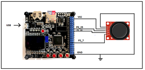
The joystick is similar to two potentiometers connected together , one for the vertical movement (Y-axis), other for horizontal movement (X-axis). The 4 direction output values from the joystick are used to move the fireman positions right, left, up and down. The ADC clock frequency was set to 12MHz.
Features:
- Two independent Potentiometer: one for each axis ( X and Y)
- Auto return to center position
- Low weight
- Cup-type Knob
- Compatible to interface with Arduino or with most microcontrollers
Technical Specifications:
- Operating Voltage: 5V
- Internal Potentiometer value: 10k
- 2.54mm pin interface leads
- Dimensions: 1.57 in x 1.02 in x 1.26 in (4.0 cm x 2.6 cm x 3.2 cm)
- Operating temperature: 0 to 70 °C
Software Implementation:
The joystick communicates with the SJTwo board via ADC pins. Joystick provides two outputs which are X-axis (connected to ADC_2: P0_25 of SJTwo), Y-axis (connected to ADC_4: P1_30 of SJTwo). The outputs at X-axis and Y-axis are taken as inputs for changing the fireman positions. The switch takes the input from the user and is used to fire the water bullets towards the generated fire flames.
ADC Initialization:
 gpio__construct_with_function(GPIO__PORT_0, 25, GPIO__FUNCTION_1); // ADC2
 gpio__construct_as_output(GPIO__PORT_0, 25);
 LPC_IOCON->P0_25 &= ~((1 << 3) | (1 << 4));
 gpio__construct_with_function(GPIO__PORT_1, 30, GPIO__FUNCTION_3); // ADC4
 gpio__construct_as_output(GPIO__PORT_1, 30);
 LPC_IOCON->P1_30 &= ~((1 << 3) | (1 << 4));
Threshold range for different joystick movements:
 if (water_splash_flag == true) {
   control_signal = water_splash;
   water_splash_flag = false;
 } else if (((ValueRx > 1900) && (ValueRx < 3000)) && ((ValueRy > 1900) && (ValueRy < 3000))) {
   control_signal = center;
 } else if ((((ValueRx > 1900) && (ValueRx < 3000)) && (ValueRy < 100))) {
   control_signal = left;
 } else if (((ValueRx > 3000) && (ValueRx < 4096)) && ((ValueRy > 15) && (ValueRy < 200))) {
   control_signal = left_up_diagonal;
 } else if (((ValueRx > 15) && (ValueRx < 200)) && ((ValueRy > 15) && (ValueRy < 200))) {
   control_signal = left_down_diagonal;
 } else if ((ValueRx < 50) && ((ValueRy > 1900) && (ValueRy < 3000))) {
   control_signal = down;
 } else if ((((ValueRx > 1900) && (ValueRx < 3000)) && ((ValueRy > 3000) && (ValueRy < 4096)))) {
   control_signal = right;
 } else if (((ValueRx > 15) && (ValueRx < 100)) && ((ValueRy > 3000) && (ValueRy < 4096))) {
   control_signal = right_down_diagonal;
 } else if ((ValueRx > 3000) && ((ValueRx < 4096)) && (ValueRy > 3000) && ((ValueRy < 4096))) {
   control_signal = right_up_diagonal;
 } else if (((ValueRx > 3000) && (ValueRx < 4096)) && ((ValueRy > 1900) && (ValueRy < 3000))) {
   control_signal = up;
 } else {
   control_signal = center;
 }
 return control_signal;
 }
ZigBee:
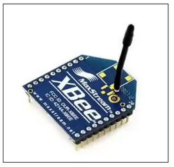
Zigbee is a wireless communication module which use IEEE 802.15.4 standard. 802.15.4 is a IEEE standard for low power applications of radio frequency. Zigbee generally operates in the 2.4GHz range (although there are geographic variations), and supports data ranges from 20 to 250 kbits/s.The transmission distance though, is small compared to the likes of LoRa. It is 10 to 100 m, whereas LoRa can transmit over a few kilometers. Another thing to note is that Zigbee communication doesn’t work very well if there is no line of sight between transmitter and receiver.Even minor obstacles have been observed to significantly degrade the communication. Our project uses two SJTwo boards and these two boards are connected using a ZigBee module on each board. Zigbee can communicate with external devices such as sensors and communication devices. The Zigbee module needs to be configured using XCTU software.
Interface between SJTwo board and ZigBee:
Software Implementation
Transmitter end:
 static void water_splash_task(void *pv) {
   while (1) {
     data = joystick__sendControl();
     // fprintf(stderr, "data=%d\n", data);
     if (!(LPC_GPIO4->PIN & (1 << 28))) {
       water_splash_flag = true;
     }
     uart_lab__polled_put(UART_2, data);    // XBee TX
     fprintf(stderr, "Sent: %i over UART to the other board\n", data);
     vTaskDelay(50);
  }
 }
Receiver end:
 void startup_update_display_delay(void) {
   if (!start_flag) {
     for (int i = 0; i < 90; i++) {
       led_matrix__updateDisplay();
       flameover_xbee_recvr__receive_data(); // XBee RX
       if (joystick_control_signal == 9) {
         start_flag = true;
         i = 100;
         break;
       }
     }
   }
 }
Software Design and Implementation
Game Start screen
At the start of the game, a welcome screen is continously displayed until the player is ready and presses the start key. Only on start key press, the freertos game logic tasks are scheduled.
Game Design and tasks
We used six freertos tasks of different priorities to control the course of the game:
- Game display Task
- Refreshes the screen ie., it clears and updates the screen every 3 milliseconds.
- Draws all the game characters ie., fireman, flames and fireman lives periodically every 3 milliseconds.
- Implements logic to check for level ups, game win or lose status.
- Checks if the fireman was able to successfully put the flames off or if the flames hit the fireman and updates the count of fireman lives based on this.
- Fireman Task
- Keeps track of the direction control data transmitted wirelessly from the joystick device from the other board and accordingly updates Fireman position.
- Also has a logic to update water splash trigger flag when the joystick key press signal is received.
- Water Splash Task
- Reads the water splash trigger flag that has been updated in ‘Fireman Task’ and controls the movement of water splash bullets.
- Plays a water bullet sound track every time water splash bullets are released.
- Flame1 Task and Flame2 Task
- Generates Flames on two horizontal tracks from the left and move them towards the right end unless striked by a water bullet, in which case, the flames burst and are put off.
- Generates random starting row positions for each of these flames.
- Controls the speed of movement of these flames based on the game level.
- Decrements the fireman health every time the fireman is hit by a flame.
Collision detection:
- Flame to Water bullet Collision
- When the water bullet hits the flames, the bullets and flames disappear on the screen indicating the flame was successfully put off. The number of flames put off is incremented for level up and respective flags are set. Burst animation is played at the collision.
- Fireman to Flame Collision
- When the flame hits the fireman for 3 times, fireman's health reduced by 1. Burst animation is played at the collision. And once the fireman's health reduces to 20 from the initial 100, the player loses all lives and loses the game.
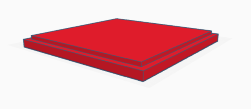
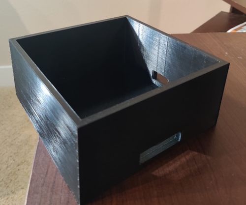
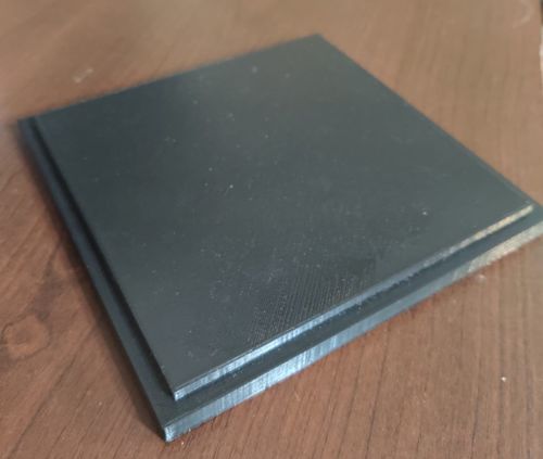
3D Packaging
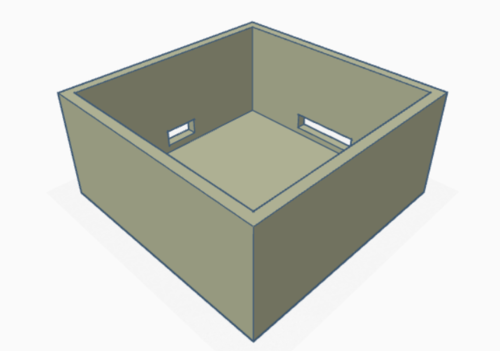
To accomodate the two PCB Boards and the hardware components in one single black box, we created a 3D case with a lid. We designed the 3D design using the AUTODESK TINKERCAD web application and generated the .stl files for 3D print. We did the 3D printing at SJSU library. In order to get the print in less amount of time , we had to correct the infill density and other parameters using Ultimaker Cura application. Finally, by building the 3D case and by enclosing the components inside it, we were able to simulate a good gaming experience.
Testing & Technical Challenges
Testing
Below are the steps taken for testing and verification:
- Verified that the pin connections are correct after hardware integration on PCB
- Verified continuity between the pins.
- Verified that there are no short connections after the PCB fabrication.
- Calibrated the Joystick for precise movements.
- Intensive testing performed to confirm synchronisation of soud effects with the game logic.
Technical Challenges
LED Matrix
- Designing the main character of the game was time consuming as it required proper plotting of pixel data and proper alignment.
- Handling the wiring of the matrix without the PCBs proved to be a great challenge.
- Finding a good refresh rate was crucial for the display. The screen ended up flickering for few refresh rates. The task design had to be curated and the refresh rate had to be reevaluated to mitigate flickering.
- In the initial stages of familiarizing with the LED matrix display, we observed random pixels being lit instead of the desired ones. We referred to online sources to see what we were doing wrong. We later changed our initializing sequence and it started working fine.
MP3 Serial Player and Sound Effects -
- Songs are referenced by folder and by song ‘index’, although it seems that the numeric index is sometimes ignored and the songs played in the order they are stored in the SD card. The documentation is unclear on this and seems to imply both situations. So, even if you plan only one playlist, it is better to keep them in a ’01’ folder and save all the songs to the SD card at the same time.
- Finding the appropriate game sounds for free was tough as most of the sounds were paid.
PCB Designing -
- Placement of components on the schematic and board layout required proper assessment in order to avoid congestion of components while soldering.
Exhausting UART peripherals -
- We initially planned of using only one SJ2 board for the driving the LED display, MP3 Decoder and Joystick. But we exhausted the pins on the SJ2 board with LED Matrix display and MP3 Decoder. So we used another SJ2 board to wirelessly transmit the joystick signals to the main board over zigbee.
Conclusion
This project was a great hands on learning experience on freertos and real time task synchronization. It gives a complete understanding of how to design an entire free rtos based system from scratch. While working with this project, we understood the importance of semaphores, task priorities, stack utilization. It was challenging but we thoroughly enjoyed the process.
Project Video
Project Source Code
References
Acknowledgement
We would like to thank our Professor Preetpal Kang for all the learnings from this course. This course engages the students and gives a hands on experience of everything. We'd also like to thank our ISA team for all the suggestions and timely help with the Project. And a kudos to our entire team, Flame Over. With full support and cooperation from each other, we were successfully able to complete this project as planned.
