Difference between revisions of "F21: Sons of Ultron"
Proj user5 (talk | contribs) (→Schedule) |
Proj user5 (talk | contribs) (→Team Members) |
||
| (128 intermediate revisions by the same user not shown) | |||
| Line 1: | Line 1: | ||
| − | [[File:BUBBLE_TROUBLE. | + | [[File:BUBBLE_TROUBLE.png||600px|caption|right|thumb|Miniclip Game: Bubble Trouble]] |
| + | |||
| + | |||
| + | |||
| + | |||
| + | |||
== '''Bubble Trouble''' == | == '''Bubble Trouble''' == | ||
| − | + | [[File:BubbleTroubleGame.jpg|center|800px|thumb|]] | |
| − | == Abstract == | + | == Team Members == |
| + | <div><ul> | ||
| + | <li style="display: inline-block;vertical-align: top;"> [[File:Rishabh.jpg|thumb|left|250px|[https://www.linkedin.com/in/rishabh-gupta-a56ab5125 <big>Rishabh Gupta</big>]]] </li> | ||
| + | <li style="display: inline-block;vertical-align: top;"> [[File:Saharsh.jpg|thumb|left|250px|[https://www.linkedin.com/in/saharshanuragshivhare <big>Saharsh Anurag Shivhare</big>]]] </li> | ||
| + | <li style="display: inline-block;vertical-align: top;"> [[File:Vilas.jpg|thumb|left|250px|[https://www.linkedin.com/in/vilas-dhuri-b5a9131b5 <big>Vilas Dhuri</big>]]] </li> | ||
| + | </ul></div> | ||
| + | |||
| + | == '''Abstract''' == | ||
Clear all the bubbles and get yourself out of trouble !! “Bubble Trouble” is a fun game where each time you hit a big bubble, it will split up into two smaller ones. Avoid the bubbles as they bounce through the level. Race against time, collect all the traps and power-ups you can use to be the best at this game. Do you have what it takes to be the ultimate bubble shooter?. This is all displayed in the LED matrix acting as the screen. Use your spike gun to pop all the bubbles from the largest to the smallest bits. Can you clear each level?. | Clear all the bubbles and get yourself out of trouble !! “Bubble Trouble” is a fun game where each time you hit a big bubble, it will split up into two smaller ones. Avoid the bubbles as they bounce through the level. Race against time, collect all the traps and power-ups you can use to be the best at this game. Do you have what it takes to be the ultimate bubble shooter?. This is all displayed in the LED matrix acting as the screen. Use your spike gun to pop all the bubbles from the largest to the smallest bits. Can you clear each level?. | ||
| − | == Objectives | + | == '''Objectives''' == |
| − | + | The main objective of this project was to create the “BUBBLE TROUBLE” video game displayed on a 64X64 RGB LED matrix, with one SJ2 board as a graphics processor/matrix controller, and another SJ2 board as a controller. Other objectives are the following: | |
| + | * Design custom PCBs for both the gamepad and matrix controller SJ2 boards. | ||
| + | * Use the FreeRTOS Real-Time Operating System on both SJ2 boards. | ||
| + | * Establish UART communications through Xbee between the two SJ-Two Microcontrollers. | ||
| + | * Create simple coding logic for displaying required characters and game objects. | ||
| + | * Add background music to the game to enhance the gameplay experience. | ||
| − | === Technical Responsibilities | + | == '''Introduction'''== |
| + | * Matrix Controller Board: The matrix controller board is responsible for displaying the graphics of the game, controlling the game logic, playing MP3 tracks based on the current game/menu screen, receiving character movement and button press signals over the Xbee interface. | ||
| + | |||
| + | * GamePad Controller Board: The gamepad controller board is responsible for processing input joystick and button press signals, controlling the character controls logic, sending character movement and button press signals over an Xbee interface. | ||
| + | |||
| + | '''HOW TO PLAY BUBBLE TROUBLE:''' | ||
| + | The main aim of the game is to burst all the bubbles and advance to the next level. | ||
| + | * Using the joystick on the game controller, move the character left or right. | ||
| + | * Shoot arrows using the button on the game controller to burst the bubbles into smaller ones. | ||
| + | * The character must avoid getting hit by the bubbles. | ||
| + | * If the character gets hit by the bubbles it loses one life and the level restarts | ||
| + | * Each level has a time limit to complete it. If all the bubbles are not burst in that time limit the player loses one life. | ||
| + | * With each level the number of balloons and the size of bubbles increase. | ||
| + | |||
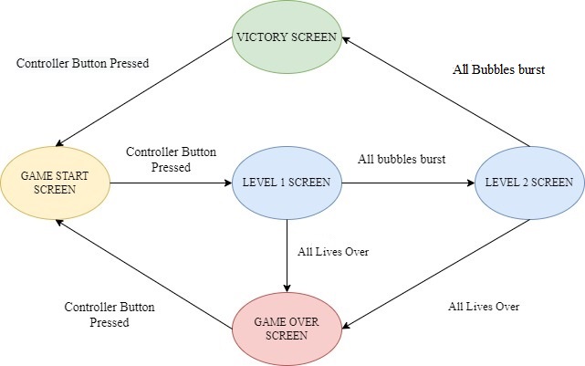
| + | [[File:DATA_FLOW.jpg|center|800px|thumb|Game Flow]] | ||
| + | |||
| + | == '''Technical Responsibilities''' == | ||
{| class="wikitable" style="margin-left: 0px; margin-right: auto;" | {| class="wikitable" style="margin-left: 0px; margin-right: auto;" | ||
|- style="vertical-align: top;" | |- style="vertical-align: top;" | ||
| − | ! colspan="5"| | + | ! colspan="5" scope="col" style="background:#ADD8E6;"|<span style="color:#FFFFFF"> <font size=3> Technical Roles </font></span> |
|- | |- | ||
! style="text-align: left;" | | ! style="text-align: left;" | | ||
| Line 47: | Line 80: | ||
|} | |} | ||
| − | + | == '''Administrative Responsibilities''' == | |
| − | |||
{| class="wikitable" style="margin-left: 0px; margin-right: auto;" | {| class="wikitable" style="margin-left: 0px; margin-right: auto;" | ||
|- style="vertical-align: top;" | |- style="vertical-align: top;" | ||
| − | ! colspan="5"| Administrative Roles | + | ! colspan="5" scope="col" style="background:#ADD8E6;"|<span style="color:#FFFFFF"> <font size=3> Administrative Roles </font></span> |
|- | |- | ||
! style="text-align: left;" | | ! style="text-align: left;" | | ||
| Line 77: | Line 109: | ||
<BR/> | <BR/> | ||
| − | == Schedule == | + | =='''Schedule''' == |
{| class="wikitable" | {| class="wikitable" | ||
|- | |- | ||
| − | ! scope="col"| Week# | + | ! scope="col" style="background:#ADD8E6;"|<span style="color:#FFFFFF"> <font size=3> Week# </font></span> |
| − | ! scope="col"| Start Date | + | ! scope="col" style="background:#ADD8E6;"|<span style="color:#FFFFFF"> <font size=3> Start Date </font></span> |
| − | ! scope="col"| End Date | + | ! scope="col" style="background:#ADD8E6;"|<span style="color:#FFFFFF"> <font size=3> End Date </font></span> |
| − | ! scope="col"| Task | + | ! scope="col" style="background:#ADD8E6;"|<span style="color:#FFFFFF"> <font size=3> Task </font></span> |
| − | ! scope="col"| Status | + | ! scope="col" style="background:#ADD8E6;"|<span style="color:#FFFFFF"> <font size=3> Status </font></span> |
|- | |- | ||
! scope="row"| 1 | ! scope="row"| 1 | ||
| | | | ||
| − | * 10/ | + | * 10/11/2021 |
| − | |||
| | | | ||
| − | * 10/ | + | * 10/17/2021 |
| − | |||
| | | | ||
* Read previous projects, gather information, and discuss among the group members. | * Read previous projects, gather information, and discuss among the group members. | ||
* Create a GitLab repository for the project. | * Create a GitLab repository for the project. | ||
| | | | ||
| + | * <span style="color:green">Completed</span> | ||
* <span style="color:green">Completed</span> | * <span style="color:green">Completed</span> | ||
|- | |- | ||
! scope="row"| 2 | ! scope="row"| 2 | ||
| | | | ||
| − | *10/ | + | *10/18/2021 |
| | | | ||
| − | * | + | *10/24/2021 |
| | | | ||
| − | + | * Order necessary parts | |
| − | *Order necessary parts | + | * Distributing project tasks among group members |
| | | | ||
| + | * <span style="color:green">Completed</span> | ||
* <span style="color:green">Completed</span> | * <span style="color:green">Completed</span> | ||
|- | |- | ||
| Line 115: | Line 147: | ||
*10/25/2021 | *10/25/2021 | ||
| | | | ||
| − | * | + | *10/31/2021 |
| | | | ||
*Read and familiarize with LED Matrix Datasheet. | *Read and familiarize with LED Matrix Datasheet. | ||
| Line 122: | Line 154: | ||
| | | | ||
* <span style="color:green">Completed</span> | * <span style="color:green">Completed</span> | ||
| − | + | * <span style="color:green">Completed</span> | |
| − | |||
|- | |- | ||
! scope="row"| 4 | ! scope="row"| 4 | ||
| | | | ||
| − | * | + | *11/01/2021 |
| | | | ||
| − | * 11/ | + | *11/7/2021 |
| | | | ||
| − | * | + | * Finalize wiki schedule |
| − | *Game Start-up Screen | + | * Developing graphics driver for LED matrix and implementing initial game objects |
| + | * Designing Game Start-up Screen and Game Over screen | ||
| + | * Designing PCB and Circuit Simulation in Eagle Tool | ||
| | | | ||
| − | * <span style="color: | + | * <span style="color:green">Completed</span> |
| + | * <span style="color:green">Completed</span> | ||
| + | * <span style="color:green">Completed</span> | ||
| + | * <span style="color:Green">Completed</span> | ||
|- | |- | ||
! scope="row"| 5 | ! scope="row"| 5 | ||
| | | | ||
| − | *11/ | + | *11/8/2021 |
| − | *11/ | + | | |
| + | *11/14/2021 | ||
| | | | ||
| − | * | + | * Joystick integration and Button for shooting |
| − | * | + | * Implementing Character Movement through Joystick using UART |
| − | + | * Implementing Arrow shooting logic | |
| − | * | + | * Designing and Implementing Ball Trajectory and bounce logic |
| − | * | ||
| | | | ||
* <span style="color:green">Completed</span> | * <span style="color:green">Completed</span> | ||
| − | * <span style="color: | + | * <span style="color:green">Completed</span> |
| + | * <span style="color:green">Completed</span> | ||
| + | * <span style="color:green">Completed</span> | ||
|- | |- | ||
! scope="row"| 6 | ! scope="row"| 6 | ||
| − | |||
| − | |||
| | | | ||
| − | *11/ | + | * 11/15/2021 |
| + | |||
| + | | | ||
| + | * 11/21/2021 | ||
| | | | ||
| − | * Game logic development | + | * Implementing Ball Splitting logic |
| + | * Developing Screen Transition from the game screen to level | ||
| + | * Game logic development | ||
* Testing and debugging the game logic | * Testing and debugging the game logic | ||
| − | |||
| | | | ||
| − | * <span style="color: | + | * <span style="color:green">Completed</span> |
| − | * <span style="color: | + | * <span style="color:green">Completed</span> |
| − | * <span style="color: | + | * <span style="color:green">Completed</span> |
| + | * <span style="color:green">Completed</span> | ||
|- | |- | ||
! scope="row"| 7 | ! scope="row"| 7 | ||
| | | | ||
| − | * 11/ | + | * 11/22/2021 |
| | | | ||
| − | * 11/ | + | * 11/28/2021 |
| | | | ||
| − | * | + | * Configuring Xbee Modules |
| − | * | + | * Integrating Xbee for wireless remote control and character Movement |
| + | * LED Matrix Score and Lives Bar | ||
| + | * Implementing Game timer | ||
| + | * Implementing game logic for the ball hitting the character | ||
| + | * Finalizing PCB design in software and order PCB | ||
| + | * Integrating MP3 decoder into the game | ||
| + | * Integrating game sounds with game logic | ||
| | | | ||
| − | * <span style="color: | + | * <span style="color:green">Completed</span> |
| − | * <span style="color: | + | * <span style="color:green">Completed</span> |
| + | * <span style="color:green">Completed</span> | ||
| + | * <span style="color:green">Completed</span> | ||
| + | * <span style="color:green">Completed</span> | ||
| + | * <span style="color:green">Completed</span> | ||
| + | * <span style="color:green">Completed</span> | ||
| + | * <span style="color:green">Completed</span> | ||
|- | |- | ||
! scope="row"| 8 | ! scope="row"| 8 | ||
| | | | ||
| − | * 11/ | + | * 11/29/2021 |
| | | | ||
| − | * 12/ | + | * 12/05/2021 |
| | | | ||
| − | + | * Designing and integrating transition to level two and music | |
| − | * | + | * Developing level-two logic |
| + | * Designing Game Win and Game Lose screen | ||
| + | * Implementing the score-board and health count | ||
| + | * Designing game timer and score-count relationship | ||
| + | * Testing power supply module | ||
| + | * Buying PCB parts from Anchor Electronics | ||
* Finalizing the video game | * Finalizing the video game | ||
| − | * Update the wiki page | + | * Integrate subsystem |
| + | * Update the wiki page | ||
| | | | ||
| − | * <span style="color: | + | * <span style="color:green">Completed</span> |
| − | * <span style="color: | + | * <span style="color:green">Completed</span> |
| − | * <span style="color: | + | * <span style="color:green">Completed</span> |
| + | * <span style="color:green">Completed</span> | ||
| + | * <span style="color:green">Completed</span> | ||
| + | * <span style="color:green">Completed</span> | ||
| + | * <span style="color:green">Completed</span> | ||
| + | * <span style="color:green">Completed</span> | ||
| + | * <span style="color:green">Completed</span> | ||
| + | * <span style="color:green">Completed</span> | ||
|- | |- | ||
! scope="row"| 9 | ! scope="row"| 9 | ||
| | | | ||
| − | * 12/ | + | * 12/06/2021 |
| | | | ||
| − | * 12/ | + | * 12/12/2021 |
| | | | ||
| − | * Address bugs during testing of integrated system | + | * Address bugs during testing of the integrated system |
| − | * Test | + | * Test game-flow |
| + | * Test PCB and make connections | ||
| + | * Code Cleaning and Removing dead code | ||
| + | * Assemble the Matrix and Controller Enclosure | ||
| | | | ||
| − | * <span style="color: | + | * <span style="color:green">Completed</span> |
| − | * <span style="color: | + | * <span style="color:green">Completed</span> |
| − | * <span style="color: | + | * <span style="color:green">Completed</span> |
| + | * <span style="color:green">Completed</span> | ||
| + | * <span style="color:green">Completed</span> | ||
|- | |- | ||
! scope="row"| 10 | ! scope="row"| 10 | ||
| Line 223: | Line 294: | ||
*Update the wiki page. | *Update the wiki page. | ||
| | | | ||
| − | * <span style="color: | + | * <span style="color:green">Completed</span> |
| − | * <span style="color: | + | * <span style="color:green">Completed</span> |
| − | * <span style="color: | + | * <span style="color:green">Completed</span> |
| − | * <span style="color: | + | * <span style="color:green">Completed</span> |
|- | |- | ||
|} | |} | ||
| Line 233: | Line 304: | ||
<BR/> | <BR/> | ||
| − | == Parts List & Cost == | + | =='''Bill Of Materials'''== |
| − | + | <font size = 4> Parts List & Cost </font> | |
| + | {| class="wikitable" style="margin-left: 0px; margin-right: auto;" | ||
| + | |- | ||
| + | ! scope="col" style="background:#ADD8E6;"|<span style="color:#FFFFFF"> <font size=3> Item# </font></span> | ||
| + | ! scope="col" style="background:#ADD8E6;"|<span style="color:#FFFFFF"> <font size=3>Part Description </font></span> | ||
| + | ! scope="col" style="background:#ADD8E6;"|<span style="color:#FFFFFF"> <font size=3>Part Model & Vendor </font></span> | ||
| + | ! scope="col" style="background:#ADD8E6;"|<span style="color:#FFFFFF"> <font size=3>Quantity </font></span> | ||
| + | ! scope="col" style="background:#ADD8E6;"|<span style="color:#FFFFFF"> <font size=3>Cost </font></span> | ||
| + | |- | ||
| + | ! scope="row"| 1 | ||
| + | | Microcontroller Boards | ||
| + | | [https://www.amazon.com/Generic-SJTwo-SJ2-SJSU/dp/B08G9LRPZ8/ref=sr_1_4?keywords=sj2+board&qid=1638600916&sr=8-4 SJ2 Boards (Purchased from Preet Kang)] | ||
| + | | 2 | ||
| + | | $100.00 | ||
| + | |- | ||
| + | ! scope="row"| 2 | ||
| + | | LED Matrix Display | ||
| + | | [https://www.adafruit.com/product/3649 Adafruit RGB LED Matrix Panel - 64x64] | ||
| + | | 1 | ||
| + | | $87.95 | ||
| + | |- | ||
| + | ! scope="row"| 3 | ||
| + | | PCB | ||
| + | | [https://jlcpcb.com/ JLC PCB] | ||
| + | | 5 | ||
| + | | $18.00 | ||
| + | |- | ||
| + | ! scope="row"| 4 | ||
| + | | Electronics Fun Kit & Power Supply Module | ||
| + | | [https://www.amazon.com/ELEGOO-Electronics-Potentiometer-tie-Points-Breadboard/dp/B01ERPEMAC/ref=sr_1_1?keywords=electronics+fun+kit&qid=1638603001&sr=8-1 ELEGOO Upgraded Electronics Fun Kit] | ||
| + | | 2 | ||
| + | | $7.56 | ||
| + | |- | ||
| + | ! scope="row"| 5 | ||
| + | | MP3 Decoder | ||
| + | | [https://www.amazon.com/HiLetgo-YX5300-Control-Serial-Arduino/dp/B0725RHR4D/ref=sr_1_6?crid=6LU06UQ364LS&keywords=hiletgo+mp3&qid=1638600984&sprefix=hiletgo+mp3%2Caps%2C220&sr=8-6 HiLetgo YX5300 UART Control Serial MP3 Music Player Module] | ||
| + | | 1 | ||
| + | | $6.99 | ||
| + | |- | ||
| + | ! scope="row"| 6 | ||
| + | | Power Adapter for LED Matrix | ||
| + | | [https://www.amazon.com/Belker-Adjustable-Universal-Household-Electronics/dp/B08LKRYFT6/ref=sr_1_1_sspa?crid=38ELM8WZ2X8T&keywords=belker+universal+ac+adapter&qid=1638603156&sprefix=belker+universal+%2Caps%2C238&sr=8-1-spons&psc=1&spLa=ZW5jcnlwdGVkUXVhbGlmaWVyPUExVko5T0JZTE9BMzkzJmVuY3J5cHRlZElkPUEwMzU2ODc3M0hNRlMzV1EyTk5RMiZlbmNyeXB0ZWRBZElkPUEwMDY0OTIxMVY1TEYwMTBQSVhCTyZ3aWRnZXROYW1lPXNwX2F0ZiZhY3Rpb249Y2xpY2tSZWRpcmVjdCZkb05vdExvZ0NsaWNrPXRydWU= Belker 36W Adapter (Borrowed from TA)] | ||
| + | | 1 | ||
| + | | $0.00 | ||
| + | |- | ||
| + | ! scope="row"| 7 | ||
| + | | XBee Module | ||
| + | | [https://www.amazon.com/XBee-2mW-Wire-Antenna-ZigBee/dp/B007R9U1QA/ref=sr_1_5?keywords=s1+international+xbee&qid=1638603432&sr=8-5 XBee 2mW Wire Antenna - Series 2C (ZigBee Mesh)(Borrowed from Prof. Preet)] | ||
| + | | 2 | ||
| + | | $0.00 | ||
| + | |- | ||
| + | ! scope="row"| 8 | ||
| + | | Joystick | ||
| + | | [https://www.amazon.com/gp/product/B00P7QBGD2/ref=ppx_yo_dt_b_asin_title_o01_s00?ie=UTF8&psc=1 HiLetgo Game Joystick Sensor Game Controller] | ||
| + | | 1 | ||
| + | | $4.89 | ||
| + | |- | ||
| + | ! scope="row"| 9 | ||
| + | | Push Button Switch | ||
| + | | [https://anchor-electronics.com/ Anchor Electronics] | ||
| + | | 1 | ||
| + | | $1.00 | ||
| + | |- | ||
| + | ! scope="row"| 10 | ||
| + | | Jumper Cables | ||
| + | | [https://anchor-electronics.com/ Anchor Electronics] | ||
| + | | 1 | ||
| + | | $7.00 | ||
| + | |- | ||
| + | ! scope="row"| 11 | ||
| + | | Female headers for SJ2-PCB Connection | ||
| + | | [https://www.google.com/maps/dir/San+Jos%C3%A9+State+University,+Washington+Sq,+San+Jose,+CA/anchor+electronics/@37.354066,-121.9429301,13z/data=!3m2!4b1!5s0x808fca25bba0d49f:0x7bbecf700459b959!4m13!4m12!1m5!1m1!1s0x808fccb864de43d5:0x397ffe721937340e!2m2!1d-121.8810715!2d37.3351874!1m5!1m1!1s0x808fca25ba26dfd5:0xc0ca43e28395709a!2m2!1d-121.960719!2d37.369187 Anchor Electronics] | ||
| + | | 1 | ||
| + | | $2.50 | ||
| + | |- | ||
| + | ! scope="row"| 12 | ||
| + | | Ribbon Cable Connector for LED Matrix-PCB Connection | ||
| + | | Anchor Electronics | ||
| + | | 1 | ||
| + | | $1.00 | ||
| + | |- | ||
| + | ! scope="row"| 13 | ||
| + | | Soldering Wire & 18 Gauge Wire | ||
| + | | Anchor Electronics | ||
| + | | 1 | ||
| + | | $3.00 | ||
| + | |- | ||
| + | ! scope="row"| 14 | ||
| + | | Copper Board for Game Controller Connections | ||
| + | | Anchor Electronics | ||
| + | | 1 | ||
| + | | $4.00 | ||
| + | |- | ||
| + | ! scope="row"| | ||
| + | | | ||
| + | | Total Cost | ||
| + | | 22 | ||
| + | | $240.89 | ||
| + | |- | ||
| + | |} | ||
| + | <BR/> | ||
| + | |||
| + | = '''Design & Implementation'''= | ||
| + | == '''PIN CONFIGURATION''' == | ||
| + | <div><ul> | ||
| + | <li style="display: inline-table;"> | ||
| + | {| class="wikitable" style="width: 100%" | ||
| + | |- | ||
| + | ! scope="col" style="background:#ADD8E6;"|<span style="color:#FFFFFF"> <font size=3> Pin# </font></span> | ||
| + | ! scope="col" style="background:#ADD8E6;"|<span style="color:#FFFFFF"> <font size=3> SJ2 Main Board - LED Matrix Pin Configuration </font></span> | ||
| + | ! scope="col" style="background:#ADD8E6;"|<span style="color:#FFFFFF"> <font size=3> SJ-2 PIN </font></span> | ||
| + | |- | ||
| + | |||
| + | ! scope="row"| R1 | ||
| + | | PIN for Red terminal of RGB LED for the upper half of LED Matrix | ||
| + | ! P0_0 | ||
| + | |- | ||
| + | ! scope="row"| G1 | ||
| + | | PIN for Green terminal of RGB LED for the upper half of LED Matrix | ||
| + | ! P0_1 | ||
| + | |- | ||
| + | ! scope="row"| B1 | ||
| + | | PIN for Blue terminal of RGB LED for the upper half of LED Matrix | ||
| + | ! P2_2 | ||
| + | |- | ||
| + | ! scope="row"| R2 | ||
| + | | PIN for Red terminal of RGB LED for the lower half of LED Matrix | ||
| + | ! P2_4 | ||
| + | |- | ||
| + | ! scope="row"| G2 | ||
| + | | PIN for Green terminal of RGB LED for the lower half of LED Matrix | ||
| + | ! P2_5 | ||
| + | |- | ||
| + | ! scope="row"| B2 | ||
| + | | PIN for Blue terminal of RGB LED for the lower half of LED Matrix | ||
| + | ! P2_6 | ||
| + | |- | ||
| + | ! scope="row"| A | ||
| + | | Mux pin for row selection | ||
| + | ! P2_7 | ||
| + | |- | ||
| + | ! scope="row"| B | ||
| + | | Mux pin for row selection | ||
| + | ! P2_8 | ||
| + | |- | ||
| + | ! scope="row"| C | ||
| + | | Mux pin for row selection | ||
| + | ! P2_9 | ||
| + | |- | ||
| + | ! scope="row"| D | ||
| + | | Mux pin for row selection | ||
| + | ! P0_16 | ||
| + | |- | ||
| + | ! scope="row"| E | ||
| + | | Mux pin for row selection | ||
| + | ! P0_15 | ||
| + | |- | ||
| + | ! scope="row"| OE | ||
| + | | Output Enable | ||
| + | ! P1_28 | ||
| + | |- | ||
| + | ! scope="row"| LATCH | ||
| + | | Data Latch | ||
| + | ! P1_29 | ||
| + | |- | ||
| + | ! scope="row"| CLK | ||
| + | | Clock Signal | ||
| + | ! P0_17 | ||
| + | |- | ||
| + | |||
| + | ! scope="row"| | ||
| + | ! scope="col" | MP3 Decoder | ||
| + | | | ||
| + | |- | ||
| + | ! scope="row"| RX | ||
| + | | UART Receive From MP3 Decoder | ||
| + | ! P2_1 | ||
| + | |- | ||
| + | ! scope="row"| TX | ||
| + | | UART Send Command from SJ-2 Main Board | ||
| + | ! P2_0 | ||
| + | |- | ||
| + | |||
| + | ! scope="row"| | ||
| + | ! scope="col"| XBEE Module Receiver | ||
| + | | | ||
| + | |- | ||
| + | |||
| + | ! scope="row"| RX | ||
| + | | UART Receive From Game Controller | ||
| + | ! P0_11 | ||
| + | |- | ||
| + | ! scope="row"| VCC | ||
| + | | VCC Supply | ||
| + | ! VCC 3.3 | ||
| + | |- | ||
| + | |} | ||
| + | </li> | ||
| + | <li style="display: inline-table;"> | ||
| + | {| class="wikitable" style="width: 100%" | ||
| + | |- | ||
| + | ! scope="col" style="background:#ADD8E6;"|<span style="color:#FFFFFF"> <font size=3> Pin# </font></span> | ||
| + | ! scope="col" style="background:#ADD8E6;"|<span style="color:#FFFFFF"> <font size=3> Controller Board Pin Configuration </font></span> | ||
| + | ! scope="col" style="background:#ADD8E6;"|<span style="color:#FFFFFF"> <font size=3> uC PIN </font></span> | ||
| + | |- | ||
| + | |||
| + | |||
| + | ! scope="row"| | ||
| + | ! scope="col" | XBEE Module Transmitter | ||
| + | | | ||
| + | |- | ||
| + | |||
| + | ! scope="row"| TX | ||
| + | | UART Transmit to Main Board | ||
| + | ! P0_10 | ||
| + | |- | ||
| + | ! scope="row"| VCC | ||
| + | | VCC Supply | ||
| + | ! VCC 3.3 | ||
| + | |- | ||
| + | |||
| + | ! scope="row"| | ||
| + | ! scope="col" |Joystick | ||
| + | | | ||
| + | |- | ||
| + | |||
| + | ! scope="row"| VCC | ||
| + | | VCC | ||
| + | ! 3.3V | ||
| + | |- | ||
| + | ! scope="row"| GND | ||
| + | | GND | ||
| + | ! GND | ||
| + | |- | ||
| + | ! scope="row"| Vx | ||
| + | | X-axis ADC Reading for character movement | ||
| + | ! P0_25 | ||
| + | |- | ||
| + | |||
| + | ! scope="row"| | ||
| + | ! scope="col" | Push Button | ||
| + | | | ||
| + | |- | ||
| + | ! scope="row"| I/0 Pin | ||
| + | | Arrow Shooting | ||
| + | ! P1_29 | ||
| + | |- | ||
| + | |||
| + | |} | ||
| + | </li> | ||
| + | </ul></div> | ||
| + | |||
| + | == '''RGB Led Matrix''' == | ||
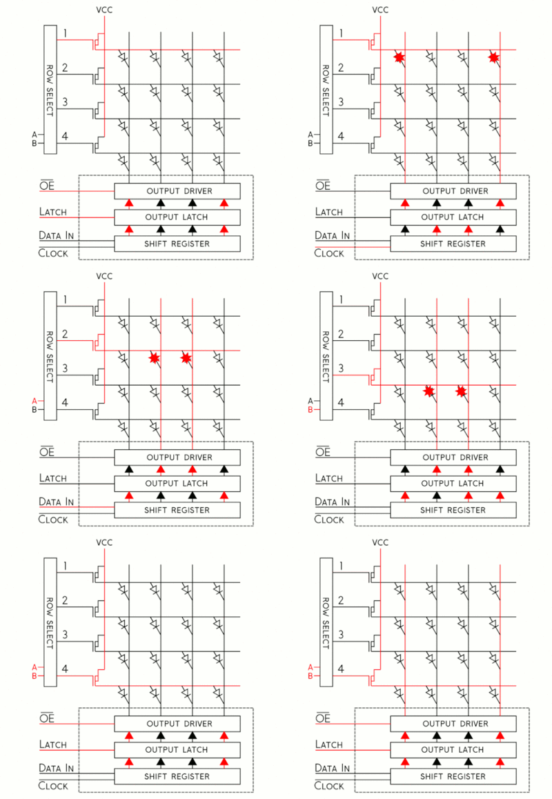
| + | A 64x64 RGB LED Matrix Panel with a scan rate of 1:32 is used as a display in this project. The LED matrix panel features 4096 RGB LEDs that can be individually controlled and addressed. Because connecting 4069 LEDs to the SJ-two board would be impossible due to a lack of GPIOs, this LED Matrix uses only 13 digital GPIOs to enable full control of each individual LED. The LED matrix accomplishes this by selecting the rows with a decoder and enabling the desired color on the selected column with a 64-bit shift register. When the row selection is low, data is clocked into the shift register to choose the columns. Each color of the LED is controlled by one bit of the shift register in this 64x64 LED matrix, which contains six 64-bit shift registers for R1, G1, B1 R2, G2, B2. Because this display employs daisy-chained shift registers, there is no way to control each LED via PWM, hence the display can only display 8 colors. The top half (Rows 0-31) and the bottom half (Rows 32-63) of the LED matrix are controlled by 5:32 decoders, as shown in the diagram below. These decoders are used for row selection and have a 5-bit input for each line A, B, C, D, and E. | ||
| + | |||
| + | Steps to light a LED on the matrix: | ||
| + | # Using three bits, represent the color you want to display on the board. | ||
| + | # Determine if the LED you to wish to light is on the UPPER or LOWER side of the board, and adjust RGB1 or RGB2 pins accordingly. | ||
| + | # Toggle the CLK to set the bits and clock them in with the rest of the LEDs (You can set the other LEDs to be off by clocking in zero) | ||
| + | # Disable Output and set Latch High once a full row has been entered. | ||
| + | # Specify the row your target LED is on using the A, B, C, D, E pins. | ||
| + | # Set the Latch to a low setting and re-enable the Output. | ||
| + | |||
| + | [[File:BubbleTrouble.gif|thumb|center|400px|LED selection]] | ||
| + | |||
| + | =='''PCB DESIGN'''== | ||
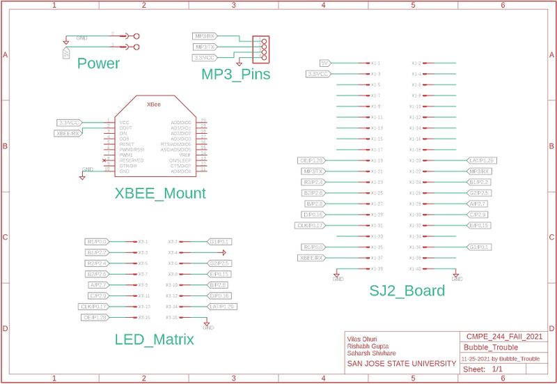
| + | We chose Eagle AutoDesk as our PCB designing software since we got its free license for a year after registering with university email-id. The routing was done manually to create a PCB from a schematic. We designed one PCB, one for our game for our matrix controller. First, we created separate schematics for the controller that included all connections. We included the XBee mount available in the Adafruit library that enabled us an easy connection to the module. For MP3 we directly used male headers whose connection is mapped from the underside of the PCB. Once our schematics were done and we checked it several times. We would like to give a special mention to our roommate Pushkar who is quite familiar with Eagle AutoDesk. He helped us to cross-check the connection and provided us with tips to do better routing.PCB was sent to fabrication to JLCPCB China which provided PCB with an order of 5 and 2 layers of PCB and common grounded the rest of the copper area. | ||
| + | |||
| + | [[File:bob.jpg|center|800px|thumb|Matrix Board PCB Schematic]] | ||
| + | |||
| + | <br> | ||
| + | <div><ul> | ||
| + | |||
| + | {| style="margin-left: auto; margin-right: auto; border: none;" | ||
| + | |[[File:tp.jpg|thumb|none|400px|PCB Top Layer]] | ||
| + | | | ||
| + | |[[File:bt.jpg|thumb|none|400px|PCB Bottom Layer]] | ||
| + | | | ||
| + | |} | ||
| + | |||
| + | [[File:brd.jpg|center|500px|thumb|BRD Image]] | ||
| + | |||
| + | == '''Elegoo Power Supply Module''' == | ||
| + | Rather than supplying power to the SJ-two board, led matrix, and MP3 decoder separately we decide to use the Power supply Module that came with the ELEGOO Upgraded Electronics Fun Kit. This supply module accepts input through a barrel jack from a battery, a 12V adapter, or any other source, and provides to our circuit a 5V as per our requirements. This module provides an inexpensive and convenient way to convert a 7-12V wall bug into 5V and 3.3V to power a solderless breadboard setup. The maximum output current is 700mA. One 5V connecter will go to the Vcc of the SJ-two board whereas 5V will be used to drive the 64x64 led matrix. | ||
| + | |||
| + | [[File:Power_Module_Bubble_trouble.jpg||center|500px|thumb|Power Module]] | ||
| + | |||
| + | == '''LED Matrix and Controller Board Enclosure''' == | ||
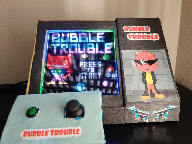
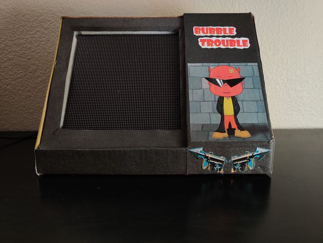
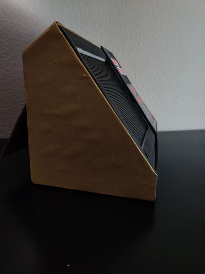
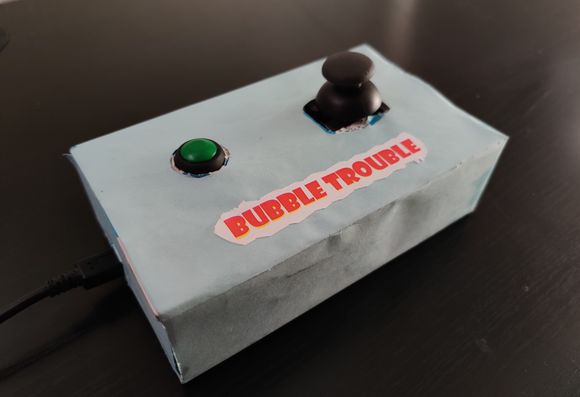
| + | We designed our LED matrix enclosure and controller board enclosure from the boxes available to us. To give the player the maximum immersive experience we have placed our matrix at an angle. The player can sit back, relax and play the arcade game quite easily as the controller board is not connected to the matrix enclosure. The controller board has its own enclosure and the communication between the board takes place through the XBee module. | ||
| + | |||
| + | {| style="margin-left: auto; margin-right: auto; border: none;" | ||
| + | |[[File:FrontView_bubble.jpg|thumb|none|650px|Enclosure Front View]] | ||
| + | | | ||
| + | |[[File:SideView_bubble.jpg|thumb|none|400px|Enclosure Side View]] | ||
| + | | | ||
| + | |} | ||
| + | |||
| + | [[File:controller.jpg|center|580px|thumb|Controller Enclosure]] | ||
| + | |||
| + | == '''MP3 Decoder''' == | ||
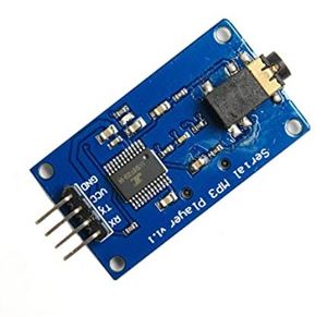
| + | This module is a kind of simple MP3 player device which is based on a high-quality MP3 audio chip---YX5300. It can support 8k Hz ~ 48k Hz sampling frequency MP3 and WAV file formats. There is a TF card socket on board, so you can plug the micro SD card that stores audio files. MCU can control the MP3 playback state by sending commands to the module via the UART port, such as switching songs, changing the volume, etc. | ||
| + | [[File:MP3_Decoder_board.JPG|300px|thumb|center|Serial MP3 Player]] | ||
| − | == Design | + | ==== Hardware Design ==== |
| − | The | + | The MP3 decoder module uses 4 pins namely UART Tx, UART Rx, VCC, and GND. The module required 3.3V to power up which has been supplied from the SJ2 board. We have configured UART1 pins on the SJ2 board for sending commands to the decoder. The baud rate for this UART communication has been set to 9600 bps. This decoder also has a 3.5mm audio jack that has been connected to a speaker. |
| + | [[File:MP3_Decoder_SJ2_Connection.JPG|700px|thumb|center|Connection diagram of MP3 decoder to SJ2 board.]] | ||
| − | === | + | ==== Software Design ==== |
| − | |||
| − | + | [[File:MP3_Initialization.png|700px|thumb|center|MP3 Initialization]] | |
| − | |||
| − | |||
| − | |||
| − | + | The command that we are using in our Bubble Trouble project is to play the music by accessing its index from the SD card. The function that sends this command is called play_music_at_index in our code. Before sending the command to play music at a certain index, we need to send the command [Select device] first. Serial MP3 Player only supports micro SD cards, so you should send “7E FF 06 09 00 00 02 EF” as described in the datasheet. Also, the commands are being sent using UART1 and the function uart__polled_put. | |
| − | |||
| − | + | [[File:MP3_Flowchart.png|700px|thumb|center|MP3 Flowchart]] | |
| − | |||
| − | |||
| − | + | == '''Controller Board and Main Board Communication''' == | |
| + | With an XBee Explorer connected between your computer and your XBee, and with the help of the X-CTU software, you can easily configure XBees, test connections, and pass data between your computer and remote XBees. X-CTU is free software, provided by Digi (the manufacturer of XBee), which we use to configure and manage XBees and test XBee networks. The SparkFun website linked, [https://learn.sparkfun.com/tutorials/exploring-xbees-and-xctu/all here], gives a perfect step-by-step guide to configuring the Xbees as transmitter and receiver. | ||
| + | The controller board consists of the joystick, button press, and Xbee module. The character movement is controlled using a joystick whereas the button presses the shoot arrow. The joystick reading using is taken using ADC. Rather than reading a single value every time we have to enable burst mode on ADC that does repeated conversion at 400khz.This data is then sent from the controller board over to the mainboard (the one that has the game logic and led drivers) using Xbee. After the data is received at the receiver end it is sent over UART. The A0-A6 bits of the UART frame is the joystick ADC reading whereas the A7 bit of the frame is the button pressed data. If the button is not being pressed then blank data is sent. A UART interrupt is generated, which invokes an ISR which sends data into the queue. Now the task that is sleeping on the queue wakes up and depending on the data does the character movement. | ||
| − | === < | + | [[File:XBee_Module_Communication.jpg|875px|thumb|center|Depiction of Communication Between Boards]] |
| − | + | ||
| + | Game Controller reading data from joystick and sending to UART logic | ||
| + | <pre> | ||
| + | void read_joystick_and_send(void *p) { | ||
| + | while (1) { | ||
| + | uint16_t joystick_reading = adc__get_channel_reading_with_burst_mode(ADC__CHANNEL_2); | ||
| + | joystick_reading = (joystick_reading * 125) / 4095; | ||
| + | if (!(LPC_GPIO1->PIN & (1 << 31))) | ||
| + | joystick_reading |= 1 << 7; | ||
| + | uart_lab__polled_put(2, joystick_reading); | ||
| + | vTaskDelay(5); | ||
| + | } | ||
| + | } | ||
| + | </pre> | ||
| + | |||
| + | == '''Game Logic''' == | ||
| + | |||
| + | === '''Ball Trajectory''' === | ||
| + | Bubble shooter uses an intelligent mechanism for the ball jumping. This makes user perceive the game ball jumping almost as real ball jumping and give them the best playing experience. In order to achieve that we have designed a ball jumping logic that follows a parabolic equation. The parabolic equation and graph are shown below: | ||
| + | |||
| + | [[File:Ball_Trajectory.png|700px|thumb|center|Ball Trajectory Graph]] | ||
| + | |||
| + | As the game starts, we have set some initial ball coordinates from where the ball starts its trajectory. By using these staring coordinates of row and column, we then derive the parabolic path which this ball will follow. For deriving the equation, we have used 3 variables, which play the role of the start point slope, curvature and the height of the ball jump. These variables are defined as below: | ||
| + | |||
| + | Height Offset (z): As the name suggests, it is the distance between the maximum height our ball will jump and the upper wall. With ball size, its tendency to jump changes. So heavier ball jumps more as compared to light ball and we change height offset accordingly. | ||
| + | Curvature (b): This decides the curvature of the trajectory. By increasing its value, the parabola keeps getting flat. We have given a constant value for this variable. | ||
| + | Start (a): This value basically means which trajectory our ball will follow if given a start point coordinates, curvature and height offset. It is one of the most important variable as we update this variable, whenever we want to change the trajectory of the ball. | ||
| + | |||
| + | When ball is moving forward: | ||
| + | <pre> | ||
| + | √((Row-Height Offset)*Curvature)+Column | ||
| + | </pre> | ||
| + | When ball is moving backwards: | ||
| + | <pre> | ||
| + | Column- √((Row-Height Offset)*Curvature) | ||
| + | </pre> | ||
| + | Once the variables are defined, we now get the row coordinates by incrementing the column coordinates and feeding that to the derived parabolic equation which further updates the row coordinates. | ||
| + | <pre> | ||
| + | Row = 〖(Column – Start)〗^2/Curvature+Height Offset | ||
| + | </pre> | ||
| + | Now, this methodology was enough to make the ball seem a little close to the parabolic curve. However, on 64x64 LED matrix this did not seem to be an exact parabola and gives stairs like curvature. In order to solve this problem, we designed an algorithm to only display when there is a change in a row while columns keep incrementing. By doing this, our ball does not follow a ramp pattern and seems to be moving in a parabolic slope. | ||
| + | |||
| + | Important Equations: | ||
| + | <pre> | ||
| + | int get_start_value(int row, int col, int height_offset) { | ||
| + | return (sqrt((row - height_offset) * 5) + col); | ||
| + | } | ||
| + | |||
| + | int get_start_value_reverse(int row, int col, int height_offset) { | ||
| + | if ((col - sqrt((row - height_offset) * 5)) > 0) | ||
| + | return (col - sqrt((row - height_offset) * 5)); | ||
| + | else | ||
| + | return (sqrt((row - height_offset) * 5) - col); | ||
| + | } | ||
| + | |||
| + | void parabolic_curve(int *row, int column, int start, int height_offset) { | ||
| + | *row = (((column - start) * (column - start)) / 5) + height_offset; | ||
| + | } | ||
| + | </pre> | ||
| + | |||
| + | One of the balls trajectory logic: | ||
| + | <pre> | ||
| + | static void logic_ball_jumping1(void *p) { | ||
| + | while (1) { | ||
| + | int kill_this_task = 0; | ||
| + | static int temp_col = 0; | ||
| + | if (screen_transition && start_ball_2) { | ||
| + | int temp_row; | ||
| + | if (temp_col + ball[0].max_width >= 60) { | ||
| + | ball[0].direction = 1; | ||
| + | } else if (temp_col <= 3) { | ||
| + | ball[0].direction = 0; | ||
| + | } | ||
| + | if (ball[0].direction) | ||
| + | parabolic_curve(&temp_row, temp_col--, ball[0].start, ball[0].height_offset); | ||
| + | else | ||
| + | parabolic_curve(&temp_row, temp_col++, ball[0].start, ball[0].height_offset); | ||
| + | if (temp_row != ball[0].row_pos) { | ||
| + | display_ball(ball[0].row_pos, ball[0].col_pos, ball_size_1, BLACK); | ||
| + | ball[0].row_pos = temp_row; | ||
| + | ball[0].col_pos = temp_col; | ||
| + | if (ball[0].row_pos >= ball[0].hit_ground) { | ||
| + | if (need_to_update_height_offset && ball_size_1 == 3) { | ||
| + | ball[0].height_offset = 20; | ||
| + | ball[0].hit_ground = 50; | ||
| + | need_to_update_height_offset = 0; | ||
| + | } else if (need_to_update_height_offset && ball_size_1 == 2) { | ||
| + | ball[0].height_offset = 30; | ||
| + | ball[0].hit_ground = 54; | ||
| + | need_to_update_height_offset = 0; | ||
| + | } | ||
| + | ball[0].start = get_start_value(ball[0].row_pos, ball[0].col_pos, ball[0].height_offset); | ||
| + | if (ball[0].direction) | ||
| + | ball[0].start = get_start_value_reverse(ball[0].row_pos, ball[0].col_pos, ball[0].height_offset); | ||
| + | } | ||
| + | display_ball(ball[0].row_pos, ball[0].col_pos, ball_size_1, ball[0].colour); | ||
| + | vTaskDelay(100); | ||
| + | } | ||
| + | } else | ||
| + | temp_col = 0; | ||
| + | KILL_TASK: | ||
| + | if (kill_this_task) | ||
| + | vTaskSuspend(ball_1); | ||
| + | } | ||
| + | } | ||
| + | </pre> | ||
| + | |||
| + | === '''Arrow Shooting and Ball Splitting''' === | ||
| + | As discussed, when received MSB as high, it means the button is pressed and our character shoots an arrow thread in the air. This arrow splits the ball into two equal halves. Once the arrow coordinates match the ball coordinates, collision is detected and the ball is split into two halves. Below is how it is implemented. | ||
| + | |||
| + | [[File:Ball_Splitting.jpg|700px|thumb|center|Ball Trajectory Graph]] | ||
| + | |||
| + | Arrow and Ball collision logic as detected by Arrow: | ||
| + | <pre> | ||
| + | int is_collision() { | ||
| + | for (int j = 0; j < MAX_BALLS; j++) { | ||
| + | for (int i = arrow.row_pos; i < character.row_pos; i++) { | ||
| + | if ((ball[j].col_pos + ball[j].max_width == arrow.col_pos && ball[j].row_pos + ball[j].max_height >= i) || | ||
| + | (ball[j].col_pos == arrow.col_pos && ball[j].row_pos + ball[j].max_height >= i) || | ||
| + | (ball[j].col_pos < arrow.col_pos && (ball[j].col_pos + ball[j].max_width) > arrow.col_pos && | ||
| + | ball[j].row_pos + ball[j].max_height >= i)) { | ||
| + | ball[j].is_collided = 1; | ||
| + | arrow.is_collided = 1; | ||
| + | game_score += 30; | ||
| + | update_score_card(); | ||
| + | return 1; | ||
| + | } | ||
| + | } | ||
| + | } | ||
| + | return 0; | ||
| + | } | ||
| + | </pre> | ||
| + | Arrow and Ball collision logic as detected by Ball: | ||
| + | <pre> | ||
| + | if (ball[0].is_collided) { | ||
| + | ball[0].is_collided = 0; | ||
| + | display_ball(ball[0].row_pos, ball[0].col_pos, ball_size_1, BLACK); | ||
| + | ball2_row = ball[1].row_pos; | ||
| + | ball2_col = ball[1].col_pos; | ||
| + | mp3_decoder__volume_set_level(30); | ||
| + | mp3_decoder__play_song_at_index(06); | ||
| + | if (ball_size_1 - 1 < 2) { | ||
| + | ball_size_1 = 0; | ||
| + | start_ball_2 = 0; | ||
| + | reset_positions(&ball[0]); | ||
| + | kill_this_task = 1; | ||
| + | goto KILL_TASK; | ||
| + | } | ||
| + | split_ball(&ball_size_1, &ball[0].start, ball[0].row_pos, ball[0].col_pos, &ball[0].height_offset, | ||
| + | ball[0].direction); | ||
| + | ball[0].max_width -= 2; | ||
| + | ball[0].max_height -= 2; | ||
| + | temp_col = ball[0].col_pos; | ||
| + | if (!level1_over) | ||
| + | ball[0].hit_ground = 50; | ||
| + | if (restart_game_screen == 0) { | ||
| + | if (ball_size_1 == 3 && level1_over) { | ||
| + | ball_2_init(); | ||
| + | ball_split_start_ball_2 = 1; | ||
| + | } else if (ball_size_1 == 2 && level1_over) { | ||
| + | ball_3_init(); | ||
| + | ball_split_start_ball_3 = 1; | ||
| + | } else if (!level1_over) { | ||
| + | ball_2_init(); | ||
| + | ball_split_start_ball_2 = 1; | ||
| + | } | ||
| + | } | ||
| + | } | ||
| + | </pre> | ||
| + | The ball splitting function, which updates the parameters: | ||
| + | <pre> | ||
| + | void split_ball(uint8_t *ball_size, uint8_t *start, int row, int col, uint8_t *height_offset, int direction) { | ||
| + | take_backup(); | ||
| + | *height_offset = 10; | ||
| + | need_to_update_height_offset = 1; | ||
| + | if (direction) | ||
| + | *start = get_start_value_reverse(row, col, *height_offset); | ||
| + | else | ||
| + | *start = get_start_value(row, col, *height_offset); | ||
| + | *ball_size = *ball_size - 1; | ||
| + | restore_backup(); | ||
| + | } | ||
| + | </pre> | ||
| + | |||
| + | === '''Character Movement and Ways character can lose a life''' === | ||
| + | |||
| + | Character movement is detected using values read from a remote Joystick. This character can shoot an arrow but also can get out if one of the below scenarios occur: | ||
| + | |||
| + | [[File:loosing_life.jpg|700px|thumb|center|Character movement]] | ||
| + | |||
| + | Character movement and its collision with ball detection | ||
| + | <pre> | ||
| + | void receive_joystick_data(void *p) { | ||
| + | character.row_pos = 46; | ||
| + | character.col_pos = 29; | ||
| + | while (1) { | ||
| + | if (screen_transition && !level2_over) { | ||
| + | character.max_width = 9; | ||
| + | char data = 0; | ||
| + | if (uart_lab__get_char_from_queue(&data, portMAX_DELAY)) { | ||
| + | if (data & (1 << 7)) { | ||
| + | pressed = 1; | ||
| + | } | ||
| + | data &= 127; | ||
| + | move_character(data); | ||
| + | for (int j = 0; j < MAX_BALLS; j++) { | ||
| + | if ((((ball[j].col_pos > character.col_pos) && (ball[j].col_pos < character.col_pos + character.max_width)) || | ||
| + | ((ball[j].col_pos + ball[j].max_width > character.col_pos + 1) && | ||
| + | (ball[j].col_pos + ball[j].max_width < character.col_pos + character.max_width))) && | ||
| + | (character.row_pos <= ball[j].row_pos + ball[j].max_height)) { | ||
| + | counter_flag = 1; | ||
| + | mp3_decoder__volume_set_level(30); | ||
| + | mp3_decoder__play_song_at_index(04); | ||
| + | score_board_data.no_of_lives_left--; | ||
| + | restart_game_screen = 1; | ||
| + | screen_transition = 0; | ||
| + | } | ||
| + | } | ||
| + | } | ||
| + | } | ||
| + | } | ||
| + | } | ||
| + | </pre> | ||
| + | Timer logic. If timer gets over, character looses a life. | ||
| + | <pre> | ||
| + | void game_counter(void *p) { | ||
| + | static row = 62; | ||
| + | int delay = 500; | ||
| + | |||
| + | while (1) { | ||
| + | if (screen_transition) { | ||
| + | for (uint8_t i = 0; i <= game_counter_column; i++) { | ||
| + | led_matrix__set_pixel(row, i, PURPLE); | ||
| + | led_matrix__set_pixel(row + 1, i, PURPLE); | ||
| + | } | ||
| + | vTaskDelay(delay); | ||
| + | if (counter_flag == 0) { | ||
| + | for (uint8_t i = 0; i <= game_counter_column; i++) { | ||
| + | led_matrix__set_pixel(row, i, BLACK); | ||
| + | led_matrix__set_pixel(row + 1, i, BLACK); | ||
| + | } | ||
| + | if (!counter_flag) | ||
| + | game_counter_column--; | ||
| + | } | ||
| + | if (game_counter_column == 0 && (ball_size_1 || ball_size_2)) { | ||
| + | score_board_data.no_of_lives_left--; | ||
| + | restart_game_screen = 1; | ||
| + | screen_transition = 0; | ||
| + | } | ||
| + | } | ||
| + | } | ||
| + | } | ||
| + | </pre> | ||
| + | |||
| + | === '''Scoring''' === | ||
| + | |||
| + | Scoring in the game is based on two factors. One, when the arrow shoots the ball and another is based on the timer left when the level is passed. Below is the game logic: | ||
| + | |||
| + | [[File:scorecard.jpg|700px|thumb|center|Scorecard Logic]] | ||
| + | |||
| + | Updating the score logic: | ||
| + | <pre> | ||
| + | void update_score_card() { | ||
| + | int i = 0; | ||
| + | int temp = game_score; | ||
| + | for (int j = 23; j < 38; j++) { | ||
| + | for (int k = 0; k <= 6; k++) { | ||
| + | led_matrix__set_pixel(k, j, BLACK); | ||
| + | } | ||
| + | } | ||
| + | while (temp) { | ||
| + | led_matrix_basic_graphics__display_number(0, 33 - i, temp % 10, PURPLE); | ||
| + | temp = temp / 10; | ||
| + | i += 5; | ||
| + | } | ||
| + | } | ||
| + | |||
| + | </pre> | ||
| + | |||
| + | == '''Game Tasks''' == | ||
| + | The figure below shows the FreeRTOS tasks that have been used in the Bubble Trouble game. | ||
| + | |||
| + | [[File:tasks.png|700px|thumb|center|Game Tasks]] | ||
| + | |||
| + | |||
| + | == '''Testing,Technical Challenges and learning''' == | ||
| + | |||
| + | '''1)''' We encountered an issue during the initial phase of the project where the 33rd row of the LED matrix was being displayed on the first row. This issue was happening because we were not resetting the Output Enable pin of the LED Matrix before clocking in the next row of data. We were able to resolve this issue after thoroughly reading the Sparkfun article on RGB Matrix Panels. | ||
| + | |||
| + | '''2)''' The main game logic of our game revolves around the concept of how balls bounce in the game. We could have developed a linear ball-bouncing logic. However, in order to make the ball bounce more realistic, we decided to resort to developing a parabolic ball jumping logic. This might sound easy at first, but, it was quite difficult to develop the logic. We had to take into consideration three cases viz. ball start logic, ball hitting the ground and bounce logic, and ball bouncing the “wall” that is the side of the back after hitting the screen. This challenge was time-consuming as it required us to carry out multiple permutations and combinations of values w.r.t the rows and columns of the led matrix and then display it on the screen. We did multiple iterations until we reached a smooth jumping pattern. Another challenge was to start two different parabolic functions after the arrow hit the ball. It was quite enjoying task as it refreshed our undergraduate mathematics geometry and algorithm thinking. | ||
| + | |||
| + | '''3)''' Real Use of Volatile keyword: | ||
| + | In level 2 there are multiple-sized balls. When the character gets hit by a smaller after the ball, our objective was to restart level 2 with the biggest ball size. However, we were facing the issue that level 2 restart was starting with smaller balls. Our first guess was that it was happening due to some race conditions as there were multiple “ball_jumping” tasks running. But after debugging the code, the global “ball_size” variables were not getting reinitialized. This was happening because the compiler was optimizing the code and not reloading them from the memory. In order to solve it, we declared these variables as volatile. | ||
== Conclusion == | == Conclusion == | ||
| − | + | This project was a great success and learning experience. We were able to replicate our original game idea and successfully integrate every module used for the project. The LED matrix was able to load our character moving, ball jumping and ball splitting all while playing the sounds for each of the game items. At the time of the demo, we also displayed our counter decrementing and score incrementing logic. We had various obstacles during the project, including trouble getting the LED matrix driver up and running, finding out how to integrate collision detection with so many game objects, designing and maintaining our sophisticated game logic state machine, and much more. During the course of our project, we were able to comprehend the practical application of FreeRTOS. We realized that setting targets for each week and achieving them, can help compartmentalize the project to eventually reach the final expectation. This project upped our level of Embedded Software and strengthened our grip on the same. | |
| + | |||
| + | == Acknowledgement == | ||
| + | We would like to express our gratitude towards Professor Preetpal Kang for sharing valuable inputs and knowledge throughout the duration of the project. We would also like to thank our ISA Ellis Makwana for guiding us as and when required. | ||
| + | |||
| + | == Appendix == | ||
=== Project Video === | === Project Video === | ||
| − | + | [https://www.youtube.com/watch?v=hyFpCGvcAag Bubble Trouble Gameplay Video] | |
=== Project Source Code === | === Project Source Code === | ||
| − | + | [https://gitlab.com/sonsofultron/sjtwo-c/-/tree/Project/projects/lpc40xx_freertos/l5_application Bubble Trouble Git Lab Source Code Link] | |
| − | |||
| − | |||
| − | |||
| − | |||
| − | |||
| − | |||
| − | |||
| − | == | + | == References Used == |
| − | You | + | # [http://geekmatic.in.ua/pdf/Catalex_MP3_board.pdf Serial MP3 Player Datasheet] |
| + | # [https://www.riyas.org/2013/12/online-led-matrix-font-generator-with.html Binary code pattern generator for LED Matrix] | ||
| + | # [https://www.sparkfun.com/news/2650 Everything You Didn't Want to Know About RGB Matrix Panels] | ||
| + | # [https://www.desmos.com/calculator/htfdxbgqdt Parabolic Curve Generator for Ball Logic] | ||
| + | # [https://www.miniclip.com/games/bubble-trouble/en/# Bubble Trouble Miniclip Game] | ||
Latest revision as of 06:43, 18 December 2021
Contents
- 1 Bubble Trouble
- 2 Team Members
- 3 Abstract
- 4 Objectives
- 5 Introduction
- 6 Technical Responsibilities
- 7 Administrative Responsibilities
- 8 Schedule
- 9 Bill Of Materials
- 10 Design & Implementation
- 10.1 PIN CONFIGURATION
- 10.2 RGB Led Matrix
- 10.3 PCB DESIGN
- 10.4 Elegoo Power Supply Module
- 10.5 LED Matrix and Controller Board Enclosure
- 10.6 MP3 Decoder
- 10.7 Controller Board and Main Board Communication
- 10.8 Game Logic
- 10.9 Game Tasks
- 10.10 Testing,Technical Challenges and learning
- 10.11 Conclusion
- 10.12 Acknowledgement
- 10.13 Appendix
- 10.14 References Used
Bubble Trouble
Team Members
Abstract
Clear all the bubbles and get yourself out of trouble !! “Bubble Trouble” is a fun game where each time you hit a big bubble, it will split up into two smaller ones. Avoid the bubbles as they bounce through the level. Race against time, collect all the traps and power-ups you can use to be the best at this game. Do you have what it takes to be the ultimate bubble shooter?. This is all displayed in the LED matrix acting as the screen. Use your spike gun to pop all the bubbles from the largest to the smallest bits. Can you clear each level?.
Objectives
The main objective of this project was to create the “BUBBLE TROUBLE” video game displayed on a 64X64 RGB LED matrix, with one SJ2 board as a graphics processor/matrix controller, and another SJ2 board as a controller. Other objectives are the following:
- Design custom PCBs for both the gamepad and matrix controller SJ2 boards.
- Use the FreeRTOS Real-Time Operating System on both SJ2 boards.
- Establish UART communications through Xbee between the two SJ-Two Microcontrollers.
- Create simple coding logic for displaying required characters and game objects.
- Add background music to the game to enhance the gameplay experience.
Introduction
- Matrix Controller Board: The matrix controller board is responsible for displaying the graphics of the game, controlling the game logic, playing MP3 tracks based on the current game/menu screen, receiving character movement and button press signals over the Xbee interface.
- GamePad Controller Board: The gamepad controller board is responsible for processing input joystick and button press signals, controlling the character controls logic, sending character movement and button press signals over an Xbee interface.
HOW TO PLAY BUBBLE TROUBLE: The main aim of the game is to burst all the bubbles and advance to the next level.
- Using the joystick on the game controller, move the character left or right.
- Shoot arrows using the button on the game controller to burst the bubbles into smaller ones.
- The character must avoid getting hit by the bubbles.
- If the character gets hit by the bubbles it loses one life and the level restarts
- Each level has a time limit to complete it. If all the bubbles are not burst in that time limit the player loses one life.
- With each level the number of balloons and the size of bubbles increase.
Technical Responsibilities
| Technical Roles | ||||
|---|---|---|---|---|
|
Rishabh Gupta & Vilas Dhuri & Saharsh Shivhare | |||
|
Vilas Dhuri | |||
|
Rishabh Gupta | |||
|
Rishabh Gupta & Vilas Dhuri & Saharsh Shivhare | |||
|
Vilas Dhuri & Saharsh Shivhare | |||
|
Saharsh Shivhare | |||
|
Vilas Dhuri & Saharsh Shivhare | |||
Administrative Responsibilities
| Administrative Roles | ||||
|---|---|---|---|---|
|
Rishabh Gupta | |||
|
Rishabh Gupta | |||
|
Rishabh Gupta & Vilas Dhuri & Saharsh Shivhare | |||
|
Vilas Dhuri | |||
|
Saharsh Shivhare | |||
Schedule
| Week# | Start Date | End Date | Task | Status |
|---|---|---|---|---|
| 1 |
|
|
|
|
| 2 |
|
|
|
|
| 3 |
|
|
|
|
| 4 |
|
|
|
|
| 5 |
|
|
|
|
| 6 |
|
|
|
|
| 7 |
|
|
|
|
| 8 |
|
|
|
|
| 9 |
|
|
|
|
| 10 |
|
|
|
|
Bill Of Materials
Parts List & Cost
| Item# | Part Description | Part Model & Vendor | Quantity | Cost |
|---|---|---|---|---|
| 1 | Microcontroller Boards | SJ2 Boards (Purchased from Preet Kang) | 2 | $100.00 |
| 2 | LED Matrix Display | Adafruit RGB LED Matrix Panel - 64x64 | 1 | $87.95 |
| 3 | PCB | JLC PCB | 5 | $18.00 |
| 4 | Electronics Fun Kit & Power Supply Module | ELEGOO Upgraded Electronics Fun Kit | 2 | $7.56 |
| 5 | MP3 Decoder | HiLetgo YX5300 UART Control Serial MP3 Music Player Module | 1 | $6.99 |
| 6 | Power Adapter for LED Matrix | Belker 36W Adapter (Borrowed from TA) | 1 | $0.00 |
| 7 | XBee Module | XBee 2mW Wire Antenna - Series 2C (ZigBee Mesh)(Borrowed from Prof. Preet) | 2 | $0.00 |
| 8 | Joystick | HiLetgo Game Joystick Sensor Game Controller | 1 | $4.89 |
| 9 | Push Button Switch | Anchor Electronics | 1 | $1.00 |
| 10 | Jumper Cables | Anchor Electronics | 1 | $7.00 |
| 11 | Female headers for SJ2-PCB Connection | Anchor Electronics | 1 | $2.50 |
| 12 | Ribbon Cable Connector for LED Matrix-PCB Connection | Anchor Electronics | 1 | $1.00 |
| 13 | Soldering Wire & 18 Gauge Wire | Anchor Electronics | 1 | $3.00 |
| 14 | Copper Board for Game Controller Connections | Anchor Electronics | 1 | $4.00 |
| Total Cost | 22 | $240.89 |
Design & Implementation
PIN CONFIGURATION
-
Pin# SJ2 Main Board - LED Matrix Pin Configuration SJ-2 PIN R1 PIN for Red terminal of RGB LED for the upper half of LED Matrix P0_0 G1 PIN for Green terminal of RGB LED for the upper half of LED Matrix P0_1 B1 PIN for Blue terminal of RGB LED for the upper half of LED Matrix P2_2 R2 PIN for Red terminal of RGB LED for the lower half of LED Matrix P2_4 G2 PIN for Green terminal of RGB LED for the lower half of LED Matrix P2_5 B2 PIN for Blue terminal of RGB LED for the lower half of LED Matrix P2_6 A Mux pin for row selection P2_7 B Mux pin for row selection P2_8 C Mux pin for row selection P2_9 D Mux pin for row selection P0_16 E Mux pin for row selection P0_15 OE Output Enable P1_28 LATCH Data Latch P1_29 CLK Clock Signal P0_17 MP3 Decoder RX UART Receive From MP3 Decoder P2_1 TX UART Send Command from SJ-2 Main Board P2_0 XBEE Module Receiver RX UART Receive From Game Controller P0_11 VCC VCC Supply VCC 3.3 -
Pin# Controller Board Pin Configuration uC PIN XBEE Module Transmitter TX UART Transmit to Main Board P0_10 VCC VCC Supply VCC 3.3 Joystick VCC VCC 3.3V GND GND GND Vx X-axis ADC Reading for character movement P0_25 Push Button I/0 Pin Arrow Shooting P1_29
RGB Led Matrix
A 64x64 RGB LED Matrix Panel with a scan rate of 1:32 is used as a display in this project. The LED matrix panel features 4096 RGB LEDs that can be individually controlled and addressed. Because connecting 4069 LEDs to the SJ-two board would be impossible due to a lack of GPIOs, this LED Matrix uses only 13 digital GPIOs to enable full control of each individual LED. The LED matrix accomplishes this by selecting the rows with a decoder and enabling the desired color on the selected column with a 64-bit shift register. When the row selection is low, data is clocked into the shift register to choose the columns. Each color of the LED is controlled by one bit of the shift register in this 64x64 LED matrix, which contains six 64-bit shift registers for R1, G1, B1 R2, G2, B2. Because this display employs daisy-chained shift registers, there is no way to control each LED via PWM, hence the display can only display 8 colors. The top half (Rows 0-31) and the bottom half (Rows 32-63) of the LED matrix are controlled by 5:32 decoders, as shown in the diagram below. These decoders are used for row selection and have a 5-bit input for each line A, B, C, D, and E.
Steps to light a LED on the matrix:
- Using three bits, represent the color you want to display on the board.
- Determine if the LED you to wish to light is on the UPPER or LOWER side of the board, and adjust RGB1 or RGB2 pins accordingly.
- Toggle the CLK to set the bits and clock them in with the rest of the LEDs (You can set the other LEDs to be off by clocking in zero)
- Disable Output and set Latch High once a full row has been entered.
- Specify the row your target LED is on using the A, B, C, D, E pins.
- Set the Latch to a low setting and re-enable the Output.
PCB DESIGN
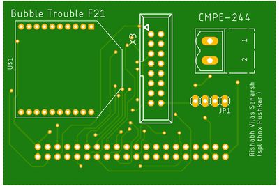
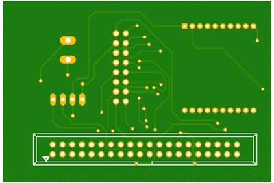
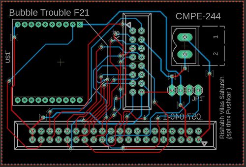
We chose Eagle AutoDesk as our PCB designing software since we got its free license for a year after registering with university email-id. The routing was done manually to create a PCB from a schematic. We designed one PCB, one for our game for our matrix controller. First, we created separate schematics for the controller that included all connections. We included the XBee mount available in the Adafruit library that enabled us an easy connection to the module. For MP3 we directly used male headers whose connection is mapped from the underside of the PCB. Once our schematics were done and we checked it several times. We would like to give a special mention to our roommate Pushkar who is quite familiar with Eagle AutoDesk. He helped us to cross-check the connection and provided us with tips to do better routing.PCB was sent to fabrication to JLCPCB China which provided PCB with an order of 5 and 2 layers of PCB and common grounded the rest of the copper area.
Elegoo Power Supply Module
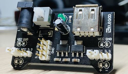
Rather than supplying power to the SJ-two board, led matrix, and MP3 decoder separately we decide to use the Power supply Module that came with the ELEGOO Upgraded Electronics Fun Kit. This supply module accepts input through a barrel jack from a battery, a 12V adapter, or any other source, and provides to our circuit a 5V as per our requirements. This module provides an inexpensive and convenient way to convert a 7-12V wall bug into 5V and 3.3V to power a solderless breadboard setup. The maximum output current is 700mA. One 5V connecter will go to the Vcc of the SJ-two board whereas 5V will be used to drive the 64x64 led matrix.
LED Matrix and Controller Board Enclosure
We designed our LED matrix enclosure and controller board enclosure from the boxes available to us. To give the player the maximum immersive experience we have placed our matrix at an angle. The player can sit back, relax and play the arcade game quite easily as the controller board is not connected to the matrix enclosure. The controller board has its own enclosure and the communication between the board takes place through the XBee module.
MP3 Decoder
This module is a kind of simple MP3 player device which is based on a high-quality MP3 audio chip---YX5300. It can support 8k Hz ~ 48k Hz sampling frequency MP3 and WAV file formats. There is a TF card socket on board, so you can plug the micro SD card that stores audio files. MCU can control the MP3 playback state by sending commands to the module via the UART port, such as switching songs, changing the volume, etc.
Hardware Design
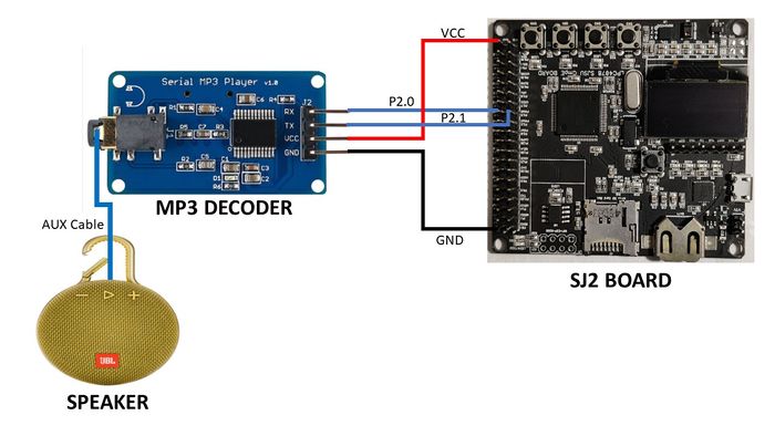
The MP3 decoder module uses 4 pins namely UART Tx, UART Rx, VCC, and GND. The module required 3.3V to power up which has been supplied from the SJ2 board. We have configured UART1 pins on the SJ2 board for sending commands to the decoder. The baud rate for this UART communication has been set to 9600 bps. This decoder also has a 3.5mm audio jack that has been connected to a speaker.
Software Design
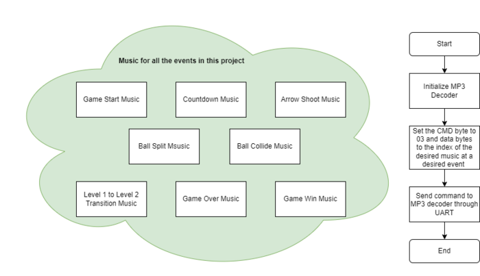
The command that we are using in our Bubble Trouble project is to play the music by accessing its index from the SD card. The function that sends this command is called play_music_at_index in our code. Before sending the command to play music at a certain index, we need to send the command [Select device] first. Serial MP3 Player only supports micro SD cards, so you should send “7E FF 06 09 00 00 02 EF” as described in the datasheet. Also, the commands are being sent using UART1 and the function uart__polled_put.
Controller Board and Main Board Communication
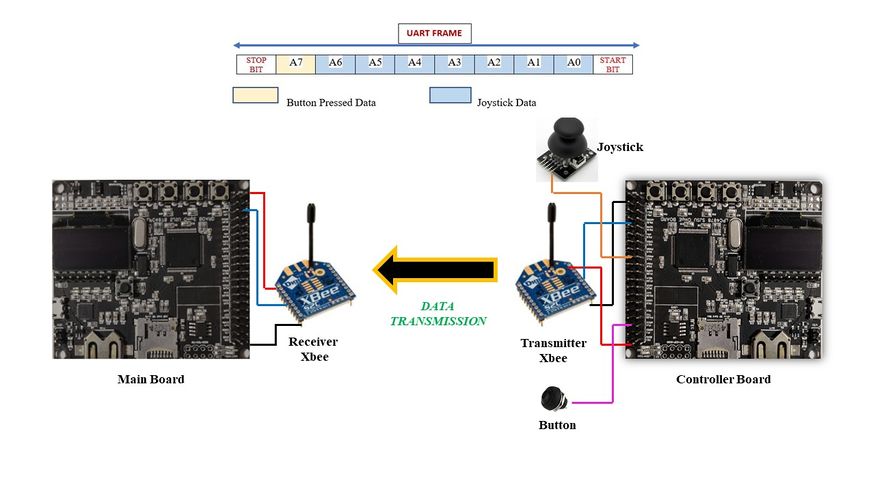
With an XBee Explorer connected between your computer and your XBee, and with the help of the X-CTU software, you can easily configure XBees, test connections, and pass data between your computer and remote XBees. X-CTU is free software, provided by Digi (the manufacturer of XBee), which we use to configure and manage XBees and test XBee networks. The SparkFun website linked, here, gives a perfect step-by-step guide to configuring the Xbees as transmitter and receiver. The controller board consists of the joystick, button press, and Xbee module. The character movement is controlled using a joystick whereas the button presses the shoot arrow. The joystick reading using is taken using ADC. Rather than reading a single value every time we have to enable burst mode on ADC that does repeated conversion at 400khz.This data is then sent from the controller board over to the mainboard (the one that has the game logic and led drivers) using Xbee. After the data is received at the receiver end it is sent over UART. The A0-A6 bits of the UART frame is the joystick ADC reading whereas the A7 bit of the frame is the button pressed data. If the button is not being pressed then blank data is sent. A UART interrupt is generated, which invokes an ISR which sends data into the queue. Now the task that is sleeping on the queue wakes up and depending on the data does the character movement.
Game Controller reading data from joystick and sending to UART logic
void read_joystick_and_send(void *p) {
  while (1) {
    uint16_t joystick_reading = adc__get_channel_reading_with_burst_mode(ADC__CHANNEL_2);
    joystick_reading = (joystick_reading * 125) / 4095;
    if (!(LPC_GPIO1->PIN & (1 << 31)))
      joystick_reading |= 1 << 7;
    uart_lab__polled_put(2, joystick_reading);
    vTaskDelay(5);
  }
}
Game Logic
Ball Trajectory
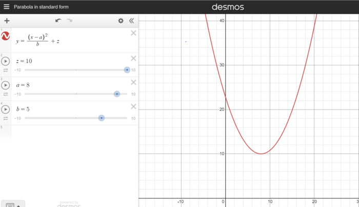
Bubble shooter uses an intelligent mechanism for the ball jumping. This makes user perceive the game ball jumping almost as real ball jumping and give them the best playing experience. In order to achieve that we have designed a ball jumping logic that follows a parabolic equation. The parabolic equation and graph are shown below:
As the game starts, we have set some initial ball coordinates from where the ball starts its trajectory. By using these staring coordinates of row and column, we then derive the parabolic path which this ball will follow. For deriving the equation, we have used 3 variables, which play the role of the start point slope, curvature and the height of the ball jump. These variables are defined as below:
Height Offset (z): As the name suggests, it is the distance between the maximum height our ball will jump and the upper wall. With ball size, its tendency to jump changes. So heavier ball jumps more as compared to light ball and we change height offset accordingly. Curvature (b): This decides the curvature of the trajectory. By increasing its value, the parabola keeps getting flat. We have given a constant value for this variable. Start (a): This value basically means which trajectory our ball will follow if given a start point coordinates, curvature and height offset. It is one of the most important variable as we update this variable, whenever we want to change the trajectory of the ball.
When ball is moving forward:
√((Row-Height Offset)*Curvature)+Column
When ball is moving backwards:
Column- √((Row-Height Offset)*Curvature)
Once the variables are defined, we now get the row coordinates by incrementing the column coordinates and feeding that to the derived parabolic equation which further updates the row coordinates.
Row = 〖(Column – Start)〗^2/Curvature+Height Offset
Now, this methodology was enough to make the ball seem a little close to the parabolic curve. However, on 64x64 LED matrix this did not seem to be an exact parabola and gives stairs like curvature. In order to solve this problem, we designed an algorithm to only display when there is a change in a row while columns keep incrementing. By doing this, our ball does not follow a ramp pattern and seems to be moving in a parabolic slope.
Important Equations:
int get_start_value(int row, int col, int height_offset) {
  return (sqrt((row - height_offset) * 5) + col);
}

int get_start_value_reverse(int row, int col, int height_offset) {
  if ((col - sqrt((row - height_offset) * 5)) > 0)
    return (col - sqrt((row - height_offset) * 5));
  else
    return (sqrt((row - height_offset) * 5) - col);
}

void parabolic_curve(int *row, int column, int start, int height_offset) {
  *row = (((column - start) * (column - start)) / 5) + height_offset;
}
One of the balls trajectory logic:
static void logic_ball_jumping1(void *p) {
  while (1) {
    int kill_this_task = 0;
    static int temp_col = 0;
    if (screen_transition && start_ball_2) {
      int temp_row;
      if (temp_col + ball[0].max_width >= 60) {
        ball[0].direction = 1;
      } else if (temp_col <= 3) {
        ball[0].direction = 0;
      }
      if (ball[0].direction)
        parabolic_curve(&temp_row, temp_col--, ball[0].start, ball[0].height_offset);
      else
        parabolic_curve(&temp_row, temp_col++, ball[0].start, ball[0].height_offset);
      if (temp_row != ball[0].row_pos) {
        display_ball(ball[0].row_pos, ball[0].col_pos, ball_size_1, BLACK);
        ball[0].row_pos = temp_row;
        ball[0].col_pos = temp_col;
        if (ball[0].row_pos >= ball[0].hit_ground) {
          if (need_to_update_height_offset && ball_size_1 == 3) {
            ball[0].height_offset = 20;
            ball[0].hit_ground = 50;
            need_to_update_height_offset = 0;
          } else if (need_to_update_height_offset && ball_size_1 == 2) {
            ball[0].height_offset = 30;
            ball[0].hit_ground = 54;
            need_to_update_height_offset = 0;
          }
          ball[0].start = get_start_value(ball[0].row_pos, ball[0].col_pos, ball[0].height_offset);
          if (ball[0].direction)
            ball[0].start = get_start_value_reverse(ball[0].row_pos, ball[0].col_pos, ball[0].height_offset);
        }
        display_ball(ball[0].row_pos, ball[0].col_pos, ball_size_1, ball[0].colour);
        vTaskDelay(100);
      }
    } else
      temp_col = 0;
  KILL_TASK:
    if (kill_this_task)
      vTaskSuspend(ball_1);
  }
}
Arrow Shooting and Ball Splitting
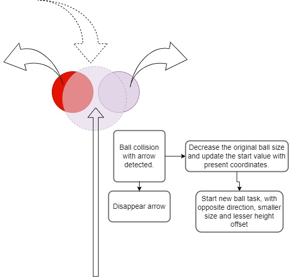
As discussed, when received MSB as high, it means the button is pressed and our character shoots an arrow thread in the air. This arrow splits the ball into two equal halves. Once the arrow coordinates match the ball coordinates, collision is detected and the ball is split into two halves. Below is how it is implemented.
Arrow and Ball collision logic as detected by Arrow:
int is_collision() {
  for (int j = 0; j < MAX_BALLS; j++) {
    for (int i = arrow.row_pos; i < character.row_pos; i++) {
      if ((ball[j].col_pos + ball[j].max_width == arrow.col_pos && ball[j].row_pos + ball[j].max_height >= i) ||
          (ball[j].col_pos == arrow.col_pos && ball[j].row_pos + ball[j].max_height >= i) ||
          (ball[j].col_pos < arrow.col_pos && (ball[j].col_pos + ball[j].max_width) > arrow.col_pos &&
           ball[j].row_pos + ball[j].max_height >= i)) {
        ball[j].is_collided = 1;
        arrow.is_collided = 1;
        game_score += 30;
        update_score_card();
        return 1;
      }
    }
  }
  return 0;
}
Arrow and Ball collision logic as detected by Ball:
if (ball[0].is_collided) {
  ball[0].is_collided = 0;
  display_ball(ball[0].row_pos, ball[0].col_pos, ball_size_1, BLACK);
  ball2_row = ball[1].row_pos;
  ball2_col = ball[1].col_pos;
  mp3_decoder__volume_set_level(30);
  mp3_decoder__play_song_at_index(06);
  if (ball_size_1 - 1 < 2) {
    ball_size_1 = 0;
    start_ball_2 = 0;
    reset_positions(&ball[0]);
    kill_this_task = 1;
    goto KILL_TASK;
  }
  split_ball(&ball_size_1, &ball[0].start, ball[0].row_pos, ball[0].col_pos, &ball[0].height_offset,
              ball[0].direction);
  ball[0].max_width -= 2;
  ball[0].max_height -= 2;
  temp_col = ball[0].col_pos;
  if (!level1_over)
    ball[0].hit_ground = 50;
  if (restart_game_screen == 0) {
    if (ball_size_1 == 3 && level1_over) {
      ball_2_init();
      ball_split_start_ball_2 = 1;
    } else if (ball_size_1 == 2 && level1_over) {
      ball_3_init();
      ball_split_start_ball_3 = 1;
    } else if (!level1_over) {
      ball_2_init();
      ball_split_start_ball_2 = 1;
    }
  }
}
The ball splitting function, which updates the parameters:
void split_ball(uint8_t *ball_size, uint8_t *start, int row, int col, uint8_t *height_offset, int direction) {
  take_backup();
  *height_offset = 10;
  need_to_update_height_offset = 1;
  if (direction)
    *start = get_start_value_reverse(row, col, *height_offset);
  else
    *start = get_start_value(row, col, *height_offset);
  *ball_size = *ball_size - 1;
  restore_backup();
}
Character Movement and Ways character can lose a life
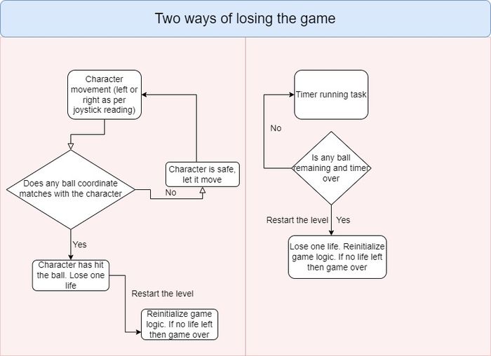
Character movement is detected using values read from a remote Joystick. This character can shoot an arrow but also can get out if one of the below scenarios occur:
Character movement and its collision with ball detection
void receive_joystick_data(void *p) {
  character.row_pos = 46;
  character.col_pos = 29;
  while (1) {
    if (screen_transition && !level2_over) {
      character.max_width = 9;
      char data = 0;
      if (uart_lab__get_char_from_queue(&data, portMAX_DELAY)) {
        if (data & (1 << 7)) {
          pressed = 1;
        }
        data &= 127;
        move_character(data);
        for (int j = 0; j < MAX_BALLS; j++) {
          if ((((ball[j].col_pos > character.col_pos) && (ball[j].col_pos < character.col_pos + character.max_width)) ||
               ((ball[j].col_pos + ball[j].max_width > character.col_pos + 1) &&
                (ball[j].col_pos + ball[j].max_width < character.col_pos + character.max_width))) &&
              (character.row_pos <= ball[j].row_pos + ball[j].max_height)) {
            counter_flag = 1;
            mp3_decoder__volume_set_level(30);
            mp3_decoder__play_song_at_index(04);
            score_board_data.no_of_lives_left--;
            restart_game_screen = 1;
            screen_transition = 0;
          }
        }
      }
    }
  }
}
Timer logic. If timer gets over, character looses a life.
void game_counter(void *p) {
  static row = 62;
  int delay = 500;

  while (1) {
    if (screen_transition) {
      for (uint8_t i = 0; i <= game_counter_column; i++) {
        led_matrix__set_pixel(row, i, PURPLE);
        led_matrix__set_pixel(row + 1, i, PURPLE);
      }
      vTaskDelay(delay);
      if (counter_flag == 0) {
        for (uint8_t i = 0; i <= game_counter_column; i++) {
          led_matrix__set_pixel(row, i, BLACK);
          led_matrix__set_pixel(row + 1, i, BLACK);
        }
        if (!counter_flag)
          game_counter_column--;
      }
      if (game_counter_column == 0 && (ball_size_1 || ball_size_2)) {
        score_board_data.no_of_lives_left--;
        restart_game_screen = 1;
        screen_transition = 0;
      }
    }
  }
}
Scoring
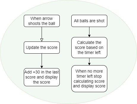
Scoring in the game is based on two factors. One, when the arrow shoots the ball and another is based on the timer left when the level is passed. Below is the game logic:
Updating the score logic:
void update_score_card() {
    int i = 0;
    int temp = game_score;
    for (int j = 23; j < 38; j++) {
      for (int k = 0; k <= 6; k++) {
        led_matrix__set_pixel(k, j, BLACK);
      }
    }
    while (temp) {
      led_matrix_basic_graphics__display_number(0, 33 - i, temp % 10, PURPLE);
      temp = temp / 10;
      i += 5;
    }
}
Game Tasks
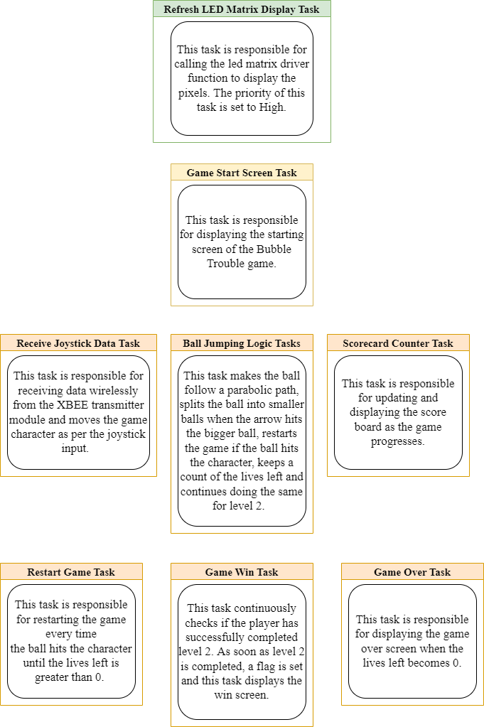
The figure below shows the FreeRTOS tasks that have been used in the Bubble Trouble game.
Testing,Technical Challenges and learning
1) We encountered an issue during the initial phase of the project where the 33rd row of the LED matrix was being displayed on the first row. This issue was happening because we were not resetting the Output Enable pin of the LED Matrix before clocking in the next row of data. We were able to resolve this issue after thoroughly reading the Sparkfun article on RGB Matrix Panels.
2) The main game logic of our game revolves around the concept of how balls bounce in the game. We could have developed a linear ball-bouncing logic. However, in order to make the ball bounce more realistic, we decided to resort to developing a parabolic ball jumping logic. This might sound easy at first, but, it was quite difficult to develop the logic. We had to take into consideration three cases viz. ball start logic, ball hitting the ground and bounce logic, and ball bouncing the “wall” that is the side of the back after hitting the screen. This challenge was time-consuming as it required us to carry out multiple permutations and combinations of values w.r.t the rows and columns of the led matrix and then display it on the screen. We did multiple iterations until we reached a smooth jumping pattern. Another challenge was to start two different parabolic functions after the arrow hit the ball. It was quite enjoying task as it refreshed our undergraduate mathematics geometry and algorithm thinking.
3) Real Use of Volatile keyword: In level 2 there are multiple-sized balls. When the character gets hit by a smaller after the ball, our objective was to restart level 2 with the biggest ball size. However, we were facing the issue that level 2 restart was starting with smaller balls. Our first guess was that it was happening due to some race conditions as there were multiple “ball_jumping” tasks running. But after debugging the code, the global “ball_size” variables were not getting reinitialized. This was happening because the compiler was optimizing the code and not reloading them from the memory. In order to solve it, we declared these variables as volatile.
Conclusion
This project was a great success and learning experience. We were able to replicate our original game idea and successfully integrate every module used for the project. The LED matrix was able to load our character moving, ball jumping and ball splitting all while playing the sounds for each of the game items. At the time of the demo, we also displayed our counter decrementing and score incrementing logic. We had various obstacles during the project, including trouble getting the LED matrix driver up and running, finding out how to integrate collision detection with so many game objects, designing and maintaining our sophisticated game logic state machine, and much more. During the course of our project, we were able to comprehend the practical application of FreeRTOS. We realized that setting targets for each week and achieving them, can help compartmentalize the project to eventually reach the final expectation. This project upped our level of Embedded Software and strengthened our grip on the same.
Acknowledgement
We would like to express our gratitude towards Professor Preetpal Kang for sharing valuable inputs and knowledge throughout the duration of the project. We would also like to thank our ISA Ellis Makwana for guiding us as and when required.
Appendix
Project Video
Project Source Code
Bubble Trouble Git Lab Source Code Link
