Difference between revisions of "S21: (RC)^2"
Proj user10 (talk | contribs) (→Mobile Application) |
Proj user10 (talk | contribs) (→Technical Challenges) |
||
| (27 intermediate revisions by the same user not shown) | |||
| Line 1: | Line 1: | ||
| − | |||
== '''(RC)<sup>2</sup>''' == | == '''(RC)<sup>2</sup>''' == | ||
| − | + | [[File:RCRC_RCRC.jpeg|600px|center|]] | |
| − | + | ||
<HR> | <HR> | ||
| Line 9: | Line 8: | ||
== Abstract == | == Abstract == | ||
| − | + | We are team (RC)², also known as (Really.Cool).R.C. Our mission is to build an RC car utilizing SJ2 Boards communicating through CAN bus. Our RC car is capable of navigating to a destination controlled by an Android application while avoiding obstacles that may be in its path. The RC car is composed of various nodes that each have a specific task such as reading sensor data, controlling the motor, and attaining compass values. We also provide the user with an Android application to provide the car with each destinations and start/stop the car on command | |
| − | |||
=== Introduction === | === Introduction === | ||
| Line 22: | Line 20: | ||
=== Team Members & Responsibilities === | === Team Members & Responsibilities === | ||
| − | |||
Gitlab Project Link - https://gitlab.com/rc-2/sjtwo-c | Gitlab Project Link - https://gitlab.com/rc-2/sjtwo-c | ||
| Line 231: | Line 228: | ||
== Parts List & Cost == | == Parts List & Cost == | ||
| − | |||
{| class="wikitable" | {| class="wikitable" | ||
|- | |- | ||
| Line 242: | Line 238: | ||
! scope="row"| 1 | ! scope="row"| 1 | ||
| RC Car | | RC Car | ||
| − | | | + | | DEERC |
| 1 | | 1 | ||
| $129.99 | | $129.99 | ||
| Line 305: | Line 301: | ||
| 1 | | 1 | ||
| $5.90 | | $5.90 | ||
| + | |- | ||
| + | ! scope="row"| 12 | ||
| + | | External 12V Battery | ||
| + | | Ovonic [https://www.amazon.com/gp/product/B07CVBSRTZ/ref=ppx_yo_dt_b_asin_title_o02_s00?ie=UTF8&psc=1] | ||
| + | | 1 | ||
| + | | $59.99 | ||
| + | |- | ||
| + | ! scope="row"| 13 | ||
| + | | Standoffs | ||
| + | | Geekworm [https://www.amazon.com/Geekworm-Raspberry-Installation-Standoff-Accessories/dp/B0756CW6Y2/ref=sr_1_1?dchild=1&keywords=standoffs&qid=1622265787&s=electronics&sr=1-1] | ||
| + | | 1 | ||
| + | | $10.89 | ||
| + | |- | ||
|} | |} | ||
| + | |||
<HR> | <HR> | ||
<BR/> | <BR/> | ||
| − | == Printed Circuit Board | + | == Printed Circuit Board & Connection== |
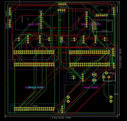
| − | + | The PCB is designed to have 4 Board connected to it. However, in our last configuration we separate the Bridge Node and the Sensor Node and we used a protoboard to connect the Bridge Node onto the car. | |
<br> | <br> | ||
[[File:pcb_design_rcrc_1.jpeg|493px]] | [[File:pcb_design_rcrc_1.jpeg|493px]] | ||
| Line 317: | Line 327: | ||
[[File:pcb_design_rcrc_3.jpeg|495px]] | [[File:pcb_design_rcrc_3.jpeg|495px]] | ||
[[File:pcb_design_rcrc_4.jpeg|500px]] | [[File:pcb_design_rcrc_4.jpeg|500px]] | ||
| + | |||
| + | Here is how each ECU is connected to there respective parts. | ||
| + | |||
| + | [[File:Circuitry_RCRC.JPG|800px|align|center|thumb|Wiring Diagram]] | ||
| + | |||
<HR> | <HR> | ||
<BR/> | <BR/> | ||
| Line 334: | Line 349: | ||
* Driver: stop the car when missing the Sensor information when the frame is missing for more than 500ms | * Driver: stop the car when missing the Sensor information when the frame is missing for more than 500ms | ||
* Motor: straighten the car out and stop the car | * Motor: straighten the car out and stop the car | ||
| − | |||
| Line 639: | Line 653: | ||
*;'Void geo__process_gps_data(void)’: The main function used in 10Hz callback to consistently read gps, magnetometer, and accelerometer data. It then calculates heading angle and bearing angle before sending all raw data and angles onto the CAN bus. | *;'Void geo__process_gps_data(void)’: The main function used in 10Hz callback to consistently read gps, magnetometer, and accelerometer data. It then calculates heading angle and bearing angle before sending all raw data and angles onto the CAN bus. | ||
| − | + | *;'Void geo__transformation_mag(float uncalibrated_acc_values[3])': Geo__transformation functions are used to apply calibration and bias values o sensor data. The hard-coded calibration and bias values are from Magmaster or Magneto calibration programs | |
'''2.''' The ''gps module'' provides basic functions to setup and interface with the Adafruit Ultimate GPS module.: | '''2.''' The ''gps module'' provides basic functions to setup and interface with the Adafruit Ultimate GPS module.: | ||
| Line 657: | Line 671: | ||
=== Technical Challenges === | === Technical Challenges === | ||
| − | ''' | + | *'''Inconsistent Heading''': |
:The heading issue turned out to be related to the PCB integration. When testing the compass separately connecting by only dupont cables it performed as expected. This raises the importance of “unit testing” components, before integration to more easily locate issues in integration. | :The heading issue turned out to be related to the PCB integration. When testing the compass separately connecting by only dupont cables it performed as expected. This raises the importance of “unit testing” components, before integration to more easily locate issues in integration. | ||
| − | ''' | + | *'''Compass Calibration''': |
:For our compass calibration we ended up implementing all the algorithms we could find. The two most prominent methods are the “simple” two-point style calibration and the magmaster / magneto ardruino method. The magmaster method was the more extensive of the two and not extremely complicated when utilizing the Arduino program developed by YuriMat. Prior to being able to use this software, getting a hand-held magnetic compass is crucial. These are extremely more useful than any compass application on the Android of Apple store. A hand-held compass allowed us to locate a spot with little to no interference, making it a good location to preform calibration. | :For our compass calibration we ended up implementing all the algorithms we could find. The two most prominent methods are the “simple” two-point style calibration and the magmaster / magneto ardruino method. The magmaster method was the more extensive of the two and not extremely complicated when utilizing the Arduino program developed by YuriMat. Prior to being able to use this software, getting a hand-held magnetic compass is crucial. These are extremely more useful than any compass application on the Android of Apple store. A hand-held compass allowed us to locate a spot with little to no interference, making it a good location to preform calibration. | ||
| Line 733: | Line 747: | ||
The Driver Node receive and decode these 4 CAN frame: | The Driver Node receive and decode these 4 CAN frame: | ||
| − | + | * SONAR_VALUES: Ultrasonic sensor values from the Sensor Node. | |
| − | + | * COMPASS_HEADING_DISTANCE: Geo-location information(Heading angle, Bearing angle, and Distance to destination) from the GEO Node. | |
| − | + | * GPS_DESTINATION_REACHED: A bit to signify if it has reached its destination from the GEO Node. | |
| − | + | * DRIVE_START: Used to Start or Stop sending the Motor frame to the Motor Node, this frame is received from the Bridge Node. | |
At the top level, the ''periodic_callbacks.c'' only calls 3 functions in the 10hz periodic callback: | At the top level, the ''periodic_callbacks.c'' only calls 3 functions in the 10hz periodic callback: | ||
| − | + | *'''''(void)can_bus_message_handler__receive()''''': Receive and decode CAN dataframe from the Sensor Node, GEO Node, and the Bridge Node. Then generate the Motor command based on those frames. | |
| − | + | *'''''(void)can_bus_message_handler__transmit()''''': Transmit the Motor command onto the CAN bus. | |
| − | + | *'''''(void)can_handler__manage_mia_10hz()''''': Check if any dataframe is missing and handle it via the MIA handlers | |
The main part of the Driver Node is how it can generate the appropriate Motor Command given all the data from the other 3 nodes. The workflow(Represented by the above diagram) can be understood as: | The main part of the Driver Node is how it can generate the appropriate Motor Command given all the data from the other 3 nodes. The workflow(Represented by the above diagram) can be understood as: | ||
| − | + | * Check if there is any obstacle based on the Sensor values | |
| − | + | * If there is an obstacle, update the steering value to avoid the obstacle | |
| − | + | * If not, update the steering to head to destination based on the Geo Node frame | |
| − | + | * Set the speed of the car | |
In our final version of (RC)², there are a few flags that are used to set the speed: | In our final version of (RC)², there are a few flags that are used to set the speed: | ||
| − | + | * ''start_driving'' flag: This flag is set/clear by the Start/Stop signal or the Destination_reached signal: It will set the car speed to 0 | |
| − | + | * ''steering_to_destination'': If this flag is set, the car is currently steering to the destination, and the speed is set at our medium default speed (when steer you should slow down) | |
| − | + | * ''very_close_to_destination'': This flag is set based on the Distance left to the destination received from the GEO node. If this flag is set, the speed will also be set to the medium default speed so that it will not overshoot the destination. | |
| − | + | * Else, the car speed is set to the default speed to drive to the destination. | |
=== Technical Challenges === | === Technical Challenges === | ||
| Line 785: | Line 799: | ||
== Mobile Application == | == Mobile Application == | ||
| − | + | https://gitlab.com/rc-2/rc_car2_android_app | |
=== Software Design === | === Software Design === | ||
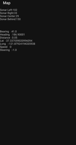
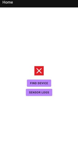
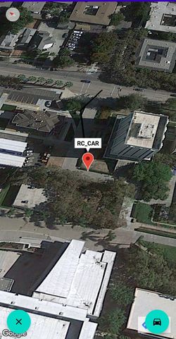
We initially wanted to create an iOS application because the majority of the group had iPhones, but we created an android application instead using Android Developer Studio as no one had a Mac for iOS development. Below are images of the different screens in our application. | We initially wanted to create an iOS application because the majority of the group had iPhones, but we created an android application instead using Android Developer Studio as no one had a Mac for iOS development. Below are images of the different screens in our application. | ||
| − | |||
| − | + | [[File:CarScreen.jpeg|250px|middle|left|thumb|Image of the sensor screen of the app]] | |
| + | |||
| + | |||
| + | [[File:DataScreen.jpeg|250px|middle|center|thumb|Image of the data screen of the app]] | ||
| + | |||
| + | |||
| + | [[File:HomeScreen.jpeg|250px|middle|left|thumb|Image of the home screen of the app]] | ||
| + | |||
| + | |||
| + | [[File:GoogleMapsScreen.jpeg|250px|middle|center|thumb|Iimage of the google maps screen of the app]] | ||
| + | |||
| + | |||
| + | |||
| − | + | === Technical Challenges === | |
| − | + | *'''Interfacing ESP8266 & Smart Phone - MQTT Protocol''' | |
| + | :The process of implementing the MQTT protocol was not straight foward. Connecting to the MQTT server via ESP8266 was also difficult since everytime the wifi access point changed it would need to be reflashed with a new IP address. Keeping a static mobile hotspot to allow the ESP8266 to connect solved us having to reflash. To solve the MQTT connection problem, we set up the MQTT server using a docker on google cloud, which worked for communication to the MQTT server. | ||
| + | *'''Flashing ESP8266''' | ||
| + | :Flashing the ESP8266 with custom software to handle MQTT was a complicated process. Using a straight connection to the ESP8266 through GPIO we were unable to flash the module without failing. Buying a 3rd party breakout board with an Arduino UNO allowed us to easily flash the ESP8266 on the first try. | ||
| + | |||
| + | *'''Random Crashes''' | ||
| + | :Diagnosing android app crashes is a little more difficult than the standard SJ2 development typically done in class. When reasons for crash are not as obvious a useful debug tool, Android Vitals, will allow you to view stack traces leading up to a crash. These tools are valuable when debugging seemingly random crashes during application usage. | ||
| − | |||
| − | |||
<HR> | <HR> | ||
<BR/> | <BR/> | ||
| Line 821: | Line 850: | ||
=== Project Video === | === Project Video === | ||
| − | * YouTube Video Link: <font color="fire"><U>[https://www.youtube.com/watch?v= | + | * YouTube Video Link: <font color="fire"><U>[https://www.youtube.com/watch?v=Ew_gBAFJteU Initial RC² Run ]</U></font> |
=== Project Source Code === | === Project Source Code === | ||
| Line 831: | Line 860: | ||
* Work with an '''Electronic Speed Controller(ESC) that is not resined''' into the car's platform! When the RC² team took apart the car, we realized that the ESC has been completely resined into the car's platform. This restrained us from directly controlling the ESC and forced us to control the ESC through the transmit controller. This made the car jerky when adjusting its speed. If your RC Car's ESC is resined into the platform, we suggest completely removing the ESC and purchasing a new one to integrate with your RC car. | * Work with an '''Electronic Speed Controller(ESC) that is not resined''' into the car's platform! When the RC² team took apart the car, we realized that the ESC has been completely resined into the car's platform. This restrained us from directly controlling the ESC and forced us to control the ESC through the transmit controller. This made the car jerky when adjusting its speed. If your RC Car's ESC is resined into the platform, we suggest completely removing the ESC and purchasing a new one to integrate with your RC car. | ||
| + | |||
| + | * Please starts early with the PCB design so that you can have a solid hardware. By doing this, you will have more time playing with the threshold that can affected the driving experience tremendously | ||
| + | |||
| + | * Choose quality components! Treat yourself as an engineer that is paid $100/hour so don't waste your time on cheap, unreliable parts. | ||
| + | |||
| + | * Buy Extra components! Incase one of them fail to calibrate, gives out bad values on the demo day. | ||
| + | |||
| + | * Make sure that your power source is stable. The GPS and Compass module is extremely sensitive so if your power source is unstable, it can negatively affect your data. | ||
| + | |||
| + | * We found this out at the very end of the class when testing our car. It is good to have a physical compass. Using your phone as the compass can affect the compass if it is close to the car. | ||
=== Acknowledgement === | === Acknowledgement === | ||
Latest revision as of 05:34, 29 May 2021
Contents
(RC)2
Abstract
We are team (RC)², also known as (Really.Cool).R.C. Our mission is to build an RC car utilizing SJ2 Boards communicating through CAN bus. Our RC car is capable of navigating to a destination controlled by an Android application while avoiding obstacles that may be in its path. The RC car is composed of various nodes that each have a specific task such as reading sensor data, controlling the motor, and attaining compass values. We also provide the user with an Android application to provide the car with each destinations and start/stop the car on command
Introduction
The project was divided into five main components that were important to the RC car as a whole:
- Sensor Node
- Motor Node
- Geographic Controller
- Communication Bridge/OLED
- Driver Node
Team Members & Responsibilities
Gitlab Project Link - https://gitlab.com/rc-2/sjtwo-c
Jesse Pham
Huy Nguyen
Brian Tran
Prabjyot Obhi
Arun Hiremath
Michael Wang
- Sensor
- Huy - https://gitlab.com/vyhuy2004
- Prabjyot - https://gitlab.com/PrabjyotObhi
- Driver
- Motor
- Jesse - https://gitlab.com/JessePhams
- Michael - https://gitlab.com/mwmichaelwang
- Geographical
- Brian - https://gitlab.com/Brian1234132
- Arun - https://gitlab.com/arunhiremath92
- Communication Bridge Controller & LCD
- Prabjyot - https://gitlab.com/PrabjyotObhi
- Arun - https://gitlab.com/arunhiremath92
Schedule
| Week# | Start Date | End Date | Task | Status |
|---|---|---|---|---|
| 1 | 03/01/2021 | 03/07/2021 |
|
Complete |
| 2 | 03/08/2021 | 03/14/2021 |
|
Complete |
| 3 | 03/15/2021 | 03/21/2021 |
|
Complete |
| 4 | 03/22/2021 | 03/28/2021 |
|
Complete |
| 5 | 03/29/2021 | 04/04/2021 |
|
Complete |
| 6 | 04/05/2021 | 04/11/2021 |
|
Complete |
| 7 | 04/12/2021 | 04/18/2021 |
|
Complete |
| 8 | 04/19/2021 | 04/25/2021 |
|
Complete |
| 9 | 04/26/2021 | 05/02/2021 |
|
Complete |
| 10 | 05/03/2021 | 05/09/2021 |
|
Complete |
| 11 | 05/10/2021 | 05/16/2021 |
|
Complete |
| 12 | 05/17/2021 | 05/23/2021 |
|
Complete |
| 13 | 05/24/2021 | 05/26/2021 |
|
Complete |
Parts List & Cost
| Item# | Part Desciption | Vendor | Qty | Cost |
|---|---|---|---|---|
| 1 | RC Car | DEERC | 1 | $129.99 |
| 2 | CAN Transceivers MCP2551-I/P | Microchip [2] | 8 | Free Samples |
| 3 | GPS Module | Adafruit [3] | 1 | $59.99 |
| 4 | Compass | Adafruit [4] | 1 | $14.95 |
| 5 | ESP8266 (WiFi) | DIYmall [5] | 1 | $14.95 |
| 6 | HC-020K (Wheel Encoder) | Hilitchi [6] | 1 | $8.99 |
| 7 | URM09 Ultrasonic Sensor (I²C) | DFRobot [7] | 4 | $12.90 |
| 8 | SJ2 Board Microcontroller | SCE [8] | 5 | $250.00 |
| 9 | Male/Female Headers | DEPEPE [9] | 1 | $5.00 |
| 10 | Screw Terminal Block Connectors | DZGGI [10] | 1 | $7.99 |
| 11 | CR1220 Lithium Battery | Energizer [11] | 1 | $5.90 |
| 12 | External 12V Battery | Ovonic [12] | 1 | $59.99 |
| 13 | Standoffs | Geekworm [13] | 1 | $10.89 |
Printed Circuit Board & Connection
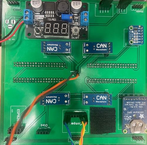
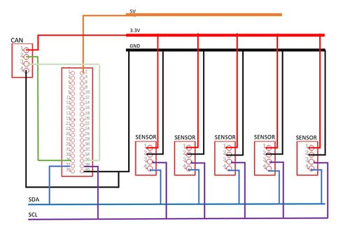
The PCB is designed to have 4 Board connected to it. However, in our last configuration we separate the Bridge Node and the Sensor Node and we used a protoboard to connect the Bridge Node onto the car.
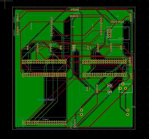
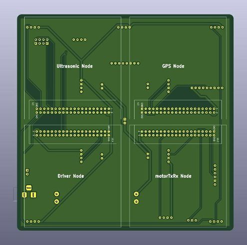
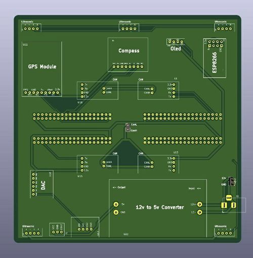
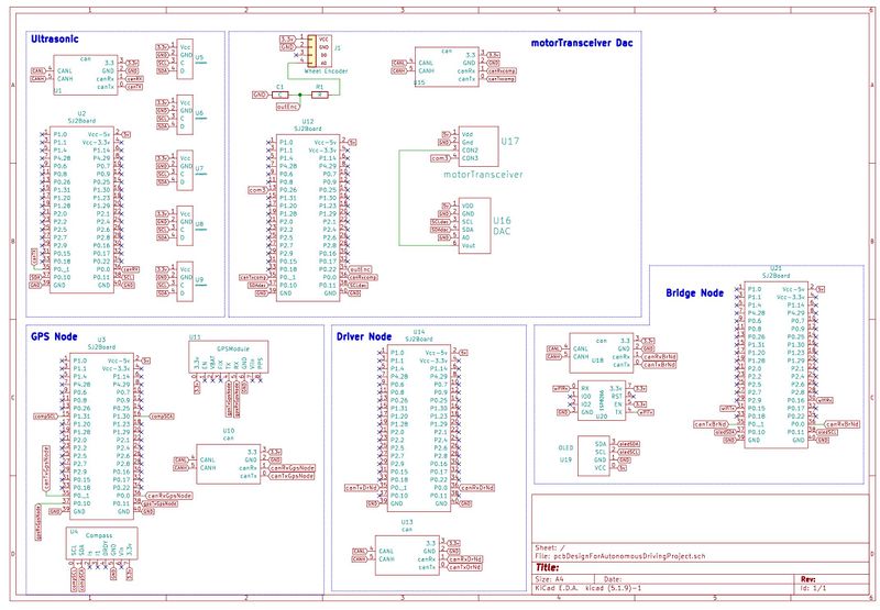
Here is how each ECU is connected to there respective parts.
CAN Communication
Priority Logic:
- Our two highest priority signals are DRIVE_STOP and DRIVE_START, and we prioritized stopping the car over starting the car as a matter of safety.
- GPS_DESTINATION_LOCATION is the next highest signal because we would need to have a valid location to be able to properly navigate the car.
- SONAR_VALUES has a priority right below GPS_DESTINATION_LOCATION because once the destination is set, the car would need to read sensor data to avoid potential obstacles.
- COMPASS_HEADING_DISTANCE would be the signal with a priority below the SONAR_VALUES signal as the car would need a proper heading in order to navigate to a destination.
- MOTOR_VALUE is the signal sending from Driver Node to the Motor Node to actuate the car
- The signals with the lowest priority are those that we used in our debugging process over Busmaster.
Missing-In-Action Management:
- Driver: stop the car when missing the Sensor information when the frame is missing for more than 500ms
- Motor: straighten the car out and stop the car
Hardware Design
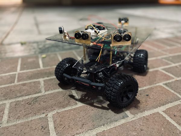
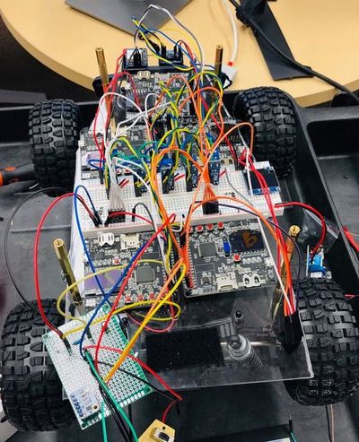
Our initial CAN bus was based on a breadboard that contained a lot of jumper/dupont wires. This design was sufficient for testing purposes as we worked to meet the in-class checkpoints; however, as we developed our RC car, we realized that a handful of connections were troublesome to the development of the car. As opposed to continuously rewiring and checking connections, we decided to invest time into PCB design to minimize connections and fix hardware issues. Below is a before and after comparison of our RC Car.
DBC File
VERSION ""

NS_ :
	BA_
	BA_DEF_
	BA_DEF_DEF_
	BA_DEF_DEF_REL_
	BA_DEF_REL_
	BA_DEF_SGTYPE_
	BA_REL_
	BA_SGTYPE_
	BO_TX_BU_
	BU_BO_REL_
	BU_EV_REL_
	BU_SG_REL_
	CAT_
	CAT_DEF_
	CM_
	ENVVAR_DATA_
	EV_DATA_
	FILTER
	NS_DESC_
	SGTYPE_
	SGTYPE_VAL_
	SG_MUL_VAL_
	SIGTYPE_VALTYPE_
	SIG_GROUP_
	SIG_TYPE_REF_
	SIG_VALTYPE_
	VAL_
	VAL_TABLE_

BS_:

BU_: DBG DRIVER IO MOTOR SENSOR GEO BRIDGE


BO_ 101 DRIVE_STOP: 1 BRIDGE
 SG_ DRIVE_STOP : 0|8@1+ (1,0) [0|0] "" DRIVER

BO_ 102 DRIVE_START: 1 BRIDGE
 SG_ DRIVE_START : 0|8@1+ (1,0) [0|0] "" DRIVER

BO_ 121 GPS_DESTINATION_LOCATION: 8 BRIDGE
 SG_ DEST_LATITUDE : 0|28@1+ (0.000001,-90.000000) [-90|90] "deg" GEO
 SG_ DEST_LONGITUDE : 28|29@1+ (0.000001,-180.000000) [-180|180] "deg" GEO

BO_ 131 SONAR_VALUES: 8 SENSOR
 SG_ SONAR_VALUES_left : 0|8@1+ (1,0) [0|150] "cm" DRIVER
 SG_ SONAR_VALUES_right : 8|8@1+ (1,0) [0|150] "cm" DRIVER
 SG_ SONAR_VALUES_front : 16|8@1+ (1,0) [0|150] "cm" DRIVER
 SG_ SONAR_VALUES_back : 24|8@1+ (1,0) [0|150] "cm" DRIVER

BO_ 141 COMPASS_HEADING_DISTANCE: 8 GEO
  SG_ HEADING : 0|12@1+ (0.1,0) [0|359.9] "deg" DRIVER,BRIDGE
  SG_ BEARING : 12|12@1+ (0.1,0) [0|359.9] "deg" DRIVER,BRIDGE
  SG_ DISTANCE : 24|17@1+ (0.01,0) [0|0] "m" DRIVER,BRIDGE

BO_ 151 MOTOR_VALUES: 3 DRIVER
 SG_ MOTOR_VALUES_speed : 0|8@1+ (1,-25) [-25|25] "kph" MOTOR
 SG_ MOTOR_VALUES_steering : 8|6@1+ (0.1,-2.1) [-2.1|2.1] "deg" MOTOR

BO_ 161 MOTOR_VALUES_TO_DRIVER: 3 MOTOR
 SG_ MOTOR_VALUES_TO_DRIVER_speed : 0|8@1+ (1,-25) [-25|25] "kph" DRIVER

BO_ 171 GPS_DESTINATION_REACHED: 1 GEO
 SG_ DESTINATION_REACHED : 0|1@1+ (1,0) [0|1] "bool" DRIVER,BRIDGE

BO_ 181 GPS_RAW_DATA: 8 GEO
 SG_ CURR_LATITUDE : 0|28@1+ (0.000001,-90.000000) [-90|90] "deg" BRIDGE
 SG_ CURR_LONGITUDE : 28|29@1+ (0.000001,-180.000000) [-180|180] "deg" BRIDGE
 SG_ GPS_QUALITY : 57|2@1+ (1,0) [0|2] "val" BRIDGE

BO_ 182 COMPASS_ACCEL_RAW_DATA: 6 GEO
 SG_ ACCEL_X : 0|16@1+ (0.01,-162.01) [-162.01|162.01] "ms^2" BRIDGE
 SG_ ACCEL_Y : 16|16@1+ (0.01,-162.01) [-162.01|162.01] "ms^2" BRIDGE
 SG_ ACCEL_Z : 32|16@1+ (0.01,-162.01) [-162.01|162.01] "ms^2" BRIDGE

BO_ 183 COMPASS_MAG_RAW_DATA: 6 GEO
 SG_ MAG_X : 0|16@1+ (0.01,-162.01) [-162.01|162.01] "mT" BRIDGE
 SG_ MAG_Y : 16|16@1+ (0.01,-162.01) [-162.01|162.01] "mT" BRIDGE
 SG_ MAG_Z : 32|16@1+ (0.01,-162.01) [-162.01|162.01] "mT" BRIDGE

BO_ 191 DRIVER_HEARTBEAT: 1 DRIVER
 SG_ DRIVER_HEARTBEAT_cmd : 0|8@1+ (1,0) [0|0] "" SENSOR, MOTOR, GEO

CM_ BU_ DRIVER "The driver controller driving the car";
CM_ BU_ MOTOR "The motor controller of the car";
CM_ BU_ SENSOR "The sensor controller of the car";
CM_ BO_ 191 "Sync message used to synchronize the controllers";
CM_ SG_ 191 DRIVER_HEARTBEAT_cmd "Heartbeat command from the driver";

BA_DEF_ "BusType" STRING ;
BA_DEF_ BO_ "GenMsgCycleTime" INT 0 0;
BA_DEF_ SG_ "FieldType" STRING ;

BA_DEF_DEF_ "BusType" "CAN";
BA_DEF_DEF_ "FieldType" "";
BA_DEF_DEF_ "GenMsgCycleTime" 0;

BA_ "GenMsgCycleTime" BO_ 100 1000;
BA_ "GenMsgCycleTime" BO_ 200 50;
BA_ "FieldType" SG_ 100 DRIVER_HEARTBEAT_cmd "DRIVER_HEARTBEAT_cmd";

VAL_ 100 DRIVER_HEARTBEAT_cmd 2 "DRIVER_HEARTBEAT_cmd_REBOOT" 1 "DRIVER_HEARTBEAT_cmd_SYNC" 0 "DRIVER_HEARTBEAT_cmd_NOOP" ;
Sensor ECU
The sensor node is responsible for gathering information from the 4 surrounding sensors. Our team decided to keep the sensor node by itself as avoiding obstacles is more critical than other tasks in our design. Thus, keeping an ECU free of any other task and only responsible for gathering sensor data and push it onto the CAN bus is our solution for a worry-free sensor reading
Hardware Design
1. CAN Transceiver
- This module will be used to communicate with the Driver Node to send data sensor values through CAN communication protocol. The CAN transceiver will be powered by a +3.3V source with its Transmit Line (Tx) connected to GPIO Pin P0.1 and its Receive Line (Rx) connected to GPIO Pin P0.0.
2. Ultrasonic Sensor
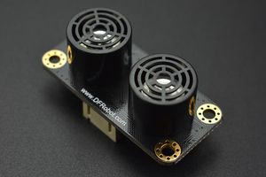
- Getting the right distance requires some research on each team depends on your project requirement. Our team settle for a no-frill Ultrasonic Sensor from DFRobots due to its easy implementation and its cost-effective. As Preet always mentioned in class: Think like an engineering being paid $100/hour, don't waste your time on cheap part that can take you way too long to implement. This sensor from DFRobots have different communication protocol that your team can choose based on your own experience. We want to focus on other node so we decided to choose the I2C package that makes configuring and reading value sensor from this node simple.
Software Design
The Sensor Node consists of 3 main modules: can_bus_message_handler, ultrasonic_system, and ultrasonic_sensor
1. The ultrasonic_sensor module This module is written to provide the user with access to our sensor. I simplified the driver to provide users with only 3 main functions:
- 'void ultrasonic_sensor__init_i2c_port(i2c_e i2c_number)'
- Initialize the i2c port that is used for the sensors
- 'void ultrasonic_sensor__enable_burst_mode(i2c_e i2c_number, uint8_t sensor_address)'
- Enable burst measuring mode for our sensor
- 'uint8_t ultrasonic_sensor__get_value(i2c_e i2c_number, uint8_t sensor_address)'
- Get the sensor reading provides the sensor address
2. The ultrasonic_system module This module is built on top of the ultrasonic_sensor module above so that it can be implemented with the whole system. It provides the user with 2 main functions:
- 'void ultrasonic_system__init(void)'
- This function is responsible for initiating the 4 ultrasonic sensors with their addresses and configure the i2c communication
- 'dbc_SONAR_VALUES_s ultrasonic_system__get_all_values(void)'
- This function is responsible for getting all the ultrasonic sensors, storing them in a local sensor struct created by the auto-generated code from the DBC file, and return that struct back to the user
3. The can_bus_message_handler module This module is designed to be simple. Thus, the only function needs in this case is:
- 'bool can_bus_message_handler__transmit_sensor(void)'
- This function is responsible for calling the ultrasonic_system__get_all_values as discussed above and send the data over the CAN bus
Technical Challenges
- Bad ultrasonic sensor
- Although there are several economical ultrasonic sensors out there, we think it is not worth the time debugging an ultrasonic sensor that may fail at any given time. Our initial ultrasonic sensor gives us decent readings but it occasionally fails to read the distance. We did some research on other sensors and found the one from DFRobots which is easy to implement and provide a decent reading with our range of application.
- Integration with Bridge node
- When we order our PCB, we decided to combine the Bridge node and the Ultrasonic node together. However, our test shows that the structure of our programs is not in sync, which made the ultrasonic sensor froze for some time during its operation. We decided to separate the two nodes. Should the 2 nodes are developed with the same structures at the beginning, we could potentially get it working. Nonetheless, these Nodes are designed differently hence integrating it requires a complete rewrite of the nodes which we decided not to pursue
Motor ECU
Hardware Design
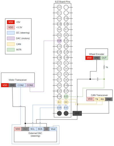
The hardware design for the motor node requires four main components to be connected to the SJ2 Board:
1. CAN Transceiver
- This module will be used to communicate with the Driver Node to receive the desired speed and steering angle through CAN communication protocol. This module will also be used to transmit the car's current speed to the Driver Node. The CAN transceiver will be powered by a +3.3V source with its Transmit Line (Tx) connected to GPIO Pin P0.1 and its Receive Line (Rx) connected to GPIO Pin P0.0.
2. RC Transmit Controller
- Due to the Electronic Speed Controller (ESC) being completely resined into the RC Car's base, there was no direct method of controlling the provided ESC with the SJ2 Board. The team decided to control the ESC using the transmit controller by measuring the internal potentiometer's voltage signal line to the transmit circuit and replicating those voltage values with a Digital-to-Analog Converter (DAC). This transmit controller takes in two input lines to its ports:
- CON2 PORT
- This port takes in one input, which controls the steering angle of the car. The voltage value for the steering to be straight was measured at +2.0V. Lower voltage values steer the car left and higher voltage values steer the car right. The voltage input to this port comes from the External DAC.
- CON3 PORT
- This port takes in one input, which controls the speed of the car. The voltage value for the car to be stationary was measured at approximately +1.5V. Lower voltage values accelerated the car forward and higher voltage values accelerated the car backwards. The voltage input to this port comes from the SJ2 Board's DAC pin P0.26.
3. External DAC
- Since the SJ2 Board has only one DAC pin, which is used to control the motor speed, an additional external DAC is needed to control the car's servo motor for steering.
4. Wheel Encoder
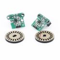
- This module is used by the motor node to measure the car's speed by keeping track of how many revolutions the rotary revolves around the sensor. The rotary contains twenty hole slits, so a full revolution will "tick" the sensor twenty times.
Software Design
The motor node is designed to receive a desired speed and a desired steering angle from the driver node. These values will be used to adjust the RC Car's motor speed and servo motor angle to align with those requested values.
There are four public functions that are provided in the motor node.
1. void motors__init(void)
- This function is used by the periodic callback to initialize the required peripherals used to control the motor speed as well as the servo motor angle.
2. void motors__run(void)
- This function is used by the periodic callback to set the motor speed and the servo motor angle. This public function will invoke two private functions, motors__speed_handler() which handles the motor speed of the car, and motors__steering_handler() which handles the steering angle of the car.
- motors__speed_handler()
- This private function controls the RC Car's speed, which is calculated by measuring the circumference of the car's wheel and finding out how many times it rotates within a given time frame. Setting the time frame and obtaining the circumference of the wheel is trivial, however, obtaining the amount of rotations required additional effort. We used an HC-020K Wheel Encoder to measure how many times the wheel rotated around its axle and connected the +5V output to one of the SJ2's GPIO pins. This pin was then attached to an interrupt service, which incremented the static variable holding the number of times the wheel has rotated. The sample code to calculate the speed of the car is shown below.
    static int8_t motors__private_get_speed_kmh(void) {
      int8_t motor_speed = current_speed_kmh;
      uint64_t current_time_ms = sys_time__get_uptime_ms();
      uint64_t time_elapsed_ms = current_time_ms - wheel_encoder_previous_time_ms;

      if (time_elapsed_ms >= 100U) {
        wheel_encoder_previous_time_ms = current_time_ms;

        if (time_elapsed_ms > 0) {
          float number_of_wheel_cycles = (float)wheel_encoder_number_of_ticks / (float)WHEEL_ENCODER_TICKS_PER_CYCLE;
          float distance_travelled_cm = (float)(number_of_wheel_cycles * WHEEL_CIRCUMFERENCE_CM);

          motor_speed =
              (distance_travelled_cm / CENTIMETERS_IN_ONE_KILOMETER) / ((float)time_elapsed_ms / MILLISECONDS_IN_ONE_HOUR);

          wheel_encoder_number_of_ticks = 0U;

          if (MOTORS__DIRECTION_REVERSE == current_motor_direction) {
            motor_speed *= -1;
          }

        }
      }

    return motor_speed;
}- motors__steering_handler()
- This private function controls the RC Car's steering angle.
- The steering driver works in a similar way to how the motor driver works in the sense that it makes use of a digital to analog converter (DAC) to send signals to the motor transceiver to tell the car how much to steer. First, the motor node receives a CAN message through the CAN bus that contains a float value from within the range of -2.1 (full lock to the left) to 2.1 (full lock to the right). The steering driver then converts this float to an integer number used to write to the 12-bit DAC through I2C communication. Essentially, the range [-2.1, 2.1] which has 42 steps, is mapped to the range of [0, 4096] using the equation: (input + 2.1) * 10 * 4096 / 42.
3. void motors__set_speed_and_steering_values(dbc_MOTOR_VALUES_s *motor_values)
- This function is used by the CAN Bus Message Handler to set the desired speed and steering angle. When the CAN Bus Message Handler module receives a CAN package, it will decode the motor values and call this function. This function is also used by the MIA handler as well to stop the RC Car if it doesn't receive any CAN messages from the driver node ten times in a 10Hz periodic callback.
4. dbc_MOTOR_VALUES_TO_DRIVER_s motors__get_motor_values(void)
- This function is used by the CAN Bus Message Handler to transmit the current speed of the car.
Technical Challenges
- Electronic Speed Controller (ESC)
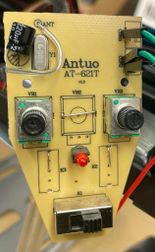
- When opening the RC car, the team found that the ESC was fully resined into the car's base. This prevented the team from directly controlling the ESC, so the team decided to control the RC car's speed and steering through the RC car's remote transceiver. The remote transceiver was taken apart and the team discovered that the user controlled the speed and steering through the use of two potentiometers, which sent specific voltage values to the transceiver's circuit and sent those values to the ESC remotely via Bluetooth. The team developed an internal DAC driver and an external DAC driver to send controlled voltage values to the transceiver to simulate the potentiometer output values.
- Wheel Encoder Issues
- During the integration of the wheel encoder, our team encountered various issues regarding its positioning on the car and its debouncing circuitry.
- Due to the shape of the RC car's plastic base, it was difficult to find a position on the car to place the wheel encoder such that it could accurately read the amount of revolutions the rotary wheel has made. The encoder must be placed near the axle of the wheel, however, there was no platform large enough to fix the encoder onto. The team purchased a metal "L" bracket and fixated the bracket onto one of the base's thin plastic platforms. This bracket was used as a new platform to mount the wheel encoder onto for better positioning and reading accuracy.
- Additionally, mounting the rotary wheel onto the axle was another issue. Initially, the rotary wheel had to be broken apart and crudely super-glued together. However, this solution resulted in a less accurate encoder reading due to the rotary being warped from the initial break. The team 3D printed a new rotary wheel in two separate pieces to resolve the warping issue from breaking it ourselves. This resulted in a more consistent, accurate encoder reading.
- Motor startup sequence
- Initially, when starting up the car, the team faced an issue where although voltage values are being sent to accelerate the car, the car would remain stationary. The solution to this issue was found in the user manual. According to the RC Car's user manual, both the acceleration and the steering triggers must be neutral when powering on the car. This means that when starting up, both the motor and the servo motor must be set to specific voltage values. The team measured the potentiometer's voltage value outputs when the triggers were in a neutral position and used those voltage values when starting up.
Geographical Controller
Hardware Design
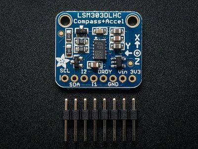
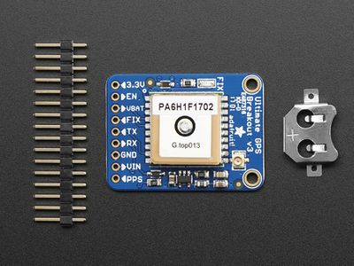
The two main sensors used were the Adafruit LSM303 Compass and Adafruit Ultimate GPS. The LSM303 is a combination of a magnetometer and accelerometer sensors, which are the two vital components of a tilt-compensated compass. Both sensors are also on the same chip and therefore reduces the placement and alignment requirements.
Software Design
The Sensor Node consists of 1 main control module: gps_controller.c and several supporting drivers: compass.c, lsm303.c, and gps.c.
1. The gps_controller module handles calling the drivers to read data, process the data, and then calls the dbc_encode_and_send functions in order to send results on the CAN bus.:
- 'Void geo__process_gps_data(void)’
- The main function used in 10Hz callback to consistently read gps, magnetometer, and accelerometer data. It then calculates heading angle and bearing angle before sending all raw data and angles onto the CAN bus.
- 'Void geo__transformation_mag(float uncalibrated_acc_values[3])'
- Geo__transformation functions are used to apply calibration and bias values o sensor data. The hard-coded calibration and bias values are from Magmaster or Magneto calibration programs
2. The gps module provides basic functions to setup and interface with the Adafruit Ultimate GPS module.:
- ‘Void gps__configure(void)'
- This function is responsible for getting all the ultrasonic sensors, storing them in a local sensor struct created by the auto-generated code from the DBC file, and return that struct back to the user
- ‘Void gps__GPGGA_convert_to_degrees(const char *val_char, const char *cardinal)’
- This function is responsible for converting GPGGA format values into degrees. By default GPGGA format sends latitude and longitude in degree minutes.
3. The lsm303 module provides basic functions to setup and interface with the Adafruit LSM303 Compass module.:
- ‘bool lsm303__read_mag(void)’
- This function is nearly identical to the read_accel function. The read functions will format and write the values read into a custom struct of floats.
- 'lsm303_MagData_t lsm303__tilt_comp_mag(lsm303_MagData_t MagData_nocomp, lsm303_AccelData_t accel_reading)': This function provides tilt-compensated magnetometer reading values when given magnetometer and accelerometer readings
4. The compass module provides contains the compass calculations required for geo node.:
- 'float compass__get_bearing_angle(float src_latitude, float src_longitude, float dst_latitude, float dst_longitude)'
- This function takes in the latitude and longitude of the current location and desired destination and calculates the bearing angle using the igismap reference
- 'float compass__get_heading_angle(float cur_Mag_x, float cur_Mag_y)': This function takes in magnetometer readings and generates a heading angle. To get a tilt-compensated heading angle, the input magnetometers need to be tilt-compensated using the accelerometer values
- 'float compass__get_remaining_distance(float src_latitude, float src_longitude, float dst_latitude, float dst_longitude)': This function takes in the latitude and longitude of the current location and desired destination and applies the haversine formula to calculate distance
Technical Challenges
- Inconsistent Heading:
- The heading issue turned out to be related to the PCB integration. When testing the compass separately connecting by only dupont cables it performed as expected. This raises the importance of “unit testing” components, before integration to more easily locate issues in integration.
- Compass Calibration:
- For our compass calibration we ended up implementing all the algorithms we could find. The two most prominent methods are the “simple” two-point style calibration and the magmaster / magneto ardruino method. The magmaster method was the more extensive of the two and not extremely complicated when utilizing the Arduino program developed by YuriMat. Prior to being able to use this software, getting a hand-held magnetic compass is crucial. These are extremely more useful than any compass application on the Android of Apple store. A hand-held compass allowed us to locate a spot with little to no interference, making it a good location to preform calibration.
Communication Bridge Controller & OLED
OLED Hardware Design
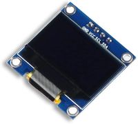
The hardware design of the OLED module was very straightforward as the physical display uses i2c to communicate to the SJ2Board. We needed to determine which board the OLED should be extended from, and we thought it would be best to extend it from the driver node to be able to have access to what the driver itself is receiving from the CAN bus. Below is an image of the OLED module that we used.
OLED Software Design
The goal with our software design was to have one function being called periodically that would handle displaying all of the messages that we wanted to display. We created a high-level function called display_all_data_on_OLED, which would be called in the 1 Hz periodic callback. We wanted to create the software this way because it would allow us to write the periodic_callback once and not alter it when we wanted to change what was displayed. This type of development also made unit-testing the functions much easier than if we had to continuously alter the function.
We eventually used this mentality of separating functions to improve unit-testing ability to minimize bugs throughout the OLED code modules. This allowed us to easily write, test, and verify the oled code worked properly.
OLED Technical Challenges
Initially there were a handful of problems that stemmed from a general lack of documentation. Based on the names of the pin connections, we knew the OLED used i2c; however, we did not know any of the pertinent addresses due to the lack of documentation. Once we found reliable source documentation, we were able to display messages on the OLED, but this led us to what values we wanted to display and what process would be best to get them from the system. Once this was decided, we were able to successfully display pertinent information on to the OLED display.
During one of our code reviews, we realized that the code was incredibly bloated, and a handful of functions were very long. We decided to separate functionality into five main components: oled, display, get_values_to_display, process_data, and debug_statements. Each of these modules is focused on a specific portion of the previous iteration of bloated code. The oled module handles the initialization of the OLEDdisplay itself as well as all of the functions that are required for the OLED to function properly, display is a high-level module that simply calls functions that would display the desired information, get_values_to_display is a module that would attain the values that would need to be displayed, process_data is a module that processes data from the CAN bus, and debug_statements is a module that creates the statements themselves to be displayed.
Bridge Hardware Design
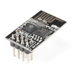
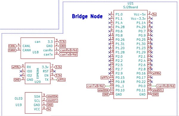
The group chose to use WiFi communication as opposed to Bluetooth as the means of having communication between the application and the RC Car itself. We decided to use WiFi because one of our teammates had experience working with the wifi previously. The ESP8266 is interfaced with the SJ2 board through UART protocol.
Bridge Software Design
The Bridge Node is crucial in our project in which it reads data from other Nodes and sends it through Wifi to the apps, as well as reading signals sent from the app. There are 3 main functions in the periodic_callbacks.c that operates the Bridge Node.
+bridge_module__publish_data(callback_count): In this function, the Bridge Node publishes all data receives from other Nodes to the app.
+bridge_module__handle_incoming_messages(): This function handles the incoming data from the app and sends appropriate signals to other Node through the CAN bus.
+bridge_module__read_data(): This functions read the data from the ESP8266
Bridge Technical Challenges
- UART protocol: Our teammate who is responsible for implementing the ESP module does not have experience with basic embedded communication protocols. Thus, at the beginning he has a hard time understanding the UART protocol which is used for the ESP module. We went through the UART lecture on SocialLedge to make sure he has a solid understanding of UART.
- Data parsing: Data can be received through UART and it needs to be parsed correctly in order for us to use it. We made many "headers", which are keywords that the string begins with. We can then use these beginning keywords to classify the messages and send out the appropriate message on the CAN bus.
- Bridge Node and Sensor Node integration: When we designed our PCB, we combined the Sensor Node and the Bridge Node together. However, our code is incompatible to integrate fully. It would require us to rewrite everything from scratch. Thus, we used the same PCB and just separate the Bridge Node outside and use a protoboard to fit it with our setting
Driver Module
The Driver node is responsible for receiving data from the Sensor Node, Geo Node, and Bridge Node to issue appropriate commands to the Motor Node.
Hardware Design
1. CAN Transceiver
- This module will be used to communicate with the Motor Node by sending the Motor command through CAN communication protocol. In order to send the correct Motor command, the Driver Node also receives data from the Sensor Node, the GEO Node, and the Bridge Node. The CAN transceiver will be powered by a +3.3V source with its Transmit Line (Tx) connected to GPIO Pin P0.1 and its Receive Line (Rx) connected to GPIO Pin P0.0.
Software Design
The Driver Node receive and decode these 4 CAN frame:
- SONAR_VALUES: Ultrasonic sensor values from the Sensor Node.
- COMPASS_HEADING_DISTANCE: Geo-location information(Heading angle, Bearing angle, and Distance to destination) from the GEO Node.
- GPS_DESTINATION_REACHED: A bit to signify if it has reached its destination from the GEO Node.
- DRIVE_START: Used to Start or Stop sending the Motor frame to the Motor Node, this frame is received from the Bridge Node.
At the top level, the periodic_callbacks.c only calls 3 functions in the 10hz periodic callback:
- (void)can_bus_message_handler__receive(): Receive and decode CAN dataframe from the Sensor Node, GEO Node, and the Bridge Node. Then generate the Motor command based on those frames.
- (void)can_bus_message_handler__transmit(): Transmit the Motor command onto the CAN bus.
- (void)can_handler__manage_mia_10hz(): Check if any dataframe is missing and handle it via the MIA handlers
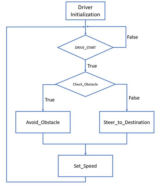
The main part of the Driver Node is how it can generate the appropriate Motor Command given all the data from the other 3 nodes. The workflow(Represented by the above diagram) can be understood as:
- Check if there is any obstacle based on the Sensor values
- If there is an obstacle, update the steering value to avoid the obstacle
- If not, update the steering to head to destination based on the Geo Node frame
- Set the speed of the car
In our final version of (RC)², there are a few flags that are used to set the speed:
- start_driving flag: This flag is set/clear by the Start/Stop signal or the Destination_reached signal: It will set the car speed to 0
- steering_to_destination: If this flag is set, the car is currently steering to the destination, and the speed is set at our medium default speed (when steer you should slow down)
- very_close_to_destination: This flag is set based on the Distance left to the destination received from the GEO node. If this flag is set, the speed will also be set to the medium default speed so that it will not overshoot the destination.
- Else, the car speed is set to the default speed to drive to the destination.
Technical Challenges
- Steer to destination angle
- We tried different methods to calculate the shortest direction (clockwise/counter-clockwise) to steer. Our first attempt was working but it was a very heavy function and it did not work in 1 case when the Bearing is in the 4th quadrant and the Heading angle is in the 1st quadrant. We also found out that many algorithms online also miscalculated the wrong direction to steer in that case! After some math check, we arrived at an elegant solution taking the Heading and Bearing angle, compare the distance_to_left and distance_to_right, which can be then used to infer the shorter direction to steer.
- Jumpy Heading angle
- Our car at the end has an issue with the Heading angle being very noisy when the car moves. Besides working on the GEO Node itself to have a more stable Heading angle, we also try to limit the effect of the changing Heading angle in the Driver Node. What I did was having the driver_logic check if the new Heading angle is greater than the current Heading angle by a certain threshold. This helps with the jumpy Heading values. However, it presents another bug if the car changes the Heading angle very sudden, it can cause the Heading angle value in the Driver Node to freeze! This is not a good fix, however, it works in our case with stabilizing the Heading angle.
- Controlling sequence
- The sequence of processing the data affects our car obstacle avoidance at one time. We moved the decode_SONAR_VALUE to be on top of everything else and it improves our avoidance! This is a minor change but I think one needs to pay some attention if your car does not steer to avoid fast enough.
Mobile Application
https://gitlab.com/rc-2/rc_car2_android_app
Software Design
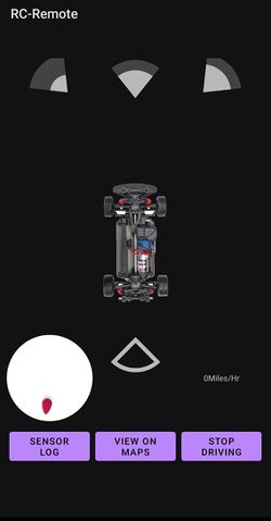
We initially wanted to create an iOS application because the majority of the group had iPhones, but we created an android application instead using Android Developer Studio as no one had a Mac for iOS development. Below are images of the different screens in our application.
Technical Challenges
- Interfacing ESP8266 & Smart Phone - MQTT Protocol
- The process of implementing the MQTT protocol was not straight foward. Connecting to the MQTT server via ESP8266 was also difficult since everytime the wifi access point changed it would need to be reflashed with a new IP address. Keeping a static mobile hotspot to allow the ESP8266 to connect solved us having to reflash. To solve the MQTT connection problem, we set up the MQTT server using a docker on google cloud, which worked for communication to the MQTT server.
- Flashing ESP8266
- Flashing the ESP8266 with custom software to handle MQTT was a complicated process. Using a straight connection to the ESP8266 through GPIO we were unable to flash the module without failing. Buying a 3rd party breakout board with an Arduino UNO allowed us to easily flash the ESP8266 on the first try.
- Random Crashes
- Diagnosing android app crashes is a little more difficult than the standard SJ2 development typically done in class. When reasons for crash are not as obvious a useful debug tool, Android Vitals, will allow you to view stack traces leading up to a crash. These tools are valuable when debugging seemingly random crashes during application usage.
Conclusion
In the end, (RC)² was unable to fully autonomously navigate itself after being given a location. The only remaining issue we had was properly stabilizing the compass. During the car's journey towards its specified destination, the car continuously drove in circles due to the erratic values being obtained from the compass. The team attempted various software patches, however, was unable to resolve the issue in time. Although the car did not completely work, the (RC)² project was a valuable learning experience. It provided a great opportunity for us to learn and practice code modularization in a large project. With unit testing, it gave each sub-team a level of confidence when it was time to start the integration process. The project taught us the importance of being able to work remotely and have also taught us the importance of maintaining a balanced schedule. Overall, this project has provided us with many practical skills and experiences that we can carry into the field.
We learned about:
- CAN Communication Protocol
- Code modularization
- YAGNI
- DBC Files and auto codegen
- Unit Testing is the way to go!
- Debugging
- Mobile Application Design
- PCB Design
- Real-life testing is needed on top of Unit testing
- And a whole lot more UNIT TESTING!
Project Video
- YouTube Video Link: Initial RC² Run
Project Source Code
- Git Project Link: RC²
Advice for Future Students
- Make sure to get a head start on the Compass and Geo Navigation implementation. This portion of the project requires extensive research to understand and numerous rounds of testing to ensure the calibration is set properly. The RC² team underestimated the amount of effort that would be required for this portion of the project. Although our car was able to run and avoid obstacles, the car could not be fully autonomous without properly knowing where to go. Be careful with having magnets around when testing!!!
- Work with an Electronic Speed Controller(ESC) that is not resined into the car's platform! When the RC² team took apart the car, we realized that the ESC has been completely resined into the car's platform. This restrained us from directly controlling the ESC and forced us to control the ESC through the transmit controller. This made the car jerky when adjusting its speed. If your RC Car's ESC is resined into the platform, we suggest completely removing the ESC and purchasing a new one to integrate with your RC car.
- Please starts early with the PCB design so that you can have a solid hardware. By doing this, you will have more time playing with the threshold that can affected the driving experience tremendously
- Choose quality components! Treat yourself as an engineer that is paid $100/hour so don't waste your time on cheap, unreliable parts.
- Buy Extra components! Incase one of them fail to calibrate, gives out bad values on the demo day.
- Make sure that your power source is stable. The GPS and Compass module is extremely sensitive so if your power source is unstable, it can negatively affect your data.
- We found this out at the very end of the class when testing our car. It is good to have a physical compass. Using your phone as the compass can affect the compass if it is close to the car.
Acknowledgement
- Chyavan Phadke for assisting us in the process of designing the PCB.
- Belinda Nguyen for providing us a location to meet and work in.
- Professor Preetpal Kang for his valuable knowledge and advice throughout the semester
- And all of our team members for putting a collaborative effort this semester in developing (RC)²
References
Bearing Angle Formula; Note: See comments for correction to formula
