Difference between revisions of "F20: Son of a Gun"
Proj user3 (talk | contribs) |
Proj user3 (talk | contribs) |
||
| (118 intermediate revisions by the same user not shown) | |||
| Line 1: | Line 1: | ||
| + | |||
| + | |||
| + | |||
| + | |||
| + | |||
| + | [[File:SOG_Game.jpg||330px|caption|right|]] | ||
| + | |||
[[File:Ezgif.com-gif-maker.gif||330px|caption|right|]] | [[File:Ezgif.com-gif-maker.gif||330px|caption|right|]] | ||
| + | |||
| + | |||
== Abstract == | == Abstract == | ||
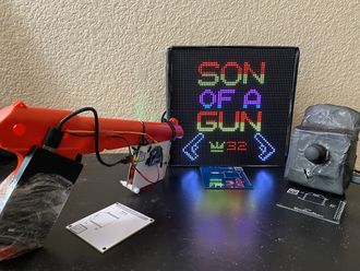
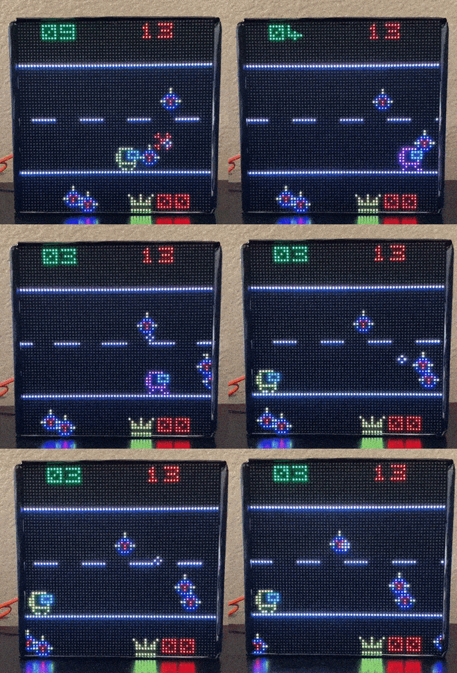
| − | '''''Son Of A Gun''''' is a shooting game inspired by the evergreen classics ''[https://en.wikipedia.org/wiki/Duck_Hunt Duck Hunt]'' and ''[https://en.wikipedia.org/wiki/Virtua_Cop_2 Virtua Cop 2]''. There | + | '''''Son Of A Gun''''' is a shooting game inspired by the evergreen classics ''[https://en.wikipedia.org/wiki/Duck_Hunt Duck Hunt]'' and ''[https://en.wikipedia.org/wiki/Virtua_Cop_2 Virtua Cop 2]''. It is a two player game. There is one ''friend'' object (a yellow robot) and severaly ''enemy'' objects will coming in the way of the ''friend''. The ''friend'' is controlled using a Joystick Controller by Player-1 and Player-2 will control the ''aim cursor'' with a Gun to shoot the ''enemy'' objects to help Player-1. Player-2 has to avoid shooting the ''friend'' or else the ''friend'' will lose the health. |
| − | |||
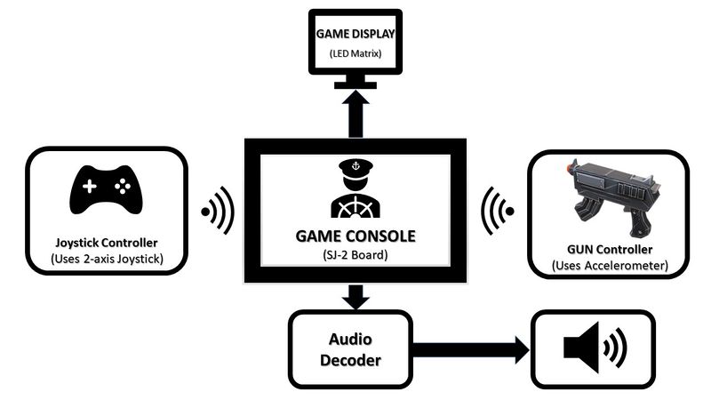
[[File:Block_Diagram_SOG.jpg|800px|thumb|center|Block Diagram of Game Son Of a Gun]] | [[File:Block_Diagram_SOG.jpg|800px|thumb|center|Block Diagram of Game Son Of a Gun]] | ||
== Objectives & Introduction == | == Objectives & Introduction == | ||
| − | + | ||
| + | Objective is to create a game in which 2 players play in unison to save the friend robot. Enemy move along the 2D screen in pseudo random fashion. The movement of these enemies depend on the game play level being played currently. | ||
| + | *Friend robot can be moved on screen using a 2 axis joystick. The joystick communicates with the console connected to the LED module over zigbee. | ||
| + | *Second player can shoot the enemy object using a wireless gun. The gun, too, communicates with the central console using zigbee. | ||
| + | *Friend can move to stay away from enemy object. Also, it can collect extra life which appears along with enemies at random time. | ||
| + | *Each time the enemy touches the friend robot or the second player shoots at the friend robot, the robot looses one life. | ||
| + | *Difficulty level is a function of time. Game level increases by one at every 45 seconds. | ||
| + | *Number of enemies, their speed and randomness of movement increases with increase in game play level. | ||
| + | *Game play continues as long as the number of life left is more than 0. Game over once the user looses all the lives. | ||
| + | *Game resets after this and display the high score and current score. | ||
=== Team Members & Responsibilities === | === Team Members & Responsibilities === | ||
* Tejas Pidkalwar | * Tejas Pidkalwar | ||
| + | ** Zigbee Driver and Communication APIs | ||
| + | ** LED Driver APIs | ||
| + | ** Gameplay Level manager algorithm | ||
| + | ** Wireless interface and message synchronization | ||
| + | ** Wiki Page Updated | ||
* Tirth Pandya | * Tirth Pandya | ||
| + | ** Developed MP3 decoder driver | ||
| + | ** Interfaced Joystick and Accelerometer with SJTwo | ||
| + | ** PCB Designing | ||
| + | ** LED object movements and frames | ||
| + | ** LED object data structures | ||
| + | ** Wiki page update | ||
* Nimit Patel | * Nimit Patel | ||
| + | ** LED driver | ||
| + | ** Object detection and Collision | ||
| + | ** Cursor detection and kill logic. | ||
| + | ** Game play logic. | ||
| + | ** Accelerometer and Joystick logic. | ||
| + | ** Wiki page update. | ||
== Schedule == | == Schedule == | ||
| Line 175: | Line 209: | ||
* 12/05 | * 12/05 | ||
| | | | ||
| − | <font color="green"> Completed | + | *<font color = "green"> Completed |
| + | *<font color = "green"> Completed | ||
| + | *<font color = "green"> Completed | ||
| + | *<font color = "green"> Completed | ||
| + | *<font color = "green"> Completed | ||
| + | *<font color = "green"> Completed | ||
|- | |- | ||
!scope="row" | 11 | !scope="row" | 11 | ||
| Line 195: | Line 234: | ||
* 12/01 | * 12/01 | ||
* 12/10 | * 12/10 | ||
| + | * 12/12 | ||
| | | | ||
| − | <font color="green"> Completed | + | *<font color = "green"> Completed |
| + | *<font color = "green"> Completed | ||
| + | *<font color = "green"> Completed | ||
| + | *<font color = "green"> Completed | ||
| + | *<font color = "green"> Completed | ||
| + | *<font color = "green"> Completed | ||
| + | *<font color = "blue"> In Progress | ||
|- | |- | ||
!scope="row" | 12 | !scope="row" | 12 | ||
| Line 212: | Line 258: | ||
* 12/16 | * 12/16 | ||
| | | | ||
| − | <font color="green"> Completed | + | *<font color = "blue"> In Progress |
| + | *<font color = "green"> Completed | ||
| + | *<font color = "green"> Completed | ||
| + | *<font color = "green"> Completed | ||
|- | |- | ||
|} | |} | ||
| Line 290: | Line 339: | ||
== Design & Implementation == | == Design & Implementation == | ||
| − | |||
Son of A Gun project is designed using C language, FreeRTOS OS, LPC4078 based SJ-2 board, Zigbee transceivers, joystick, SJ-2's onboard accelerometer. To enclose hardware together we designed PCBs for each module viz Game Console, Joystick controller, and Gun controller. | Son of A Gun project is designed using C language, FreeRTOS OS, LPC4078 based SJ-2 board, Zigbee transceivers, joystick, SJ-2's onboard accelerometer. To enclose hardware together we designed PCBs for each module viz Game Console, Joystick controller, and Gun controller. | ||
=== Hardware Design === | === Hardware Design === | ||
| − | |||
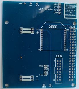
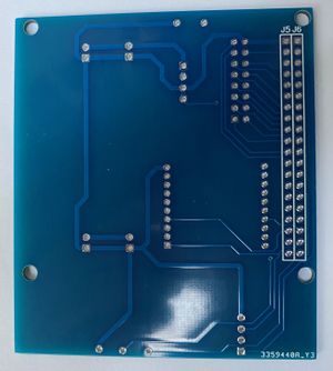
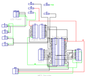
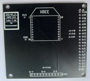
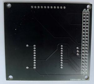
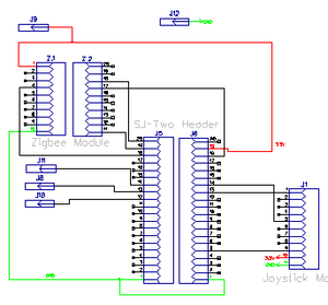
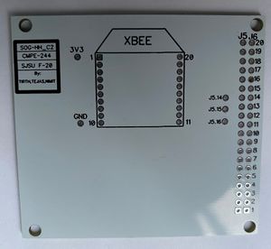
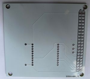
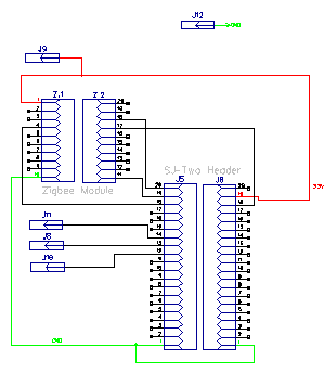
| − | SOG game has 3 modules communicating wirelessly over Zigbee. Each module is controlled by an SJ-2 board and its onboard peripherals. We designed PCBs to enclose each module in a compact and elegant way. | + | SOG game has 3 modules communicating wirelessly over Zigbee. Each module is controlled by an SJ-2 board and its onboard peripherals. We designed PCBs to enclose each module in a compact and elegant way and placed and a printing order on JLCPCB's portal. JLCPCB delivered printed PCB in 3-4 days. |
1) Game Console's PCB: | 1) Game Console's PCB: | ||
| − | [[File:Game_console_PCB_1.jpg| | + | |
| − | [[File:Game_console_PCB_2.jpg| | + | [[File:Game_console_PCB_1.jpg|275px|thumb|left|Game Console PCB 1]] |
| + | |||
| + | [[File:Game_console_PCB_2.jpg|300px|thumb|right|Game Console PCB 2]] | ||
| + | |||
| + | [[File:Master console.png |275px|thumb|center|Game Console Schematic]] | ||
| + | |||
| + | |||
| + | |||
| + | |||
| + | |||
| + | |||
| + | |||
2) Joystick Controller's PCB: | 2) Joystick Controller's PCB: | ||
| + | |||
| + | [[File:Joystick_controller_PCB_1.jpg|300px|thumb|left|Joystick Controller PCB 1]] | ||
| + | |||
| + | [[File:Joystick_controller_PCB_2.jpg|300px|thumb|right|Joystick Controller PCB 2]] | ||
| + | |||
| + | [[File:Hh schematic joystick.png |300px|thumb|center|Joystick Controller Schematic]] | ||
3) Gun Controller's PCB: | 3) Gun Controller's PCB: | ||
| + | |||
| + | [[File:GUN_controller_PCB_1.jpg|300px|thumb|left|Gun Controller PCB 1]] | ||
| + | |||
| + | [[File:GUN_controller_PCB_2.jpg|300px|thumb|right|Gun Controller PCB 2]] | ||
| + | |||
| + | [[File:Hh schemetic gun.png |300px|thumb|center|Gun Controller Schematic]] | ||
=== Hardware Interface === | === Hardware Interface === | ||
| − | + | Our project on a high level is implemented in two modules, viz. Game console and game controllers. | |
| + | |||
| + | '''Game Console:''' | ||
| + | |||
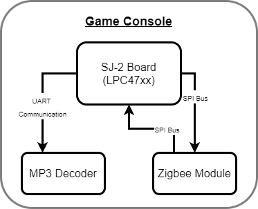
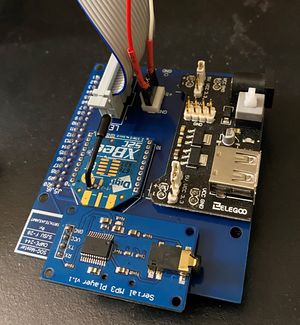
| + | The game console is driven by an SJ-2 (LPC4078) board and its peripherals. This board takes input wirelessly over Zigbee protocol. Zigbee module communicates a received message via SPI bus interface to SJ-2 board. Sj-2 board operates based on the received input data and outputs the audio-related information to the MP3 decoder via UART bus. Below is the block diagram and the actual hardware picture for the Game Console: | ||
| + | |||
| + | [[File:Game console block diagram.png|600px|thumb|left|Game Console Block diagram]] | ||
| + | |||
| + | [[File:Game console hardware.jpg|300px|thumb|center|Game Console hardware]] | ||
| + | |||
| + | |||
| + | '''Game Controller:''' | ||
| + | |||
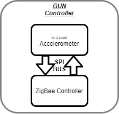
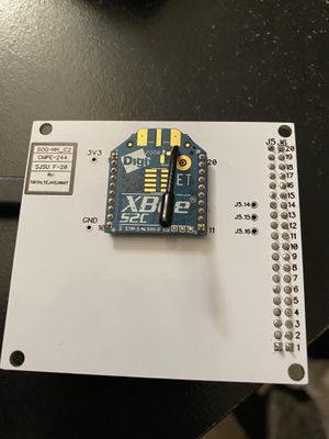
| + | The game controllers are also driven by the SJ-2 board and send data wirelessly over Zigbee communication. Below are the block diagrams and hardware image for the controllers: | ||
| + | |||
| + | [[File:Gun Controller block diagram.png|600px|thumb|left|Controller Block diagram]] | ||
| + | |||
| + | [[File:Controller hardware.jpg|300px|thumb|center|Controller hardware]] | ||
| + | |||
| + | === Software Design and Algorithms === | ||
| − | === | + | ==== LED Matrix Driver and Graphics algorithm ==== |
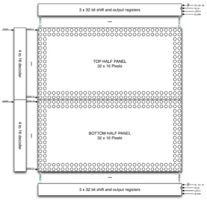
| − | + | SOG project uses a 64x64 LED matrix by Sparkfun for gameplay graphics display. Each LED pixel can be controlled individually and can operate with 8 colors. To operate the LED matrix, we can select 2 rows at a time, each from 2 planes. Planes are made by dividing 64 rows into 2 halves, i.e. first 32 rows in plane 1 and the remaining 32 rows in plane 2. Five signals (viz. A, B, C, D, and E) which are connected to 5 GPIOs of the SJ-2 board are used to select rows from each plane. R1, G1, B1 signals with 64-bit registers are used to address individual led from the selected row in plane 1. Similarly, R2, G2, B2 signals used to address individual led from the selected row in plane 2. A single clock is interfaced to these 6 64bit shift registers. Hence, at one clock signal, we fill and enable a column corresponding to two selected rows. Once the clocking and register shifting is done, the data need to be latched to the register which in turn enables the corresponding LED. | |
| − | + | [[File:LED Matrix organization.png|300px|thumb|Center|64x64 LED Matrix Driver]] | |
| − | Our approach to the software design involved the use of eight different tasks for the various moving elements of our gameplay. Seven of these tasks are dedicated to updating the matrix buffer of size 32x64 which is just a two-dimensional array holding the R2, G2, B2 and R1, G1, B1 values. The ninth task has the highest priority which is used to refresh the display. This task | + | Our approach to the software design involved the use of eight different tasks for the various moving elements of our gameplay. Seven of these tasks are dedicated to updating the matrix buffer of size 32x64 which is just a two-dimensional array holding the R2, G2, B2 and R1, G1, B1 values. The ninth task has the highest priority which is used to refresh the display. This task gets the latest values from the matrix buffer and is used to display a frame of the game on the LED Matrix display. The matrix buffer is constantly updated in real-time by the other seven tasks such as: |
# Title Screen: | # Title Screen: | ||
#* Used to initially display the title screen | #* Used to initially display the title screen | ||
| Line 329: | Line 418: | ||
# Detect Gunshot | # Detect Gunshot | ||
#* Move cursor based on the accelerometer value received over Zigbee | #* Move cursor based on the accelerometer value received over Zigbee | ||
| − | #* When trigger is pressed, verify the object in Friend and Enemy Plane | + | #* When the trigger is pressed, verify the object in Friend and Enemy Plane |
#* If object detected, track which object is detected along with its nature i.e. Friend or Enemy | #* If object detected, track which object is detected along with its nature i.e. Friend or Enemy | ||
#* Take appropriate action. Reduce Life or kill enemy object and increase score. | #* Take appropriate action. Reduce Life or kill enemy object and increase score. | ||
| Line 337: | Line 426: | ||
The last task is the refresh display task mentioned above. This task includes a display function that controls the Latch, Clock, Output Enable pins of the LED Matrix display. This function reads the matrix buffer and extracts the R2, G2, B2, R1, G1, B1 values using shift operators. | The last task is the refresh display task mentioned above. This task includes a display function that controls the Latch, Clock, Output Enable pins of the LED Matrix display. This function reads the matrix buffer and extracts the R2, G2, B2, R1, G1, B1 values using shift operators. | ||
| + | |||
| + | [[File:Collision detection friend enemy.png|300px|thumb|left|Collision detection of friend enemy]] | ||
| + | |||
| + | [[File:Collect_life.png|300px|thumb|right|64x64 LED Matrix Driver]] | ||
| + | |||
| + | [[File:Pointer_Detection.png|300px|thumb|center|Gun Pointer Detection]] | ||
| + | |||
| + | |||
| + | |||
| + | |||
| + | |||
| + | '''Code snippet''' | ||
| + | |||
| + | The following structure is used to track all the objects visible on the screen. Co-ordinates of the objects along with the nature i.e. friend, enemy or life can be tracked using this structure. | ||
| + | <syntaxhighlight lang="c"> | ||
| + | |||
| + | |||
| + | typedef enum { FRIEND_OBJECT = 0, ENEMY_OBJECT, LIFE_OBJECT, BLAST_ENEMY } OBJECT_NATURE; | ||
| + | |||
| + | struct object_details { | ||
| + | int row, column; | ||
| + | OBJECT_NATURE obj_nature; | ||
| + | bool status; | ||
| + | }; | ||
| + | |||
| + | </syntaxhighlight> | ||
| + | |||
| + | All the objects are initialized using the below function. Random function is used to initialize enemy at random positions so that the game does not remain predictable for the user. | ||
| + | |||
| + | <syntaxhighlight lang="c"> | ||
| + | void initialize_object_details() { | ||
| + | int random; | ||
| + | life = 15; | ||
| + | enemy_score = 0; | ||
| + | // void_function_t draw_enemy_pointer = &draw_enemy; | ||
| + | for (int i = 0; i < number_of_objects; i++) { | ||
| + | random = rand() % 63; | ||
| + | onscreen_objects_struct[i].row = random; | ||
| + | random = rand() % 63; | ||
| + | |||
| + | if (i == 0) { | ||
| + | onscreen_objects_struct[i].status = true; | ||
| + | onscreen_objects_struct[i].obj_nature = FRIEND_OBJECT; | ||
| + | onscreen_objects_struct[i].column = 0; | ||
| + | } else if (i == 1) { | ||
| + | onscreen_objects_struct[i].obj_nature = LIFE_OBJECT; | ||
| + | onscreen_objects_struct[i].status = false; | ||
| + | onscreen_objects_struct[i].column = random; | ||
| + | |||
| + | } else { | ||
| + | onscreen_objects_struct[i].obj_nature = ENEMY_OBJECT; | ||
| + | onscreen_objects_struct[i].status = false; | ||
| + | onscreen_objects_struct[i].column = random; | ||
| + | } | ||
| + | |||
| + | // onscreen_objects_struct[i].obj_nature = rand() % 2; | ||
| + | } | ||
| + | } | ||
| + | </syntaxhighlight> | ||
| + | |||
| + | One of the many randomizer functions used to move the enemy objects on screen. The extent of movement is changed depending on the active level being played. A standard random number generator is used to generate row and column values for the enemy objects. These values are also tested for border conditions. This helps in visualizing smooth entry and exit of enemy objects on the screen. Enemy objects enter from right most part and travel towards left side. Once it reaches the left most part,a smooth transitioning effect can be observed, instead of outright disappearing the object. | ||
| + | <syntaxhighlight lang="c"> | ||
| + | void randomizer_objects_level_3() { | ||
| + | int random; | ||
| + | for (int i = first_moving_object; i < number_of_objects; i++) { | ||
| + | random = rand() % 3; | ||
| + | random = random - 1; | ||
| + | onscreen_objects_struct[i].row += random; | ||
| + | if ((onscreen_objects_struct[i].row < (row_boundary_upper - 8)) || | ||
| + | (onscreen_objects_struct[i].row > (row_boundary_lower + 8))) | ||
| + | onscreen_objects_struct[i].row = row_boundary_upper + (rand() % (row_boundary_lower - row_boundary_upper)); | ||
| + | random = rand() % 2; | ||
| + | random = random - 2; | ||
| + | onscreen_objects_struct[i].column += random; | ||
| + | if ((onscreen_objects_struct[i].column < -8) || (onscreen_objects_struct[i].column > 71)) { | ||
| + | onscreen_objects_struct[i].column = 55 + (rand() % 8); | ||
| + | } | ||
| + | // printf("%d %d %d\n", onscreen_objects_struct[i].row, onscreen_objects_struct[i].column, i); | ||
| + | } | ||
| + | } | ||
| + | </syntaxhighlight> | ||
| + | |||
| + | ==== Zigbee Module Driver ==== | ||
| + | |||
| + | To design wireless communication between controllers and game console we used Zigbee module XBee S2C by Digi. One ZigBee connected to the game console is configured as coordinator and the other two connected to controllers are configured as a router. Out of two modes of Zigbee communication we used API mode since in API mode a message frame helps to synchronize messages from two receivers. To configure Zigbee modules we used XCTU software to update Zigbee firmware and initial configuration. | ||
| + | |||
| + | In API mode each frame consists of 18 bytes of the header information, including the sender's address and checksum for data integrity. To interface Zigbee with the master board (SJ-2) we initially incorporated UART communication but its slower data transfer rate became a bottleneck for the Game console module's Zigbee receiver and resulted in a slower response to the controller's action. Thus we moved to use the SPI interface which provided the data transfer rate of almost 3 Mbps and the result was clearly visible with negligible latency in response to the controller's action. | ||
| + | |||
| + | ''' Code snippet for zigbee's data transfer API: ''' | ||
| + | |||
| + | <syntaxhighlight lang="c"> | ||
| + | void zigbee__data_transfer(uint8_t *data, size_t data_size) { | ||
| + | data_size = data_size + data_frame_header[Length_byte_LSB]; | ||
| + | // printf(" Total data size frame headers is %x\n", data_frame_header[Length_byte_LSB]); | ||
| + | data_frame_header[Length_byte_LSB] = data_size & 0xFF; | ||
| + | data_frame_header[Length_byte_MSB] = (data_size >> 8) & 0xFF; | ||
| + | uint8_t checksum = calculate_checksum(data); | ||
| + | |||
| + | // printf("\nChecksum value is %x", checksum); | ||
| + | // printf(" Total data size except checksum byte is %x ", data_size); | ||
| + | zigbee__cs(); | ||
| + | (void)ssp2__exchange_byte(data_frame_header[Start_byte]); | ||
| + | (void)ssp2__exchange_byte(data_frame_header[Length_byte_MSB]); | ||
| + | (void)ssp2__exchange_byte(data_frame_header[Length_byte_LSB]); | ||
| + | |||
| + | // Iterate for all the frame bytes which are included in data size | ||
| + | for (int i = Frame_type_byte; i < data_size + Frame_type_byte; i++) { | ||
| + | if (i < Frame_header_size) { | ||
| + | (void)ssp2__exchange_byte(data_frame_header[i]); | ||
| + | // printf(" %x\t", data_frame_header[i]); | ||
| + | } else if (i < data_size + Frame_type_byte) { | ||
| + | (void)ssp2__exchange_byte(*data); | ||
| + | // printf(" %x\t", *data); | ||
| + | data++; | ||
| + | } | ||
| + | } | ||
| + | (void)ssp2__exchange_byte(checksum); | ||
| + | zigbee__ds(); | ||
| + | // Resetting the frame length parameter in frame header | ||
| + | data_frame_header[Length_byte_LSB] = 0xE; | ||
| + | data_frame_header[Length_byte_MSB] = 0x0; | ||
| + | } | ||
| + | |||
| + | </syntaxhighlight> | ||
| + | |||
| + | |||
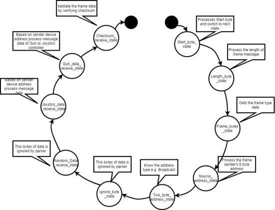
| + | To receive the API message frame from Zigbee and process it, the receiver controller needs to parse through the complete header message to verify the sender's address and calculate the checksum of the complete message. For that, we designed a state machine, which traverses through each state as it processes each section from the frame header. | ||
| + | |||
| + | ''' Code snippet for zigbee's receiver and frame parsers states: ''' | ||
| + | |||
| + | <syntaxhighlight lang="c"> | ||
| + | typedef enum zigbee_receive_state { | ||
| + | Start_byte_state, | ||
| + | Length_byte_state, | ||
| + | Frame_bytes_state, | ||
| + | Sender_address_state, | ||
| + | Two_byte_address_state, | ||
| + | Ignore_byte_state, | ||
| + | Random_Data_receive_state, | ||
| + | Joystick_data_receive_state, | ||
| + | Gun_data_receive_state, | ||
| + | Checksum_receive_state, | ||
| + | Max_states, | ||
| + | } zigbee_receive_state; | ||
| + | |||
| + | </syntaxhighlight> | ||
| + | |||
| + | ''' State machine for Zigbee receiver: ''' | ||
| + | |||
| + | [[File:Zigbee_receiver_state_machine.png|550px|thumb|center|Zigbee Receiver State Machine]] | ||
| + | |||
| + | |||
| + | ==== Gun Controller Module ==== | ||
| + | |||
| + | SOG gameplay's prime objective is to kill the enemy using a gun. Gun controller operates using SJ-2's onboard accelerometer. We are mounting an SJ-2 board on a gun at a position dedicated to Gun's magazine. To send X-Y coordinate to the LED matrix, we are using 2 of X, Y and Z coordinates measurements from the accelerometer. | ||
| + | |||
| + | [[File:CmpE244_S18_Detectable_Accelerations.png|400px|thumb|center|Accelerometer Detection]] | ||
| + | |||
| + | The MMA8452Q which is a smart low-power, three-axis, capacitive micromachined accelerometer with 12 bits of resolution is used in our project. Accelerometers are electromechanical devices that are used to sense acceleration that can be of various forms, for instance, gravity. | ||
| + | |||
| + | ''' Code snippet for Accelerometer Calibration: ''' | ||
| + | |||
| + | <syntaxhighlight lang="c"> | ||
| + | acceleration__axis_data_s acceleration__get_averaged_data(uint8_t no_of_samples, uint16_t sensitivity) { | ||
| + | acceleration__axis_data_s axis_values = {0}; | ||
| + | |||
| + | int32_t x = 0, y = 0, z = 0; | ||
| + | for (int i = 0; i < no_of_samples; i++) { | ||
| + | axis_values = acceleration__get_data(); | ||
| + | x += axis_values.x; | ||
| + | y += axis_values.y; | ||
| + | z += axis_values.z; | ||
| + | } | ||
| + | axis_values.x = x / no_of_samples; | ||
| + | axis_values.y = y / no_of_samples; | ||
| + | axis_values.z = z / no_of_samples; | ||
| + | |||
| + | axis_values.x = 32 + ((axis_values.x * 32) / sensitivity); | ||
| + | if (axis_values.x <= 0) | ||
| + | axis_values.x = 0; | ||
| + | if (axis_values.x >= 63) | ||
| + | axis_values.x = 63; | ||
| + | axis_values.z = 32 + ((axis_values.z * 32) / sensitivity); | ||
| + | if (axis_values.z <= 0) | ||
| + | axis_values.z = 0; | ||
| + | if (axis_values.z >= 63) | ||
| + | axis_values.z = 63; | ||
| + | axis_values.y = 32 + ((axis_values.y * 32) / sensitivity); | ||
| + | if (axis_values.y <= 0) | ||
| + | axis_values.y = 0; | ||
| + | if (axis_values.y >= 63) | ||
| + | axis_values.y = 63; | ||
| + | |||
| + | return axis_values; | ||
| + | } | ||
| + | |||
| + | </syntaxhighlight> | ||
| + | |||
| + | To read the gun's button press, we are using GPIO interrupt. As soon as the button is pressed, interrupt raises the button press flag which gets transferred over the Zigbee. | ||
| + | |||
| + | [[File:Gun_controller_flow_chart.png|400px|thumb|center|Gun Controller flow chart]] | ||
| + | |||
| + | ==== Dual Axis Joystick ==== | ||
| + | A dual axis joystick is a combination of two potentiometers along with a SPST button. This project uses the joystick to control the movements of the ''friend'' object. In order to interface the joystick, the ADC channel inputs are used and the X-axis position and Y-axis position is acquired in the form of raw ADC values. These values are further mapped with the required sensitivity for the movement. The return values of the joystick data read API is bounded by the row and columns available on the LED matrix to restrict the X-Y positions. | ||
| + | |||
| + | Once the joystick data is ready, it is sent to the master console over the zigbee communication. The master console takes the joystick inputs and moves the ''friend'' accordingly. | ||
| + | |||
| + | ''' Code snippet for Joystick Interface: ''' | ||
| + | |||
| + | <syntaxhighlight lang="c"> | ||
| + | joystick__values_s joystick__get_value(void) { | ||
| + | joystick__values_s joystick_values = {0, 0}; | ||
| + | static joystick__values_s new_val = {32, 32}; | ||
| + | int x_raw, y_raw; | ||
| + | |||
| + | LPC_IOCON->P0_25 &= ~(0x98); | ||
| + | x_raw = adc__get_adc_value(ADC__CHANNEL_2); | ||
| + | joystick_values.x = map(x_raw, 0, 4096, 3, -2); | ||
| + | LPC_IOCON->P1_30 &= ~(0x98); | ||
| + | y_raw = adc__get_adc_value(ADC__CHANNEL_4); | ||
| + | joystick_values.y = map(y_raw, 0, 4096, -2, 3); | ||
| + | |||
| + | new_val.x = joystick_values.x + new_val.x; | ||
| + | if (new_val.x > 63) | ||
| + | new_val.x = 63; | ||
| + | if (new_val.x <= 0) | ||
| + | new_val.x = 0; | ||
| + | |||
| + | new_val.y = joystick_values.y + new_val.y; | ||
| + | if (new_val.y > 63) | ||
| + | new_val.y = 63; | ||
| + | if (new_val.y <= 0) | ||
| + | new_val.y = 0; | ||
| + | |||
| + | return new_val; | ||
| + | } | ||
| + | |||
| + | float map(long x, long in_min, long in_max, float out_min, float out_max) { | ||
| + | return (float)((x - in_min) * (out_max - out_min) / (in_max - in_min) + out_min); | ||
| + | } | ||
| + | |||
| + | </syntaxhighlight> | ||
| + | |||
| + | ==== MP3 Decoder ==== | ||
| + | The MP3 Decoder used in this project is operating on UART commands. The driver module has an SD card slot and the driver plays the MP3 files as per the commands received from the SD card. The decoder module operates at 9600 baud rate and there are a variety of UART commands that are 8-bytes in length. We have integrated multiple sounds as per the gameplay that includes a background music, gunshot, level transition effect and a game-over sound. The corresponding tasks or events update the mp3_deatils structure and the MP3 task checks in after variable ticks based on the customized vTaskDelays. | ||
| + | |||
| + | ''' Code snippet for MP3 structure and interface: ''' | ||
| + | |||
| + | <syntaxhighlight lang="c"> | ||
| + | |||
| + | typedef struct { | ||
| + | MP3_SOUNDS mp3_to_play; | ||
| + | uint32_t mp3_duration; | ||
| + | } mp3_details_s; | ||
| + | |||
| + | bool mp3__send_command(uint8_t command, uint16_t data) { | ||
| + | bool status = false; | ||
| + | uint8_t data_ub = (uint8_t)(data >> 8); | ||
| + | uint8_t data_lb = (uint8_t)(data); | ||
| + | mp3_uart_buffer[0] = 0x7e; | ||
| + | mp3_uart_buffer[1] = 0xff; | ||
| + | mp3_uart_buffer[2] = 0x06; | ||
| + | mp3_uart_buffer[3] = command; | ||
| + | mp3_uart_buffer[4] = 0x00; | ||
| + | mp3_uart_buffer[5] = data_ub; | ||
| + | mp3_uart_buffer[6] = data_lb; | ||
| + | mp3_uart_buffer[7] = 0xef; | ||
| + | |||
| + | for (int i = 0; i < 8; i++) { | ||
| + | uart__polled_put(UART__3, mp3_uart_buffer[i]); | ||
| + | } | ||
| + | return status = true; | ||
| + | } | ||
| + | </syntaxhighlight> | ||
| + | |||
| + | |||
| + | [[File:Mp3 flow chart.png|400px|thumb|center|MP3 flow chart]] | ||
=== Implementation === | === Implementation === | ||
| − | |||
| − | + | The game involves the use of two controllers: one with a 2-axis joystick and the other with an onboard accelerometer. Apart from that, there is an MP3 decoder that is interfaced over UART. | |
| − | + | '''Gameplay Controllers:''' | |
| − | + | The interfacing of 2 axis joystick is fairly easy. 2 ADCs and the job is done. For accelerometers too, getting values over I2C is a relatively easy task. The challenge to calibrate the motion of the aim cursor with the accelerometer indeed took some efforts to simulate a gun pointer. For the MP3 decoder, there are several MP3 files for various events such as a background theme song, gunshot, level-up sound effect, game-over sound effect etc. All these MP3 files were needed to be modified and the UART commands were synchronized with the corresponding events. | |
| − | + | Challenge lies in using the Zigbee, with low latency. The serial was initially used, however, was later abandoned and SPI was used for lower latency. To use SPI for interfacing the Zigbee module with the master controller, Zigbee uses an additional pin name ''Attn'', which tells the master to start communication. This helps in speeding up the data transfer. | |
| − | + | '''Game Console:''' | |
| − | + | Tracking the object onscreen is challenging as the game involves shooting objects. 3 virtual planes are maintained other than the RGB planes, which maintains the greyscale image of objects. Eg: Friend objects are drawn in the friend plane, enemy in the enemy plane, and life objects in the life plane. An intersection of these planes gives the overlap if it exists. Once the intersection is available, the nearest position of the enemy/plane is extracted from the structure and requisite action is taken henceforth. | |
| + | |||
| + | Objects move on the screen on a pseudo-random pattern. The variability of the movement is dependent upon the gave level. Once the number of life becomes zero, the over state is called in the gameplay. | ||
== Testing & Technical Challenges == | == Testing & Technical Challenges == | ||
| − | |||
| − | |||
| − | |||
| − | |||
1. Zigbee Drivers: We initially used UART communication(Max possible speed 115200bps)to interface the ZigBee controller to the master controller. With the overhead of size of the frame (21-22 bytes) to send just 2 bytes of data, we observed significantly delayed response at the receiver end. So, we had to change the interface to SPI communication (with a speed of 3 mbps), which being duplex with high speed helped to remove delayed response at the receiver end. | 1. Zigbee Drivers: We initially used UART communication(Max possible speed 115200bps)to interface the ZigBee controller to the master controller. With the overhead of size of the frame (21-22 bytes) to send just 2 bytes of data, we observed significantly delayed response at the receiver end. So, we had to change the interface to SPI communication (with a speed of 3 mbps), which being duplex with high speed helped to remove delayed response at the receiver end. | ||
| Line 363: | Line 726: | ||
2. Sending button press response over Zigbee: We had implemented GPIO interrupt on GUN controller, which periodically reads accelerometer values and send calibrated values console, and semaphore waiting task to send button press response. The button press was causing occur interrupt to give a semaphore to the button press sender task and was disturbing the RTOS task of calibrating accelerometer values while sending to the game console. To remove this disturbance, we removed the semaphore waiting task on GPIO interrupt and instead used regular accelerometer parameter sender task to send button press signal. | 2. Sending button press response over Zigbee: We had implemented GPIO interrupt on GUN controller, which periodically reads accelerometer values and send calibrated values console, and semaphore waiting task to send button press response. The button press was causing occur interrupt to give a semaphore to the button press sender task and was disturbing the RTOS task of calibrating accelerometer values while sending to the game console. To remove this disturbance, we removed the semaphore waiting task on GPIO interrupt and instead used regular accelerometer parameter sender task to send button press signal. | ||
| − | === | + | === Issues and Bugs Resolved === |
1. All the objects onscreen are tracked by using a structure file, which has co-ordinates of all the object, their status, shape, and other relevant information. When we call the draw function, the LED worked flawlessly for some time, after which the board would restart. This was because the structure would access out of bound value, which resulted in the board to restart. | 1. All the objects onscreen are tracked by using a structure file, which has co-ordinates of all the object, their status, shape, and other relevant information. When we call the draw function, the LED worked flawlessly for some time, after which the board would restart. This was because the structure would access out of bound value, which resulted in the board to restart. | ||
| Line 369: | Line 732: | ||
== Conclusion == | == Conclusion == | ||
| − | |||
| − | + | The project involved using different hardware and then integrating it with the controller to create the game. Creating API for various tasks involved in gameplay helps in the modularization of design. This proves especially useful, during debugging, where the problematic API can be easily isolated and this reduces the scope of code review required for each debugging. | |
| + | |||
| + | Always test the hardware before it is incorporated into your project. However, there might be a case wherein, the API is not available to test the hardware. This becomes especially tricky, wherein, to pinpoint an issue is either related to hardware or software. A fault LED matrix resulted in our team in a fortnight's worth of time, initially trying to debug the issue, and then waiting for the new part to be shipped to us. | ||
| + | |||
| + | While using wireless data communication modules, our main focus was to optimize latency, and frame packet overhead which leads us to try out multiple interface protocols and finally decided to go with SPI bus (3 Mbps). | ||
| − | + | Another critical aspect of gameplay was to incorporate objects which have multiple colors, when overlap each other, results in color mixing on the LED panel. To achieve that, we used virtual LED matrix planes and manipulated those using logical operations. | |
| − | + | To play multiple MP3 files in synchronization with gameplay is tricky as the MP3 decoder, we used, doesn't allow to play multiple files simultaneously. Therefore the MP3 file selections and changing the tracks with the gameplay requires some trial and error approach. | |
| − | + | To sum it up, creating this project from scratch gave us more practical exposure in building real-time embedded applications and we were successful in meeting our project expectations. We want to thank Prof Preetpal Kang for his constant motivation and guidance. | |
=== Project Video === | === Project Video === | ||
| − | + | *''[https://youtu.be/rAG525jPbs8 Son of a gun - Video]'' | |
=== Project Source Code === | === Project Source Code === | ||
| Line 387: | Line 753: | ||
== References == | == References == | ||
=== Acknowledgement === | === Acknowledgement === | ||
| − | + | We would like to thank Professor Preetpal Kang for an innovative course structure where we could learn and test our skills by making innovative games as a project. We were able to enhance our knowledge and put our skills in action while designing the game where we used various embedded devices, communication protocols and technologies. | |
=== References Used === | === References Used === | ||
| − | + | *''[https://www.freertos.org/a00106.html FreeRTOS APIs]'' | |
| + | *''[https://learn.sparkfun.com/tutorials/getting-started-with-the-smartled-shield-for-teensy?_ga=2.31041787.592122345.1608254696-576883430.1604974127 Sparkfun LED Matrix Guide]'' | ||
| + | *''[https://bikerglen.com/projects/lighting/led-panel-1up/ LED matrix Driver Guide]'' | ||
| + | *''[https://www.digi.com/resources/documentation/digidocs/pdfs/90000976.pdf Zigbee Datasheet]'' | ||
| + | *''[http://geekmatic.in.ua/pdf/Catalex_MP3_board.pdf MP3 Decoder Datasheet]'' | ||
=== Appendix === | === Appendix === | ||
You can list the references you used. | You can list the references you used. | ||
Latest revision as of 07:56, 18 December 2020
Contents
Abstract
Son Of A Gun is a shooting game inspired by the evergreen classics Duck Hunt and Virtua Cop 2. It is a two player game. There is one friend object (a yellow robot) and severaly enemy objects will coming in the way of the friend. The friend is controlled using a Joystick Controller by Player-1 and Player-2 will control the aim cursor with a Gun to shoot the enemy objects to help Player-1. Player-2 has to avoid shooting the friend or else the friend will lose the health.
Objectives & Introduction
Objective is to create a game in which 2 players play in unison to save the friend robot. Enemy move along the 2D screen in pseudo random fashion. The movement of these enemies depend on the game play level being played currently.
- Friend robot can be moved on screen using a 2 axis joystick. The joystick communicates with the console connected to the LED module over zigbee.
- Second player can shoot the enemy object using a wireless gun. The gun, too, communicates with the central console using zigbee.
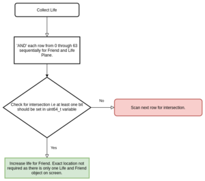
- Friend can move to stay away from enemy object. Also, it can collect extra life which appears along with enemies at random time.
- Each time the enemy touches the friend robot or the second player shoots at the friend robot, the robot looses one life.
- Difficulty level is a function of time. Game level increases by one at every 45 seconds.
- Number of enemies, their speed and randomness of movement increases with increase in game play level.
- Game play continues as long as the number of life left is more than 0. Game over once the user looses all the lives.
- Game resets after this and display the high score and current score.
Team Members & Responsibilities
- Tejas Pidkalwar
- Zigbee Driver and Communication APIs
- LED Driver APIs
- Gameplay Level manager algorithm
- Wireless interface and message synchronization
- Wiki Page Updated
- Tirth Pandya
- Developed MP3 decoder driver
- Interfaced Joystick and Accelerometer with SJTwo
- PCB Designing
- LED object movements and frames
- LED object data structures
- Wiki page update
- Nimit Patel
- LED driver
- Object detection and Collision
- Cursor detection and kill logic.
- Game play logic.
- Accelerometer and Joystick logic.
- Wiki page update.
Schedule
| Week# | Date | Task | Actual | Status |
|---|---|---|---|---|
| 1 |
09/23 - 09/29 |
|
|
|
| 2 |
09/30 - 10/06 |
|
|
|
| 3 |
10/07 - 10/13 |
|
|
|
| 4 |
10/14 - 10/20 |
|
|
|
| 5-7 |
10/21 - 11/10 |
|
|
|
| 8 |
11/11 - 11/17 |
|
|
|
| 9 |
11/18 - 11/24 |
|
|
|
| 10 |
11/25 - 12/1 |
|
|
|
| 11 |
12/2- 12/8 |
|
|
|
| 12 |
12/9 - 12/16 |
|
|
|
Parts List & Cost
General Parts
| Item # | Part | Vendor | Qty | Cost |
|---|---|---|---|---|
| 1 | 64x64 RGB LED Matrix | Sparkfun | 1 | $87.15 |
| 2 | SJTwo Boards | Amazon/SJSU | 3 | $150.00 |
| 3 | Zigbee Transreceiver | Amazon | 3 | $88.14 |
| 4 | Zigbee Adapter | Amazon | 1 | $14.16 |
| 5 | Two Axis Joystick | Amazon | 1 | $4.25 |
| 6 | 5V DC Power Supply | Amazon | 1 | $7.58 |
| 7 | MP3 Player | Amazon | 1 | $8.05 |
| 8 | Nintendo Gun | Amazon | 1 | $13.08 |
| 9 | PCB to Order | JLPCB | 3 | $27.03 |
| 10 | Miscellaneous | Excess Solution | 1 | $10.00 |
Design & Implementation
Son of A Gun project is designed using C language, FreeRTOS OS, LPC4078 based SJ-2 board, Zigbee transceivers, joystick, SJ-2's onboard accelerometer. To enclose hardware together we designed PCBs for each module viz Game Console, Joystick controller, and Gun controller.
Hardware Design
SOG game has 3 modules communicating wirelessly over Zigbee. Each module is controlled by an SJ-2 board and its onboard peripherals. We designed PCBs to enclose each module in a compact and elegant way and placed and a printing order on JLCPCB's portal. JLCPCB delivered printed PCB in 3-4 days.
1) Game Console's PCB:
2) Joystick Controller's PCB:
3) Gun Controller's PCB:
Hardware Interface
Our project on a high level is implemented in two modules, viz. Game console and game controllers.
Game Console:
The game console is driven by an SJ-2 (LPC4078) board and its peripherals. This board takes input wirelessly over Zigbee protocol. Zigbee module communicates a received message via SPI bus interface to SJ-2 board. Sj-2 board operates based on the received input data and outputs the audio-related information to the MP3 decoder via UART bus. Below is the block diagram and the actual hardware picture for the Game Console:
Game Controller:
The game controllers are also driven by the SJ-2 board and send data wirelessly over Zigbee communication. Below are the block diagrams and hardware image for the controllers:
Software Design and Algorithms
LED Matrix Driver and Graphics algorithm
SOG project uses a 64x64 LED matrix by Sparkfun for gameplay graphics display. Each LED pixel can be controlled individually and can operate with 8 colors. To operate the LED matrix, we can select 2 rows at a time, each from 2 planes. Planes are made by dividing 64 rows into 2 halves, i.e. first 32 rows in plane 1 and the remaining 32 rows in plane 2. Five signals (viz. A, B, C, D, and E) which are connected to 5 GPIOs of the SJ-2 board are used to select rows from each plane. R1, G1, B1 signals with 64-bit registers are used to address individual led from the selected row in plane 1. Similarly, R2, G2, B2 signals used to address individual led from the selected row in plane 2. A single clock is interfaced to these 6 64bit shift registers. Hence, at one clock signal, we fill and enable a column corresponding to two selected rows. Once the clocking and register shifting is done, the data need to be latched to the register which in turn enables the corresponding LED.
Our approach to the software design involved the use of eight different tasks for the various moving elements of our gameplay. Seven of these tasks are dedicated to updating the matrix buffer of size 32x64 which is just a two-dimensional array holding the R2, G2, B2 and R1, G1, B1 values. The ninth task has the highest priority which is used to refresh the display. This task gets the latest values from the matrix buffer and is used to display a frame of the game on the LED Matrix display. The matrix buffer is constantly updated in real-time by the other seven tasks such as:
- Title Screen:
- Used to initially display the title screen
- Display the current high score
- Life Display:
- Displays the number of life with friend function
- When health runs out, suspends all other tasks and displays end screen (Game Over)
- Move Friend:
- Move friend object depending on the inputs received from the 2-axis joystick over Zigbee
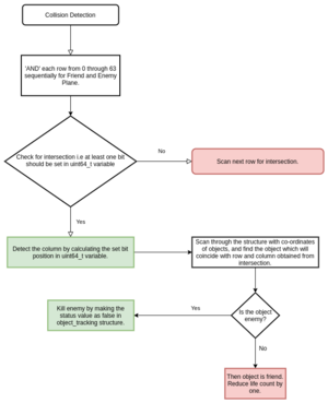
- Collision detection between the Friend and Enemy object.
- On overlap, reduce life by 1
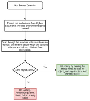
- Detect Gunshot
- Move cursor based on the accelerometer value received over Zigbee
- When the trigger is pressed, verify the object in Friend and Enemy Plane
- If object detected, track which object is detected along with its nature i.e. Friend or Enemy
- Take appropriate action. Reduce Life or kill enemy object and increase score.
- If missed shot then do nothing.
The last task is the refresh display task mentioned above. This task includes a display function that controls the Latch, Clock, Output Enable pins of the LED Matrix display. This function reads the matrix buffer and extracts the R2, G2, B2, R1, G1, B1 values using shift operators.
Code snippet
The following structure is used to track all the objects visible on the screen. Co-ordinates of the objects along with the nature i.e. friend, enemy or life can be tracked using this structure.
typedef enum { FRIEND_OBJECT = 0, ENEMY_OBJECT, LIFE_OBJECT, BLAST_ENEMY } OBJECT_NATURE;

struct object_details {
  int row, column;
  OBJECT_NATURE obj_nature;
  bool status;
};
All the objects are initialized using the below function. Random function is used to initialize enemy at random positions so that the game does not remain predictable for the user.
void initialize_object_details() {
  int random;
  life = 15;
  enemy_score = 0;
  // void_function_t draw_enemy_pointer = &draw_enemy;
  for (int i = 0; i < number_of_objects; i++) {
    random = rand() % 63;
    onscreen_objects_struct[i].row = random;
    random = rand() % 63;

    if (i == 0) {
      onscreen_objects_struct[i].status = true;
      onscreen_objects_struct[i].obj_nature = FRIEND_OBJECT;
      onscreen_objects_struct[i].column = 0;
    } else if (i == 1) {
      onscreen_objects_struct[i].obj_nature = LIFE_OBJECT;
      onscreen_objects_struct[i].status = false;
      onscreen_objects_struct[i].column = random;

    } else {
      onscreen_objects_struct[i].obj_nature = ENEMY_OBJECT;
      onscreen_objects_struct[i].status = false;
      onscreen_objects_struct[i].column = random;
    }

    // onscreen_objects_struct[i].obj_nature = rand() % 2;
  }
}
One of the many randomizer functions used to move the enemy objects on screen. The extent of movement is changed depending on the active level being played. A standard random number generator is used to generate row and column values for the enemy objects. These values are also tested for border conditions. This helps in visualizing smooth entry and exit of enemy objects on the screen. Enemy objects enter from right most part and travel towards left side. Once it reaches the left most part,a smooth transitioning effect can be observed, instead of outright disappearing the object.
void randomizer_objects_level_3() {
  int random;
  for (int i = first_moving_object; i < number_of_objects; i++) {
    random = rand() % 3;
    random = random - 1;
    onscreen_objects_struct[i].row += random;
    if ((onscreen_objects_struct[i].row < (row_boundary_upper - 8)) ||
        (onscreen_objects_struct[i].row > (row_boundary_lower + 8)))
      onscreen_objects_struct[i].row = row_boundary_upper + (rand() % (row_boundary_lower - row_boundary_upper));
    random = rand() % 2;
    random = random - 2;
    onscreen_objects_struct[i].column += random;
    if ((onscreen_objects_struct[i].column < -8) || (onscreen_objects_struct[i].column > 71)) {
      onscreen_objects_struct[i].column = 55 + (rand() % 8);
    }
    // printf("%d %d %d\n", onscreen_objects_struct[i].row, onscreen_objects_struct[i].column, i);
  }
}
Zigbee Module Driver
To design wireless communication between controllers and game console we used Zigbee module XBee S2C by Digi. One ZigBee connected to the game console is configured as coordinator and the other two connected to controllers are configured as a router. Out of two modes of Zigbee communication we used API mode since in API mode a message frame helps to synchronize messages from two receivers. To configure Zigbee modules we used XCTU software to update Zigbee firmware and initial configuration.
In API mode each frame consists of 18 bytes of the header information, including the sender's address and checksum for data integrity. To interface Zigbee with the master board (SJ-2) we initially incorporated UART communication but its slower data transfer rate became a bottleneck for the Game console module's Zigbee receiver and resulted in a slower response to the controller's action. Thus we moved to use the SPI interface which provided the data transfer rate of almost 3 Mbps and the result was clearly visible with negligible latency in response to the controller's action.
Code snippet for zigbee's data transfer API:
void zigbee__data_transfer(uint8_t *data, size_t data_size) {
  data_size = data_size + data_frame_header[Length_byte_LSB];
  // printf("  Total data size frame headers is %x\n", data_frame_header[Length_byte_LSB]);
  data_frame_header[Length_byte_LSB] = data_size & 0xFF;
  data_frame_header[Length_byte_MSB] = (data_size >> 8) & 0xFF;
  uint8_t checksum = calculate_checksum(data);

  // printf("\nChecksum value is %x", checksum);
  // printf("  Total data size except checksum byte is %x   ", data_size);
  zigbee__cs();
  (void)ssp2__exchange_byte(data_frame_header[Start_byte]);
  (void)ssp2__exchange_byte(data_frame_header[Length_byte_MSB]);
  (void)ssp2__exchange_byte(data_frame_header[Length_byte_LSB]);

  // Iterate for all the frame bytes which are included in data size
  for (int i = Frame_type_byte; i < data_size + Frame_type_byte; i++) {
    if (i < Frame_header_size) {
      (void)ssp2__exchange_byte(data_frame_header[i]);
      // printf(" %x\t", data_frame_header[i]);
    } else if (i < data_size + Frame_type_byte) {
      (void)ssp2__exchange_byte(*data);
      // printf(" %x\t", *data);
      data++;
    }
  }
  (void)ssp2__exchange_byte(checksum);
  zigbee__ds();
  // Resetting the frame length parameter in frame header
  data_frame_header[Length_byte_LSB] = 0xE;
  data_frame_header[Length_byte_MSB] = 0x0;
}
To receive the API message frame from Zigbee and process it, the receiver controller needs to parse through the complete header message to verify the sender's address and calculate the checksum of the complete message. For that, we designed a state machine, which traverses through each state as it processes each section from the frame header.
Code snippet for zigbee's receiver and frame parsers states:
typedef enum zigbee_receive_state {
  Start_byte_state,
  Length_byte_state,
  Frame_bytes_state,
  Sender_address_state,
  Two_byte_address_state,
  Ignore_byte_state,
  Random_Data_receive_state,
  Joystick_data_receive_state,
  Gun_data_receive_state,
  Checksum_receive_state,
  Max_states,
} zigbee_receive_state;
State machine for Zigbee receiver:
Gun Controller Module
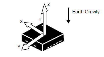
SOG gameplay's prime objective is to kill the enemy using a gun. Gun controller operates using SJ-2's onboard accelerometer. We are mounting an SJ-2 board on a gun at a position dedicated to Gun's magazine. To send X-Y coordinate to the LED matrix, we are using 2 of X, Y and Z coordinates measurements from the accelerometer.
The MMA8452Q which is a smart low-power, three-axis, capacitive micromachined accelerometer with 12 bits of resolution is used in our project. Accelerometers are electromechanical devices that are used to sense acceleration that can be of various forms, for instance, gravity.
Code snippet for Accelerometer Calibration:
acceleration__axis_data_s acceleration__get_averaged_data(uint8_t no_of_samples, uint16_t sensitivity) {
  acceleration__axis_data_s axis_values = {0};

  int32_t x = 0, y = 0, z = 0;
  for (int i = 0; i < no_of_samples; i++) {
    axis_values = acceleration__get_data();
    x += axis_values.x;
    y += axis_values.y;
    z += axis_values.z;
  }
  axis_values.x = x / no_of_samples;
  axis_values.y = y / no_of_samples;
  axis_values.z = z / no_of_samples;

  axis_values.x = 32 + ((axis_values.x * 32) / sensitivity);
  if (axis_values.x <= 0)
    axis_values.x = 0;
  if (axis_values.x >= 63)
    axis_values.x = 63;
  axis_values.z = 32 + ((axis_values.z * 32) / sensitivity);
  if (axis_values.z <= 0)
    axis_values.z = 0;
  if (axis_values.z >= 63)
    axis_values.z = 63;
  axis_values.y = 32 + ((axis_values.y * 32) / sensitivity);
  if (axis_values.y <= 0)
    axis_values.y = 0;
  if (axis_values.y >= 63)
    axis_values.y = 63;

  return axis_values;
}
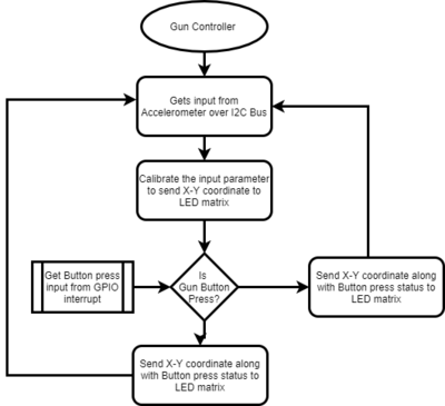
To read the gun's button press, we are using GPIO interrupt. As soon as the button is pressed, interrupt raises the button press flag which gets transferred over the Zigbee.
Dual Axis Joystick
A dual axis joystick is a combination of two potentiometers along with a SPST button. This project uses the joystick to control the movements of the friend object. In order to interface the joystick, the ADC channel inputs are used and the X-axis position and Y-axis position is acquired in the form of raw ADC values. These values are further mapped with the required sensitivity for the movement. The return values of the joystick data read API is bounded by the row and columns available on the LED matrix to restrict the X-Y positions.
Once the joystick data is ready, it is sent to the master console over the zigbee communication. The master console takes the joystick inputs and moves the friend accordingly.
Code snippet for Joystick Interface:
joystick__values_s joystick__get_value(void) {
  joystick__values_s joystick_values = {0, 0};
  static joystick__values_s new_val = {32, 32};
  int x_raw, y_raw;

  LPC_IOCON->P0_25 &= ~(0x98);
  x_raw = adc__get_adc_value(ADC__CHANNEL_2);
  joystick_values.x = map(x_raw, 0, 4096, 3, -2);
  LPC_IOCON->P1_30 &= ~(0x98);
  y_raw = adc__get_adc_value(ADC__CHANNEL_4);
  joystick_values.y = map(y_raw, 0, 4096, -2, 3);

  new_val.x = joystick_values.x + new_val.x;
  if (new_val.x > 63)
    new_val.x = 63;
  if (new_val.x <= 0)
    new_val.x = 0;

  new_val.y = joystick_values.y + new_val.y;
  if (new_val.y > 63)
    new_val.y = 63;
  if (new_val.y <= 0)
    new_val.y = 0;

  return new_val;
}

float map(long x, long in_min, long in_max, float out_min, float out_max) {
  return (float)((x - in_min) * (out_max - out_min) / (in_max - in_min) + out_min);
}
MP3 Decoder
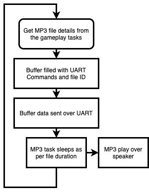
The MP3 Decoder used in this project is operating on UART commands. The driver module has an SD card slot and the driver plays the MP3 files as per the commands received from the SD card. The decoder module operates at 9600 baud rate and there are a variety of UART commands that are 8-bytes in length. We have integrated multiple sounds as per the gameplay that includes a background music, gunshot, level transition effect and a game-over sound. The corresponding tasks or events update the mp3_deatils structure and the MP3 task checks in after variable ticks based on the customized vTaskDelays.
Code snippet for MP3 structure and interface:
typedef struct {
  MP3_SOUNDS mp3_to_play;
  uint32_t mp3_duration;
} mp3_details_s;

bool mp3__send_command(uint8_t command, uint16_t data) {
  bool status = false;
  uint8_t data_ub = (uint8_t)(data >> 8);
  uint8_t data_lb = (uint8_t)(data);
  mp3_uart_buffer[0] = 0x7e;
  mp3_uart_buffer[1] = 0xff;
  mp3_uart_buffer[2] = 0x06;
  mp3_uart_buffer[3] = command;
  mp3_uart_buffer[4] = 0x00;
  mp3_uart_buffer[5] = data_ub;
  mp3_uart_buffer[6] = data_lb;
  mp3_uart_buffer[7] = 0xef;

  for (int i = 0; i < 8; i++) {
    uart__polled_put(UART__3, mp3_uart_buffer[i]);
  }
  return status = true;
}
Implementation
The game involves the use of two controllers: one with a 2-axis joystick and the other with an onboard accelerometer. Apart from that, there is an MP3 decoder that is interfaced over UART.
Gameplay Controllers:
The interfacing of 2 axis joystick is fairly easy. 2 ADCs and the job is done. For accelerometers too, getting values over I2C is a relatively easy task. The challenge to calibrate the motion of the aim cursor with the accelerometer indeed took some efforts to simulate a gun pointer. For the MP3 decoder, there are several MP3 files for various events such as a background theme song, gunshot, level-up sound effect, game-over sound effect etc. All these MP3 files were needed to be modified and the UART commands were synchronized with the corresponding events.
Challenge lies in using the Zigbee, with low latency. The serial was initially used, however, was later abandoned and SPI was used for lower latency. To use SPI for interfacing the Zigbee module with the master controller, Zigbee uses an additional pin name Attn, which tells the master to start communication. This helps in speeding up the data transfer.
Game Console:
Tracking the object onscreen is challenging as the game involves shooting objects. 3 virtual planes are maintained other than the RGB planes, which maintains the greyscale image of objects. Eg: Friend objects are drawn in the friend plane, enemy in the enemy plane, and life objects in the life plane. An intersection of these planes gives the overlap if it exists. Once the intersection is available, the nearest position of the enemy/plane is extracted from the structure and requisite action is taken henceforth.
Objects move on the screen on a pseudo-random pattern. The variability of the movement is dependent upon the gave level. Once the number of life becomes zero, the over state is called in the gameplay.
Testing & Technical Challenges
1. Zigbee Drivers: We initially used UART communication(Max possible speed 115200bps)to interface the ZigBee controller to the master controller. With the overhead of size of the frame (21-22 bytes) to send just 2 bytes of data, we observed significantly delayed response at the receiver end. So, we had to change the interface to SPI communication (with a speed of 3 mbps), which being duplex with high speed helped to remove delayed response at the receiver end.
2. Sending button press response over Zigbee: We had implemented GPIO interrupt on GUN controller, which periodically reads accelerometer values and send calibrated values console, and semaphore waiting task to send button press response. The button press was causing occur interrupt to give a semaphore to the button press sender task and was disturbing the RTOS task of calibrating accelerometer values while sending to the game console. To remove this disturbance, we removed the semaphore waiting task on GPIO interrupt and instead used regular accelerometer parameter sender task to send button press signal.
Issues and Bugs Resolved
1. All the objects onscreen are tracked by using a structure file, which has co-ordinates of all the object, their status, shape, and other relevant information. When we call the draw function, the LED worked flawlessly for some time, after which the board would restart. This was because the structure would access out of bound value, which resulted in the board to restart.
2. The object collision algorithm worked only if the object resided on column 32 and above on a 64 x 64 LED panel. On careful observation, it was noticed that the back end function which implemented the collision detection, used bit shifting of uint64 variables. The bits 32 through 63 all had value 0. The bit-shifting part was broken down into two 32 bit shift variables and then these two variables were &-ed together. Though, the comptroller processes all unit64 variable manipulation, the bit shifting one was a surprise and required intricate debugging to get the root cause of the API responding weirdly in an otherwise logical implementation of high-level logic.
Conclusion
The project involved using different hardware and then integrating it with the controller to create the game. Creating API for various tasks involved in gameplay helps in the modularization of design. This proves especially useful, during debugging, where the problematic API can be easily isolated and this reduces the scope of code review required for each debugging.
Always test the hardware before it is incorporated into your project. However, there might be a case wherein, the API is not available to test the hardware. This becomes especially tricky, wherein, to pinpoint an issue is either related to hardware or software. A fault LED matrix resulted in our team in a fortnight's worth of time, initially trying to debug the issue, and then waiting for the new part to be shipped to us.
While using wireless data communication modules, our main focus was to optimize latency, and frame packet overhead which leads us to try out multiple interface protocols and finally decided to go with SPI bus (3 Mbps).
Another critical aspect of gameplay was to incorporate objects which have multiple colors, when overlap each other, results in color mixing on the LED panel. To achieve that, we used virtual LED matrix planes and manipulated those using logical operations.
To play multiple MP3 files in synchronization with gameplay is tricky as the MP3 decoder, we used, doesn't allow to play multiple files simultaneously. Therefore the MP3 file selections and changing the tracks with the gameplay requires some trial and error approach.
To sum it up, creating this project from scratch gave us more practical exposure in building real-time embedded applications and we were successful in meeting our project expectations. We want to thank Prof Preetpal Kang for his constant motivation and guidance.
Project Video
Project Source Code
References
Acknowledgement
We would like to thank Professor Preetpal Kang for an innovative course structure where we could learn and test our skills by making innovative games as a project. We were able to enhance our knowledge and put our skills in action while designing the game where we used various embedded devices, communication protocols and technologies.
References Used
- FreeRTOS APIs
- Sparkfun LED Matrix Guide
- LED matrix Driver Guide
- Zigbee Datasheet
- MP3 Decoder Datasheet
Appendix
You can list the references you used.
