Difference between revisions of "F20: Treasure Diver"
Proj user5 (talk | contribs) |
Proj user5 (talk | contribs) (→LED Matrix) |
||
| (109 intermediate revisions by the same user not shown) | |||
| Line 38: | Line 38: | ||
'''Treasure Diver [https://gitlab.com/deharo27/treasure-diver GitLab]''' | '''Treasure Diver [https://gitlab.com/deharo27/treasure-diver GitLab]''' | ||
| − | '''Ameer Ali [https://gitlab.com/Ameer12 GitLab]''' | + | '''Ameer Ali [https://gitlab.com/Ameer12 GitLab] [https://www.linkedin.com/in/ameer-ali-13703b127/ LinkedIn]''' |
* LED Matrix Driver | * LED Matrix Driver | ||
* Matrix Graphics Development | * Matrix Graphics Development | ||
| Line 54: | Line 54: | ||
''' Nicholas Kaiser [https://gitlab.com/nichokaiser GitLab] [https://www.linkedin.com/in/nicholas-kaiser-20888713b/ LinkedIn]''' | ''' Nicholas Kaiser [https://gitlab.com/nichokaiser GitLab] [https://www.linkedin.com/in/nicholas-kaiser-20888713b/ LinkedIn]''' | ||
* HC05 Bluetooth Driver and Interface | * HC05 Bluetooth Driver and Interface | ||
| − | * Matrix Collision Detection Development | + | * Matrix Collision Detection Development & Level Design |
* CAD Enclosure Design | * CAD Enclosure Design | ||
* PCB Design | * PCB Design | ||
| Line 293: | Line 293: | ||
* Completed | * Completed | ||
* Completed | * Completed | ||
| − | * | + | * Completed |
|- | |- | ||
|} | |} | ||
| Line 544: | Line 544: | ||
== Design & Implementation == | == Design & Implementation == | ||
| − | |||
| − | |||
=== PCB Design === | === PCB Design === | ||
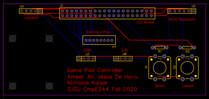
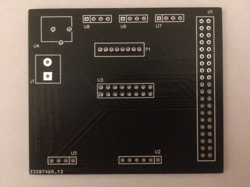
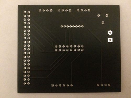
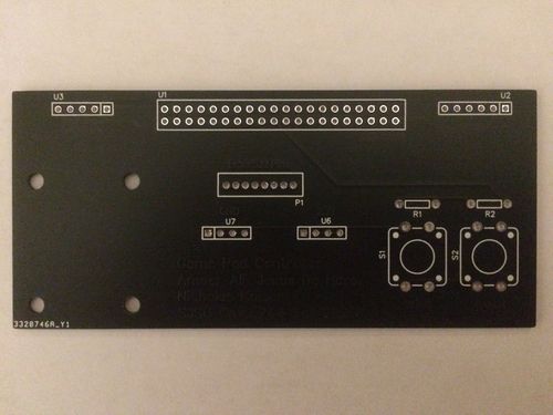
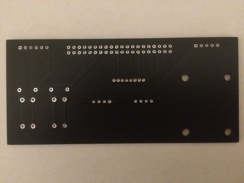
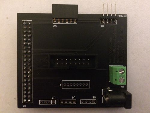
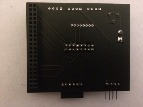
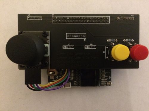
We chose EasyEDA as our PCB designing software since it is completely free to use with no trial period. Additionally, EasyEDA has a handy auto-routing feature, and the ability to create a PCB from a schematic. We designed two PCBs, one for our game pad controller and one for our matrix controller. First, we created separate schematics for both controllers that included all connections. We included extra GND, 3.3V, 5V, and SJ2 pins to accommodate any design changes down the road. We made these extra pins available as header pins on the PCBs. | We chose EasyEDA as our PCB designing software since it is completely free to use with no trial period. Additionally, EasyEDA has a handy auto-routing feature, and the ability to create a PCB from a schematic. We designed two PCBs, one for our game pad controller and one for our matrix controller. First, we created separate schematics for both controllers that included all connections. We included extra GND, 3.3V, 5V, and SJ2 pins to accommodate any design changes down the road. We made these extra pins available as header pins on the PCBs. | ||
| Line 684: | Line 682: | ||
| | | | ||
|} | |} | ||
| + | |||
| + | === Gameplay === | ||
| + | The matrix controller board has a total of 9 tasks running in order to transmit/receive bluetooth data, manage the LED matrix graphics, manage and update the game play, and play background music. | ||
| + | |||
| + | '''Matrix Controller Tasks''' | ||
| + | *Bluetooth Transmit - transmits controller type that the player selects in the options menu. | ||
| + | * Bluetooth Receive - receives the button presses and character movement direction data from the game pad. | ||
| + | * Update Board - updates the graphics displayed on the LED matrix. | ||
| + | * Draw Character - draws the character on the LED matrix based on the direction data received from the game pad. | ||
| + | * Collision Detection - calls our collision detection function which checks for all types of collision between game objects. | ||
| + | * Bullet Handler - draws and clears the bullet, and calls a function that checks for any collisions between the bullet and another game object. | ||
| + | * Character Status Handler - updates the character's "hurt" status, and decrements the air (health) bar. | ||
| + | * State Machine - calls our state machine function which manages our gameplay and screen transitions. | ||
| + | * Play Music - plays a specific MP3 track based on the current game state. | ||
| + | |||
| + | ==== State Machine ==== | ||
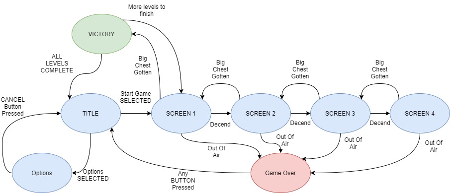
| + | A State Machine was developed to control the flow of the gameplay to both synchronize the games various Tasks but also give the player an enjoyable User Interface in between levels. | ||
| + | |||
| + | The main states of the game are: | ||
| + | #The title screen which lets people start the game or go to the options menu | ||
| + | #The option screen which lets users pick the volume level of the game or pick the control type they want to play with. | ||
| + | #The four screens which compromise a level | ||
| + | #The Victory Screen if the player happens to make it out of the level with the big chest | ||
| + | #The Game Over Screen which shows up if the player dies | ||
| + | |||
| + | As the player moves between States, various bool flags are checked based on various factors to see if the Player should be allowed to move on to the next screen. | ||
| + | |||
| + | ===== Software Design ===== | ||
| + | [[File:Treasure_diver_State_machine.jpg|center|1000px|thumb|The Game Logic of Treasure Diver]] | ||
| + | |||
| + | |||
| + | From this State Machine a Player begins in the TITLE State. From there they can move an on screen cursor using the Joystick Controls and select button to start the game or go to OPTIONS. From OPTIONS the player can also move the cursor to adjust volume, set the controls to motion controls or use the cancel button to return to TITLE. If start Game is selected then initial parameters for the Game are set and the task that draws and controls the Character is given the flag to turn on, SCREEN1 is then jumped to. Screen1 is where the game starts properly; within it the levels are drawn which include the enemies, obstacles, chests, and UI elements. The music that played on the TITLE screen will also swatch to active game music. The player must move to the bottom of the screen to descend into the next SCREEN2, SECREEN3, and finally SCREEN4. If the player collides with enemies or takes too long, they lose a bit of air. Once a player runs out of air on any of the SCREENs they get a GAMEOVER and return to the TITLE screen. Descending until SCREEN4, the player than has to collect a big Chest known as the Motherload. Once they collect that chest they can begin their ascent back up the SCREENS. If the Player manages to ascend past SCREEN1 they go the VICTORY screen. There score is displayed to them and they can hit any button to go the next level back on SCREEN1 or if they have competed all levels, back to the TITLE screen | ||
| + | |||
| + | ===== Implementation ===== | ||
| + | A switch case statement was used to implement this game as follows | ||
| + | |||
| + | switch (State) { | ||
| + | case TITLE: | ||
| + | switch (menu_select) { | ||
| + | case START_GAME: | ||
| + | SetInitalGameValues() | ||
| + | GoTo(Screen1) | ||
| + | case GO_TO_OPTIONS: | ||
| + | ResetCursor(); | ||
| + | GoTo(OPTIONS); | ||
| + | |||
| + | case SCREEN1: | ||
| + | drawLevel() | ||
| + | checkForAir() | ||
| + | CheckforCollsions() | ||
| + | if(at the bottom) | ||
| + | GoTo(SCREEN2 then to SCREEN3) | ||
| + | if(bigChestGotten && At the top) | ||
| + | VICTORRRRRY!!! | ||
| + | |||
| + | case SCREEN 2 ||3 | ||
| + | drawLevel() | ||
| + | checkForAir() | ||
| + | CheckforCollsions() | ||
| + | if(at the bottom) | ||
| + | GoTo(SCREEN2 || SCREEN3) | ||
| + | if(Big Chest Gotten) | ||
| + | ASCEND!!!! | ||
| + | |||
| + | case SCREEN4 | ||
| + | drawLevel() | ||
| + | checkForAir() | ||
| + | CheckforCollsions() | ||
| + | if(Big Chest Gotten) | ||
| + | ASCEND!!!! | ||
| + | |||
| + | case Victory | ||
| + | resetLevel&Charcter(); | ||
| + | if(More LEVELS?) | ||
| + | GoTo(Screen1) | ||
| + | else | ||
| + | GoTo(TITLE) | ||
| + | |||
| + | case Game over | ||
| + | resetLevel&Charcter(); | ||
| + | if(any BUTTON) | ||
| + | GoTo(TITLE) | ||
| + | |||
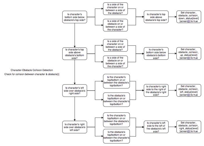
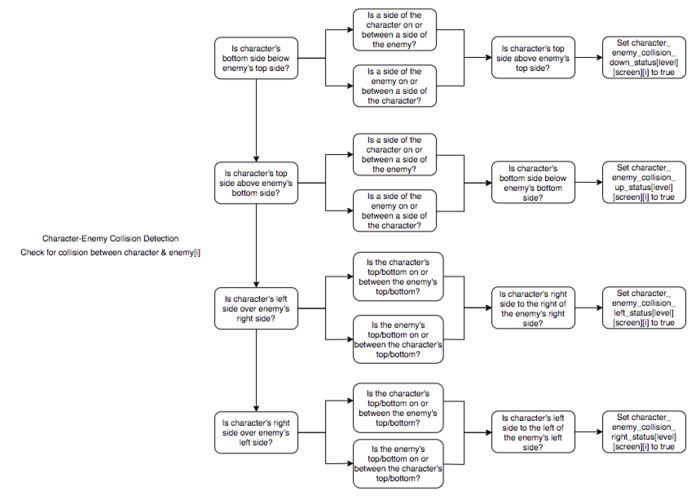
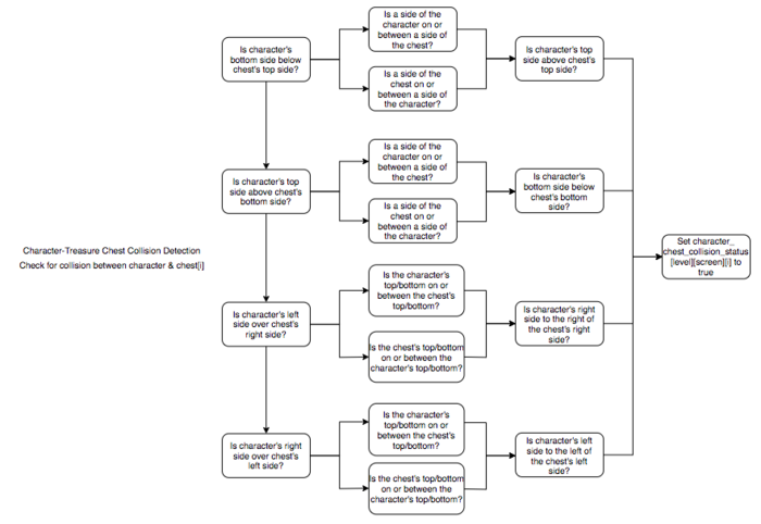
| + | ==== Collision Detection ==== | ||
| + | We have several different types of collisions that we check for in our treasure diver game: | ||
| + | * Character collides with obstacle | ||
| + | * Character collides with enemy | ||
| + | * Character collides with treasure chest | ||
| + | * Bullet collides with obstacle | ||
| + | * Bullet collides with enemy | ||
| + | |||
| + | We only check for collisions between objects where we need a specific event to occur. We don't check for a collision between the bullet and treasure chest for example because we don't need anything to happen in that case. The bullet just simply passes over the treasure chest and we don't need to deduct points, adjust air level, or anything. The collisions we do check for are ones that involve increasing/decreasing the player's score or air level, or have an effect on the game character's movement or status. | ||
| + | |||
| + | ===== Software Design ===== | ||
| + | The software design for each collision detection is described in the below flowcharts. The coding implementation is very lengthy and can be viewed in our GitLab repository. | ||
| + | |||
| + | [[File:Character-Obstacle_Collision_Detection.png|700px|center|Character-Obstacle Collision Detection]] | ||
| + | [[File:Character-Enemy_Collision_Detection.png|700px|center|Character-Enemy Collision Detection]] | ||
| + | [[File:Character-Treasure_Chest_Collision_Detection.png|700px|center|Character-Treasure Chest Collision Detection]] | ||
| + | [[File:Bullet-Obstacle_&_Bullet-Enemy_Collision_Detection.png|700px|center|Bullet-Obstacle & Bullet-Enemy Collision Detection]] | ||
=== RGB LED Matrix === | === RGB LED Matrix === | ||
| − | |||
| − | |||
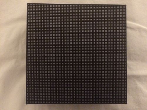
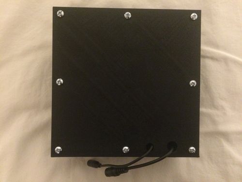
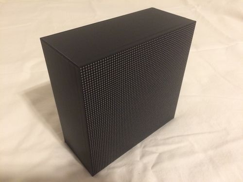
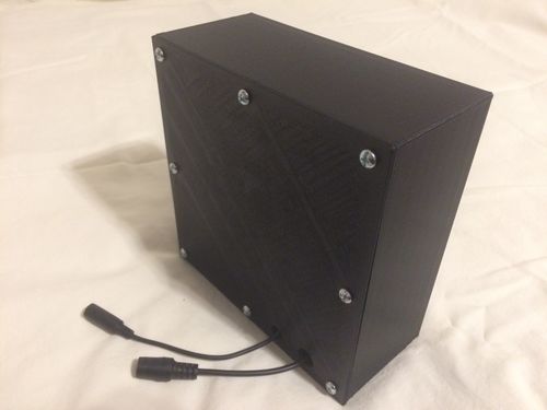
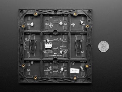
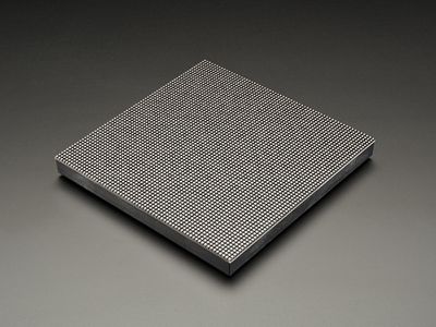
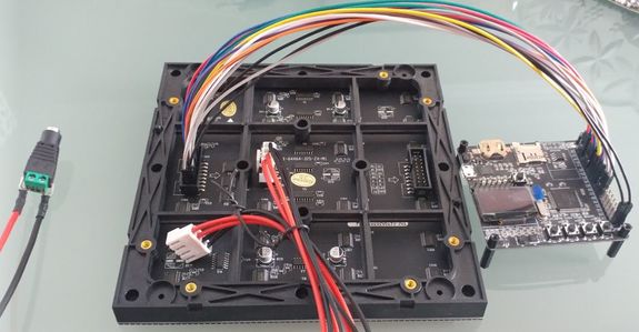
The Adafruit 64 X 64 LED matrix is responsible for displaying our Game elements to the player. | The Adafruit 64 X 64 LED matrix is responsible for displaying our Game elements to the player. | ||
| − | {| | + | {| style="margin-left: auto; margin-right: auto; border: none;" |
| − | |[[File:Treasure_Diver_LED_Matrix_backplate.jpg|400px| | + | |[[File:Treasure_Diver_LED_Matrix_backplate.jpg|400px|center]] |
| − | |[[File:Treasure_Diver_LED_Matrix_front.jpg|400px| | + | |[[File:Treasure_Diver_LED_Matrix_front.jpg|400px|center]] |
| − | |[[File:Treasure_diver_Raw_connection.jpg|575px| | + | |[[File:Treasure_diver_Raw_connection.jpg|575px|center]] |
|} | |} | ||
==== Hardware Design ==== | ==== Hardware Design ==== | ||
| − | |||
| − | |||
The Technical Specifications of our Matrix are as follows: | The Technical Specifications of our Matrix are as follows: | ||
*Brightness: 2800cd/square meter | *Brightness: 2800cd/square meter | ||
| Line 707: | Line 801: | ||
*Refresh Frequency: >=400HZ | *Refresh Frequency: >=400HZ | ||
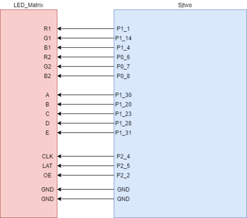
| − | Two pin Sets, Input & Output, are located on the back of the Matrix along with a 2 VCC & 2 GND pins. The power pins require an external power supply capable of providing 5v at a bare minimum 4A of current, which were hooked up to a power supply via the spade connectors provided with the board . Any less than that will be insufficient if the whole board must be lit up. The input pins are where the Sjtwo microcontroller connects to drive this board. The output Pins are for chaining together multiple matrices together and was unused for this project. To drive the matrix, | + | Two pin Sets, Input & Output, are located on the back of the Matrix along with a 2 VCC & 2 GND pins. The power pins require an external power supply capable of providing 5v at a bare minimum 4A of current, which were hooked up to a power supply via the spade connectors provided with the board . Any less than that will be insufficient if the whole board must be lit up. The input pins are where the Sjtwo microcontroller connects to drive this board. The output Pins are for chaining together multiple matrices together and was unused for this project. To drive the matrix, 14 GPIO pins were selected and made into output pins to control the input block of the matrix and two GND pins were used. The Pins and their connections are as follows: |
| − | [[File:Treasure_diver_Pin_connections. | + | [[File:Treasure_diver_Pin_connections.png|500px|right]] |
{| class="wikitable" | {| class="wikitable" | ||
|- | |- | ||
| Line 786: | Line 880: | ||
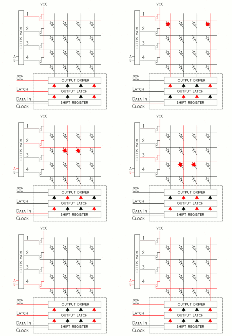
| + | The LEDs on the matrix are tricolor RGBs which means we have 8 color combinations at our disposal. Each color of each register is driven by one bit in a 3 bit shift register (3 bits for 3 colors). Those bits are then controlled by the RGB pins on the matrix. The board contains 4096 LEDs and has a scan rate of 1:32. A scan rate simply states what percentage of the LEDs are ON at any given time. So 4096/32 means that 128 LEDs are active on the board at any given time. This number divided by two neatly translates into 64 which is one row of our LED Matrix. The matrix is spilt into two halves, a lower and upper portion, and data is sent to those halves through the RGB pins. RGB1 denotes the upper 32 rows of the board and RGB2 denotes the bottom 32 rows. Of our 128 active LEDs, one row in the lower and upper portions is lit up each. The shift registers for each LED are daisy chained together to allow us to drive all LEDs in a row at the same time. To select '''which''' row we light up we use the 5 address pins A,B,C,D,E. 5 pins means we have 2^5 = 32 addressable rows we can select. | ||
| − | The | + | |
| + | {|style="margin-left: auto; margin-right: auto; border: none;" | ||
| + | |[[File:Treasure_diver_Scan_rate.gif|left|400px|thumb|LED selection process]] | ||
| + | |[[File:Scan116.gif|right|400px|thumb|Scan Rate of the Board]] | ||
| + | |} | ||
| + | |||
| + | |||
| + | The CLK pin is used to signal the arrival of one bit of data. The CLK must be toggled every time data is entered for one LED. The LATCH pin is used to signal the end of a row of data. Latch must be pulled high to control the Address Pins and then pulled back down to signal that the row has been selected. Output Enable (OE) is also set high with Latch to turn off the LEDs while the row is being selected and then clr low to turn them back on. | ||
==== Software Design ==== | ==== Software Design ==== | ||
==== Implementation ==== | ==== Implementation ==== | ||
| − | + | Now knowing what the hardware is like we can set the steps to draw one pixel on the board like so: | |
| + | #Represent what color you wish to draw to board using 3 bits | ||
| + | #Now determine if the LED you want to light up is in the UPPER or LOWER parts of the board and choose RGB1 or RGB2 pins respectively to set | ||
| + | #Set the bits and Clock them in with the rest of the LEDs by toggling the CLK (You can set the other LEDs to be off by clocking in zero) | ||
| + | #Once a full row has been entered, disable Output and set Latch High | ||
| + | #Using A,B,C,D,E pins, specify the row your target LED is on | ||
| + | #Set Latch back down to low and re-enable the Output | ||
| + | |||
| + | Representing our colors is done by driving (or not driving) the RGB pins on the matrix. R means red, G means blue, and B means blue and setting those bits together results in a color combo of the set set bits. Three pins means we only need three bits to represent the color we want. If the Sjtwo board is going to be picking the LEDs to draw it would be very handy if it had its own internal representation of the matrix. We can do so with a matrix! | ||
| + | |||
| + | uint8_t led_matrix[ROW_LENGTH][COL_LENGTH]; | ||
| + | |||
| + | In this 2d array we can say in each column of each row represent one LED. Now we also know that if an LED is located in the upper portion of the Board(Rows 0 - 31) its going to need to use the RGB1 and if in the lower portion (Rows 32-63) then its going to use the RGB2 pins. Since the color to write to the board is only 3 bits why not say the location of those bits determines which set of pins to drive? | ||
| + | |||
| + | //If RGB denotes my color and I want to light up red and my LED is at the first Row then I can say the entry for that matrix looks like | ||
| + | uint8_t color = 0b100 //Red, but not blue or green | ||
| + | led_matrix[0][desired_led] = color; | ||
| + | |||
| + | //But if my LED is in the upper portion I can shift the bits up three positions | ||
| + | led_matrix[35][desired_led] = color<<3; | ||
| + | |||
| + | This gives the Sjtwo board the ability to distinguish which Pins it must set to get the desired color at the desired location and so now we can update all the values of our board like so: | ||
| + | |||
| + | void led_driver__updateDisplay(void) { | ||
| + | for (uint8_t row = 0; row < 64; row++) { | ||
| + | for (uint8_t col = 0; col < 64; col++) { | ||
| + | if (led_matrix[row][col] & 0x1) { | ||
| + | gpio__set(B1); | ||
| + | } else { | ||
| + | gpio__reset(B1); | ||
| + | } | ||
| + | if (led_matrix[row][col] & 0x2) { | ||
| + | gpio__set(G1); | ||
| + | } else { | ||
| + | gpio__reset(G1); | ||
| + | } | ||
| + | if (led_matrix[row][col] & 0x4) { | ||
| + | gpio__set(R1); | ||
| + | } else { | ||
| + | gpio__reset(R1); | ||
| + | } | ||
| + | if (led_matrix[row][col] & 0x8) { | ||
| + | gpio__set(B2); | ||
| + | } else { | ||
| + | gpio__reset(B2); | ||
| + | } | ||
| + | if (led_matrix[row][col] & 0x10) { | ||
| + | gpio__set(G2); | ||
| + | } else { | ||
| + | gpio__reset(G2); | ||
| + | } | ||
| + | if (led_matrix[row][col] & 0x20) { | ||
| + | gpio__set(R2); | ||
| + | } else { | ||
| + | gpio__reset(R2); | ||
| + | } | ||
| + | ClockToggle(); | ||
| + | } | ||
| + | |||
| + | disableOutput(); | ||
| + | LatchEnable(); | ||
| + | |||
| + | ClearAddressLines(); | ||
| + | |||
| + | if (row & 0x1) { | ||
| + | gpio__set(A); | ||
| + | } | ||
| + | if (row & 0x2) { | ||
| + | gpio__set(B); | ||
| + | } | ||
| + | if (row & 0x4) { | ||
| + | gpio__set(C); | ||
| + | } | ||
| + | if (row & 0x8) { | ||
| + | gpio__set(D); | ||
| + | } | ||
| + | if (row & 0x10) { | ||
| + | gpio__set(E); | ||
| + | } | ||
| + | LatchDisable(); | ||
| + | enableOutput(); | ||
| + | } | ||
| + | } | ||
| + | |||
| + | The last problem to solve is that our board requires a refresh frequency >=400HZ. We can use tasks calls this function constantly to update the board at a frequency dependent on the VtaskDelay(): | ||
| + | void updateBoard(void *p) { | ||
| + | |||
| + | while (1) { | ||
| + | led_driver__updateDisplay(); | ||
| + | vTaskDelay(3); | ||
| + | } | ||
| + | } | ||
=== MP3 Decoder === | === MP3 Decoder === | ||
| Line 799: | Line 992: | ||
==== Hardware Design ==== | ==== Hardware Design ==== | ||
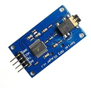
| − | This module is easy to interface since it only uses UART pins (Rx and Tx), excluding the Vcc and Ground. | + | This module is easy to interface since it only uses UART pins (Rx and Tx), excluding the Vcc and Ground. A voltage level of 3.3V was used to power the board, and was supplied from the SJ2 board. The MP3 decoder was connected to 2 of SJ2's port 2 pins that have UART functionality. The baud rate required for communication is 9600 bps. This decoder also contains an audio jack to connect headphones or speakers. |
[[File:MP3_Decoder_Schematic.JPG|700px|thumb|center|Connection diagram of MP3 decoder to SJ2 board.]] | [[File:MP3_Decoder_Schematic.JPG|700px|thumb|center|Connection diagram of MP3 decoder to SJ2 board.]] | ||
| − | |||
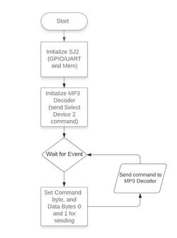
==== Software Design ==== | ==== Software Design ==== | ||
| Line 809: | Line 1,001: | ||
[[File:MP3DecoderFlowChart.JPG|center|250px|thumb|MP3 Decoder flowchart]] | [[File:MP3DecoderFlowChart.JPG|center|250px|thumb|MP3 Decoder flowchart]] | ||
| + | |||
| + | Below, are snippets of the code used to setup the commands and send them. A command we used in our Treasure Diver project was to cycle through music in one folder. The function that send this command is called mp3_decoder__Cycle_play_folder(). Within commands, there are two function calls for setting up the packet (set_command_and_data()) and the other for sending the packet over UART (send_command()). For more information on the command packet, see the implementation section. | ||
| + | |||
| + | <pre> | ||
| + | void mp3_decoder__cycle_play_folder(uint8_t folder) { | ||
| + | set_command_and_data(mp3_decoder__cycle_folder, folder, no_data); | ||
| + | send_command(); | ||
| + | } | ||
| + | |||
| + | static void set_command_and_data(uint8_t command, uint8_t data0, uint8_t data1) { | ||
| + | command_message.decoder_command_byte.command_byte = command; | ||
| + | command_message.decoder_command_byte.data_byte0 = data0; | ||
| + | command_message.decoder_command_byte.data_byte1 = data1; | ||
| + | } | ||
| + | |||
| + | static void send_command(void) { | ||
| + | uint8_t i = 0; | ||
| + | while (i < 8) { | ||
| + | if (uart__polled_put(uart, command_message.decoder_command.bytes[i])) { | ||
| + | i++; | ||
| + | } | ||
| + | } | ||
| + | } | ||
| + | </pre> | ||
==== Implementation ==== | ==== Implementation ==== | ||
| Line 836: | Line 1,052: | ||
=== Bluetooth Interface === | === Bluetooth Interface === | ||
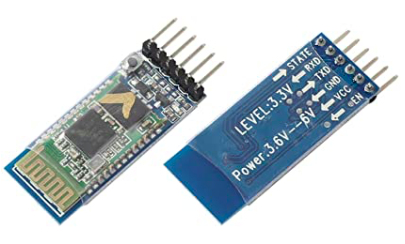
| − | + | We used two HC-05 bluetooth modules for our project, one on the game pad controller board acting as master, and one on the matrix controller board acting as slave. The master bluetooth module transmitted joystick, accelerometer, and button press data to the slave bluetooth module. The slave bluetooth module transmitted controller input type data (accelerometer or joystick) to the master bluetooth module. | |
| + | |||
| + | We decided to go with the HC-05 variant of bluetooth modules because they are easy to setup, easy to use, and extremely reliable to the point that we didn't have a single issue with either of these modules. We liked the configurability of the HC-05 because it could be adapted to suit the needs of different projects through its many configuration options. Configuration was done by using AT commands to configure one bluetooth module as master, the other as slave, and to set the UART baud rate to 38400. Additionally, we chose to "lock" the master bluetooth module to its corresponding slave module to prevent it from pairing with another bluetooth device in range. | ||
| + | |||
| + | [[File:HC-05_Bluetooth_Module.png|700px|thumb|center|HC-05 Bluetooth Module]] | ||
==== Hardware Design ==== | ==== Hardware Design ==== | ||
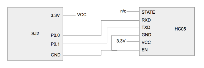
| − | + | The HC-05 modules were connected to each board using the same SJ2 pin numbers (UART peripheral #3 on P0.0 and P0.1). Each HC-05 communicates with its respective SJ2 board through a UART interface. The game pad controller SJ2 board processes the button press and joystick signals and sends them to it's bluetooth module via UART. This bluetooth module then send this data to the other bluetooth module. The received button press and joystick signals are then sent to the matrix controller SJ2 board via UART in order for them to be processed. The same logic applies for sending controller input type data (joystick or accelerometer) from the matrix controller SJ2 board to the game pad controller SJ2 board. | |
| + | |||
| + | [[File:HC-05_Bluetooth_Module_to_SJ2_Connections.png|700px|thumb|center|HC-05 Bluetooth Module to SJ2 Connections]] | ||
==== Software Design ==== | ==== Software Design ==== | ||
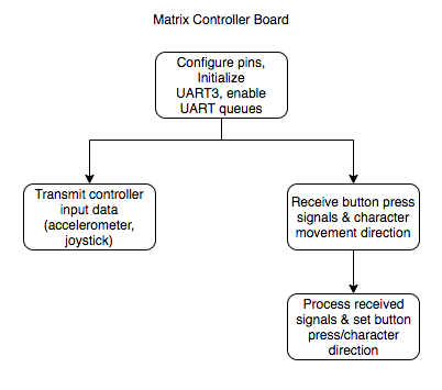
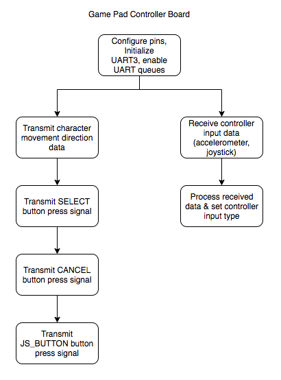
| − | + | Before the tasks are started on each board, the UART3 peripheral is initialized and the SJ2's P0.0 and P0.1 pins are set to UART pin functions. Each SJ2 board has a "transmit to bluetooth" and "receive from bluetooth" task in order to constantly transmit and receive commands to/from its connected bluetooth module. The matrix controller board's transmit task transmits the controller input type data that the user has selected in the options menu. The matrix controller's receive task receives all data sent from the game pad controller's bluetooth device and passes the received data into a handler function. The handler determines what string was received and then calls our controls API to set the proper button presses and character movement. | |
| + | |||
| + | [[File:Matrix_Controller_Board_Bluetooth_Flow_Chart.png|700px|thumb|center|Matrix Controller Board Bluetooth Software Flow Chart]] | ||
| + | |||
| + | The game pad controller board's transmit task transmits the joystick/accelerometer direction data, and button press data. The transmit task has a function that calls transmit functions for each type of data to be sent; select button, cancel button, joystick button, and accelerometer/joystick direction data. The game pad controller's receive task receives all data sent from the matrix controller's bluetooth device and passes the received data into a handler function. The handler determines what string was received and then calls our controls API to set the proper controller input type. | ||
| + | |||
| + | [[File:Game_Pad_Controller_Board_Bluetooth_Flow_Chart.png|700px|thumb|center|Game Pad Controller Board Bluetooth Software Flow Chart]] | ||
==== Implementation ==== | ==== Implementation ==== | ||
| − | ( | + | The bluetooth driver implementation consisted of initializing the UART3 interface (with transmit and receive queues enabled) between the SJ2 and bluetooth module, and comparing the string received from the bluetooth module with several pre-defined strings in order to determine what command was actually received. For example, if the joystick is tilted upward, the game pad's bluetooth module sends the string "N\r\n", which is the exact string that the matrix controller's bluetooth module receives. This received string is compared against all of the commands we have defined to find a match. In this case, a match will be found with pre-defined string "N\r\n", and so the "set character movement direction to N" function is called. |
| + | |||
| + | The matrix controller's received strings are processed by the handler function below that compares the received string against every command that we have defined. | ||
| + | |||
| + | '''Matrix Controller Received Bluetooth Commands''' | ||
| + | * SELECT - select button on the game pad was pressed | ||
| + | * CANCEL - cancel button on the game pad was pressed | ||
| + | * CENTERED - character shouldn't move | ||
| + | * N - move character up (N direction) | ||
| + | * NE - move character NE (not used) | ||
| + | * E - move character right (E direction) | ||
| + | * SE - move character SE (not used) | ||
| + | * S - move character down (S direction) | ||
| + | * SW - move character SW (not used) | ||
| + | * W - move character left (W direction) | ||
| + | * NW - move character NW (not used) | ||
| + | |||
| + | <pre> | ||
| + | void bluetooth_handler__process_received_bluetooth_command(char string[]) { | ||
| + | if (strcmp(string, "SELECT\r\n") == 0) { | ||
| + | controls__set_SELECT_button_pressed(true); | ||
| + | } else { | ||
| + | controls__set_SELECT_button_pressed(false); | ||
| + | } | ||
| + | |||
| + | if (strcmp(string, "CANCEL\r\n") == 0) { | ||
| + | controls__set_CANCEL_button_pressed(true); | ||
| + | } else { | ||
| + | controls__set_CANCEL_button_pressed(false); | ||
| + | } | ||
| + | |||
| + | if (strcmp(string, "CENTERED\r\n") == 0) { | ||
| + | controls__set_joystick_direction(CENTERED); | ||
| + | } else if (strcmp(string, "N\r\n") == 0) { | ||
| + | controls__set_joystick_direction(N); | ||
| + | } else if (strcmp(string, "NE\r\n") == 0) { | ||
| + | controls__set_joystick_direction(NE); | ||
| + | } else if (strcmp(string, "E\r\n") == 0) { | ||
| + | controls__set_joystick_direction(E); | ||
| + | } else if (strcmp(string, "SE\r\n") == 0) { | ||
| + | controls__set_joystick_direction(SE); | ||
| + | } else if (strcmp(string, "S\r\n") == 0) { | ||
| + | controls__set_joystick_direction(S); | ||
| + | } else if (strcmp(string, "SW\r\n") == 0) { | ||
| + | controls__set_joystick_direction(SW); | ||
| + | } else if (strcmp(string, "W\r\n") == 0) { | ||
| + | controls__set_joystick_direction(W); | ||
| + | } else if (strcmp(string, "NW\r\n") == 0) { | ||
| + | controls__set_joystick_direction(NW); | ||
| + | } | ||
| + | } | ||
| + | </pre> | ||
| + | |||
| + | The matrix controller's transmit strings are sent by the transmit function below. This function is called in a task to continuously transmit this data to the game pad controller board. | ||
| + | |||
| + | <pre> | ||
| + | void bluetooth_driver__transmit_controller_input_type_data(void) { | ||
| + | controller_t controller_input = controls__get_controller_input_type(); | ||
| + | char data_to_send[20]; | ||
| + | |||
| + | switch (controller_input) { | ||
| + | case JOYSTICK: | ||
| + | sprintf(data_to_send, "JOYSTICK\r\n"); | ||
| + | break; | ||
| + | case ACCELEROMETER: | ||
| + | sprintf(data_to_send, "ACCELEROMETER\r\n"); | ||
| + | break; | ||
| + | default: | ||
| + | sprintf(data_to_send, "JOYSTICK\r\n"); | ||
| + | break; | ||
| + | } | ||
| + | |||
| + | int buffer_index = 0; | ||
| + | while (data_to_send[buffer_index] != '\0') { | ||
| + | uart__put(UART__3, data_to_send[buffer_index], 0); | ||
| + | buffer_index++; | ||
| + | } | ||
| + | } | ||
| + | </pre> | ||
| + | |||
| + | The game pad controller's received strings are processed by the handler function below that compares the received string against every command that we have defined. | ||
| + | |||
| + | '''Game Pad Controller Received Bluetooth Commands''' | ||
| + | * JOYSTICK - set the controller input type to joystick | ||
| + | * ACCELEROMETER - set the controller input type to accelerometer | ||
| + | |||
| + | <pre> | ||
| + | void bluetooth_handler__process_received_bluetooth_command(char string[]) { | ||
| + | if (strcmp(string, "JOYSTICK\r\n") == 0) { | ||
| + | controls__set_controller_input_type(JOYSTICK); | ||
| + | } else if (strcmp(string, "ACCELEROMETER\r\n") == 0) { | ||
| + | controls__set_controller_input_type(ACCELEROMETER); | ||
| + | } | ||
| + | } | ||
| + | </pre> | ||
| + | |||
| + | The game pad controller's transmit strings are sent by the transmit functions below. These functions are called in a task to continuously transmit this data to the matrix controller board. For simplicity, only the select button's transmit function is shown below but the transmit function looks the same for all other button presses (the word "select" is just replaced with the other button press's signal name). | ||
| + | |||
| + | <pre> | ||
| + | static void bluetooth_driver__transmit_SELECT_button_data(void) { | ||
| + | char data_to_send[20]; | ||
| + | sprintf(data_to_send, "SELECT\r\n"); | ||
| + | |||
| + | int buffer_index = 0; | ||
| + | while (data_to_send[buffer_index] != '\0') { | ||
| + | uart__put(UART__3, data_to_send[buffer_index], 0); | ||
| + | buffer_index++; | ||
| + | } | ||
| + | |||
| + | controls__set_SELECT_button_pressed(false); | ||
| + | } | ||
| + | |||
| + | static void bluetooth_driver__transmit_joystick_data(void) { | ||
| + | joystick_direction_t joystick_direction = controls__get_joystick_direction(); | ||
| + | char data_to_send[20]; | ||
| + | |||
| + | switch (joystick_direction) { | ||
| + | case CENTERED: | ||
| + | sprintf(data_to_send, "CENTERED\r\n"); | ||
| + | break; | ||
| + | case N: | ||
| + | sprintf(data_to_send, "N\r\n"); | ||
| + | break; | ||
| + | case NE: | ||
| + | sprintf(data_to_send, "NE\r\n"); | ||
| + | break; | ||
| + | case E: | ||
| + | sprintf(data_to_send, "E\r\n"); | ||
| + | break; | ||
| + | case SE: | ||
| + | sprintf(data_to_send, "SE\r\n"); | ||
| + | break; | ||
| + | case S: | ||
| + | sprintf(data_to_send, "S\r\n"); | ||
| + | break; | ||
| + | case SW: | ||
| + | sprintf(data_to_send, "SW\r\n"); | ||
| + | break; | ||
| + | case W: | ||
| + | sprintf(data_to_send, "W\r\n"); | ||
| + | break; | ||
| + | case NW: | ||
| + | sprintf(data_to_send, "NW\r\n"); | ||
| + | break; | ||
| + | default: | ||
| + | sprintf(data_to_send, "CENTERED\r\n"); | ||
| + | break; | ||
| + | } | ||
| + | |||
| + | int buffer_index = 0; | ||
| + | while (data_to_send[buffer_index] != '\0') { | ||
| + | uart__put(UART__3, data_to_send[buffer_index], 0); | ||
| + | buffer_index++; | ||
| + | } | ||
| + | |||
| + | controls__set_joystick_direction(CENTERED); | ||
| + | } | ||
| + | </pre> | ||
=== Game Pad Controller === | === Game Pad Controller === | ||
| − | |||
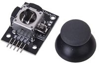
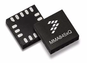
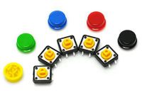
The main components in Game Pad controller are a joystick, accelerometer, two buttons, and bluetooth. The controller is used to send commands and control Steve (the main character) in Treasure Diver, along with navigation of the menus, with the joystick or the SJ2's on-board accelerometer (user's choice). With bluetooth on the game pad, the controller is wireless. | The main components in Game Pad controller are a joystick, accelerometer, two buttons, and bluetooth. The controller is used to send commands and control Steve (the main character) in Treasure Diver, along with navigation of the menus, with the joystick or the SJ2's on-board accelerometer (user's choice). With bluetooth on the game pad, the controller is wireless. | ||
| + | {| style="margin-left: auto; margin-right: auto; border: none;" | ||
[[File:Joystick.JPG|200px|thumb|center|Amazon image of the joystick]] | [[File:Joystick.JPG|200px|thumb|center|Amazon image of the joystick]] | ||
[[File:CmpE244 F19 T4 Accelerometer.png|200px|thumb|center|On-board accelerometer]] | [[File:CmpE244 F19 T4 Accelerometer.png|200px|thumb|center|On-board accelerometer]] | ||
| + | [[File:PushButtons.JPG|200px|thumb|center|Push buttons used for the select and cancel buttons of the Game Pad]] | ||
| + | |} | ||
==== Hardware Design ==== | ==== Hardware Design ==== | ||
| − | + | The setup of the game pad's hardware was very simple. The two push buttons (cancel and select) use the same configuration. Both are use a pull up resistor when open (not pressed) and short to ground when pressed. This was done to improve the signal and make sure the SJ2 gpio would read high or low. | |
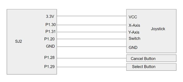
| + | The accelerometer was easy to initialize since there was already existing API. So, all it required was was reading and properly handling the data to send the command to the master board to control Stave. The joystick require initializing. Although, the input of both was different, the output was essentially the same. The accelerometer and joystick both had analog outputs which would then be read by an analog to digital converter (ADC). | ||
[[File:GamePadSchematic.JPG|700px|thumb|center|Schematic of Game Pad controller]] | [[File:GamePadSchematic.JPG|700px|thumb|center|Schematic of Game Pad controller]] | ||
| + | The outputs would represent the X and Y positions of both devices. The analog stick was also a button that could be pressed, but it was not implemented in the project, due to time constraints. | ||
==== Software Design ==== | ==== Software Design ==== | ||
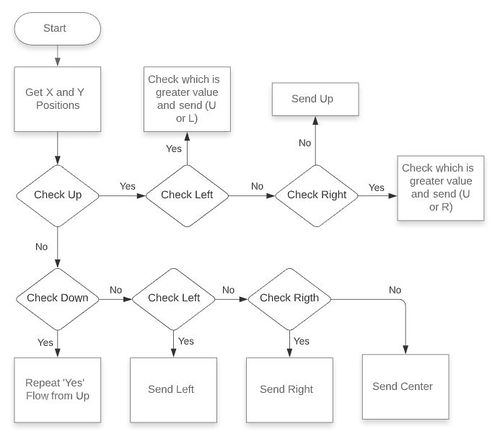
| − | + | When the software is sending commands, it gets the ADC values and analyzes which direction the accelerometer or joystick is indicating. The flow primarily checks up/down and if it is one of these, then L/R is checked. If one of these is true, the software checks which direction is a greater magnitude. This approach is used for both the accelerometer and joystick. | |
| + | [[File:GamePadFlowChart.JPG|500px|thumb|center|HC-05 Bluetooth Module to SJ2 Connections]] | ||
| + | As an example for more clarity, if DOWN is true and RIGHT is true, we then check which directions has a greater value. If the joystick/accelerometer is leaning more in the DOWN direction, then the game pad will send this direction to the Master board. | ||
| + | |||
| + | <pre> | ||
| + | joystick_direction_t joystick_controls__get_joystick_direction(void) { | ||
| + | joystick_direction_t joysticks_direction = CENTERED; | ||
| + | const joystick_s current_position = get_joystick_position(); | ||
| + | |||
| + | if (check_up(current_position.y)) { | ||
| + | if (check_left(current_position.x)) { | ||
| + | if (current_position.y < (-1 * current_position.x)) { | ||
| + | joysticks_direction = W; | ||
| + | } else { | ||
| + | joysticks_direction = N; | ||
| + | } | ||
| + | } else if (check_right(current_position.x)) { | ||
| + | if (current_position.y < current_position.x) { | ||
| + | joysticks_direction = E; | ||
| + | } else { | ||
| + | joysticks_direction = N; | ||
| + | } | ||
| + | } else { | ||
| + | joysticks_direction = N; | ||
| + | } | ||
| + | } else if (check_down(current_position.y)) { | ||
| + | if (check_left(current_position.x)) { | ||
| + | if ((-1 * current_position.y) < (-1 * current_position.x)) { | ||
| + | joysticks_direction = W; | ||
| + | } else { | ||
| + | joysticks_direction = S; | ||
| + | } | ||
| + | } else if (check_right(current_position.x)) { | ||
| + | if ((-1 * current_position.y) < current_position.x) { | ||
| + | joysticks_direction = E; | ||
| + | } else { | ||
| + | joysticks_direction = S; | ||
| + | } | ||
| + | } else { | ||
| + | joysticks_direction = S; | ||
| + | } | ||
| + | } else { | ||
| + | if (check_left(current_position.x)) { | ||
| + | joysticks_direction = W; | ||
| + | } else if (check_right(current_position.x)) { | ||
| + | joysticks_direction = E; | ||
| + | } | ||
| + | } | ||
| + | </pre> | ||
==== Implementation ==== | ==== Implementation ==== | ||
| − | + | The axis of the joystick did not match the X and Y of our board positioning. To "rotate" the axis, the function swap_and_shift_axis() was created. The swap really occurs if the ADC port of X-axis is passed to the function so it can return a value to the game pad's Y-axis. The purpose of the shift is to make it easier when checking magnitudes of two different directions, as explained in the previous section. | |
| + | <pre> | ||
| + | static uint16_t swap_and_shift_axis(adc_channel_e axis) { | ||
| + | const uint16_t shift_value = 2250; | ||
| + | int16_t axis_value = adc__get_channel_reading_w_burst_mode(axis) - shift_value; | ||
| + | |||
| + | return axis_value; | ||
| + | } | ||
| + | |||
| + | static joystick_s get_joystick_position(void) { | ||
| + | static joystick_s joystick_pos; | ||
| + | |||
| + | joystick_pos.x = swap_and_shift_axis(Y_AXIS); | ||
| + | joystick_pos.y = swap_and_shift_axis(X_AXIS); | ||
| + | |||
| + | return joystick_pos; | ||
| + | } | ||
| + | </pre> | ||
== Technical Challenges == | == Technical Challenges == | ||
| − | |||
| − | |||
| − | |||
| − | |||
=== CAD Enclosures Design === | === CAD Enclosures Design === | ||
* When we received the 3D printed enclosures, some of the holes were smaller than designed. This can happen in FDM printing because plastic is melted and placed layer by layer, which is only accurate to a certain thickness and height. In order to enlarge the holes, a needle file was used to file down the openings until the hole was big enough. | * When we received the 3D printed enclosures, some of the holes were smaller than designed. This can happen in FDM printing because plastic is melted and placed layer by layer, which is only accurate to a certain thickness and height. In order to enlarge the holes, a needle file was used to file down the openings until the hole was big enough. | ||
| − | * Due to the COVID pandemic, we were unable to access the free 3D printing services offered by SJSU and so we had to pay to get our enclosures printed. Our original design was extremely costly and so the enclosures had to be redesigned twice in order to bring the cost down to an affordable amount. All the redesigning we had to do took a lot of time away from the other aspects of our project and the resulting enclosures were not as fancy as we originally planned, but it was all we could afford | + | * Due to the COVID pandemic, we were unable to access the free 3D printing services offered by SJSU and so we had to pay to get our enclosures printed. Our original design was extremely costly and so the enclosures had to be redesigned twice in order to bring the cost down to an affordable amount. All the redesigning we had to do took a lot of time away from the other aspects of our project and the resulting enclosures were not as fancy as we originally planned, but it was all we could afford. |
| − | |||
=== PCB Design === | === PCB Design === | ||
| − | * Our first design of the matrix controller PCB had incorrect pin spacing for the led matrix pins because we accidentally used the wrong footprint. Unfortunately, we didn't notice this until after we had placed the PCB order and so we had to oder a second matrix controller PCB that had the correct matrix pin spacing. Fortunately, we noticed this before our order shipped and so we were able to add the corrected PCB design to our order without any additional delays | + | * Our first design of the matrix controller PCB had incorrect pin spacing for the led matrix pins because we accidentally used the wrong footprint. Unfortunately, we didn't notice this until after we had placed the PCB order and so we had to oder a second matrix controller PCB that had the correct matrix pin spacing. Fortunately, we noticed this before our order shipped and so we were able to add the corrected PCB design to our order without any additional delays. |
| − | |||
| − | |||
=== LED Matrix === | === LED Matrix === | ||
* When testing the game, we observed that if the character hit an obstacle and the joystick direction moving the character towards the obstacle was held for over a second or so, the game character would actually start to move into the obstacle. We realized that this was because the collision detection wasn't updating quick enough, and so we changed the collision detection's task priority from low to high. Using high priority for the collision detection task solved this problem. | * When testing the game, we observed that if the character hit an obstacle and the joystick direction moving the character towards the obstacle was held for over a second or so, the game character would actually start to move into the obstacle. We realized that this was because the collision detection wasn't updating quick enough, and so we changed the collision detection's task priority from low to high. Using high priority for the collision detection task solved this problem. | ||
| − | * | + | * Ghosting was some time an issue in which an after image of an obstacle or image would sometimes linger on screen. This may happen because the GND pins on the Sjtwo board are not soldered correctly. After switching over to a PCB to connect the LED and board these issues stopped happening. |
| − | |||
=== MP3 Decoder === | === MP3 Decoder === | ||
* The datasheet lacks some information and clarity on initializing the module and with some of the commands. When first using it, non of the commands appeared to work or have any effect. The issue was resolved after sending the command to select a device, which was not explicitly stated in the datasheet. Once this command is first sent, the MP3 decoder now begins accepting commands. | * The datasheet lacks some information and clarity on initializing the module and with some of the commands. When first using it, non of the commands appeared to work or have any effect. The issue was resolved after sending the command to select a device, which was not explicitly stated in the datasheet. Once this command is first sent, the MP3 decoder now begins accepting commands. | ||
| − | |||
| − | |||
=== Bluetooth Interface === | === Bluetooth Interface === | ||
| − | * | + | * During testing, we realized that once a bluetooth command was sent, it would repeatedly send instead of just being sent once. For example, when the select button was pressed on the game pad, the select command would continuously send even though the button had been released and was no longer pressed. This is just how the bluetooth device works and so we had to make some modifications in our bluetooth handler code to accommodate this. In order to solve the button press data re-sending issue, we set button press to false immediately after receiving a button press command. In order to solve the joystick/accelerometer data re-sending issue, we defined a default state (CENTERED) which means no character movement, so it didn't matter that the centered command was being sent continuously. |
| − | |||
| − | |||
=== Game Pad Controller === | === Game Pad Controller === | ||
| − | * | + | * Originally, thresholds for each direction were checked without comparing to another, and it would cause the character to go in a direction that was not intended or not move. When adding comparisons of magnitudes, character control greatly improved. |
| − | |||
| − | |||
== Advice for Future Students == | == Advice for Future Students == | ||
| Line 909: | Line 1,349: | ||
=== CAD Enclosures Design === | === CAD Enclosures Design === | ||
| − | * | + | * If the 3D printing services offered by the library and SCE club aren't available (due to COVID pandemic), then use [https://jinxbot.com Jinxbot]. They are the cheapest local option we found and offer shipping or you can pick up locally in Mountain View. They print extremely quickly, we got our prints 3 days after ordering. |
| − | |||
| − | |||
=== PCB Design === | === PCB Design === | ||
| Line 918: | Line 1,356: | ||
* Order your PCBs from JLCPCB (integrated into EasyEDA). You'll get them in 1 week. | * Order your PCBs from JLCPCB (integrated into EasyEDA). You'll get them in 1 week. | ||
* In EasyEDA, may sure you check the connections for each footprint you're using. Sometimes the footprint's pinout won't exactly match your schematic. | * In EasyEDA, may sure you check the connections for each footprint you're using. Sometimes the footprint's pinout won't exactly match your schematic. | ||
| − | * | + | * Create a google sheet for all team members to fill out with the SJ2 pins they are using for there device/task. It will help prevent multiple people from using the same pins that may cause confusion down the road and include the voltage required for their device. This will help simplify PCB design when referencing this document. Also include an image of the SJ2 board's pins for referencing while filling out the sheet. |
=== LED Matrix === | === LED Matrix === | ||
| − | * | + | * '''START EARLY AND FINISH THE LED DRIVER ASAP''' The longer you take to implement the driver, the more time you have to wait before you can do any actual game development. You will really start feeling it towards the last week where you want to add polish to your game but you no longer have time. You do not want to catch yourself saying "Just one more week". |
| − | * | + | |
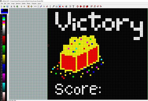
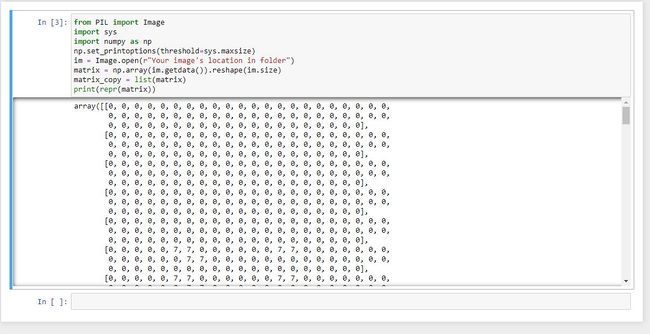
| − | * | + | * For the more artistically gifted amongst you, GIMP and MtPaint (open source) are fantastic resources for planning out levels and designing images. For example you can draw out your image and then using a python script or other image processing software you can get 2d array representation of your image that you can place your code. This is going to be much easier than writing entire screens out by hand: |
| + | |||
| + | {| style="margin-left: auto; margin-right: auto; border: none;" | ||
| + | |[[File:MTPaint.jpg|500px|thumb|center| Draw Your images...]] | ||
| + | |[[File:array_conversion.jpg|650px|thumb|center| And Put Them in a form you can use in Code]] | ||
| + | |} | ||
| + | * Additionally, there are other software tools that can be used to design these screens or other objects for the LED matrix. Pixelable was an app used on the iPad, which allowed exporting the created images and could be opened in MtPaint, if needed. | ||
=== MP3 Decoder === | === MP3 Decoder === | ||
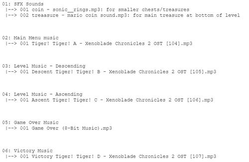
| − | * | + | * We were not successful in getting the single cycle command to work for the MP3 decoder so that we would play a specific song in a folder in have it on repeat. So, instead of having SFX, Title/Menu music and level music in there own folders, I created a folder for each song (shown in image below). This allowed us to use the command that cycles all the music in one folder, essentially having the desired result. |
| − | + | [[File:SDfolderStructure.JPG|500px|thumb|center|Folder structure in SD card]] | |
| − | |||
=== Bluetooth Interface === | === Bluetooth Interface === | ||
| − | * | + | * Using [https://play.google.com/store/apps/details?id=project.bluetoothterminal&hl=en_US&gl=US this] HC-05 bluetooth terminal app (also linked in reference section) will really help when you're trying to get your bluetooth modules configured initially and during testing/debugging of your bluetooth interface. We were also able to use this app as a game pad to control our character's movement on the LED matrix and send button press signals, which was useful for the members of our team who didn't have a second SJ2 board. |
| − | |||
| − | |||
=== Game Pad Controller === | === Game Pad Controller === | ||
| − | * | + | * Create a function that prints the X and Y values of the accelerometer and/or joystick. It will be useful for debugging and further understanding the device. |
| − | |||
| − | |||
| − | |||
| − | |||
| − | |||
| − | |||
| − | |||
| − | |||
== Conclusion == | == Conclusion == | ||
| − | + | We really enjoyed the process of making this project and have learned so much. Our driver writing skills were honed through writing drivers for each module we used (LED matrix, MP3 decoder, Bluetooth, etc.), our understanding of FreeRTOS API has increased, and we gained some basic game and graphics development skills through the LED matrix aspects of this project. Throughout the entire duration of this project, we encountered numerous challenges such as difficulty getting the LED matrix driver up and running, figuring out how to implement collision detection with so many game objects, writing and maintaining our complex game logic state machine and much more. Additionally, we experienced challenges due to the COVID pandemic particularly for the 3D printing aspects of this project, as we did not have access to SJSU's 3D printing services for students and had to pay a premium price to get our enclosures printed. Due to time constraints, there were parts of our project that had to be changed or couldn't be implemented and so future improvements that we'd like to add would be a fancier matrix enclosure, auto-scrolling during gameplay, adding the in-between cardinal directions for character movement (NE, NW, SE, SW), and assigning a functionality to the switch button on our gamepad's joystick. Despite the challenges and setbacks we faced, we were able to overcome every single one of them in order to build a finished product that we are all proud of. | |
=== Project Video === | === Project Video === | ||
| Line 958: | Line 1,391: | ||
=== Project Source Code === | === Project Source Code === | ||
* [https://gitlab.com/deharo27/treasure-diver GitLab Code Link] | * [https://gitlab.com/deharo27/treasure-diver GitLab Code Link] | ||
| + | |||
| + | === Acknowledgements === | ||
| + | We would like to thank our professor Preet and all the ISA's for putting together such a great class and for setting high expectations. This always inspired us to go above and beyond. | ||
== References == | == References == | ||
| − | |||
| − | |||
| − | |||
| − | |||
| − | |||
| − | |||
LED Matrix | LED Matrix | ||
| − | * | + | * [https://www.sparkfun.com/news/2650 Everything You Didn't Want to Know About RGB Matrix Panels] |
| − | * ... | + | * [http://mtpaint.sourceforge.net/ Mtpaint Source & Documentation] |
| + | * [https://learn.adafruit.com/32x16-32x32-rgb-led-matrix/new-wiring AdaFruit walk Through for LED Matrix Wiring] | ||
MP3 Decoder | MP3 Decoder | ||
| − | * | + | * [https://github.com/cefaloide/ArduinoSerialMP3Player MP3 Decoder Datasheets] |
| − | |||
HC-05 Bluetooth Modules | HC-05 Bluetooth Modules | ||
| − | * | + | * [https://www.teachmemicro.com/hc-05-bluetooth-command-list/ HC-05 Bluetooth AT Commands] |
| − | * ... | + | * [https://howtomechatronics.com/tutorials/arduino/how-to-configure-pair-two-hc-05-bluetooth-module-master-slave-commands/ HC-05 Bluetooth Configuration & Pairing] |
| + | * [https://play.google.com/store/apps/details?id=project.bluetoothterminal&hl=en_US&gl=US HC-05 Bluetooth Terminal App for Testing] | ||
| + | |||
| + | 3D Printing | ||
| + | * [https://www.cati.com/blog/2018/05/3d-cad-design-3d-printing-tips-tricks-techniques-part-1/ Design Tips] | ||
| + | * [https://www.3dhubs.com/knowledge-base/key-design-considerations-3d-printing/ Design Limitations] | ||
| + | * [https://jinxbot.com Local 3D Printing Shop] | ||
Latest revision as of 00:05, 31 May 2021
Contents
- 1 Treasure Diver
- 2 Abstract
- 3 Objectives
- 4 Introduction
- 5 Schedule
- 6 Parts Lists & Cost
- 7 Design & Implementation
- 8 Technical Challenges
- 9 Advice for Future Students
- 10 Conclusion
- 11 References
Treasure Diver
Abstract
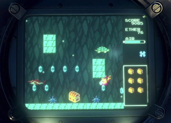
Treasure Diver is a single player game in which the player descends into the watery depths on the hunt for treasure. The player must dodge obstacles and enemy creatures all while collecting treasure along the way. While descending, the player is able to attack enemies at a range which in turn increases the player's score. When they reach the bottom of the level, they can collect the large treasure chest called the Motherlode. Once the Motherlode is collected, they have to ascend the cavern and make it out before running out of air. Hitting an enemy causes the player to lose air, a treasure chest, and their score to decrease. When their air hits zero, it’s game over. At the end of a level the player is given their score based on treasure collected, and the amount of enemies destroyed, and can progress to the next level.
Objectives
The main objective of this project was to create the treasure diver video game displayed on an RGB LED matrix, one SJ2 board as a graphics processor/matrix controller, and another SJ2 board as a game pad controller. Other objectives are the following:
- Design custom PCBs for both the game pad and matrix controller SJ2 boards.
- Design custom 3D printed enclosures for both the matrix and game pad controller.
- Use the FreeRTOS Real-Time Operating System on both SJ2 boards.
- Use a wireless interface for communication between both SJ2 boards.
- Incorporate an acceleration sensor as one of the options to control the game character's movement.
- Add background music to the game to enhance gameplay experience.
Introduction
This project was divided into the following modules for each SJ2 board:
- Matrix Controller Board: The matrix controller board is responsible for displaying the graphics of the treasure diver game, controlling the treasure diver game logic, playing MP3 tracks based on the current game/menu screen, receiving character movement and button press signals over a bluetooth interface, and sending controller type (accelerometer or joystick) signals over a bluetooth interface.
- Game Pad Controller Board: The game pad controller board is responsible for processing input joystick, accelerometer and button press signals, controlling the treasure diver game controls logic, sending character movement and button press signals over a bluetooth interface, and receiving controller type (accelerometer or joystick) signals over a bluetooth interface.
How to Play Treasure Diver
The goal of the game is to descend to the bottom of each level, collect the Motherlode (big treasure chest), and make it all the way back to the top of the level before running out of air and with the highest score possible.
- Using the joystick or accelerometer controls (chosen in options menu) on the game pad controller, move the game character down to the bottom of each screen in each game level.
- Once the character reaches the bottom of a screen, the next screen of the level will appear.
- Avoid all the obstacles while descending, collect as many treasure chests and shoot as many enemies as possible to increase your score.
- You can shoot enemies by pressing the select button on the game pad controller (button on the left).
- Try not to get hit by any enemies! Doing so will cause you to lose a chest, some air, and your score will decrease. If you run out of air, you lose the game and will have to restart at the first level.
- Once you get to the last screen of the level, you must collect the big treasure chest at the bottom of the screen before you can start ascending. You get back half of your air when you collect this chest.
- Now that you've got the Motherlode, move the game character back up to the top of the first screen of the level before you run out of air!
- Once you reach the top of the first screen in the level, you will enter the next game level.
- Beat all levels in order to win the treasure diver game!
Team Members & Responsibilities
Treasure Diver GitLab
- LED Matrix Driver
- Matrix Graphics Development
- Game Logic Development
- Gameplay Mechanics Design
- Wiki Page Management
- Game Pad Controller
- MP3 Decoder Driver
- Matrix Graphics Development
- PCB Design
- GitLab Repo Management
Nicholas Kaiser GitLab LinkedIn
- HC05 Bluetooth Driver and Interface
- Matrix Collision Detection Development & Level Design
- CAD Enclosure Design
- PCB Design
- Wiki Page Management
Schedule
| Week # | Start Date | End Date | Tasks | Status |
|---|---|---|---|---|
| 1 | 9/27/2020 | 10/3/2020 |
|
|
| 2 | 10/4/2020 | 10/10/2020 |
|
|
| 3 | 10/11/2020 | 10/17/2020 |
|
|
| 4 | 10/18/2020 | 10/24/2020 |
|
|
| 5 | 10/25/2020 | 10/31/2020 |
|
|
| 6 | 11/1/2020 | 11/7/2020 |
|
|
| 7 | 11/8/2020 | 11/14/2020 |
|
|
| 8 | 11/15/2020 | 11/21/2020 |
|
|
| 9 | 11/22/2020 | 11/28/2020 |
|
|
| 10 | 11/29/2020 | 12/5/2020 |
|
|
| 11 | 12/6/2020 | 12/12/2020 |
|
|
| 12 | 12/13/2020 | 12/19/2020 |
|
|
Parts Lists & Cost
General Parts
| Item # | Part | Vendor | Qty | Cost |
|---|---|---|---|---|
| 1 | 64x64 RGB LED Matrix | Adafruit | 1 | $54.95 |
| 2 | SJTwo Boards | SJSU | 2 | $100.00 |
| 3 | HC-05 Bluetooth Boards | Amazon | 2 | $12.59 |
| 4 | MP3 Decoder/Player Board | Amazon | 1 | $7.39 |
| 5 | Speakers (with audio jack connection) | already had | 1 | $0 |
| 6 | Audio Jack Cable | already had | 1 | $0 |
| 7 | MicroSD Card & Adapter (32GB or smaller) | Amazon | 1 | $5.99 |
| 8 | Power Supply for LED Matrix (5V 5A) | Amazon | 1 | $14.99 |
| 9 | Tactile Push Buttons | Amazon | 2 | $7.98 |
| 10 | Analog Thumbstick | Amazon | 1 | $4.89 |
| 11 | Power Bank | already had | 1 | $0 |
| 12 | 6" USB to Micro-USB Cable | Amazon | 1 | $5.19 |
Game Pad PCB Components
| Item # | Part | Vendor | Qty | Cost |
|---|---|---|---|---|
| 1 | M3 Size (or smaller) Screws & Nuts | Amazon | 4 | $11.99 |
| 2 | 5-pin Right Angle Male Header | Amazon | 1 | $4.99 |
| 3 | 6-pin Right Angle Female Header | Amazon | 1 | $7.99 |
| 4 | 1K Through-Hole Resistors | Amazon | 2 | $5.69 |
| 5 | 2x20 Female Header | Amazon | 1 | $6.99 |
| 6 | Male Header Pins | Amazon | 16 | $4.99 |
Matrix Controller PCB Components
| Item # | Part | Vendor | Qty | Cost |
|---|---|---|---|---|
| 1 | 2.1mm DC Power Jack (Breadboard Compatible) | Adafruit | 1 | $0.95 |
| 2 | 2-pin Screw Terminal Block | Amazon | 1 | $5.99 |
| 3 | 2x20 Female Header | Amazon | 1 | $6.99 |
| 4 | 4-pin Right Angle Male Header | Amazon | 1 | $4.99 |
| 5 | 6-pin Right Angle Female Header | Amazon | 1 | $7.99 |
| 6 | Male Header Pins | Amazon | 20 | $4.99 |
| 7 | 2x8 Box Header | Amazon | 1 | $9.99 |
Matrix & Game Pad Enclosure Parts
| Item # | Part | Vendor | Qty | Cost |
|---|---|---|---|---|
| 1 | Game Pad and Matrix Enclosures | custom design | 1 | $153.34 |
| 2 | M3 Size (or smaller) Screws & PCB Standoffs | Amazon | 18 | $11.99 |
| 3 | #8-32 x 1/2 inch Machine Screws & Nuts | Home Depot | 8 | $1.18 |
| 4 | Male Header Pins | Amazon | 12 | $4.99 |
| 5 | Hot Glue Gun & Hot Glue Sticks | already had | 1 | $0 |
| 6 | 6" Slim Headphone Jack Extender (Male to Female) | Amazon | 1 | $6.99 |
| 7 | 6" DC Power Jack Extender (Male to Female) | Amazon | 1 | $9.89 |
| 8 | Velcro Straps (20mm wide) | Amazon | 2 | $6.59 |
Design & Implementation
PCB Design
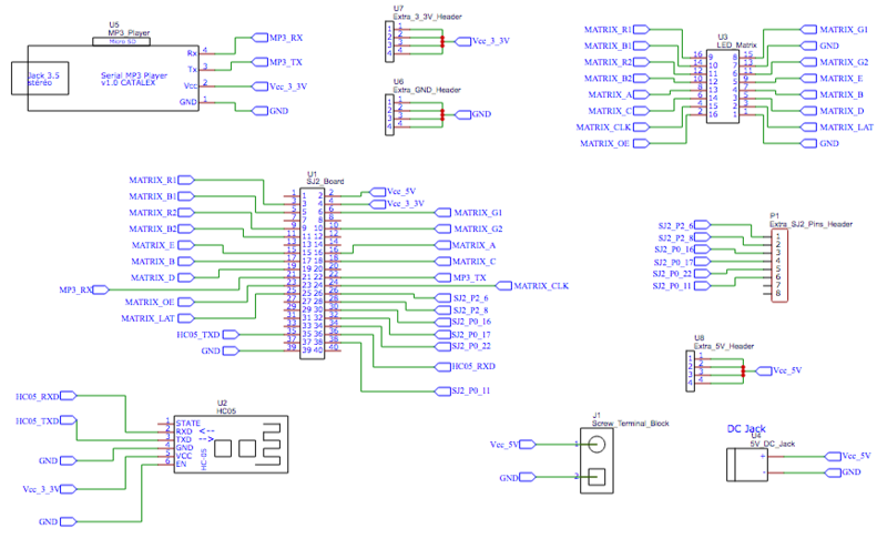
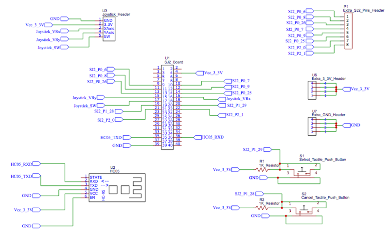
We chose EasyEDA as our PCB designing software since it is completely free to use with no trial period. Additionally, EasyEDA has a handy auto-routing feature, and the ability to create a PCB from a schematic. We designed two PCBs, one for our game pad controller and one for our matrix controller. First, we created separate schematics for both controllers that included all connections. We included extra GND, 3.3V, 5V, and SJ2 pins to accommodate any design changes down the road. We made these extra pins available as header pins on the PCBs.
Once our schematics were done and checked by each group member several times, we manually checked the footprint for each part we included in the schematic. Some of the parts we chose didn't have a footprint and so we had to search EasyEDA's library to find one. Also, the connections for several of the default footprints were incorrect for our design and had to be manually edited so that each pin corresponded to the correct solder pad. Once the footprints were all verified, we dragged and dropped the footprints onto the PCBs in precisely measured locations to ensure compatibility with our 3D printed enclosures. Next, EasyEDA's auto-routing feature was used and then manually checked to ensure proper connections.
We chose to order our PCBs from JLCPCB due to their fast manufacturing and shipping times, and reasonable PCB and shipping prices. As an added bonus, JLCPCB is integrated into EasyEDA, so ordering your PCB is extremely simple. Once we placed the order, our PCBs only took a week to arrive. We used a multimeter to continuity tested all the connections on the PCBs before hooking them up and didn't run into any incorrect connections during this testing.
Once the PCBs were verified, we soldered them up to integrate into our existing circuitry. The game pad PCB has precisely positioned holes so that the joystick can be screwed into the PCB, allowing for a very secure fit. The push buttons on the game pad PCBs were mounted on 10mm nylon standoffs and had header pins soldered to extend their pins. This was done in order to raise the height of the push buttons in order to match the height of the joystick.
CAD Enclosures Design
We used the FreeCAD software in order to design our custom enclosures for both the matrix and game pad. We decided to use FreeCAD because it is completely free with no trial period, and lots of documentation and help videos are available online. This software is not without bugs and inefficiencies but this was the only free option we could find that didn't have a trial period, design limitations, or size restrictions. FreeCAD also includes tons of user made workbenches that include pre-made designs for specific parts (screws, nuts, standoffs, etc) which can be useful and a time saver.
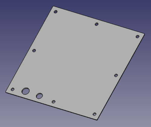
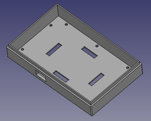
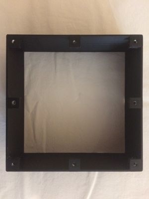
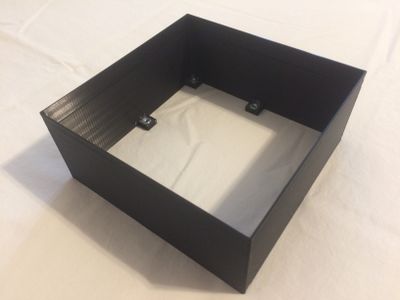
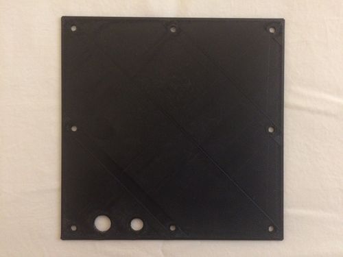
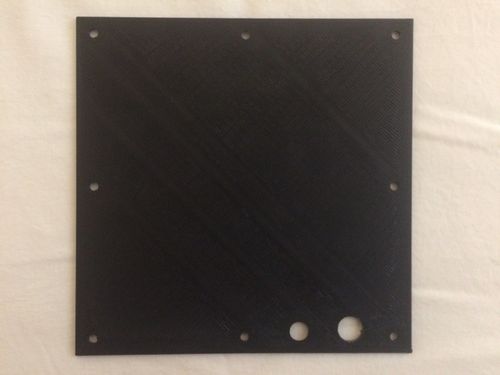
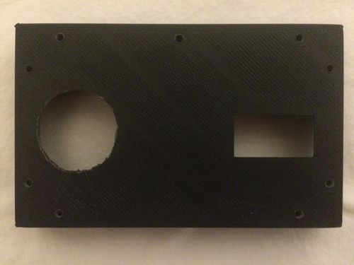
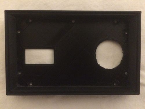
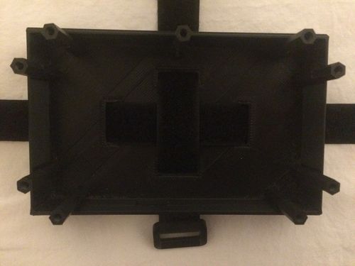
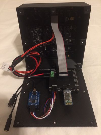
Our matrix enclosure design includes a casing slightly larger than the matrix. A lip was created on the inside for the matrix to rest on. Through taking precise measurements and using a thinner but more flexible outer wall, we were able to make the matrix "snap fit" into the enclosure. We designed tabs on the bottom of the matrix enclosure to place screw nuts into in order to make our enclosure screw shut. Our matrix enclosure design also included a back plate for all the circuitry components to be fastened to. The back plate has screw holes and cutouts for the power and audio cables.
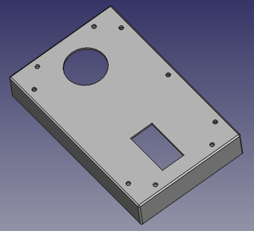
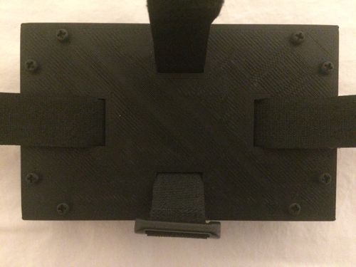
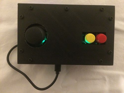
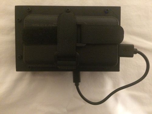
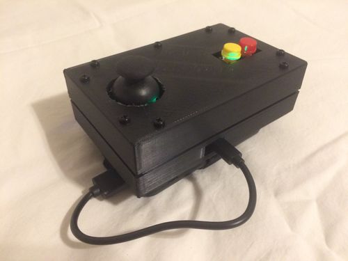
Our game pad enclosure design includes a top and bottom cover for the game pad controller circuitry to sit in. Through taking precise measurements, our game pad controller circuitry fits snugly into the enclosure and is held in place by the SJ2 board's micro-USB port sticking through the cutout in the enclosure's bottom cover. This allows for easy installation and removal which was helpful for debugging. The enclosure's top cover has cutouts for the joystick and two push buttons while the bottom cover has cutouts on its bottom face for velcro straps to secure the power source to the bottom of the game pad enclosure. We designed an inner lip (top cover) and an outer lip (bottom cover) so that the two covers would fit together securely. We designed matching screw hole cutouts for each cover so that the game pad enclosure could be screwed shut.
Getting our enclosures printed proved to be a challenge. Normally, the SJSU library offers free 3D Printing services to students and the SCE club offers free 3D printing services to members, but due to the COVID pandemic, SJSU and all of it's services were shutdown and so we had to explore other options. Online 3D Printing services were incredibly expensive so we chose a local place that printed our enclosures for about $155. Due to the limitations of FDM 3D printing, the screw hole and joystick cutouts on the game pad enclosure and the power jack cutout on the matrix enclosure had to be manually made larger using a needle file but this was the only post-printing modification that had to be made.
Assembly of the matrix enclosure included using hot glue to glue a screw nut into each tab so that screws could be threaded through the back plate to fasten it to the main body of the matrix enclosure. We chose a screw shut design because it would make assembly and disassembly easier during debugging. Assembly of the game pad enclosure included placing standoffs between the top and bottom covers so that screws could be threaded through each cover and into one end of the standoff to hold the game pad enclosure together. Velcro straps were threaded through the cutouts in the bottom cover to hold the power source securely in place. A short 6" USB to micro-USB cable was used to connect the power source to the SJ2 via the cutout in the side of the bottom cover.
The SJ2 board and MP3 decoder board are mounted on the matrix enclosure's back plate, and 6" power and audio cables are run through to the outside of the enclosure for easy plug in access. The game pad enclosure's SJ2 board sits in the bottom cover, and a 6" USB to micro-USB cable runs from the power supply and plugs into the SJ2 board by plugging in through the cutout in the bottom cover.
Gameplay
The matrix controller board has a total of 9 tasks running in order to transmit/receive bluetooth data, manage the LED matrix graphics, manage and update the game play, and play background music.
Matrix Controller Tasks
- Bluetooth Transmit - transmits controller type that the player selects in the options menu.
- Bluetooth Receive - receives the button presses and character movement direction data from the game pad.
- Update Board - updates the graphics displayed on the LED matrix.
- Draw Character - draws the character on the LED matrix based on the direction data received from the game pad.
- Collision Detection - calls our collision detection function which checks for all types of collision between game objects.
- Bullet Handler - draws and clears the bullet, and calls a function that checks for any collisions between the bullet and another game object.
- Character Status Handler - updates the character's "hurt" status, and decrements the air (health) bar.
- State Machine - calls our state machine function which manages our gameplay and screen transitions.
- Play Music - plays a specific MP3 track based on the current game state.
State Machine
A State Machine was developed to control the flow of the gameplay to both synchronize the games various Tasks but also give the player an enjoyable User Interface in between levels.
The main states of the game are:
- The title screen which lets people start the game or go to the options menu
- The option screen which lets users pick the volume level of the game or pick the control type they want to play with.
- The four screens which compromise a level
- The Victory Screen if the player happens to make it out of the level with the big chest
- The Game Over Screen which shows up if the player dies
As the player moves between States, various bool flags are checked based on various factors to see if the Player should be allowed to move on to the next screen.
Software Design
From this State Machine a Player begins in the TITLE State. From there they can move an on screen cursor using the Joystick Controls and select button to start the game or go to OPTIONS. From OPTIONS the player can also move the cursor to adjust volume, set the controls to motion controls or use the cancel button to return to TITLE. If start Game is selected then initial parameters for the Game are set and the task that draws and controls the Character is given the flag to turn on, SCREEN1 is then jumped to. Screen1 is where the game starts properly; within it the levels are drawn which include the enemies, obstacles, chests, and UI elements. The music that played on the TITLE screen will also swatch to active game music. The player must move to the bottom of the screen to descend into the next SCREEN2, SECREEN3, and finally SCREEN4. If the player collides with enemies or takes too long, they lose a bit of air. Once a player runs out of air on any of the SCREENs they get a GAMEOVER and return to the TITLE screen. Descending until SCREEN4, the player than has to collect a big Chest known as the Motherload. Once they collect that chest they can begin their ascent back up the SCREENS. If the Player manages to ascend past SCREEN1 they go the VICTORY screen. There score is displayed to them and they can hit any button to go the next level back on SCREEN1 or if they have competed all levels, back to the TITLE screen
Implementation
A switch case statement was used to implement this game as follows
switch (State) {
 case TITLE:
 switch (menu_select) {
   case START_GAME:
     SetInitalGameValues()
     GoTo(Screen1)
   case GO_TO_OPTIONS:
     ResetCursor();
     GoTo(OPTIONS);

 case SCREEN1:
   drawLevel()
   checkForAir()
   CheckforCollsions()
   if(at the bottom)
   GoTo(SCREEN2 then to SCREEN3)
   if(bigChestGotten && At the top)
   VICTORRRRRY!!!

 case SCREEN 2 ||3
   drawLevel()
   checkForAir()
   CheckforCollsions()
   if(at the bottom)
   GoTo(SCREEN2 || SCREEN3)
   if(Big Chest Gotten)
    ASCEND!!!!

 case SCREEN4
   drawLevel()
   checkForAir()
   CheckforCollsions()
   if(Big Chest Gotten)
    ASCEND!!!!

 case Victory
   resetLevel&Charcter();
   if(More LEVELS?)
    GoTo(Screen1)
   else
    GoTo(TITLE)

 case Game over
   resetLevel&Charcter();
   if(any BUTTON)
    GoTo(TITLE)
Collision Detection
We have several different types of collisions that we check for in our treasure diver game:
- Character collides with obstacle
- Character collides with enemy
- Character collides with treasure chest
- Bullet collides with obstacle
- Bullet collides with enemy
We only check for collisions between objects where we need a specific event to occur. We don't check for a collision between the bullet and treasure chest for example because we don't need anything to happen in that case. The bullet just simply passes over the treasure chest and we don't need to deduct points, adjust air level, or anything. The collisions we do check for are ones that involve increasing/decreasing the player's score or air level, or have an effect on the game character's movement or status.
Software Design
The software design for each collision detection is described in the below flowcharts. The coding implementation is very lengthy and can be viewed in our GitLab repository.
RGB LED Matrix
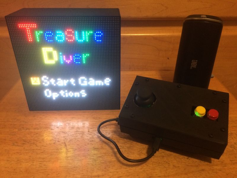
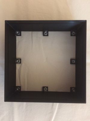
The Adafruit 64 X 64 LED matrix is responsible for displaying our Game elements to the player.
Hardware Design
The Technical Specifications of our Matrix are as follows:
- Brightness: 2800cd/square meter
- Size: 160x160mm
- Pitch: 2.5M
- 5 Addressable Pins
- Compatible with M3 mounting screws
- Scan: 1/32
- Refresh Frequency: >=400HZ
Two pin Sets, Input & Output, are located on the back of the Matrix along with a 2 VCC & 2 GND pins. The power pins require an external power supply capable of providing 5v at a bare minimum 4A of current, which were hooked up to a power supply via the spade connectors provided with the board . Any less than that will be insufficient if the whole board must be lit up. The input pins are where the Sjtwo microcontroller connects to drive this board. The output Pins are for chaining together multiple matrices together and was unused for this project. To drive the matrix, 14 GPIO pins were selected and made into output pins to control the input block of the matrix and two GND pins were used. The Pins and their connections are as follows:
| S.NO | RGB LED pins | Function |
|---|---|---|
| 1 | R1 | High R data |
| 2 | G1 | High G data |
| 3 | B1 | High B data |
| 4 | R2 | Low R data |
| 5 | G2 | Low G data |
| 6 | B2 | Low B data |
| 7 | A | Row select A |
| 8 | B | Row select B |
| 9 | C | Row select C |
| 10 | D | Row select D |
| 11 | E | Row select E |
| 12 | CLK | Clock signal. |
| 13 | OE | Output enables to cascade LED panel. |
| 14 | LAT | Latch denotes the end of data. |
| 15 | VCC | 5V |
| 16 | GND | GND |
The LEDs on the matrix are tricolor RGBs which means we have 8 color combinations at our disposal. Each color of each register is driven by one bit in a 3 bit shift register (3 bits for 3 colors). Those bits are then controlled by the RGB pins on the matrix. The board contains 4096 LEDs and has a scan rate of 1:32. A scan rate simply states what percentage of the LEDs are ON at any given time. So 4096/32 means that 128 LEDs are active on the board at any given time. This number divided by two neatly translates into 64 which is one row of our LED Matrix. The matrix is spilt into two halves, a lower and upper portion, and data is sent to those halves through the RGB pins. RGB1 denotes the upper 32 rows of the board and RGB2 denotes the bottom 32 rows. Of our 128 active LEDs, one row in the lower and upper portions is lit up each. The shift registers for each LED are daisy chained together to allow us to drive all LEDs in a row at the same time. To select which row we light up we use the 5 address pins A,B,C,D,E. 5 pins means we have 2^5 = 32 addressable rows we can select.
The CLK pin is used to signal the arrival of one bit of data. The CLK must be toggled every time data is entered for one LED. The LATCH pin is used to signal the end of a row of data. Latch must be pulled high to control the Address Pins and then pulled back down to signal that the row has been selected. Output Enable (OE) is also set high with Latch to turn off the LEDs while the row is being selected and then clr low to turn them back on.
Software Design
Implementation
Now knowing what the hardware is like we can set the steps to draw one pixel on the board like so:
- Represent what color you wish to draw to board using 3 bits
- Now determine if the LED you want to light up is in the UPPER or LOWER parts of the board and choose RGB1 or RGB2 pins respectively to set
- Set the bits and Clock them in with the rest of the LEDs by toggling the CLK (You can set the other LEDs to be off by clocking in zero)
- Once a full row has been entered, disable Output and set Latch High
- Using A,B,C,D,E pins, specify the row your target LED is on
- Set Latch back down to low and re-enable the Output
Representing our colors is done by driving (or not driving) the RGB pins on the matrix. R means red, G means blue, and B means blue and setting those bits together results in a color combo of the set set bits. Three pins means we only need three bits to represent the color we want. If the Sjtwo board is going to be picking the LEDs to draw it would be very handy if it had its own internal representation of the matrix. We can do so with a matrix!
uint8_t led_matrix[ROW_LENGTH][COL_LENGTH];
In this 2d array we can say in each column of each row represent one LED. Now we also know that if an LED is located in the upper portion of the Board(Rows 0 - 31) its going to need to use the RGB1 and if in the lower portion (Rows 32-63) then its going to use the RGB2 pins. Since the color to write to the board is only 3 bits why not say the location of those bits determines which set of pins to drive?
//If RGB denotes my color and I want to light up red and my LED is at the first Row then I can say the entry for that matrix looks like
uint8_t color = 0b100 //Red, but not blue or green
led_matrix[0][desired_led] = color;

//But if my LED is in the upper portion I can shift the bits up three positions
led_matrix[35][desired_led] = color<<3;
This gives the Sjtwo board the ability to distinguish which Pins it must set to get the desired color at the desired location and so now we can update all the values of our board like so:
void led_driver__updateDisplay(void) {
 for (uint8_t row = 0; row < 64; row++) {
   for (uint8_t col = 0; col < 64; col++) {
     if (led_matrix[row][col] & 0x1) {
       gpio__set(B1);
     } else {
       gpio__reset(B1);
     }
     if (led_matrix[row][col] & 0x2) {
       gpio__set(G1);
     } else {
       gpio__reset(G1);
     }
     if (led_matrix[row][col] & 0x4) {
       gpio__set(R1);
     } else {
       gpio__reset(R1);
     }
     if (led_matrix[row][col] & 0x8) {
       gpio__set(B2);
     } else {
       gpio__reset(B2);
     }
     if (led_matrix[row][col] & 0x10) {
       gpio__set(G2);
     } else {
       gpio__reset(G2);
     }
     if (led_matrix[row][col] & 0x20) {
       gpio__set(R2);
     } else {
       gpio__reset(R2);
     }
     ClockToggle();
   }

   disableOutput();
   LatchEnable();

   ClearAddressLines();

   if (row & 0x1) {
     gpio__set(A);
   }
   if (row & 0x2) {
     gpio__set(B);
   }
   if (row & 0x4) {
     gpio__set(C);
   }
   if (row & 0x8) {
     gpio__set(D);
   }
   if (row & 0x10) {
     gpio__set(E);
   }
   LatchDisable();
   enableOutput();
 }
}
The last problem to solve is that our board requires a refresh frequency >=400HZ. We can use tasks calls this function constantly to update the board at a frequency dependent on the VtaskDelay():
void updateBoard(void *p) {

 while (1) {
   led_driver__updateDisplay();
   vTaskDelay(3);
 }
}
MP3 Decoder
The YX5300 MP3 Music Player Module is used in the project to play music at the menu, gameplay and at the Victory/Gameover screen. Although we use it to decode MP3 files, it can also decode MAV files. This board contains a slot for SD card mounting, which we command the module to read from. Insert diagram of MP3 decoder connected to sj2 (using pictures of actual modules)
Hardware Design
This module is easy to interface since it only uses UART pins (Rx and Tx), excluding the Vcc and Ground. A voltage level of 3.3V was used to power the board, and was supplied from the SJ2 board. The MP3 decoder was connected to 2 of SJ2's port 2 pins that have UART functionality. The baud rate required for communication is 9600 bps. This decoder also contains an audio jack to connect headphones or speakers.
Software Design
For ease of code reading, memory was unionized so it may be accessed as an array and by variable names that correspond to the command packet format that is specified in the module's datasheet. The SJ2 board initializes UART for communicating to the MP3 decoder and allocates memory to load packet information before sending via Tx line. Before sending any other command, we must command the decoder to select device 2 (as described in the datasheet).
In the project we wait for an event, such as entering the title screen or game to start playing music.
Below, are snippets of the code used to setup the commands and send them. A command we used in our Treasure Diver project was to cycle through music in one folder. The function that send this command is called mp3_decoder__Cycle_play_folder(). Within commands, there are two function calls for setting up the packet (set_command_and_data()) and the other for sending the packet over UART (send_command()). For more information on the command packet, see the implementation section.
void mp3_decoder__cycle_play_folder(uint8_t folder) {
  set_command_and_data(mp3_decoder__cycle_folder, folder, no_data);
  send_command();
}

static void set_command_and_data(uint8_t command, uint8_t data0, uint8_t data1) {
  command_message.decoder_command_byte.command_byte = command;
  command_message.decoder_command_byte.data_byte0 = data0;
  command_message.decoder_command_byte.data_byte1 = data1;
}

static void send_command(void) {
  uint8_t i = 0;
  while (i < 8) {
    if (uart__polled_put(uart, command_message.decoder_command.bytes[i])) {
      i++;
    }
  }
}
Implementation
The datasheet specifies the command packet to the MP3 decoder to be a minimum size of 8 bytes composed of the START, VERSION, LENGTH, COMMAND, FEEDBACK, DATA (min of 2 bytes), and END bytes. To make the implementation self explanatory and easy to use (via array), the commands were placed in a unionized memory location (shown below). This approach made it easier
typedef struct {
  uint8_t bytes[8]; ///< 8 bytes of a mp3 decoder message
} mp3_decoder__command_t;

typedef union {
  mp3_decoder__command_t decoder_command; ///< 64-bit command message to decoder
  struct {
    uint64_t start_byte : 8;    // Will be set to 0x7E
    uint64_t version_byte : 8;  // Will be set to 0xFF
    uint64_t data_length : 8;   // Will be set to 0x06
    uint64_t command_byte : 8;  // Varies
    uint64_t feedback_byte : 8; // Will be set to 0x00
    uint64_t data_byte0 : 8;    // Varies
    uint64_t data_byte1 : 8;    // Varies
    uint64_t end_byte : 8;      // Will be set to 0xxEF
  } decoder_command_byte;
} mp3_decoder__msg_t;
The commands were structured as an enum for dedicated functions to use in setting command_byte in the command packet via decoder_command_byte members. Once the command is set, the packet is accessed as an array to simplify sending over UART.
Bluetooth Interface
We used two HC-05 bluetooth modules for our project, one on the game pad controller board acting as master, and one on the matrix controller board acting as slave. The master bluetooth module transmitted joystick, accelerometer, and button press data to the slave bluetooth module. The slave bluetooth module transmitted controller input type data (accelerometer or joystick) to the master bluetooth module.
We decided to go with the HC-05 variant of bluetooth modules because they are easy to setup, easy to use, and extremely reliable to the point that we didn't have a single issue with either of these modules. We liked the configurability of the HC-05 because it could be adapted to suit the needs of different projects through its many configuration options. Configuration was done by using AT commands to configure one bluetooth module as master, the other as slave, and to set the UART baud rate to 38400. Additionally, we chose to "lock" the master bluetooth module to its corresponding slave module to prevent it from pairing with another bluetooth device in range.
Hardware Design
The HC-05 modules were connected to each board using the same SJ2 pin numbers (UART peripheral #3 on P0.0 and P0.1). Each HC-05 communicates with its respective SJ2 board through a UART interface. The game pad controller SJ2 board processes the button press and joystick signals and sends them to it's bluetooth module via UART. This bluetooth module then send this data to the other bluetooth module. The received button press and joystick signals are then sent to the matrix controller SJ2 board via UART in order for them to be processed. The same logic applies for sending controller input type data (joystick or accelerometer) from the matrix controller SJ2 board to the game pad controller SJ2 board.
Software Design
Before the tasks are started on each board, the UART3 peripheral is initialized and the SJ2's P0.0 and P0.1 pins are set to UART pin functions. Each SJ2 board has a "transmit to bluetooth" and "receive from bluetooth" task in order to constantly transmit and receive commands to/from its connected bluetooth module. The matrix controller board's transmit task transmits the controller input type data that the user has selected in the options menu. The matrix controller's receive task receives all data sent from the game pad controller's bluetooth device and passes the received data into a handler function. The handler determines what string was received and then calls our controls API to set the proper button presses and character movement.
The game pad controller board's transmit task transmits the joystick/accelerometer direction data, and button press data. The transmit task has a function that calls transmit functions for each type of data to be sent; select button, cancel button, joystick button, and accelerometer/joystick direction data. The game pad controller's receive task receives all data sent from the matrix controller's bluetooth device and passes the received data into a handler function. The handler determines what string was received and then calls our controls API to set the proper controller input type.
Implementation
The bluetooth driver implementation consisted of initializing the UART3 interface (with transmit and receive queues enabled) between the SJ2 and bluetooth module, and comparing the string received from the bluetooth module with several pre-defined strings in order to determine what command was actually received. For example, if the joystick is tilted upward, the game pad's bluetooth module sends the string "N\r\n", which is the exact string that the matrix controller's bluetooth module receives. This received string is compared against all of the commands we have defined to find a match. In this case, a match will be found with pre-defined string "N\r\n", and so the "set character movement direction to N" function is called.
The matrix controller's received strings are processed by the handler function below that compares the received string against every command that we have defined.
Matrix Controller Received Bluetooth Commands
- SELECT - select button on the game pad was pressed
- CANCEL - cancel button on the game pad was pressed
- CENTERED - character shouldn't move
- N - move character up (N direction)
- NE - move character NE (not used)
- E - move character right (E direction)
- SE - move character SE (not used)
- S - move character down (S direction)
- SW - move character SW (not used)
- W - move character left (W direction)
- NW - move character NW (not used)
void bluetooth_handler__process_received_bluetooth_command(char string[]) {
  if (strcmp(string, "SELECT\r\n") == 0) {
    controls__set_SELECT_button_pressed(true);
  } else {
    controls__set_SELECT_button_pressed(false);
  }

  if (strcmp(string, "CANCEL\r\n") == 0) {
    controls__set_CANCEL_button_pressed(true);
  } else {
    controls__set_CANCEL_button_pressed(false);
  }

  if (strcmp(string, "CENTERED\r\n") == 0) {
    controls__set_joystick_direction(CENTERED);
  } else if (strcmp(string, "N\r\n") == 0) {
    controls__set_joystick_direction(N);
  } else if (strcmp(string, "NE\r\n") == 0) {
    controls__set_joystick_direction(NE);
  } else if (strcmp(string, "E\r\n") == 0) {
    controls__set_joystick_direction(E);
  } else if (strcmp(string, "SE\r\n") == 0) {
    controls__set_joystick_direction(SE);
  } else if (strcmp(string, "S\r\n") == 0) {
    controls__set_joystick_direction(S);
  } else if (strcmp(string, "SW\r\n") == 0) {
    controls__set_joystick_direction(SW);
  } else if (strcmp(string, "W\r\n") == 0) {
    controls__set_joystick_direction(W);
  } else if (strcmp(string, "NW\r\n") == 0) {
    controls__set_joystick_direction(NW);
  }
}
The matrix controller's transmit strings are sent by the transmit function below. This function is called in a task to continuously transmit this data to the game pad controller board.
void bluetooth_driver__transmit_controller_input_type_data(void) {
  controller_t controller_input = controls__get_controller_input_type();
  char data_to_send[20];

  switch (controller_input) {
  case JOYSTICK:
    sprintf(data_to_send, "JOYSTICK\r\n");
    break;
  case ACCELEROMETER:
    sprintf(data_to_send, "ACCELEROMETER\r\n");
    break;
  default:
    sprintf(data_to_send, "JOYSTICK\r\n");
    break;
  }

  int buffer_index = 0;
  while (data_to_send[buffer_index] != '\0') {
    uart__put(UART__3, data_to_send[buffer_index], 0);
    buffer_index++;
  }
}
The game pad controller's received strings are processed by the handler function below that compares the received string against every command that we have defined.
Game Pad Controller Received Bluetooth Commands
- JOYSTICK - set the controller input type to joystick
- ACCELEROMETER - set the controller input type to accelerometer
void bluetooth_handler__process_received_bluetooth_command(char string[]) {
  if (strcmp(string, "JOYSTICK\r\n") == 0) {
    controls__set_controller_input_type(JOYSTICK);
  } else if (strcmp(string, "ACCELEROMETER\r\n") == 0) {
    controls__set_controller_input_type(ACCELEROMETER);
  }
}
The game pad controller's transmit strings are sent by the transmit functions below. These functions are called in a task to continuously transmit this data to the matrix controller board. For simplicity, only the select button's transmit function is shown below but the transmit function looks the same for all other button presses (the word "select" is just replaced with the other button press's signal name).
static void bluetooth_driver__transmit_SELECT_button_data(void) {
  char data_to_send[20];
  sprintf(data_to_send, "SELECT\r\n");

  int buffer_index = 0;
  while (data_to_send[buffer_index] != '\0') {
    uart__put(UART__3, data_to_send[buffer_index], 0);
    buffer_index++;
  }

  controls__set_SELECT_button_pressed(false);
}

static void bluetooth_driver__transmit_joystick_data(void) {
  joystick_direction_t joystick_direction = controls__get_joystick_direction();
  char data_to_send[20];

  switch (joystick_direction) {
  case CENTERED:
    sprintf(data_to_send, "CENTERED\r\n");
    break;
  case N:
    sprintf(data_to_send, "N\r\n");
    break;
  case NE:
    sprintf(data_to_send, "NE\r\n");
    break;
  case E:
    sprintf(data_to_send, "E\r\n");
    break;
  case SE:
    sprintf(data_to_send, "SE\r\n");
    break;
  case S:
    sprintf(data_to_send, "S\r\n");
    break;
  case SW:
    sprintf(data_to_send, "SW\r\n");
    break;
  case W:
    sprintf(data_to_send, "W\r\n");
    break;
  case NW:
    sprintf(data_to_send, "NW\r\n");
    break;
  default:
    sprintf(data_to_send, "CENTERED\r\n");
    break;
  }

  int buffer_index = 0;
  while (data_to_send[buffer_index] != '\0') {
    uart__put(UART__3, data_to_send[buffer_index], 0);
    buffer_index++;
  }

  controls__set_joystick_direction(CENTERED);
}
Game Pad Controller
The main components in Game Pad controller are a joystick, accelerometer, two buttons, and bluetooth. The controller is used to send commands and control Steve (the main character) in Treasure Diver, along with navigation of the menus, with the joystick or the SJ2's on-board accelerometer (user's choice). With bluetooth on the game pad, the controller is wireless.
Hardware Design
The setup of the game pad's hardware was very simple. The two push buttons (cancel and select) use the same configuration. Both are use a pull up resistor when open (not pressed) and short to ground when pressed. This was done to improve the signal and make sure the SJ2 gpio would read high or low. The accelerometer was easy to initialize since there was already existing API. So, all it required was was reading and properly handling the data to send the command to the master board to control Stave. The joystick require initializing. Although, the input of both was different, the output was essentially the same. The accelerometer and joystick both had analog outputs which would then be read by an analog to digital converter (ADC).
The outputs would represent the X and Y positions of both devices. The analog stick was also a button that could be pressed, but it was not implemented in the project, due to time constraints.
Software Design
When the software is sending commands, it gets the ADC values and analyzes which direction the accelerometer or joystick is indicating. The flow primarily checks up/down and if it is one of these, then L/R is checked. If one of these is true, the software checks which direction is a greater magnitude. This approach is used for both the accelerometer and joystick.
As an example for more clarity, if DOWN is true and RIGHT is true, we then check which directions has a greater value. If the joystick/accelerometer is leaning more in the DOWN direction, then the game pad will send this direction to the Master board.
joystick_direction_t joystick_controls__get_joystick_direction(void) {
  joystick_direction_t joysticks_direction = CENTERED;
  const joystick_s current_position = get_joystick_position();

  if (check_up(current_position.y)) {
    if (check_left(current_position.x)) {
      if (current_position.y < (-1 * current_position.x)) {
        joysticks_direction = W;
      } else {
        joysticks_direction = N;
      }
    } else if (check_right(current_position.x)) {
      if (current_position.y < current_position.x) {
        joysticks_direction = E;
      } else {
        joysticks_direction = N;
      }
    } else {
      joysticks_direction = N;
    }
  } else if (check_down(current_position.y)) {
    if (check_left(current_position.x)) {
      if ((-1 * current_position.y) < (-1 * current_position.x)) {
        joysticks_direction = W;
      } else {
        joysticks_direction = S;
      }
    } else if (check_right(current_position.x)) {
      if ((-1 * current_position.y) < current_position.x) {
        joysticks_direction = E;
      } else {
        joysticks_direction = S;
      }
    } else {
      joysticks_direction = S;
    }
  } else {
    if (check_left(current_position.x)) {
      joysticks_direction = W;
    } else if (check_right(current_position.x)) {
      joysticks_direction = E;
    }
  }
Implementation
The axis of the joystick did not match the X and Y of our board positioning. To "rotate" the axis, the function swap_and_shift_axis() was created. The swap really occurs if the ADC port of X-axis is passed to the function so it can return a value to the game pad's Y-axis. The purpose of the shift is to make it easier when checking magnitudes of two different directions, as explained in the previous section.
static uint16_t swap_and_shift_axis(adc_channel_e axis) {
  const uint16_t shift_value = 2250;
  int16_t axis_value = adc__get_channel_reading_w_burst_mode(axis) - shift_value;

  return axis_value;
}

static joystick_s get_joystick_position(void) {
  static joystick_s joystick_pos;

  joystick_pos.x = swap_and_shift_axis(Y_AXIS);
  joystick_pos.y = swap_and_shift_axis(X_AXIS);

  return joystick_pos;
}
Technical Challenges
CAD Enclosures Design
- When we received the 3D printed enclosures, some of the holes were smaller than designed. This can happen in FDM printing because plastic is melted and placed layer by layer, which is only accurate to a certain thickness and height. In order to enlarge the holes, a needle file was used to file down the openings until the hole was big enough.
- Due to the COVID pandemic, we were unable to access the free 3D printing services offered by SJSU and so we had to pay to get our enclosures printed. Our original design was extremely costly and so the enclosures had to be redesigned twice in order to bring the cost down to an affordable amount. All the redesigning we had to do took a lot of time away from the other aspects of our project and the resulting enclosures were not as fancy as we originally planned, but it was all we could afford.
PCB Design
- Our first design of the matrix controller PCB had incorrect pin spacing for the led matrix pins because we accidentally used the wrong footprint. Unfortunately, we didn't notice this until after we had placed the PCB order and so we had to oder a second matrix controller PCB that had the correct matrix pin spacing. Fortunately, we noticed this before our order shipped and so we were able to add the corrected PCB design to our order without any additional delays.
LED Matrix
- When testing the game, we observed that if the character hit an obstacle and the joystick direction moving the character towards the obstacle was held for over a second or so, the game character would actually start to move into the obstacle. We realized that this was because the collision detection wasn't updating quick enough, and so we changed the collision detection's task priority from low to high. Using high priority for the collision detection task solved this problem.
- Ghosting was some time an issue in which an after image of an obstacle or image would sometimes linger on screen. This may happen because the GND pins on the Sjtwo board are not soldered correctly. After switching over to a PCB to connect the LED and board these issues stopped happening.
MP3 Decoder
- The datasheet lacks some information and clarity on initializing the module and with some of the commands. When first using it, non of the commands appeared to work or have any effect. The issue was resolved after sending the command to select a device, which was not explicitly stated in the datasheet. Once this command is first sent, the MP3 decoder now begins accepting commands.
Bluetooth Interface
- During testing, we realized that once a bluetooth command was sent, it would repeatedly send instead of just being sent once. For example, when the select button was pressed on the game pad, the select command would continuously send even though the button had been released and was no longer pressed. This is just how the bluetooth device works and so we had to make some modifications in our bluetooth handler code to accommodate this. In order to solve the button press data re-sending issue, we set button press to false immediately after receiving a button press command. In order to solve the joystick/accelerometer data re-sending issue, we defined a default state (CENTERED) which means no character movement, so it didn't matter that the centered command was being sent continuously.
Game Pad Controller
- Originally, thresholds for each direction were checked without comparing to another, and it would cause the character to go in a direction that was not intended or not move. When adding comparisons of magnitudes, character control greatly improved.
Advice for Future Students
CAD Enclosures Design
- If the 3D printing services offered by the library and SCE club aren't available (due to COVID pandemic), then use Jinxbot. They are the cheapest local option we found and offer shipping or you can pick up locally in Mountain View. They print extremely quickly, we got our prints 3 days after ordering.
PCB Design
- Use EasyEDA to design your PCBs. It has an auto-routing feature so you don't have to perform any routing by hand which saves you so much time. It also automatically converts your schematic to components that you just "drag and drop" onto your PCB while the connections are automatically maintained.
- Order your PCBs from JLCPCB (integrated into EasyEDA). You'll get them in 1 week.
- In EasyEDA, may sure you check the connections for each footprint you're using. Sometimes the footprint's pinout won't exactly match your schematic.
- Create a google sheet for all team members to fill out with the SJ2 pins they are using for there device/task. It will help prevent multiple people from using the same pins that may cause confusion down the road and include the voltage required for their device. This will help simplify PCB design when referencing this document. Also include an image of the SJ2 board's pins for referencing while filling out the sheet.
LED Matrix
- START EARLY AND FINISH THE LED DRIVER ASAP The longer you take to implement the driver, the more time you have to wait before you can do any actual game development. You will really start feeling it towards the last week where you want to add polish to your game but you no longer have time. You do not want to catch yourself saying "Just one more week".
- For the more artistically gifted amongst you, GIMP and MtPaint (open source) are fantastic resources for planning out levels and designing images. For example you can draw out your image and then using a python script or other image processing software you can get 2d array representation of your image that you can place your code. This is going to be much easier than writing entire screens out by hand:
- Additionally, there are other software tools that can be used to design these screens or other objects for the LED matrix. Pixelable was an app used on the iPad, which allowed exporting the created images and could be opened in MtPaint, if needed.
MP3 Decoder
- We were not successful in getting the single cycle command to work for the MP3 decoder so that we would play a specific song in a folder in have it on repeat. So, instead of having SFX, Title/Menu music and level music in there own folders, I created a folder for each song (shown in image below). This allowed us to use the command that cycles all the music in one folder, essentially having the desired result.
Bluetooth Interface
- Using this HC-05 bluetooth terminal app (also linked in reference section) will really help when you're trying to get your bluetooth modules configured initially and during testing/debugging of your bluetooth interface. We were also able to use this app as a game pad to control our character's movement on the LED matrix and send button press signals, which was useful for the members of our team who didn't have a second SJ2 board.
Game Pad Controller
- Create a function that prints the X and Y values of the accelerometer and/or joystick. It will be useful for debugging and further understanding the device.
Conclusion
We really enjoyed the process of making this project and have learned so much. Our driver writing skills were honed through writing drivers for each module we used (LED matrix, MP3 decoder, Bluetooth, etc.), our understanding of FreeRTOS API has increased, and we gained some basic game and graphics development skills through the LED matrix aspects of this project. Throughout the entire duration of this project, we encountered numerous challenges such as difficulty getting the LED matrix driver up and running, figuring out how to implement collision detection with so many game objects, writing and maintaining our complex game logic state machine and much more. Additionally, we experienced challenges due to the COVID pandemic particularly for the 3D printing aspects of this project, as we did not have access to SJSU's 3D printing services for students and had to pay a premium price to get our enclosures printed. Due to time constraints, there were parts of our project that had to be changed or couldn't be implemented and so future improvements that we'd like to add would be a fancier matrix enclosure, auto-scrolling during gameplay, adding the in-between cardinal directions for character movement (NE, NW, SE, SW), and assigning a functionality to the switch button on our gamepad's joystick. Despite the challenges and setbacks we faced, we were able to overcome every single one of them in order to build a finished product that we are all proud of.
Project Video
Project Source Code
Acknowledgements
We would like to thank our professor Preet and all the ISA's for putting together such a great class and for setting high expectations. This always inspired us to go above and beyond.
References
LED Matrix
- Everything You Didn't Want to Know About RGB Matrix Panels
- Mtpaint Source & Documentation
- AdaFruit walk Through for LED Matrix Wiring
MP3 Decoder
HC-05 Bluetooth Modules
- HC-05 Bluetooth AT Commands
- HC-05 Bluetooth Configuration & Pairing
- HC-05 Bluetooth Terminal App for Testing
3D Printing
