Difference between revisions of "S20: Tesla Model RC"
(→Tesla Model RC) |
(→Team Members & Responsibilities) |
||
| (316 intermediate revisions by the same user not shown) | |||
| Line 3: | Line 3: | ||
== '''Tesla Model RC''' == | == '''Tesla Model RC''' == | ||
| − | [[File:Tesla_model_RC_front.jpg| | + | [[File:Tesla_model_RC_front.jpg|540px|middle]] |
| − | [[File: | + | [[File:Tesla_model_RC_back_new.jpg|540px|middle]] |
| + | [[File:Tesla_model_RC_app_LCD.jpg|540px|middle]] | ||
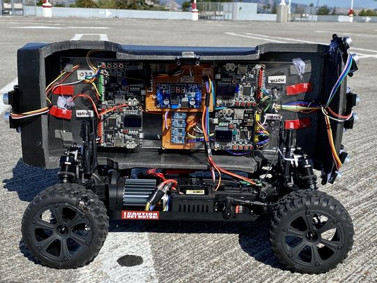
| + | [[File:Tesla_model_RC_inside.jpg|540px|middle]] | ||
| + | |||
| Line 25: | Line 28: | ||
=== '''Team Members & Responsibilities''' === | === '''Team Members & Responsibilities''' === | ||
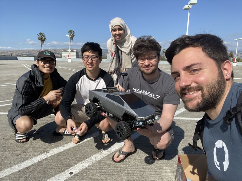
| − | [[File:Team_picture.jpg| | + | [[File:Team_picture.jpg|800px|middle|center]] |
| + | |||
| + | |||
| − | [[File: | + | [[File:Profile-Picture.jpeg|200px|middle]] |
| − | [https://www.linkedin.com/in/ | + | *'''''[https://www.linkedin.com/in/salvatore-nicosia/ Salvatore Nicosia]''''' '''''[https://gitlab.com/snicosia Gitlab]''''' |
| + | ** <font color="CDCC1C"><B>Motor Controller</B></font> | ||
| + | ** <font color="orange"><B>Geographical Controller</B></font> | ||
| + | ** <font color="red"><B>System Integration and Testing</B></font> | ||
| + | ** <font color="brown"><B>RC Car Design: 3D Printing</B></font> | ||
| − | < | + | [[File:Nick-headshot.png|200px|middle]] |
| − | * | + | *'''''[https://www.linkedin.com/in/nickolas-schiffer-a9487b13a Nickolas Schiffer]''''' '''''[https://gitlab.com/nickschiffer Gitlab]''''' |
| + | ** <font color="CDCC1C"><B>Motor Controller</B></font> | ||
| + | ** <font color="orange"><B>Geographical Controller</B></font> | ||
| + | ** <font color="orange"><B>Architecture Design</B></font> | ||
| − | |||
| − | |||
| − | |||
| − | + | [[File:dn_bio.png|200px|middle|Bridge Sensor Node]] <br/> | |
| − | * | + | *'''''[https://www.linkedin.com/in/danny-nuch/ Danny Nuch]''''' '''''[https://gitlab.com/dnuch Gitlab]''''' <br/> |
| + | ** <font color="violet"><B>Bridge Sensor Controller</B></font> | ||
| − | |||
| − | |||
| − | |||
| − | * <font color="PURPLE"><B>Driver & LCD Controller</B></font> | + | [[File:as_bio.jpg|200px|middle]] |
| − | + | *'''''[https://www.linkedin.com/in/ayesha-siddiqua-336064103/. Ayesha Siddiqua]''''' ''''[https://gitlab.com/asiddiqua Gitlab]''''' | |
| + | ** <font color="PURPLE"><B>Driver & LCD Controller</B></font> | ||
| − | |||
| − | |||
| − | + | [[File:Ak bio.jpeg|200px|middle]] | |
| − | + | *'''''[https://gitlab.com/choppr Andrew Kwon]''''' | |
| + | ** <font color="blue"><B>Android Application</B></font> | ||
| − | |||
| − | |||
* <font color="green"><B>Review Team</B></font> | * <font color="green"><B>Review Team</B></font> | ||
| Line 311: | Line 316: | ||
| | | | ||
* <span style="color:green">Completed</span> | * <span style="color:green">Completed</span> | ||
| − | * <span style="color: | + | * <span style="color:green">Completed</span> |
| − | * <span style="color: | + | * <span style="color:green">Completed</span> |
| − | * <span style="color: | + | * <span style="color:green">Completed</span> |
|- | |- | ||
|} | |} | ||
| Line 387: | Line 392: | ||
| SCE at SJSU [https://www.facebook.com/sjsusce/] | | SCE at SJSU [https://www.facebook.com/sjsusce/] | ||
| 4 | | 4 | ||
| − | | $ | + | | $160 |
|- | |- | ||
! scope="row"| 11 | ! scope="row"| 11 | ||
| Line 447: | Line 452: | ||
| Elenco [https://www.amazon.com/Elenco-Hook-Up-Colors-dispenser-WK-106/dp/B008L3QJAS] | | Elenco [https://www.amazon.com/Elenco-Hook-Up-Colors-dispenser-WK-106/dp/B008L3QJAS] | ||
| As needed | | As needed | ||
| − | | | + | | $22.55 + Tax |
|- | |- | ||
! scope="row"| 20 | ! scope="row"| 20 | ||
| Line 463: | Line 468: | ||
! scope="row"| 22 | ! scope="row"| 22 | ||
| 20x4 LCD Display Module | | 20x4 LCD Display Module | ||
| − | | [https://www.amazon.com/ | + | | LCD [https://www.amazon.com/gp/product/B0757BYC22/ref=ppx_yo_dt_b_search_asin_title?ie=UTF8&psc=1] |
| 1 | | 1 | ||
| − | | $ | + | | $29.99 |
|- | |- | ||
! scope="row"| 23 | ! scope="row"| 23 | ||
| Line 490: | Line 495: | ||
| 1 | | 1 | ||
| $5.82 + Tax | | $5.82 + Tax | ||
| + | |- | ||
| + | ! scope="row"| 27 | ||
| + | | | ||
| + | | | ||
| + | | Total | ||
| + | | $533.68 | ||
|- | |- | ||
|} | |} | ||
| Line 496: | Line 507: | ||
<BR/> | <BR/> | ||
| − | == | + | == Circuit Boards == |
| − | + | ||
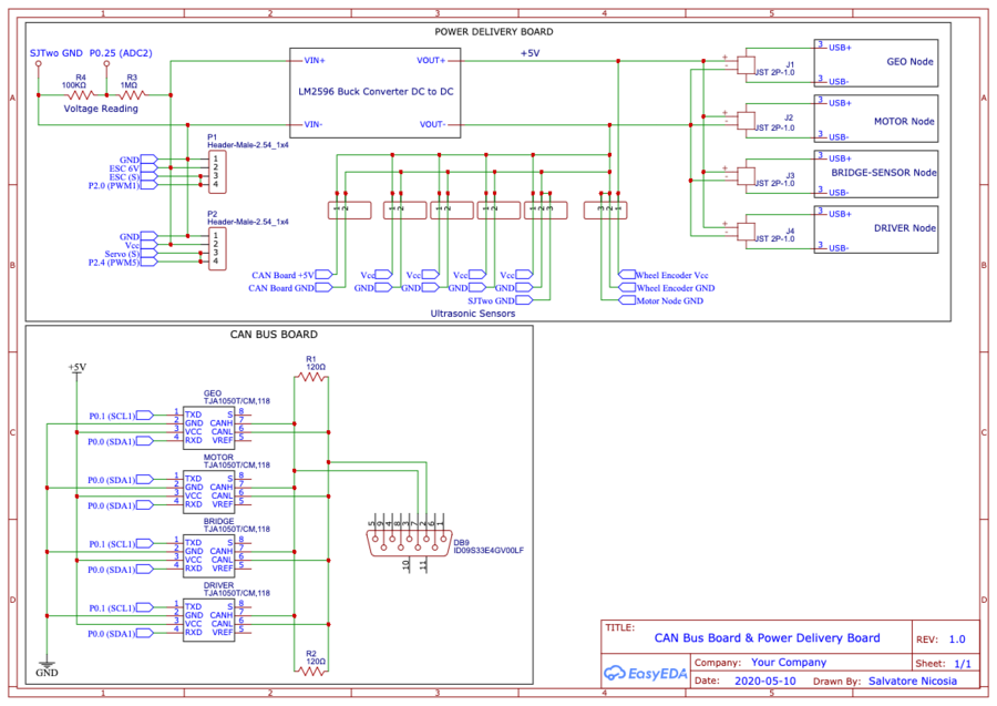
| − | < | + | Two circuit boards were designed to reduce the amount of wires and the necessity to use external power banks to deliver power to various modules. Both boards use #22 gauge wire which provides sufficient current flow to all the modules. The CAN board schematic shown below groups all the CAN transceivers in a single place so that the +5V power is shared among the CAN transceivers and are all close to the CAN bus. The power delivery board schematic shows how the power is taken from the main battery of the RC car and goes through a DC-DC buck converter to reduce the voltage to +5V from +7.2V. The +5V output of the buck converter delivers power to the CAN board, four SJTwo boards, 5 ultrasonic sensors, and wheel encoder. The output of the ESC in addition to powering the motor also powers the servo. Lastly, the power delivery board has a voltage reading point to monitor the voltage of the battery which is connected to the bridge sensor node. |
| + | |||
| + | [[File:Tesla_model_RC_schematics.png|thumb|900px|middle|center|CAN Bus Board & Power Delivery Schematic]] | ||
| + | |||
| + | |||
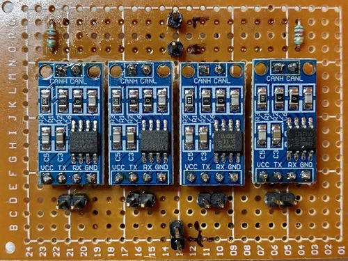
| + | Below are the two boards assembled. The CAN Bus board uses two 120Ω termination resistors, 2.54mm male headers to connect CAN Tx and CAN Rx of each SJTwo boards, and connected a DB9 connector on the bus to monitor and debug the state of the car through busmaster. | ||
| + | |||
| + | |||
| + | [[File:CAN_Board.jpg|thumb|500px|middle|center|CAN Bus Board]] | ||
| + | |||
| + | |||
| + | The power deliver board uses 2.54mm male headers for easier connection to the various modules and 4 JST 2-pin female connector to connect the micro USB cables that power the SJTwo boards. | ||
| + | |||
| + | |||
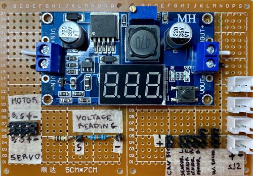
| + | [[File:Power_Board.jpg|thumb|500px|middle|center|Power Delivery Board]] | ||
| + | |||
| + | |||
| + | <HR> | ||
| + | <BR/> | ||
| + | |||
| + | ==Integrated System== | ||
| + | |||
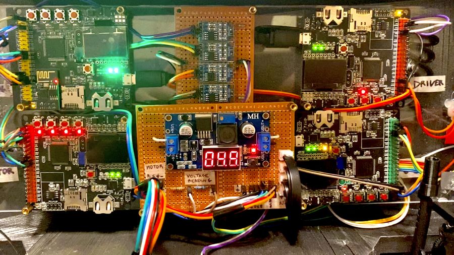
| + | In the picture shown below, is the integrated system connected to the SJTwo boards, CAN board, power deliver board, wheel encoder, motor, servo, GPS / Compass, and ultrasonic sensors. The WiFi module is directly placed on the dedicated pins of the SJTwo board of the bridge sensor node. | ||
| + | [[File:Tesla_model_RC_electronics.jpg|thumb|900px|middle|center|Integrated System]] | ||
| + | |||
| + | <HR> | ||
| + | <BR/> | ||
| + | |||
| + | == 3D Printed Parts== | ||
| + | |||
| + | ===Cybertruck 3D Model=== | ||
| + | |||
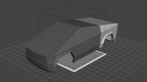
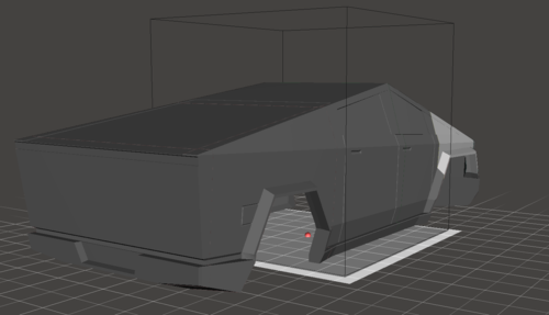
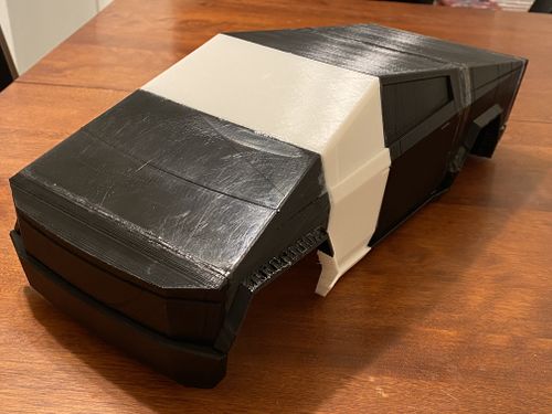
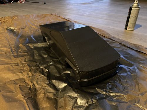
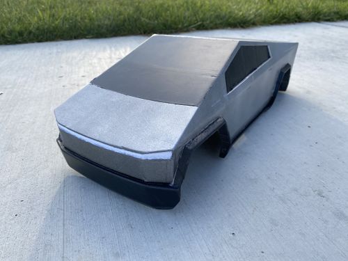
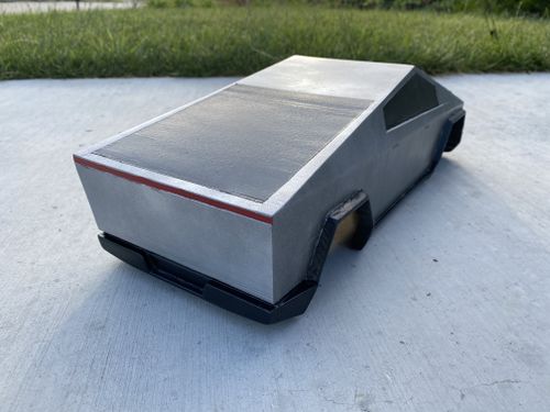
| + | This 3D model was modified and rescaled to fit the chassis of our car. Credit goes to the designer of the model which can be found on thingiverse at this [https://www.thingiverse.com/thing:4013549 link]. The shell was sliced into 6 parts to fit the building plate of the printer and make it easier to print the parts with minimal supports. Shown below are pictures of the 3D model as well as the printed and finished result of the shell. | ||
| + | |||
| + | [[File:Tesla_model_RC_shell_front.png|500px|middle]] | ||
| + | [[File:Tesla_model_RC_shell_back.png|500px|middle]] | ||
| + | [[File:Tesla_model_RC_shell_printed.jpg|500px|middle]] | ||
| + | [[File:Tesla_model_RC_shell_primer.jpg|500px|middle]] | ||
| + | [[File:Tesla_model_RC_shell_front_finished.jpg|500px|middle]] | ||
| + | [[File:Tesla_model_RC_shell_back_finished.jpg|500px|middle]] | ||
| + | |||
| + | ===Shell Supports=== | ||
| + | |||
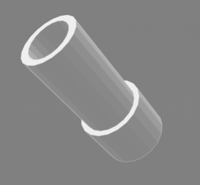
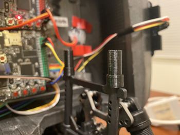
| + | These supports were designed to allow the shell to sit in place on the chassis by using 6 small magnets for each of the four corners. 4 magnets are inserted in each of these supports and 2 are attached in each corner to the plexiglass surface where the boards are mounted. | ||
| + | |||
| + | [[File:Tesla_model_RC_shell_support.png|290px|middle]] | ||
| + | [[File:Tesla_model_RC_shell_support_printed.jpg|350px|middle]] | ||
| + | |||
| + | ===Ultrasonic Sensor Supports=== | ||
| + | |||
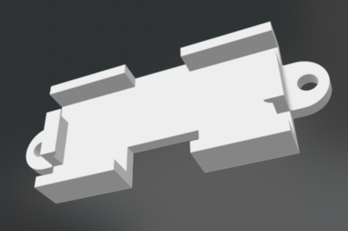
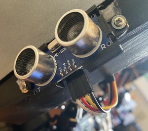
| + | The ultrasonic support 3D model was slightly resized to fit the HC-SR04 sensor. Credit goes to the designer of the model which can be found on thigiverse at this [https://www.thingiverse.com/thing:2157061 link]. | ||
| + | |||
| + | [[File:Tesla_model_RC_ultrasonic_mount.png|390px|middle]] | ||
| + | [[File:Tesla_model_RC_ultrasonic_mount_printed.jpg|300px|middle]] | ||
<HR> | <HR> | ||
<BR/> | <BR/> | ||
| + | |||
== CAN Communication == | == CAN Communication == | ||
| − | + | ||
| + | {| class="wikitable" style="text-align: center; margin-left: auto; margin-right: auto; border: none;" | ||
| + | |+ CAN Messaging Strategy | ||
| + | |- | ||
| + | ! Frequency | ||
| + | ! Message/Function | ||
| + | ! Message/Function | ||
| + | ! Message/Function | ||
| + | ! Message/Function | ||
| + | ! Message/Function | ||
| + | ! Message/Function | ||
| + | ! Message/Function | ||
| + | |||
| + | |- | ||
| + | | 1Hz | ||
| + | | Debug info | ||
| + | | Handle CAN bus Off | ||
| + | | - | ||
| + | | - | ||
| + | | - | ||
| + | | - | ||
| + | | - | ||
| + | |||
| + | |- | ||
| + | | 10Hz | ||
| + | | Handle WiFi Messages (GPS, start/stop states) | ||
| + | | Handle MIA Messages | ||
| + | | Handle GPS Coordinates | ||
| + | | Handle Motor & Steering Commands | ||
| + | | Handle Bridge Node Info (Battery Readings) | ||
| + | | Handle Compass heading & GPS bearing | ||
| + | | Handle Ranging Averaged Readings (front, left, right, back) | ||
| + | |||
| + | |} | ||
| + | |||
| + | *'''Bridge-sensor node''' | ||
| + | **Receives destination coordinates from android app and sends them over CAN to geographical node | ||
| + | **Receives vehicle navigation states from android app and sends them over CAN to driver node | ||
| + | **Sends ultrasonic sensors reading to driver node | ||
| + | **Sends battery voltage reading to driver node | ||
| + | |||
| + | *'''Driver node''' | ||
| + | **Sends speed and steering angle to motor node | ||
| + | |||
| + | *'''Geographical node''' | ||
| + | **Receives destination coordinates from bridge-sensor node | ||
| + | **Sends compass heading and gps bearing to driver node | ||
| + | **Sends distance to destination to driver node | ||
| + | |||
| + | *'''Motor Node''' | ||
| + | **Receives speed and steering messages from driver node | ||
| + | **Sends car's actual speed to driver and bridge-sensor node. | ||
=== Hardware Design === | === Hardware Design === | ||
| − | |||
| − | |||
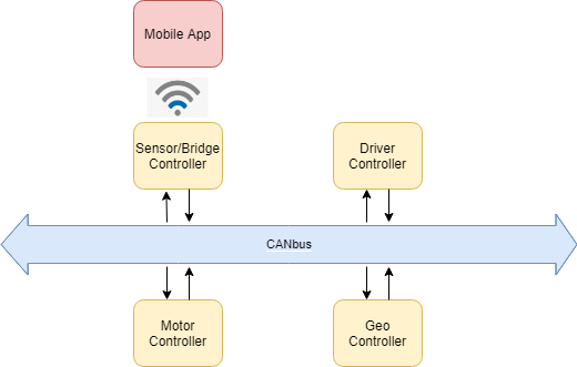
| − | [[File: | + | [[File:High level diagram.png|thumb|600px|middle|center|High Level Hardware Diagram]] |
=== DBC File === | === DBC File === | ||
| − | https://gitlab.com/tesla-model-rc/sjtwo-c/-/blob/dev/dbc/tesla_model_rc.dbc | + | |
| + | https://gitlab.com/tesla-model-rc/sjtwo-c/-/blob/dev/dbc/tesla_model_rc.dbc | ||
<HR> | <HR> | ||
<BR/> | <BR/> | ||
== Bridge Sensor ECU == | == Bridge Sensor ECU == | ||
| − | https://gitlab.com/tesla-model-rc/sjtwo-c/-/tree/dev/projects/sensor<br/> | + | https://gitlab.com/tesla-model-rc/sjtwo-c/-/tree/dev/projects/sensor<br/> |
| − | https://gitlab.com/tesla-model-rc/esp8266-coap-server | + | https://gitlab.com/tesla-model-rc/esp8266-coap-server |
=== Hardware Design === | === Hardware Design === | ||
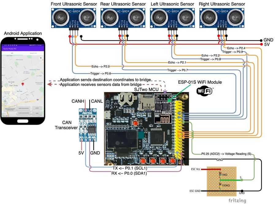
| − | [[File:Bridge_sensor_node.jpg|thumb|900px|middle|center| | + | [[File:Bridge_sensor_node.jpg|thumb|900px|middle|center|Bridge Sensor Node]] |
| − | {| class="wikitable" width="auto" style="text-align: center" | + | {| class="wikitable" width="auto" style="text-align: center; margin-left: auto; margin-right: auto; border: none;" |
| − | |+Table | + | |+Table 3. Bridge-Sensor Node Pinout |
|- | |- | ||
! scope="col"| SJTwo Board | ! scope="col"| SJTwo Board | ||
| Line 621: | Line 736: | ||
<u>Wifi module</u><br/> | <u>Wifi module</u><br/> | ||
| + | The Wifi module initializes UART channel 3 peripheral and the line buffer module. The line buffer module is used for parsing and handling Wifi messages transmitted over UART from the ESP8266. The Wifi line buffer has 128 bytes of allocated space and is filled at a rate of 100Hz from the UART queue. Then, at 10Hz the Wifi line buffer handler parses all lines found in the line buffer based upon the identifier found from a new-line delimited sequence of messages. These messages are specified in the ESP8266 section and set variables received from the mobile application to messages over CAN bus. The Wifi module also sends all four ultrasonic ranging values to the ESP8266 over UART allowing the mobile application to query ultrasonic diagnostics. | ||
| + | <u>Battery Tracking module</u><br/> | ||
| + | |||
| + | The Battery Tracking module is simply an ADC that receives the battery output as input. The ADC has a voltage reference of 3.3V and has a 12 bit resolution. Thus, the ADC conversion is 3.3V / 4095. The voltage divider set for the receiving battery voltage is a divider where R1 = 1M ohm and R2 = 100k ohm. Thus, the received ADC binary representation along with the ADC conversion value and the voltage multiplier gives the current battery voltage and is sent over the CAN bus. | ||
| − | |||
<u>Ultrasonics and GPIO Interrupts module</u><br/> | <u>Ultrasonics and GPIO Interrupts module</u><br/> | ||
| + | |||
| + | Ultrasonic sensors are initialized where each sensor has a trigger and echo pin. A trigger pin is used to initiate ranging from activating the trigger pin for 10 microseconds then setting it back to inactive. This will release an ultrasonic wave in the air that travels at the speed of sound. The reflection of the ultrasonic wave is sampled by the echo pin until the falling edge of an interrupt occurs where the time of flight of this wave is calculated from half of the round trip time by dividing by 2 as the distance is calculated as soon as the ultrasonic wave transmits and reflects from an obstacle and the speed of sound for converting to the distance traveled. The ultrasonic ranging calculation is (where tof = time of flight and sos = speed of sound):<br/> | ||
| + | |||
| + | ranging calculation in inches = (tof / 2) * sos = tof * (13503.9 in/s / 1000000 us) / 2 = tof * 0.00675195 in = (tof / 148.105) in | ||
| + | |||
<u>Average Buffer module</u><br/> | <u>Average Buffer module</u><br/> | ||
| − | Ultrasonic smoothing by averaging | + | |
| − | low pass filter | + | Ultrasonic smoothing is done by averaging a set amount of past ultrasonic values and sending out the averaged value over the CAN bus. This averages ranges that may be invalid due to an outlier. Ranges are collected at a 100Hz rate and are sent over CAN bus through a 10Hz function using a 10 slot sliding window average buffer where this buffer will be filled before the message is sent over CAN bus. A low-pass filter is implemented where zeroed values are replaced with the average value from the sliding window buffer. Zeroed ranges is a special case where a sensor receives ultrasonic waves immediately after the start of a trigger caused by scattered reflection of other ultrasonic waves in the air. |
<h4>ESP8266</h4> | <h4>ESP8266</h4> | ||
| − | Bridging between ESP8266 and mobile application is done through the creation of an access point on the ESP8266. Furthermore, the ESP8266 opens a server socket through CoAP allowing other CoAP clients to transmit or receive data from a created resource (/topics). The mobile application serves as the CoAP client and currently performs:<br/> | + | Bridging between ESP8266 and mobile application is done through the creation of an access point on the ESP8266. Furthermore, the ESP8266 opens a server socket through the Constrained Application Protocol (CoAP) allowing other CoAP clients to transmit or receive data from a created resource (/topics). The mobile application serves as the CoAP client and currently performs:<br/> |
| − | (GET) /heartbeat will receive string: "tmrc:heartbeat"<br/> | + | (GET) /heartbeat will receive string: "tmrc:heartbeat"<br/> |
| − | (GET) /getRadars will receive string: "aa,bb,cc,dd" where a is front radar, b is left radar, c is right radar, and d is back radar<br/> | + | (GET) /getRadars will receive string: "aa,bb,cc,dd" where a is front radar, b is left radar, c is right radar, and d is back radar<br/> |
| − | (PUT) /setStatus will send string - either "$stop\n" or "$start\n"<br/> | + | (PUT) /setStatus will send string - either "$stop\n" or "$start\n"<br/> |
| − | (PUT) /setCoordinates will send coordinates as string - i.e. "#Sxxx.xxxxxx,Syyy.yyyyyy\n" where S is the sign and x is latitude and y is longitude | + | (PUT) /setCoordinates will send coordinates as string - i.e. "#Sxxx.xxxxxx,Syyy.yyyyyy\n" where S is the sign and x is latitude and y is longitude |
/getRadars resource will update through UART from a microcontroller. The string must follow the format: "^%02,%02,%02,%02" where '^' is the identifier for setting this resource. This length is also fixed where each radar data must have a width of no more than 2.<br/> | /getRadars resource will update through UART from a microcontroller. The string must follow the format: "^%02,%02,%02,%02" where '^' is the identifier for setting this resource. This length is also fixed where each radar data must have a width of no more than 2.<br/> | ||
| Line 643: | Line 766: | ||
<u>Project Setup</u><br/> | <u>Project Setup</u><br/> | ||
This project is built with ESP8266 RTOS SDK for programming the ESP8266. FreeRTOS, UART, Wifi with CoAP libraries are fully utilized in this project.<br/> | This project is built with ESP8266 RTOS SDK for programming the ESP8266. FreeRTOS, UART, Wifi with CoAP libraries are fully utilized in this project.<br/> | ||
| − | See the Getting Started Guide for full steps to configure and use ESP-IDF to build projects.<br/> | + | See the Getting Started Guide from this SDK for full steps to configure and use ESP-IDF to build projects.<br/> |
<u>Wifi Access Point module</u><br/> | <u>Wifi Access Point module</u><br/> | ||
ESP8266 opens an access point for other wireless devices to connect too. This access point follows adaptation of this example:<br/> | ESP8266 opens an access point for other wireless devices to connect too. This access point follows adaptation of this example:<br/> | ||
| − | https://github.com/espressif/ESP8266_RTOS_SDK/tree/master/examples/wifi/getting_started/softAP.<br/> | + | https://github.com/espressif/ESP8266_RTOS_SDK/tree/master/examples/wifi/getting_started/softAP. |
| + | <u>UART Configuration module</u><br/> | ||
| + | UART is simply transmitted over UART0 TX/RX pins. This example is integrated:<br/> | ||
| − | + | https://github.com/espressif/ESP8266_RTOS_SDK/tree/master/examples/peripherals/uart_events | |
| − | |||
<u>CoAP Server module</u><br/> | <u>CoAP Server module</u><br/> | ||
CoAP server would startup a daemon task, create resources and receive data from CoAP clients and transmit data to CoAP clients. This server follows adaptation of a couple examples:<br/> | CoAP server would startup a daemon task, create resources and receive data from CoAP clients and transmit data to CoAP clients. This server follows adaptation of a couple examples:<br/> | ||
| + | https://github.com/espressif/ESP8266_RTOS_SDK/tree/master/examples/protocols/coap_server<br/> | ||
| + | https://github.com/obgm/libcoap-minimal/blob/master/server.cc<br/> | ||
| + | https://github.com/obgm/libcoap/blob/develop/examples/coap-server.c | ||
| + | The Constrained Application Protocol (CoAP) is a specialized web transfer protocol for use with constrained nodes and constrained networks in the Internet of Things. The protocol is designed for machine-to-machine (M2M) applications such as smart energy and building automation. Please refer to RFC7252 document for more details.<br/> | ||
| + | |||
| + | === Technical Challenges === | ||
| − | + | <h4>Ultrasonic Sensors Smoothing and Filtering</h4> | |
| − | |||
| − | |||
| − | The | + | The average buffer module had to be implemented as ultrasonics ranging values from a fixed distance had varying values. The average buffer module smoothed out ranging values by using an average sliding window of the last 10 ranges as the value sent over the CAN bus. In parallel to this average buffer, a low-pass filter is implemented where a value of zero would be replaced by the average of the sliding window buffer. This further smoothed the ultrasonic ranges by removing values that occurred upon reception of a radar wave right after a range is initiated through the trigger pin. |
| − | |||
| − | |||
| − | + | <h4>ESP8266 Flashing</h4> | |
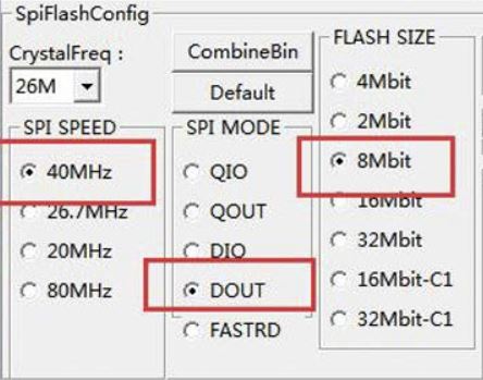
| − | + | [[File:ESPflashingProblem.JPG|center|Figure #. Software Flow diagram]] | |
| + | When flashing the ESP8266 be extremely observant about which mode the SPI should be configured. Different vendors will have SPI flash modes. | ||
<HR> | <HR> | ||
<BR/> | <BR/> | ||
== Motor ECU == | == Motor ECU == | ||
| − | https://gitlab.com/tesla-model-rc/sjtwo-c/-/tree/dev/projects/motor_node | + | https://gitlab.com/tesla-model-rc/sjtwo-c/-/tree/dev/projects/motor_node |
=== Hardware Design === | === Hardware Design === | ||
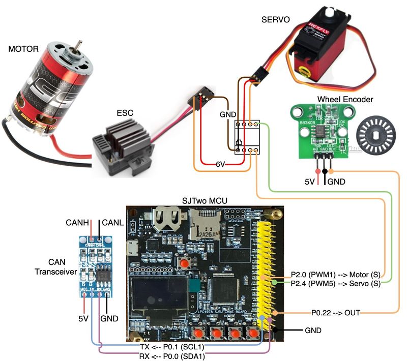
| − | [[File:Motor_node.jpg|thumb| | + | [[File:Motor_node.jpg|thumb|800px|middle|center|Motor Node]] |
| − | {| class="wikitable" width="auto" style="text-align: center" | + | {| class="wikitable" width="auto" style="text-align: center; margin-left: auto; margin-right: auto; border: none;" |
| − | |+Table | + | |+Table 4. Motor Node Pinout |
|- | |- | ||
! scope="col"| SJTwo Board | ! scope="col"| SJTwo Board | ||
| Line 724: | Line 851: | ||
|- | |- | ||
|} | |} | ||
| + | |||
| + | =====Wheel Encoder===== | ||
| + | |||
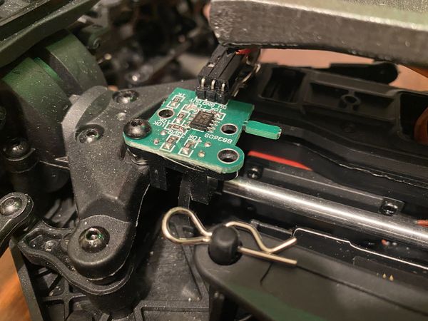
| + | The wheel encoder provides speed reading of the car by tracking the number of revolutions the disk makes through the reflection of the infrared light emitted by the sensor. This sensor was used to allow the car to go at constant speed when going uphill, downhill, or spots where the speed is reduced. | ||
| + | |||
| + | [[File:Wheel_encoder.jpg|thumb|600px|middle|center|Wheel Encoder]] | ||
=== Software Design === | === Software Design === | ||
| − | + | The main goal of the motor control node is to receive a requested speed and steering angle from the driver node and adjust the motor and steering angle accordingly such that those requested values are reached. | |
| + | |||
| + | Upon calling ''motor_control__initialize()'', the node initializes the necessary GPIO pins that are used to control the motor and steering servo. Additionally, it enables and attaches an interrupt to the pin that the wheel encoder is attached to. This directs the interrupts to trigger a callback that increments a count of rotor ticks which will later be used to calculate speed. | ||
| + | |||
| + | At this point, the ''run_once()'' function will begin to be called at 10Hz or every 100ms. ''The run_once()'' function calls the following functions: ''motor_control__handle_steering()'', ''motor_control__private_handle_rotor()'', and ''motor_control__handle_speed()''. | ||
| + | |||
| + | ''motor_control__handle_steering()'' simply maps the requested steering angle to a usable PWM value between the experimentally derived lower and upper PWM bounds for left and right. | ||
| + | |||
| + | ''motor_control__private_handle_rotor()'''s goal is to take the rotor tick counts since the last call, and calculate the average speed of the car over the last 100ms. It does this by following some simple geometry as shown: | ||
| + | |||
| + | const float distance_traveled_since_last_checkin_meters = ((float)rotor_tick_count / ticks_per_rotation) * wheel_circumference_cm / 100.0f; | ||
| + | const float average_speed_meters_per_second = distance_traveled_since_last_checkin_meters / ((float)time_elapsed_since_last_checkin_ms / 1000.0f); | ||
| + | const float average_speed_kilometers_per_hour = average_speed_meters_per_second * 3.6f; | ||
| + | // Deadlock Empire :) | ||
| + | gpiolab__disable_interrupts(); | ||
| + | rotor_tick_count = 0U; | ||
| + | gpiolab__enable_interrupts(); | ||
| + | latest_calculated_ground_speed_km_per_hour = average_speed_kilometers_per_hour; | ||
| + | motor_control__private_send_current_speed(); | ||
| + | |||
| + | |||
| + | First, the ''distance_traveled_since_last_checkin_meters'' is calculated based on how many ticks equal a wheel rotation, and the circumference of the car's wheel converted to meters. Once this is calculated, the average speed in meters per second can be derived from dividing the distance in meters by time in seconds. Next, to convert from meters per second to kilometers per hour, a simple conversion factor of 3.6 is used. | ||
| + | Once the average speed is found, the ''rotor_tick_count'' needs to be set back to 0 for the next round. Because that variable is being updated in an interrupt context, we need to temporarily disable the interrupts to this variable being updated by the interrupt and this function at the same time. | ||
| + | |||
| + | ''motor_control__handle_speed()'' utilizes a state machine to control the motor. This is because controlling the motor is very context-dependent and requires specifically timed control sequences to function properly. The states are as follows: | ||
| + | typedef enum { | ||
| + | SPEED_CONTROL_STATE__ESC_ARM_INITIALIZE = 0, | ||
| + | SPEED_CONTROL_STATE__ESC_ARM_WAIT_STATE, | ||
| + | SPEED_CONTROL_STATE__STOPPED, | ||
| + | SPEED_CONTROL_STATE__FORWARD, | ||
| + | SPEED_CONTROL_STATE__TRANSITION_TO_REVERSE_0, | ||
| + | SPEED_CONTROL_STATE__TRANSITION_TO_REVERSE_1, | ||
| + | SPEED_CONTROL_STATE__REVERSE | ||
| + | } motor_control__speed_control_states_e; | ||
| + | |||
| + | * The ''SPEED_CONTROL_STATE__ESC_ARM_INITIALIZE'' and ''SPEED_CONTROL_STATE__ESC_ARM_WAIT_STATE'' are the first states of the state machine. They are used to comply with the start-up/self-test sequence of the ESC that controls the motor. In these states, we must hold the throttle in the neutral position for around 3 seconds. After this time, the ESC will beep, indicating that its start-up/self-test sequence has completed. If this beep does not occur, the motor will not move. | ||
| + | * The next state is ''SPEED_CONTROL_STATE__STOPPED''. In this state, the neutral throttle PWM value is sent to the ESC which causes the motor to stop. Depending on the requested speed in this state, the next state will change to ''SPEED_CONTROL_STATE__FORWARD'' or ''SPEED_CONTROL_STATE__TRANSITION_TO_REVERSE_0''. | ||
| + | * The ''SPEED_CONTROL_STATE__FORWARD'' state is entered when the requested value from the driver node is above the forward threshold. The state machine enters this state from the ''SPEED_CONTROL_STATE__STOPPED'' state. In this state, the requested speed is compared to the current speed. Every 100ms iteration, (assuming the requested direction stays forward), there is logic to dynamically adjust the PWM value sent to the ESC to speed up or slow down to car. If the requested speed falls below the forward threshold, the state machine will re-enter the ''SPEED_CONTROL_STATE__STOPPED'' state. | ||
| + | * The ''SPEED_CONTROL_STATE__TRANSITION_TO_REVERSE_0'' is entered from the ''SPEED_CONTROL_STATE__STOPPED'' state if the requested speed is below the reverse threshold. Transitioning to reverse requires a carefully timed sequence of inputs to change the directional mode of the ESC. First, the PWM values are set to a reverse value in ''SPEED_CONTROL_STATE__STOPPED''. Next, ''SPEED_CONTROL_STATE__TRANSITION_TO_REVERSE_0'' will adjust the PWM values to the neutral position for 2 iterations (200ms). The the state is set to ''SPEED_CONTROL_STATE__TRANSITION_TO_REVERSE_1''. | ||
| + | * The ''SPEED_CONTROL_STATE__TRANSITION_TO_REVERSE_1'' sets the PWM value back into reverse for another 2 iterations (200ms). Once this state completes, the car will be able to reverse, otherwise, giving reverse throttle applies an electronic braking effect. | ||
| + | * The ''SPEED_CONTROL_STATE__REVERSE'' state works similarly to the ''SPEED_CONTROL_STATE__FORWARD'' state. It will first negate the current speed. This is because the rotor_encoder cannot determine which direction the wheels are turning, only the magnitude of the speed. Then, it will compare this value with the current requested speed and will adjust the PWM value each iteration to increase or decrease the throttle to achieve/maintain the requested speed. If the requested speed goes above the reverse threshold, it will then back into the ''SPEED_CONTROL_STATE__STOPPED'' state. | ||
=== Technical Challenges === | === Technical Challenges === | ||
| − | + | Throughout the development of this node there were many technical challenges. Some related to undocumented functionality, others due to physical construction constraints. | |
| + | * '''ESC Self-Test/Start-up sequence:''' The ESC (Electronic Speed Controller) for our car does not allow the wheels to turn unless the startup sequence has been performed. Unfortunately since our car came as a kit, there was no documentation available for the ESC. While connected to the included remote control, we attached oscilloscope probes to the pwm pins between the receiver and ESC. We then set up a capture to observe the signals upon startup. With some trial and error, we were able to program a sequence that allowed the ESC to pass this stage as described above in the Software Design. | ||
| + | * '''ESC Reverse Mode:''' While prototyping reverse functionality, we quickly realized that simply sending lower pwm values to the ESC would not make the car reverse. Again, using the included remote control allowed us to troubleshoot and solve the problem. This ESC (and many others in the hobby-electronics world) utilize a behavior that prevents the user from transition directly from forward to reverse. This is to both save the motor from unintentional damage from reversing while at a high speed, and also allows for the braking functionality. While using the included remote control we realized that to get into reverse from forward, one must transition from forward to reverse, back to neutral, and then back to reverse. These transitions also have to have take place over a certain time interval. Therefore, these states are visited multiple times within the state machine in order to hold these positions for a long enough amount of time. | ||
<HR> | <HR> | ||
| Line 737: | Line 912: | ||
== Geographical ECU == | == Geographical ECU == | ||
| − | https://gitlab.com/tesla-model-rc/sjtwo-c/-/tree/dev/projects/geo_node | + | https://gitlab.com/tesla-model-rc/sjtwo-c/-/tree/dev/projects/geo_node |
=== Hardware Design === | === Hardware Design === | ||
| − | [[File:Geo_node.jpg|thumb|900px|middle|center| | + | |
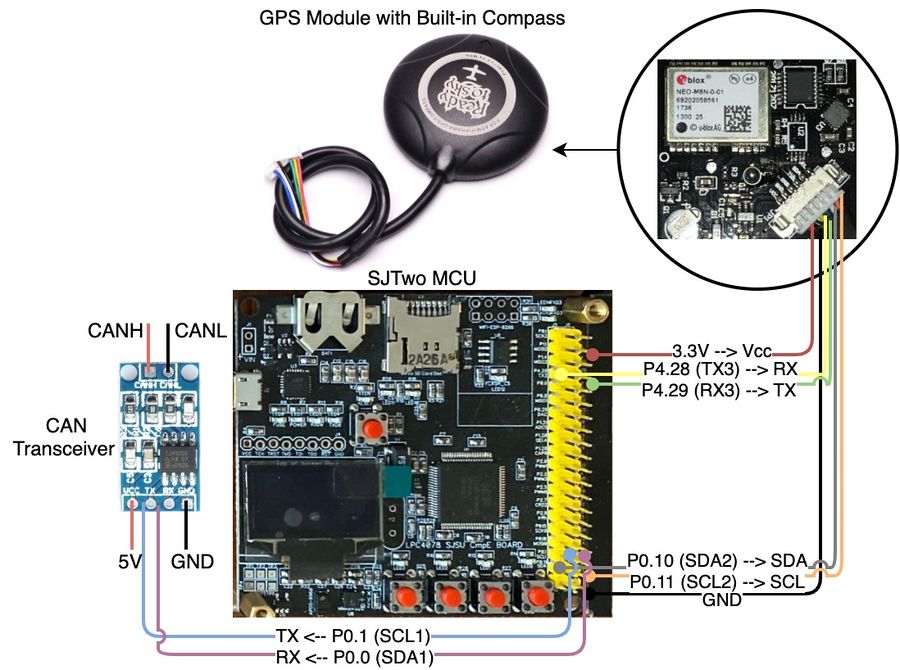
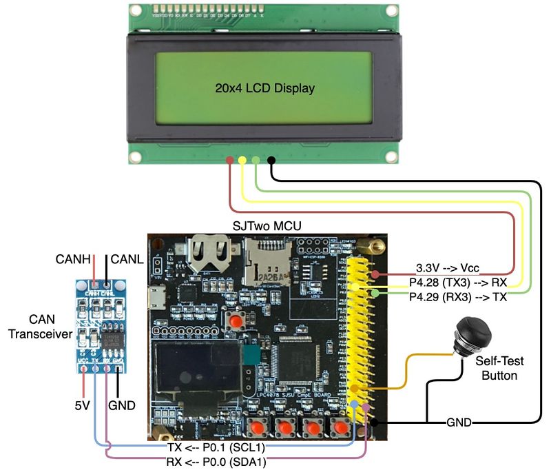
| − | {| class="wikitable" width="auto" style="text-align: center" | + | The geographical controller is interfaced to the readytosky GPS with built-in compass and a CAN transceiver as shown in the figure below. The readytosky module uses the Ublox NEO-M8N GPS which provides great accuracy and customization. In addition, it uses the 3-Axis compass HMC5883L magnetometer which provides a 1 to 2 degrees compass heading accuracy. The Ublox GPS module communicates with the SJTwo board via UART whereas the HMC5883L communicates with the SJTwo board via I2C. The CAN transceiver is interfaced to the CAN Bus and allows reception and sending of CAN messages via the CAN pins on the SJTwo board. When the driver node goes MIA the geographical controller lights an LED indicating the MIA status of the node. |
| − | |+Table | + | |
| + | [[File:Geo_node.jpg|thumb|900px|middle|center|Geo Node]] | ||
| + | |||
| + | {| class="wikitable" width="auto" style="text-align: center; margin-left: auto; margin-right: auto; border: none;" | ||
| + | |+Table 5. Geographical Node Pinout | ||
|- | |- | ||
! scope="col"| SJTwo Board | ! scope="col"| SJTwo Board | ||
| Line 792: | Line 971: | ||
=== Software Design === | === Software Design === | ||
| − | + | ====Overview==== | |
| + | |||
| + | The geographical node calls periodically the following code modules: | ||
| + | |||
| + | *gps.c | ||
| + | *compass.c | ||
| + | *checkpoint.c | ||
| + | *geological.c | ||
| + | *can_bus_message_handler.c | ||
| + | |||
| + | These modules, calculate compass heading degree, bearing, parse GPS coordinates, calculate the checkpoints the RC car has to go through when navigating to a destination, send distance to destination to driver node, and handle messages received on the CAN bus. | ||
| + | |||
| + | *'''The period_callbacks__initialize() function calls the following functions:''' | ||
| + | **can_bus_initializer__init(): initializes the CAN bus to handle MIA and messages. | ||
| + | **geological__init(): initializes the GPS, compass, and checkpoint algorithm. | ||
| + | |||
| + | *'''The period_callbacks__1Hz() function calls the following function:''' | ||
| + | **can_bus_initializer__handle_bus_off() | ||
| + | |||
| + | *'''The period_callbacks__10Hz() function calls the following functions:''' | ||
| + | **can_bus_message_handler__manage_mia_10Hz() to manage MIA signals. | ||
| + | **can_bus_meesage_handler__handle_all_incoming_messages_10Hz() to handle messages on the CAN bus (e.g. destination coordinates from Bridge sensor node). | ||
| + | |||
| + | ====GPS==== | ||
| + | |||
| + | =====Initialization===== | ||
| + | In the initialization process of the GPS, the line buffer module is configured to parse the GPS messages, the GPIOs P4.28(Tx) and P4.29(Rx) are configured, UART interrupt queues enabled, and the UART is configured at a baudrate of 9600. | ||
| + | |||
| + | =====Configuration===== | ||
| + | In the gps__run_once_10Hz() the GPS is initially configured once to disable all NMEA messages except GNGGA which is message chosen to parse the coordinates and GPS lock. | ||
| + | |||
| + | =====Parsing NMEA GNGGA messages===== | ||
| + | The GPS module constantly transmits NMEA GNGGA messages over UART to the SJTwo MCU. These messages which come in the form of a string are stored character by character in the line buffer until a new line character which indicates the end of string. The stored string is then extracted from the line buffer and the checksum is verified to ensure that the message is not corrupted. The extracted line is then tokenized to parse the latitude, latitude direction, longitude, longitude direction, and fix quality. South and West directions are also properly handled to make the latitude and longitude negative values. | ||
| + | |||
| + | =====GPS lock===== | ||
| + | The GPS lock is a function in the gps.c module that has the job to set a bool flag and blink an LED when the fix quality is either 1 or 2 in the GNGGA message. When the fix quality is one of those values it means the GPS has acquired a good connection to the satellites and the data received is valid. The LED blinking functionality was used for debugging purposes indicating the GPS has a lock. Whereas the bool flag was used as a condition to calculate the bearing and checkpoints only when the GPS had a lock meaning that the current coordinates were valid. | ||
| + | |||
| + | ====Compass==== | ||
| + | |||
| + | =====Initialization===== | ||
| + | The compass initialization configures the HMC5883L magnetometer registers over I2C bus to default settings using a gain of 1090 and single mode. | ||
| + | |||
| + | =====Heading degree computation===== | ||
| + | The compass heading degree is computed by using the tilt compensation algorithm and the pitch and roll values calculated from the SJTwo accelerometer. The tilt compensation algorithm ensures that the values of the compass heading are precise within an error of 1 to 2 degrees when the compass is tilted in all directions. Shown below are the formulas used to compute the heading degree referenced from this [https://www.pololu.com/file/0J434/LSM303DLH-compass-app-note.pdf link]. | ||
| + | |||
| + | '''Pitch and Roll:'''<br/> | ||
| + | |||
| + | pitch = asin(-accelerometer_x_axis) <br/> | ||
| + | roll = asin(accelerometer_y_axis / cos(pitch) | ||
| + | |||
| + | '''Tilt compensated magnetic sensor values for x and y:'''<br/> | ||
| + | |||
| + | Mx_c = (Mx - offset_x_axis) * cos(pitch) + Mz * sin(pitch)<br/> | ||
| + | My_c = (Mx - offset_x_axis) * sin(roll) * sin(pitch) + (My - offset_y) * cos(roll) - Mz * sin(roll) cos(pitch) | ||
| + | |||
| + | *where: | ||
| + | **Mx_c = Magnetometer x-axis tilt compensated | ||
| + | **My_c = Magnetometer y-axis tilt compensated | ||
| + | **Mx = Magnetometer x-axis value | ||
| + | **My = Magnetometer y-axis value | ||
| + | **Mz = Magnetometer z-axis value | ||
| + | |||
| + | The offset values for x and y are calculated during calibration to reduce soft-iron and hard-iron distortions. Soft-iron distortions are generally caused by nearby metals such nickel and iron in which distorts the existing magnetic field of the compass depending in which direction the field acts. Hard-iron distortions are produced by objects that generate a magnetic field such as the motor of the RC car causing a permanent bias in the compass sensor if not corrected. | ||
| + | |||
| + | To calculate the scale factors for x and y to reduce soft-iron distortions the following equations were used: | ||
| + | |||
| + | a = (max_y - min_y) / (max_x - min_x) <br/> | ||
| + | b = (max_x - min_x) / (max_y - min_y) | ||
| + | |||
| + | x_scale = a > 1.0 ? a : 1.0;<br/> | ||
| + | y_scale = b > 1.0 ? b : 1.0; | ||
| + | |||
| + | To calculate the offset for x and y to reduce hard-iron distortions the following equations were used: | ||
| + | |||
| + | offset_x = ((max_x + min_x) / 2.0) * x_scale<br/> | ||
| + | offset_y = ((max_y + min_y) / 2.0) * y_scale | ||
| + | |||
| + | '''Heading angle''' | ||
| + | |||
| + | heading = azimuth = atan2(magnetometer_x_axis / magnetomer_y_axis) - π + 0.23 | ||
| + | |||
| + | To the heading is also added the declination angle which is based on location and in our case it is 0.23. This heading is calculated in radians since atan2 returns a value between -π and +π. Therefore, before converting the heading into degrees the value needs to be normalized to put it in the range from 0 to 360 degrees. | ||
| + | |||
| + | ====Geological.c module==== | ||
| + | |||
| + | =====Initialization===== | ||
| + | The geological.c module initializes the gps and compass with the configurations explained before. | ||
| + | |||
| + | =====Run once at 10Hz===== | ||
| + | Every 10Hz the geological_run_once() function periodically calls the gps module, gets the parsed coordinates, gets the compass heading degree, sets the current and destination coordinates, sends the calculated bearing degree over CAN to the driver node, and runs the checkpoint algorithm. | ||
| + | |||
| + | =====Bearing Angle computation===== | ||
| + | |||
| + | The bearing which is the angle towards our desired destination is computed using the formulas below referenced at this [https://www.igismap.com/formula-to-find-bearing-or-heading-angle-between-two-points-latitude-longitude/ link]. | ||
| + | |||
| + | X = cos θb * sin ∆L | ||
| + | Y = cos θa * sin θb – sin θa * cos θb * cos ∆L | ||
| + | |||
| + | β = atan2(X,Y) | ||
| + | |||
| + | *where: | ||
| + | **θa = current latitude | ||
| + | **θb = destination latitude | ||
| + | **∆L = destination longitude - current longitude | ||
| + | **β = heading degree in radians | ||
| + | |||
| + | The bearing is also calculated in radians since atan2 returns a value between -π and +π. Therefore, before converting the heading into degrees the value needs to be normalized to put it in the range from 0 to 360 degrees. The calculated bearing is then sent to the driver node which use the compass heading degree and the bearing to align the car toward the target destination. | ||
| + | |||
| + | ====Checkpoints Algorithm==== | ||
| + | |||
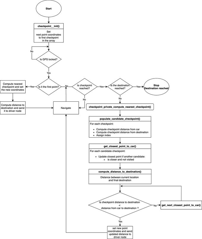
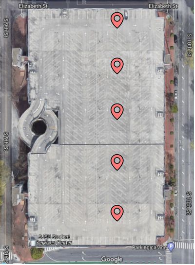
| + | The checkpoint algorithm depicted below uses a simple algorithm in which chooses the next point to navigate to if the checkpoint is the closest to the car while at the same time the closest to the destination. For the testing of our car navigation system, we choose the top floor of the north garage at San Jose State University as it provides a great open space and best signal for the GPS. In the figure shown below, five checkpoints were chosen in which the car can navigate to depending on where the destination is set to. Having fewer points rather then having too many reduces the amount of checkpoints the car has to move to and allows to reach the destination quicker while at the same time avoid areas such as the ramp in which the car should not go to. | ||
| + | |||
| + | [[File:checkpoint_algorithm_Tesla_model_RC.jpg|680px|middle|Figure #. Checkpoints Algorithm]] | ||
| + | [[File:Checkpoints_North_Garage.jpg|400px|middle|Figure #. Checkpoints North Garage]] | ||
| + | |||
| + | |||
| + | To calculate the geographical distance between the two points the haversine formula was used which is called periodically from the checkpoint.c module. Below is the formula used: | ||
| + | |||
| + | a = sin²(ΔlatDifference/2) + cos(lat1) * cos(lt2) * sin²(ΔlonDifference/2) | ||
| + | c = 2 * atan2(sqrt(a), sqrt(1−a)) | ||
| + | d = R * c | ||
| + | |||
| + | *where: | ||
| + | **ΔlatDifference = latitude 2 - latitude 1 (difference of latitude) | ||
| + | **ΔlonDifference = longitude 2 - longitude 1 (difference of longitude) | ||
| + | **R = 6371000.0 meters = radius of earth | ||
| + | **d = distance computed between two points | ||
| + | **a and c are intermediate steps | ||
| + | |||
| + | ====CAN messages==== | ||
| + | The geographical node periodically handles all incoming messages at 10Hz. The following messages are received by the geographical node to set the destination and allow the computation of the bearing and checkpoints: | ||
| + | BO_ 106 BRIDGE_SENSOR_GPS_HEADINGS: 8 BRIDGE_SENSOR | ||
| + | SG_ BRIDGE_SENSOR_GPS_HEADINGS_LONGITUDE : 0|32@1- (0.000001, 0) [0|2000] "degrees" GEO, DRIVER | ||
| + | SG_ BRIDGE_SENSOR_GPS_HEADINGS_LATITUDE : 32|32@1- (0.000001, 0) [0|2000] "degrees" GEO, DRIVER | ||
| + | |||
| + | The geographical node periodically all sends messages at 10Hz. The following messages are sent by the geographical node: | ||
| + | |||
| + | BO_ 105 GEO_GPS_COMPASS_HEADINGS: 8 GEO | ||
| + | SG_ GEO_GPS_COMPASS_HEADINGS_CURRENT : 0|32@1- (0.000001,0) [0|360] "degrees" DRIVER, BRIDGE_SENSOR | ||
| + | SG_ GEO_GPS_COMPASS_HEADINGS_DESTINATION : 32|32@1- (0.000001,0) [0|360] "degrees" DRIVER, BRIDGE_SENSOR | ||
| + | |||
| + | BO_ 117 GEO_GPS_DISTANCE: 4 GEO | ||
| + | SG_ GEO_GPS_DISTANCE_TO_DESTINATION : 0|32@1- (0.000001,0) [0|0] "meters" DRIVER, BRIDGE_SENSOR | ||
=== Technical Challenges === | === Technical Challenges === | ||
| Line 799: | Line 1,120: | ||
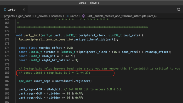
*'''Problem:'''The enabled 2-stop bits in uart.c were causing communication problems between the SJTwo MCU and the Ublox M8N GPS module. | *'''Problem:'''The enabled 2-stop bits in uart.c were causing communication problems between the SJTwo MCU and the Ublox M8N GPS module. | ||
| − | **'''Solution:'''To solve the 2 stop bits configuration was disabled in uart.c in the uart__init() function as shown in figure | + | **'''Solution:'''To solve the issue the 2 stop bits configuration was disabled in uart.c in the uart__init() function as shown in the figure below. |
| − | [[File:2-stop-bits.png|thumb|700px|middle|center| | + | [[File:2-stop-bits.png|thumb|700px|middle|center|2-stop-bit configuration]] |
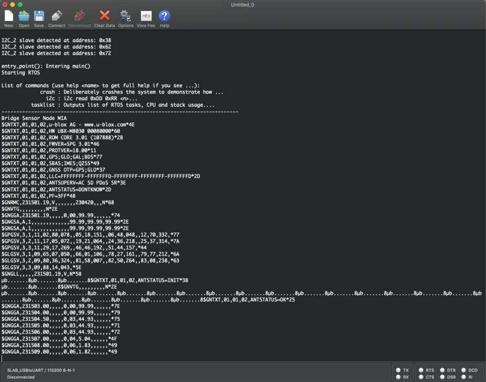
*'''Problem:'''GPS module did not retain configurations and were lost after being powered off for many hours going back back to default settings. This problem was crucial since it was causing the SJ2 to parse the latitude and longitude incorrectly from other messages other than NMEA GNGGA. | *'''Problem:'''GPS module did not retain configurations and were lost after being powered off for many hours going back back to default settings. This problem was crucial since it was causing the SJ2 to parse the latitude and longitude incorrectly from other messages other than NMEA GNGGA. | ||
| − | **'''Solution:''' To solve this configuration problem u-center which is an interface for the GPS Ublox module was used to read which strings the program sends over UART to configure the GPS module. This solution was implemented in the gps.c module creating a function called gps__private_configure_for_nmea_gngga() in which holds a char array with the hex representation of the configurations needed to disable all of the NMEA messages except GNGGA. This function then sends this configuration values back to the GPS module over UART and the GPS module responds back with an ACK message (8μ.......) from every configuration message meaning that the configurations were successfully applied as shown in figure | + | **'''Solution:''' To solve this configuration problem u-center which is an interface for the GPS Ublox module was used to read which strings the program sends over UART to configure the GPS module. This solution was implemented in the gps.c module creating a function called gps__private_configure_for_nmea_gngga() in which holds a char array with the hex representation of the configurations needed to disable all of the NMEA messages except GNGGA. This function then sends this configuration values back to the GPS module over UART and the GPS module responds back with an ACK message (8μ.......) from every configuration message meaning that the configurations were successfully applied as shown in the figure below. The function gps__private_configure_for_nmea_gngga() could not be called in the periodic_callbacks__initialize() function has it required more time to properly configure the GPS. As a solution, a bool flag indicating that the configuration was done was used along with calling gps__private_configure_for_nmea_gngga() in the gps_run_once_10Hz() to allow it properly configure the GPS module. |
| − | [[File:nmea_config_new.png|thumb|1000px|middle|center| | + | [[File:nmea_config_new.png|thumb|1000px|middle|center|GPS Module NMEA Configuration]] |
| Line 815: | Line 1,136: | ||
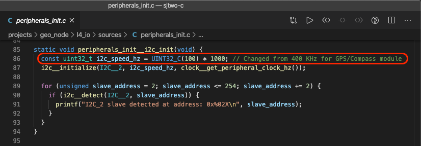
*'''Problem:'''SJTwo MCU could not detect the slave address of the HMC5883L magnetometer on the I2C Bus 2. | *'''Problem:'''SJTwo MCU could not detect the slave address of the HMC5883L magnetometer on the I2C Bus 2. | ||
| − | **'''Solution:'''Upon reading the HMC5883L datasheet it was mentioned that it works at 400KHz. However, this was not the case as changing the speed in peripherals__init.c module from 400KHz to 100KHz solved the issue and the SJTwo board successfully detected the HMC5883L 3-Axis Magnetometer. In | + | **'''Solution:'''Upon reading the HMC5883L datasheet it was mentioned that it works at 400KHz. However, this was not the case as changing the speed in peripherals__init.c module from 400KHz to 100KHz solved the issue and the SJTwo board successfully detected the HMC5883L 3-Axis Magnetometer. In the figure below is shown the function a long with change it was made. In addition, changing the speed did not affect the other modules using I2C Bus 2. |
| − | [[File:peripherals__init.png|thumb|900px|middle|center| | + | [[File:peripherals__init.png|thumb|900px|middle|center|peripherals__init.c]] |
*'''Problem:'''Compass heading degree true north was off by about 90 degree when compared to the compass of smart phone. This problem was due the fact the compass had to be completely flat to show proper values. In addition, the default calibration seemed also to be a problem in providing an accurate heading degree a long with hard iron and soft iron interferences. | *'''Problem:'''Compass heading degree true north was off by about 90 degree when compared to the compass of smart phone. This problem was due the fact the compass had to be completely flat to show proper values. In addition, the default calibration seemed also to be a problem in providing an accurate heading degree a long with hard iron and soft iron interferences. | ||
| − | **'''Solution:'''To solve these problems a function to calibrate the compass was implemented in which calculates offset and scale correcting for hard iron and soft iron interferences respectively. The process to calibrate consisted in turning the compass at different angles to collect as many sample points as possible and store offsets values of x and y axes in const variables which were then used in the equations to compute the heading degree. Although this corrected some of the imprecision problems, not having the compass completely flat still provided results that were not precise. To solve this issue the compass was compensated for tilt by using the built-in accelerometer of the SJTwo board which provides roll and pitch and the tilt compensation algorithm described at this [https://www.pololu.com/file/0J434/LSM303DLH-compass-app-note.pdf link]. The challenge in making this work properly was that the axes of the magnetometer and the axes of the accelerometer need to be perfectly aligned. However, after finalizing the place of the compass on the RC car it was fairly easy to align the axes. The tilt compensation system for the compass is | + | **'''Solution:'''To solve these problems a function to calibrate the compass was implemented in which calculates offset and scale correcting for hard iron and soft iron interferences respectively. The process to calibrate consisted in turning the compass at different angles to collect as many sample points as possible and store offsets values of x and y axes in const variables which were then used in the equations to compute the heading degree. Although this corrected some of the imprecision problems, not having the compass completely flat still provided results that were not precise. To solve this issue the compass was compensated for tilt by using the built-in accelerometer of the SJTwo board which provides roll and pitch and the tilt compensation algorithm described at this [https://www.pololu.com/file/0J434/LSM303DLH-compass-app-note.pdf link]. The challenge in making this work properly was that the axes of the magnetometer and the axes of the accelerometer need to be perfectly aligned. However, after finalizing the place of the compass on the RC car it was fairly easy to align the axes. The tilt compensation system for the compass is shown in the figure below. After including the tilt compensation algorithm the compass heading degree was off by 1-2 degrees when tilted in all directions drastically improving the accuracy from non-compensated in which the heading was off by 60-90 degrees when the compass was not held flat. |
| − | [[File:tilt_compensated_compass_system.jpg|thumb| | + | [[File:tilt_compensated_compass_system.jpg|thumb|700px|middle|center|Tilt Compensated Compass System]] |
| Line 838: | Line 1,159: | ||
== Driver Controller & LCD == | == Driver Controller & LCD == | ||
| − | https://gitlab.com/tesla-model-rc/sjtwo-c/-/tree/dev/projects/driver_controller_node | + | The driver node is the heart of the designed RC car. It receives appropriate messages from the bridge-sensor node and geo node and processes the signals before sending speed and steering values to the motor node. |
| + | |||
| + | https://gitlab.com/tesla-model-rc/sjtwo-c/-/tree/dev/projects/driver_controller_node | ||
=== Hardware Design === | === Hardware Design === | ||
| − | [[File:Driver_node.jpg| | + | [[File:Driver_node.jpg|thumb|800px|middle|center|Driver Node]] |
| − | {| class="wikitable" width="auto" style="text-align: center" | + | {| class="wikitable" width="auto" style="text-align: center; margin-left: auto; margin-right: auto; border: none;" |
| − | |+Table | + | |+Table 6. Driver Node Pinout |
|- | |- | ||
! scope="col"| SJTwo Board | ! scope="col"| SJTwo Board | ||
| Line 859: | Line 1,182: | ||
| LCD Tx data line | | LCD Tx data line | ||
| UART 3 | | UART 3 | ||
| + | |- | ||
| + | |- | ||
| + | | P0.15 | ||
| + | | +Vcc Button | ||
| + | | Button + | ||
| + | | | ||
|- | |- | ||
| P0.1 (SCL1) | | P0.1 (SCL1) | ||
| Line 883: | Line 1,212: | ||
=== Software Design === | === Software Design === | ||
| − | + | * LCD display | |
| + | **The LCD is used to display a few important signal values, which will help us monitor the car behavior when it's moving. | ||
| + | ** The communication with LCD is established using UART. | ||
| + | ** We have used a 20x4 LCD whose behavior was to print individual lines at a time. | ||
| + | ** Twoscreens were designed for the LCD depending on the state of the car. | ||
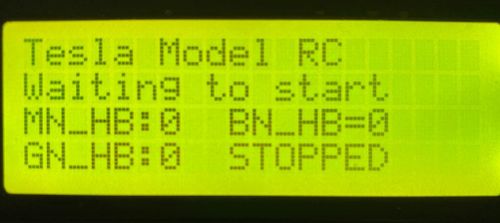
| + | ** The first screen displayed all node heartbeat values. The car will wait on this screen if any one of the node heartbeats is zero. | ||
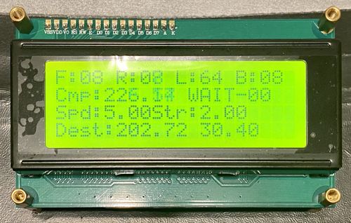
| + | ** The second screen displayed information from the multiple sensors. | ||
| + | ** The first line of the second screen has the front, right, left and back sensor information received from the sensor node | ||
| + | ** The second line has compass heading received from the geo node, the internal state of the driver state machine, and the checkpoint number. | ||
| + | ** The second line has speed and steering values sent to the motor node from the driver node. | ||
| + | ** The fourth line of the second screen has destination distance and heading received from the geo node. | ||
| + | [[File:LCD_init.jpg|thumb|500px|middle|center|LCD first Screen]] | ||
| + | [[File:Tesla_model_RC_LCD.jpg|thumb|500px|middle|center|LCD Second Screen]] | ||
| + | * Navigation state machine | ||
| + | **The car navigation is achieved with the help of a state machine. | ||
| + | **The main states of the state machine are INIT, WAIT, OBSTACLE, and NAVIGATE. | ||
| + | **The car waits in the INIT state till all the nodes provide the heartbeat. | ||
| + | ** The WAIT state has multiple components in it. The test button is added to the WAIT state. The car is in the WAIT state till a start signal is received from the mobile application. | ||
| + | ** When the start signal is received from the app the enters the OBSTACLE state. | ||
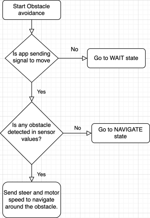
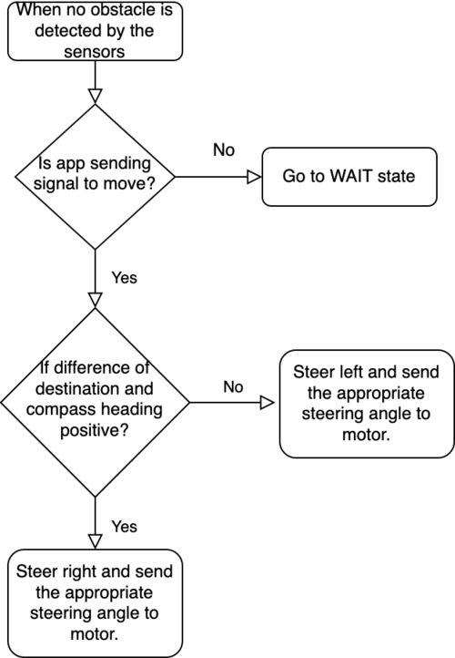
| + | ** The obstacle avoidance algorithm is simple. If there is no obstacle reported by the sensors then the car enters the NAVIGATE state. | ||
| + | [[File:obstacle_flowchart.png|thumb|500px|middle|center|OBSTACLE state in the driver state machine]] | ||
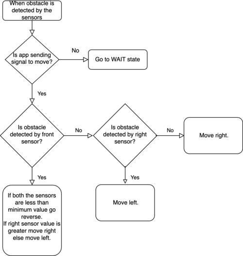
| + | ** If an obstacle is detected then another state machine is started which finds out the obstacle placement and the motor speed and steer values. | ||
| + | ** The below flowchart shows the obstacle avoidance algorithm. | ||
| + | [[File:obstacle_flowchart2.png|thumb|500px|middle|center|Obstacle avoidance algorithm]] | ||
| + | ** If no obstacle is detected then another state machine is started which finds out the correct navigation steering and the motor speed. | ||
| + | ** The navigation is calculated based on the destination and heading angle. | ||
| + | ** Care is also taken if the angles are greater than 180 degrees. | ||
| + | ** The below flowchart shows the navigation algorithm. | ||
| + | [[File:navigation_flowchart.png|thumb|500px|middle|center|Car navigation]] | ||
=== Technical Challenges === | === Technical Challenges === | ||
| − | + | * The initial reverse functionality worked when an obstacle was detected in front of all the sensors. This was causing problems when the car has no room to turn hard right and left. | |
| + | **This reverse functionality was improvised if any two sensors read values less than the minimum turning distance. | ||
| + | * A stop state was added in the motor node for reverse functionality but still issues were encountered during testing. | ||
| + | ** Stop state was also added in the reverse functionality along with delay in the reverse sate. | ||
| + | * To change the obstacle detection after taking a reverse initial process was to construct another state machine. | ||
| + | **Addition of simple hard right steer movement solved the issue. | ||
<HR> | <HR> | ||
| Line 893: | Line 1,255: | ||
== Mobile Application == | == Mobile Application == | ||
| − | < | + | https://gitlab.com/tesla-model-rc/mobile-app-CoAP-client |
| + | |||
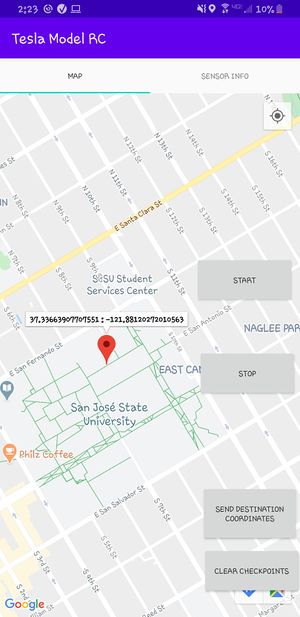
| + | [[File:Map_fragment.jpg|300px|Figure #. Software Flow diagram]] | ||
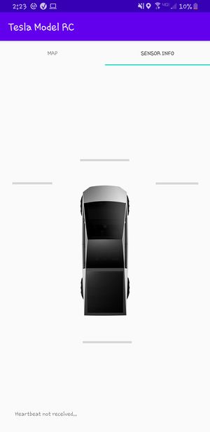
| + | [[File:Sensor_fragment.jpg|300px|Figure #. Software Flow diagram]] | ||
| + | |||
| + | === Application Communication === | ||
| + | |||
| + | Our App communicates with the Bridge/Sensor node through WiFi using the Constrained Application Protocol (CoAP). CoAP protocol has the benefits of transmitting smaller message packets since its underlying transport is UDP. CoAP works extremely well for point to point communication and doesn't require the full feature sets from TCP transportation.<br/> | ||
| + | *https://tools.ietf.org/html/rfc7252 | ||
| + | *https://jaime.win/lecture/coapdiscovery.html<br/><br/> | ||
| + | |||
| + | Because our App was written in Java, requirements were set such that the CoAP library to be imported must also be written in Java to be compatible with the App. After days of research we found several Java candidates of this protocol. Californium is a library that is constantly being updated and has the most documentation and most active community. WS4D was also a strong candidate because of its simple interface design. We chose WS4D over Californium because WS4D provides an interface for a CoAP Client that gave us the most flexibility on how we connect to end points and send/receive data.<br/> | ||
| − | === | + | *https://www.eclipse.org/californium/ |
| + | *http://ws4d.org/tag/coap/<br/><br/> | ||
| + | |||
| + | =====Pros and Cons===== | ||
| + | * The ESP8266 WiFi module was able to communicate with the App over very long distances. We were able to send POST messages from approximately 50 meters away. However power consumption on the App from the frequent message requests were draining the battery on the phone faster than normal. Bluetooth and Bluetooth LE has the advantage of being able to drain less power and run for longer periods of time on the App as well as the RC car.<br/> | ||
| + | * The length of the payload, or response to a GET request, has a maximum length of 16 bits. Any string data before being decoded, must fit this requirement. If a message fails to reach its destined end point, CoAP protocol will attempt to resend the message three times, before sending a failure response. One problem that arose was sending GET requests without verifying connection to the ESP8266 server. The buffer of unsent messages overflowed causing the Bridge node to receive unintentional error messages.<br/> | ||
| + | * Connecting to the WiFi Server was extremely easy. The network SSID and WPA2 key were hard coded parameters supplied to WifiManager object. You could also save the network on your phone as you would with your home WiFi. All the user would have to do is enable WiFi, since on start up, the app will disable current WiFi connections. If the auto-connect option for the network is checked, you would be able to instantly connect to the 'tesla_model_rc' access point. <br/> | ||
| + | One cool feature was that up to 3 phones could connect to the car at the same time and each send "start","stop", or send GPS coordinates. | ||
| + | |||
| + | === Application Design === | ||
| + | |||
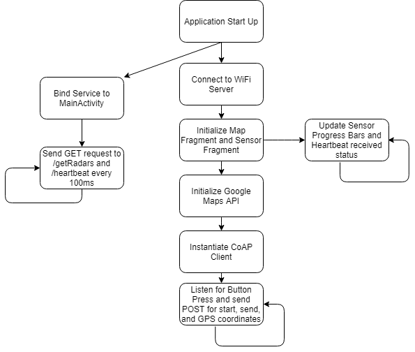
| + | Three fragments were created. Main Fragment, Sensor Fragment, and Map Fragment. The Sensor and Map fragment were embedded inside the Main Fragment. The design decision behind this was so that the Main fragment could easily access any layout resource defined in the .xml files of the Map fragment and Sensor Fragment. A TabLayout was used to switch between the Map fragment and Sensor Fragment. Each fragment had an Activity associated with its respective fragment. In the background, a Service is running. A Service must be bound to an application, in our case it was bound to the MainActivity and starts running when the app is opened. Its sole function is to obtain the CoAP Client instance and send GET requests to the /getRadars resource and /heartbeat resource at a frequency of 10hz. | ||
=== Software Design === | === Software Design === | ||
| − | + | [[File:AppSoftwareFlow.png|center|Figure #. Software Flow diagram]] | |
=== Technical Challenges === | === Technical Challenges === | ||
| − | < | + | * The main challenges I had were not realizing the difference between a Fragment and an Activity. I had created my Fragments without realizing they needed to exist within an Activity, so when my onClick methods for buttons weren't registering, it was because there was no underlying Activity attached with the Fragment. I would suggest to have a getInstance method for all the Fragments so that different Fragments can access or call different methods. <br/> |
| − | + | * I also had a problem with the Progress bars not updating based off the sensor values from the Sensor node. Solution was to update the Progress bars inside a handler that accessed the main UI thread.<br/> | |
| + | * There was a problem with the App not functioning properly on different Android Devices. Some buttons would not show up. I realized there are some button attributes in the layout file that caused this bug. <br/> | ||
| + | * Stackoverflow will be your best friend and make sure to consider every single answer, even the ones wit 0 upvotes. | ||
| − | |||
| − | |||
<HR> | <HR> | ||
<BR/> | <BR/> | ||
| + | |||
== Conclusion == | == Conclusion == | ||
| − | |||
| − | < | + | The Tesla Model RC project was a creative expression of our problem solving and design skills; developed during a challenging time for us personally and humanity in general. The outbreak of COVID-19, early in the semester, forced us to develop most of our project remotely and independently. It forced each member of our team to step up as leaders in their own right. Everyone had to manage their time and get their modules working, with little supervision and even less help. Clean code and unit testing became critical, as did good design and a cool temperament when things went wrong. As a team, we met expectations and developed an autonomous electric car that we are all deeply proud of. At the end of the day, our greatest strength was that all of us love what we do and love improving even more. <br/> |
| + | |||
| + | Our autonomous electric car was (obviously) inspired by Tesla's Cybertruck. The chassis itself was our tribute to the Cybertruck and to the electric vehicle industry. Integrating all modules, using CANbus, alleviated our concerns regarding signal integrity, the same way it did for Ford, BMW and Tesla. Writing the D.B.C file gave us a deep understanding of how CAN messages are composed and transmitted between the car's modules. Developing and integrating the Android mobile application educated us on wireless communication and the various tradeoffs between Wi-Fi, Bluetooth and Bluetooth Low Energy. Integrating all of our sensors and modules proved challenging, due to the limited time we had to meet up, but our car performed well when completed. <br/> | ||
| + | |||
| + | This semester was one of the richest learning experiences we have ever had. A truly practical graduate level project that we feel Elon Musk himself would appreciate. Thanks to Preet, Aakash, and Vignesh for all of their hard work this semester and to our classmates for sharing this experience with us. At the end of the day, these are hard times but not end times and we can all look forward to an electric future. <br/> | ||
=== Project Video === | === Project Video === | ||
| + | [https://www.youtube.com/watch?v=UBhPnGWChWI Tesla Model RC Demo Video] | ||
=== Project Source Code === | === Project Source Code === | ||
| + | * Git Project Link: <font color="fire"><U>[https://gitlab.com/tesla-model-rc Tesla Model RC ]</U></font> | ||
=== Advise for Future Students === | === Advise for Future Students === | ||
| − | < | + | * Before even touching any Android Studio code, read the following documents: |
| + | ** https://developer.android.com/guide/components/fragments | ||
| + | ** https://developer.android.com/guide/components/activities/intro-activities | ||
| + | * If the App requires a periodic task such as sending GET requests, I recommend to use a Service. It doesn't instantiate a new thread and runs off the main thread. | ||
| + | ** https://developer.android.com/guide/components/services <br/> | ||
| + | |||
| + | *You can verify that you can query POST/GET messages by creating a Server on the main thread and a Client on another thread within the same App. On the main thread, create a resource and an arbitrary payload value for that resource. The newly created thread acting as the Client should send a GET request to the Server running on the main thread and be able to receive the arbitrary payload value. The very first time I connected to the ESP8266, communication worked perfectly because I was able to verify it beforehand. | ||
| + | |||
| + | *Just like in industry, many technical problems will arise. The underlying problems and bugs will be difficult to trace if only one person is assigned to it. Therefore it's important to have as many eyes as possible to spot these issues. <br/> | ||
| + | |||
| + | * Communication is key. Every member should know the progress of every other member. What they are working on, how they are doing, and progress updates in general. Situations where "I'm waiting for this to be done, so I can work on that" should never be an excuse to start progress on any modules. We didn't experience this on a first hand basis which is why we were able to finish all our tasks on time. We recommend twice-a-week meetings of at least 10 minutes between all group members. Be proactive and ask your teammates for advice on any implementation detail. All members should know the basic functionality of all the modules. If you think you are done with your part, you aren't. There is always room for improvements and don't stop there. Ask other members if they need assistance and lastly be a team player. | ||
| − | + | * As the deadline comes closer, chances of feeling pressure is more likely. Working in a team will always come with more than just technical problems. It is always important to address any issue at hand as soon as you can, including personal and technical challenges. I advise future students to communicate both personal and technical issues they are facing throughout the project, in order to prevent any built-up tension and problems to resolve last-minute. This goes back to the twice-a-week 10-30 minute meetings. Set a couple days of the week and stick to it. These meetings will be beneficial for keeping all members aware of the high level functionality and progress of all modules. In case some modules are developing slower than others, everyone will be able to have the opportunity to assist as a consequence of these meetings. | |
=== References === | === References === | ||
| + | |||
| + | ====Bridge Sensor ECU==== | ||
| + | *[https://www.mpja.com/download/hc-sr04_ultrasonic_module_user_guidejohn.pdf HCSR-04] | ||
| + | *[https://github.com/espressif/ESP8266_RTOS_SDK ESP8266 RTOS SDK] | ||
| + | *[https://tools.ietf.org/html/rfc7252 RFC7252-CoAP] | ||
| + | |||
| + | ====Motor ECU==== | ||
| + | * None used | ||
| + | |||
| + | ====Geographical ECU==== | ||
| + | *[https://www.igismap.com/formula-to-find-bearing-or-heading-angle-between-two-points-latitude-longitude/ Bearing Formula] | ||
| + | *[https://www.igismap.com/haversine-formula-calculate-geographic-distance-earth/ Haversine Formula] | ||
| + | *[https://www.tutorialspoint.com/what-is-the-most-effective-way-for-float-and-double-comparison-in-c-cplusplus Float Comparison] | ||
| + | *[http://www.cypress.com/file/130456/download Compass calibration] | ||
| + | *[https://www.pololu.com/file/0J434/LSM303DLH-compass-app-note.pdf Compass Heading Tilt Compensated] | ||
| + | *[https://www.pololu.com/file/0J434/LSM303DLH-compass-app-note.pdf Magnetic declination] | ||
| + | *[https://github.com/adafruit/Adafruit_HMC5883_Unified/blob/master/examples/magsensor/magsensor.inoHMC5883L Adafruit Library] | ||
| + | *[https://github.com/jrowberg/i2cdevlib/blob/master/Arduino/HMC5883L/HMC5883L.h HMC5883L Arduino Library] | ||
| + | *[https://cdn-shop.adafruit.com/datasheets/HMC5883L_3-Axis_Digital_Compass_IC.pdf HMC5883L Datasheet] | ||
| + | *[https://www.u-blox.com/sites/default/files/NEO-M8-FW3_DataSheet_%28UBX-15031086%29.pdf Ublox NEO-M8 Datasheet] | ||
| + | *[https://www.u-blox.com/sites/default/files/products/documents/u-blox8-M8_ReceiverDescrProtSpec_%28UBX-13003221%29.pdf Ublox M8 Receiver Description] | ||
| + | |||
| + | ====Driver Controller and LCD==== | ||
| + | [https://www.rpigear.com/wp-content/uploads/2017/06/lcd-3.3V-20x4_datasheet.pdf/ LCD Serial driver from rpigear ] | ||
| + | |||
| + | ====Mobile Application==== | ||
| + | * https://developer.android.com/training/basics/firstapp | ||
| + | * https://www.youtube.com/watch?v=_xNkVNaC9AI&t=480s | ||
Latest revision as of 02:04, 12 July 2020
Contents
- 1 Tesla Model RC
- 2 Abstract
- 3 Schedule
- 4 Parts List & Cost
- 5 Circuit Boards
- 6 Integrated System
- 7 3D Printed Parts
- 8 CAN Communication
- 9 Bridge Sensor ECU
- 10 Motor ECU
- 11 Geographical ECU
- 12 Driver Controller & LCD
- 13 Mobile Application
- 14 Conclusion
Tesla Model RC
Abstract
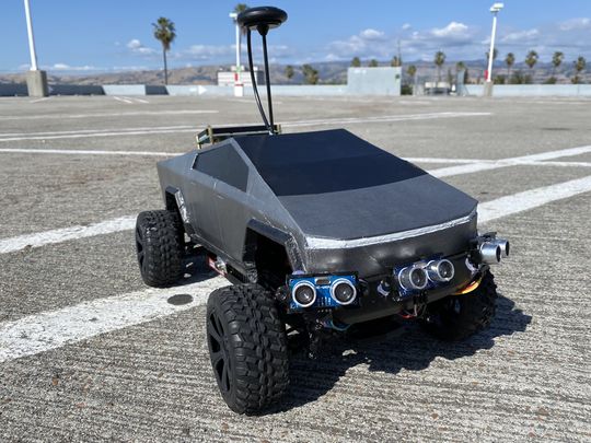
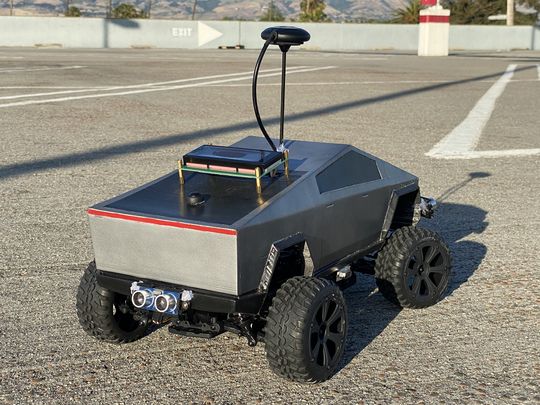
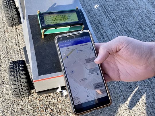
Tesla Model RC is an electric, battery-powered, self-navigating RC car. The aim is to navigate to the destination set on the Android application by utilizing GPS navigation. The car combines the data received from multiple sensors to perceive its surroundings to avoid obstacles in its path.
Introduction
The project was divided into 5 modules:
- Bridge and Sensor Controller
- Motor Controller
- Geographical Controller
- Driver and LCD controller
- Android Application
Team Members & Responsibilities
- Salvatore Nicosia Gitlab
- Motor Controller
- Geographical Controller
- System Integration and Testing
- RC Car Design: 3D Printing
- Nickolas Schiffer Gitlab
- Motor Controller
- Geographical Controller
- Architecture Design
- Danny Nuch Gitlab
- Bridge Sensor Controller
- Ayesha Siddiqua 'Gitlab
- Driver & LCD Controller
- Andrew Kwon
- Android Application
- Review Team
Schedule
| Week# | Start Date | End Date | Task | Status |
|---|---|---|---|---|
| 1 |
|
|
|
|
| 2 |
|
|
|
|
| 3 |
|
|
|
|
| 4 |
|
|
|
|
| 5 |
|
|
|
|
| 6 |
|
|
|
|
| 7 |
|
|
|
|
| 8 |
|
|
|
|
| 9 |
|
|
|
|
| 10 |
|
|
|
|
| 11 |
|
|
|
|
Parts List & Cost
| Item# | Part Desciption | Vendor | Qty | Cost |
|---|---|---|---|---|
| 1 | RC Car 1/10 Scale | Redcat Racing [1] | 1 | $99.99 + Tax |
| 2 | CAN Transceivers TJA1050 | LIVISN [2] | 5 | $6.39 + Tax |
| 3 | GPS Module Built-in Compass | Readytosky [3] | 1 | $28.89 + Tax |
| 4 | HC-SR04 Ultrasonic Module | ELEGOO [4] | 5 | $9.98 + Tax |
| 5 | HC-020K Wheel Encoder Module | Hilitchi [5] | 1 | $9.99 + Tax |
| 6 | ESP8266 WiFi Module | DIYmall [6] | 1 | $6.55 + Tax |
| 7 | Extra 7.2V 5000mAh NiMH battery | Melasta [7] | 1 | $29.99 + Tax |
| 8 | Micro-USB to USB cable | Walmart [8] | 4 | $4.00 + Tax |
| 9 | EL-CP-004 120pcs Multicolored Dupont Wire | ELEGOO [9] | 1 pack | $6.98 + Tax |
| 10 | SJTwo Microcontroller | SCE at SJSU [10] | 4 | $160 |
| 11 | Black PLA Filament | Hatchbox [11] | 1 | $22.99 + Tax |
| 12 | 120 Ω Resistor | Excess Solutions | 2 | $0.30 |
| 13 | 1 MΩ Resistor | Excess Solutions | 1 | $0.15 |
| 13 | 100 kΩ Resistor | Excess Solutions | 1 | $0.15 |
| 14 | DB9 Female Connector Right Angle Mount | Excess Solutions | 1 | $0.30 |
| 15 | 2.54 Male Header Strip 36 Pin | Excess Solutions [12] | 1 | $0.36 |
| 16 | 5x7cm Prototype Board | uxcell [13] | 3 | $7.09 + Tax |
| 17 | 2.54mm JST-XHP 2 Pin Housing with 2.54mm JST XH Female Connector | QLOUNI [14] | 8 | |
| 18 | 12mm Waterproof Push Button Momentary On Off Switch | PP-NEST [15] | 1 | |
| 19 | #22 Gauge Wire | Elenco [16] | As needed | $22.55 + Tax |
| 20 | LM2596 Buck Converter DC to DC | D-PLANET [17] | 1 | $5.95 + Tax |
| 21 | 11 in. x 14 in. x .093 in. Acrylic Sheet | The Home Depot [18] | 1 | $6.67 + Tax |
| 22 | 20x4 LCD Display Module | LCD [19] | 1 | $29.99 |
| 23 | 6-32 Brass Motherboard Standoffs | Hantof [20] | 36 | $14.58 + Tax |
| 24 | Metallic Aluminium Spray Paint | Walmart [21] | 1 | $3.96 + Tax |
| 25 | Metallic Dark Metal Spray Paint | Walmart [22] | 1 | $4.96 + Tax |
| 26 | Plastidip Black Spray Paint | Walmart [23] | 1 | $5.82 + Tax |
| 27 | Total | $533.68 |
Circuit Boards
Two circuit boards were designed to reduce the amount of wires and the necessity to use external power banks to deliver power to various modules. Both boards use #22 gauge wire which provides sufficient current flow to all the modules. The CAN board schematic shown below groups all the CAN transceivers in a single place so that the +5V power is shared among the CAN transceivers and are all close to the CAN bus. The power delivery board schematic shows how the power is taken from the main battery of the RC car and goes through a DC-DC buck converter to reduce the voltage to +5V from +7.2V. The +5V output of the buck converter delivers power to the CAN board, four SJTwo boards, 5 ultrasonic sensors, and wheel encoder. The output of the ESC in addition to powering the motor also powers the servo. Lastly, the power delivery board has a voltage reading point to monitor the voltage of the battery which is connected to the bridge sensor node.
Below are the two boards assembled. The CAN Bus board uses two 120Ω termination resistors, 2.54mm male headers to connect CAN Tx and CAN Rx of each SJTwo boards, and connected a DB9 connector on the bus to monitor and debug the state of the car through busmaster.
The power deliver board uses 2.54mm male headers for easier connection to the various modules and 4 JST 2-pin female connector to connect the micro USB cables that power the SJTwo boards.
Integrated System
In the picture shown below, is the integrated system connected to the SJTwo boards, CAN board, power deliver board, wheel encoder, motor, servo, GPS / Compass, and ultrasonic sensors. The WiFi module is directly placed on the dedicated pins of the SJTwo board of the bridge sensor node.
3D Printed Parts
Cybertruck 3D Model
This 3D model was modified and rescaled to fit the chassis of our car. Credit goes to the designer of the model which can be found on thingiverse at this link. The shell was sliced into 6 parts to fit the building plate of the printer and make it easier to print the parts with minimal supports. Shown below are pictures of the 3D model as well as the printed and finished result of the shell.
Shell Supports
These supports were designed to allow the shell to sit in place on the chassis by using 6 small magnets for each of the four corners. 4 magnets are inserted in each of these supports and 2 are attached in each corner to the plexiglass surface where the boards are mounted.
Ultrasonic Sensor Supports
The ultrasonic support 3D model was slightly resized to fit the HC-SR04 sensor. Credit goes to the designer of the model which can be found on thigiverse at this link.
CAN Communication
| Frequency | Message/Function | Message/Function | Message/Function | Message/Function | Message/Function | Message/Function | Message/Function |
|---|---|---|---|---|---|---|---|
| 1Hz | Debug info | Handle CAN bus Off | - | - | - | - | - |
| 10Hz | Handle WiFi Messages (GPS, start/stop states) | Handle MIA Messages | Handle GPS Coordinates | Handle Motor & Steering Commands | Handle Bridge Node Info (Battery Readings) | Handle Compass heading & GPS bearing | Handle Ranging Averaged Readings (front, left, right, back) |
- Bridge-sensor node
- Receives destination coordinates from android app and sends them over CAN to geographical node
- Receives vehicle navigation states from android app and sends them over CAN to driver node
- Sends ultrasonic sensors reading to driver node
- Sends battery voltage reading to driver node
- Driver node
- Sends speed and steering angle to motor node
- Geographical node
- Receives destination coordinates from bridge-sensor node
- Sends compass heading and gps bearing to driver node
- Sends distance to destination to driver node
- Motor Node
- Receives speed and steering messages from driver node
- Sends car's actual speed to driver and bridge-sensor node.
Hardware Design
DBC File
https://gitlab.com/tesla-model-rc/sjtwo-c/-/blob/dev/dbc/tesla_model_rc.dbc
Bridge Sensor ECU
https://gitlab.com/tesla-model-rc/sjtwo-c/-/tree/dev/projects/sensor

https://gitlab.com/tesla-model-rc/esp8266-coap-server
Hardware Design
| SJTwo Board | Module | Description | Protocol/Bus |
|---|---|---|---|
| P4.28 (TX3) | RX (ESP8266) | ESP8266 Rx data line | UART 3 |
| P4.29 (RX3) | TX (ESP8266) | ESP8266 Tx data line | UART 3 |
| P0.6 | Trigger (Ultrasonic) | Front sensor | |
| P2.0 | Echo (Ultrasonic) | Front sensor | |
| P0.7 | Trigger (Ultrasonic) | Rear sensor | |
| P2.1 | Echo (Ultrasonic) | Rear sensor | |
| P0.8 | Trigger (Ultrasonic) | Left sensor | |
| P2.2 | Echo (Ultrasonic) | Left sensor | |
| P0.9 | Trigger (Ultrasonic) | Right sensor | |
| P2.4 | Echo (Ultrasonic) | Right sensor | |
| P0.25 (ADC2) | Voltage reading (S) | Output of voltage divider | |
| P0.1 (SCL1) | CAN transceiver (Tx) | CAN transmit | CAN |
| P0.0 (SDA1) | CAN transceiver (Rx) | CAN receive | CAN |
| 5V (Ultrasonics) | Vcc | ||
| GND | GND | Ground |
Software Design
Bridge and Sensor Node
The Bridge and Sensor node interfaces with four ultrasonic sensors (front, back, left, and right) and the ESP8266 Wifi module for bridging connection with a mobile application to control the car and display ultrasonic ranging diagnostics.
Sensor Node and CAN Bus Periodics Handler module
The CAN bus handler has periodicially running functions specific to a task and is called in the Periodics module. Debug messages that may be enabled are sent at 1Hz. The handler of all incoming messages (including Wifi messages) is parsed in 10Hz, along with MIA management and the transmission of CAN messages. Unique to this node is the 100Hz functions that initiates and records Ultrasonic sensor rangings at this rate along with the Wifi character parser which fills the message buffer. This module wraps the Sensor Node module.
The Sensor Node module creates the sensing messages that are sent over the CAN bus. These messages include battery voltage level and all four ultrasonic ranging distances. Furthermore, the GPS longitude and latitude value and start/stop state changes parsed from Wifi transmissions are sent as well. This module handles MIA messages of the Driver node's heartbeat message. On not receiving the Driver node's heartbeat message, this module will not send messages over CAN bus and brighten LED0 indicating the node is not synchronized with the Driver node.
Wifi module
The Wifi module initializes UART channel 3 peripheral and the line buffer module. The line buffer module is used for parsing and handling Wifi messages transmitted over UART from the ESP8266. The Wifi line buffer has 128 bytes of allocated space and is filled at a rate of 100Hz from the UART queue. Then, at 10Hz the Wifi line buffer handler parses all lines found in the line buffer based upon the identifier found from a new-line delimited sequence of messages. These messages are specified in the ESP8266 section and set variables received from the mobile application to messages over CAN bus. The Wifi module also sends all four ultrasonic ranging values to the ESP8266 over UART allowing the mobile application to query ultrasonic diagnostics.
Battery Tracking module
The Battery Tracking module is simply an ADC that receives the battery output as input. The ADC has a voltage reference of 3.3V and has a 12 bit resolution. Thus, the ADC conversion is 3.3V / 4095. The voltage divider set for the receiving battery voltage is a divider where R1 = 1M ohm and R2 = 100k ohm. Thus, the received ADC binary representation along with the ADC conversion value and the voltage multiplier gives the current battery voltage and is sent over the CAN bus.
Ultrasonics and GPIO Interrupts module
Ultrasonic sensors are initialized where each sensor has a trigger and echo pin. A trigger pin is used to initiate ranging from activating the trigger pin for 10 microseconds then setting it back to inactive. This will release an ultrasonic wave in the air that travels at the speed of sound. The reflection of the ultrasonic wave is sampled by the echo pin until the falling edge of an interrupt occurs where the time of flight of this wave is calculated from half of the round trip time by dividing by 2 as the distance is calculated as soon as the ultrasonic wave transmits and reflects from an obstacle and the speed of sound for converting to the distance traveled. The ultrasonic ranging calculation is (where tof = time of flight and sos = speed of sound):
ranging calculation in inches = (tof / 2) * sos = tof * (13503.9 in/s / 1000000 us) / 2 = tof * 0.00675195 in = (tof / 148.105) in
Average Buffer module
Ultrasonic smoothing is done by averaging a set amount of past ultrasonic values and sending out the averaged value over the CAN bus. This averages ranges that may be invalid due to an outlier. Ranges are collected at a 100Hz rate and are sent over CAN bus through a 10Hz function using a 10 slot sliding window average buffer where this buffer will be filled before the message is sent over CAN bus. A low-pass filter is implemented where zeroed values are replaced with the average value from the sliding window buffer. Zeroed ranges is a special case where a sensor receives ultrasonic waves immediately after the start of a trigger caused by scattered reflection of other ultrasonic waves in the air.
ESP8266
Bridging between ESP8266 and mobile application is done through the creation of an access point on the ESP8266. Furthermore, the ESP8266 opens a server socket through the Constrained Application Protocol (CoAP) allowing other CoAP clients to transmit or receive data from a created resource (/topics). The mobile application serves as the CoAP client and currently performs:
(GET) /heartbeat will receive string: "tmrc:heartbeat"

(GET) /getRadars will receive string: "aa,bb,cc,dd" where a is front radar, b is left radar, c is right radar, and d is back radar

(PUT) /setStatus will send string - either "$stop\n" or "$start\n"

(PUT) /setCoordinates will send coordinates as string - i.e. "#Sxxx.xxxxxx,Syyy.yyyyyy\n" where S is the sign and x is latitude and y is longitude
/getRadars resource will update through UART from a microcontroller. The string must follow the format: "^%02,%02,%02,%02" where '^' is the identifier for setting this resource. This length is also fixed where each radar data must have a width of no more than 2.
/setStatus resource has an identifier of '$', while /setCoordinates resource has an identifier of '#'. Both resources require appending a new line character at the end of string. This is essential for parsing strings on microcontroller side as the ESP8266 echoes received data over UART.
Project Setup
This project is built with ESP8266 RTOS SDK for programming the ESP8266. FreeRTOS, UART, Wifi with CoAP libraries are fully utilized in this project.
See the Getting Started Guide from this SDK for full steps to configure and use ESP-IDF to build projects.
Wifi Access Point module
ESP8266 opens an access point for other wireless devices to connect too. This access point follows adaptation of this example:
https://github.com/espressif/ESP8266_RTOS_SDK/tree/master/examples/wifi/getting_started/softAP.
UART Configuration module
UART is simply transmitted over UART0 TX/RX pins. This example is integrated:
https://github.com/espressif/ESP8266_RTOS_SDK/tree/master/examples/peripherals/uart_events
CoAP Server module
CoAP server would startup a daemon task, create resources and receive data from CoAP clients and transmit data to CoAP clients. This server follows adaptation of a couple examples:
https://github.com/espressif/ESP8266_RTOS_SDK/tree/master/examples/protocols/coap_server

https://github.com/obgm/libcoap-minimal/blob/master/server.cc

https://github.com/obgm/libcoap/blob/develop/examples/coap-server.c
The Constrained Application Protocol (CoAP) is a specialized web transfer protocol for use with constrained nodes and constrained networks in the Internet of Things. The protocol is designed for machine-to-machine (M2M) applications such as smart energy and building automation. Please refer to RFC7252 document for more details.
Technical Challenges
Ultrasonic Sensors Smoothing and Filtering
The average buffer module had to be implemented as ultrasonics ranging values from a fixed distance had varying values. The average buffer module smoothed out ranging values by using an average sliding window of the last 10 ranges as the value sent over the CAN bus. In parallel to this average buffer, a low-pass filter is implemented where a value of zero would be replaced by the average of the sliding window buffer. This further smoothed the ultrasonic ranges by removing values that occurred upon reception of a radar wave right after a range is initiated through the trigger pin.
ESP8266 Flashing
When flashing the ESP8266 be extremely observant about which mode the SPI should be configured. Different vendors will have SPI flash modes.
Motor ECU
https://gitlab.com/tesla-model-rc/sjtwo-c/-/tree/dev/projects/motor_node
Hardware Design
| SJTwo Board | Module | Description | Protocol/Bus |
|---|---|---|---|
| P2.0 (PWM1) | Motor (S) | Control signal for motor speed | |
| P2.4 (PWM5) | Servo (S) | Control signal for servo steering | |
| P0.22 (PWM1) | Wheel encoder (Out) | Output signal of wheel encoder | |
| P0.1 (SCL1) | CAN transceiver (Tx) | CAN transmit | CAN |
| P0.0 (SDA1) | CAN transceiver (Rx) | CAN receive | CAN |
| 6V Motor and Servo | Vcc | ||
| 5V Wheel encoder | Vcc | ||
| GND | GND | Ground |
Wheel Encoder
The wheel encoder provides speed reading of the car by tracking the number of revolutions the disk makes through the reflection of the infrared light emitted by the sensor. This sensor was used to allow the car to go at constant speed when going uphill, downhill, or spots where the speed is reduced.
Software Design
The main goal of the motor control node is to receive a requested speed and steering angle from the driver node and adjust the motor and steering angle accordingly such that those requested values are reached.
Upon calling motor_control__initialize(), the node initializes the necessary GPIO pins that are used to control the motor and steering servo. Additionally, it enables and attaches an interrupt to the pin that the wheel encoder is attached to. This directs the interrupts to trigger a callback that increments a count of rotor ticks which will later be used to calculate speed.
At this point, the run_once() function will begin to be called at 10Hz or every 100ms. The run_once() function calls the following functions: motor_control__handle_steering(), motor_control__private_handle_rotor(), and motor_control__handle_speed().
motor_control__handle_steering() simply maps the requested steering angle to a usable PWM value between the experimentally derived lower and upper PWM bounds for left and right.
motor_control__private_handle_rotor()'s goal is to take the rotor tick counts since the last call, and calculate the average speed of the car over the last 100ms. It does this by following some simple geometry as shown:
   const float distance_traveled_since_last_checkin_meters = ((float)rotor_tick_count / ticks_per_rotation) * wheel_circumference_cm / 100.0f;
   const float average_speed_meters_per_second = distance_traveled_since_last_checkin_meters / ((float)time_elapsed_since_last_checkin_ms / 1000.0f);
   const float average_speed_kilometers_per_hour = average_speed_meters_per_second * 3.6f;
   // Deadlock Empire :)
   gpiolab__disable_interrupts();
   rotor_tick_count = 0U;
   gpiolab__enable_interrupts();
   latest_calculated_ground_speed_km_per_hour = average_speed_kilometers_per_hour;
   motor_control__private_send_current_speed();
First, the distance_traveled_since_last_checkin_meters is calculated based on how many ticks equal a wheel rotation, and the circumference of the car's wheel converted to meters. Once this is calculated, the average speed in meters per second can be derived from dividing the distance in meters by time in seconds. Next, to convert from meters per second to kilometers per hour, a simple conversion factor of 3.6 is used.
Once the average speed is found, the rotor_tick_count needs to be set back to 0 for the next round. Because that variable is being updated in an interrupt context, we need to temporarily disable the interrupts to this variable being updated by the interrupt and this function at the same time.
motor_control__handle_speed() utilizes a state machine to control the motor. This is because controlling the motor is very context-dependent and requires specifically timed control sequences to function properly. The states are as follows:
 typedef enum {
   SPEED_CONTROL_STATE__ESC_ARM_INITIALIZE = 0,
   SPEED_CONTROL_STATE__ESC_ARM_WAIT_STATE,
   SPEED_CONTROL_STATE__STOPPED,
   SPEED_CONTROL_STATE__FORWARD,
   SPEED_CONTROL_STATE__TRANSITION_TO_REVERSE_0,
   SPEED_CONTROL_STATE__TRANSITION_TO_REVERSE_1,
   SPEED_CONTROL_STATE__REVERSE
 } motor_control__speed_control_states_e;
- The SPEED_CONTROL_STATE__ESC_ARM_INITIALIZE and SPEED_CONTROL_STATE__ESC_ARM_WAIT_STATE are the first states of the state machine. They are used to comply with the start-up/self-test sequence of the ESC that controls the motor. In these states, we must hold the throttle in the neutral position for around 3 seconds. After this time, the ESC will beep, indicating that its start-up/self-test sequence has completed. If this beep does not occur, the motor will not move.
- The next state is SPEED_CONTROL_STATE__STOPPED. In this state, the neutral throttle PWM value is sent to the ESC which causes the motor to stop. Depending on the requested speed in this state, the next state will change to SPEED_CONTROL_STATE__FORWARD or SPEED_CONTROL_STATE__TRANSITION_TO_REVERSE_0.
- The SPEED_CONTROL_STATE__FORWARD state is entered when the requested value from the driver node is above the forward threshold. The state machine enters this state from the SPEED_CONTROL_STATE__STOPPED state. In this state, the requested speed is compared to the current speed. Every 100ms iteration, (assuming the requested direction stays forward), there is logic to dynamically adjust the PWM value sent to the ESC to speed up or slow down to car. If the requested speed falls below the forward threshold, the state machine will re-enter the SPEED_CONTROL_STATE__STOPPED state.
- The SPEED_CONTROL_STATE__TRANSITION_TO_REVERSE_0 is entered from the SPEED_CONTROL_STATE__STOPPED state if the requested speed is below the reverse threshold. Transitioning to reverse requires a carefully timed sequence of inputs to change the directional mode of the ESC. First, the PWM values are set to a reverse value in SPEED_CONTROL_STATE__STOPPED. Next, SPEED_CONTROL_STATE__TRANSITION_TO_REVERSE_0 will adjust the PWM values to the neutral position for 2 iterations (200ms). The the state is set to SPEED_CONTROL_STATE__TRANSITION_TO_REVERSE_1.
- The SPEED_CONTROL_STATE__TRANSITION_TO_REVERSE_1 sets the PWM value back into reverse for another 2 iterations (200ms). Once this state completes, the car will be able to reverse, otherwise, giving reverse throttle applies an electronic braking effect.
- The SPEED_CONTROL_STATE__REVERSE state works similarly to the SPEED_CONTROL_STATE__FORWARD state. It will first negate the current speed. This is because the rotor_encoder cannot determine which direction the wheels are turning, only the magnitude of the speed. Then, it will compare this value with the current requested speed and will adjust the PWM value each iteration to increase or decrease the throttle to achieve/maintain the requested speed. If the requested speed goes above the reverse threshold, it will then back into the SPEED_CONTROL_STATE__STOPPED state.
Technical Challenges
Throughout the development of this node there were many technical challenges. Some related to undocumented functionality, others due to physical construction constraints.
- ESC Self-Test/Start-up sequence: The ESC (Electronic Speed Controller) for our car does not allow the wheels to turn unless the startup sequence has been performed. Unfortunately since our car came as a kit, there was no documentation available for the ESC. While connected to the included remote control, we attached oscilloscope probes to the pwm pins between the receiver and ESC. We then set up a capture to observe the signals upon startup. With some trial and error, we were able to program a sequence that allowed the ESC to pass this stage as described above in the Software Design.
- ESC Reverse Mode: While prototyping reverse functionality, we quickly realized that simply sending lower pwm values to the ESC would not make the car reverse. Again, using the included remote control allowed us to troubleshoot and solve the problem. This ESC (and many others in the hobby-electronics world) utilize a behavior that prevents the user from transition directly from forward to reverse. This is to both save the motor from unintentional damage from reversing while at a high speed, and also allows for the braking functionality. While using the included remote control we realized that to get into reverse from forward, one must transition from forward to reverse, back to neutral, and then back to reverse. These transitions also have to have take place over a certain time interval. Therefore, these states are visited multiple times within the state machine in order to hold these positions for a long enough amount of time.
Geographical ECU
https://gitlab.com/tesla-model-rc/sjtwo-c/-/tree/dev/projects/geo_node
Hardware Design
The geographical controller is interfaced to the readytosky GPS with built-in compass and a CAN transceiver as shown in the figure below. The readytosky module uses the Ublox NEO-M8N GPS which provides great accuracy and customization. In addition, it uses the 3-Axis compass HMC5883L magnetometer which provides a 1 to 2 degrees compass heading accuracy. The Ublox GPS module communicates with the SJTwo board via UART whereas the HMC5883L communicates with the SJTwo board via I2C. The CAN transceiver is interfaced to the CAN Bus and allows reception and sending of CAN messages via the CAN pins on the SJTwo board. When the driver node goes MIA the geographical controller lights an LED indicating the MIA status of the node.
| SJTwo Board | GPS/Compass Module | Description | Protocol/Bus |
|---|---|---|---|
| P4.28 (TX3) | RX (Yellow Wire) | Ublox M8N Rx data line | UART 3 |
| P4.29 (RX3) | TX (Green Wire) | Ublox M8N Tx data line | UART 3 |
| P0.10 (SDA2) | SDA (White wire) | HCM5883L SDA | I2C 2 |
| P0.10 (SCL2) | SCL (Orange wire) | HCM5883L SCL | I2C 2 |
| P0.1 (SCL1) | CAN transceiver (Tx) | CAN transmit | CAN |
| P0.0 (SDA1) | CAN transceiver (Rx) | CAN receive | CAN |
| Vcc 3.3V | Vcc (Red wire) | Vcc | |
| GND | GND (Black wire) | Ground |
Software Design
Overview
The geographical node calls periodically the following code modules:
- gps.c
- compass.c
- checkpoint.c
- geological.c
- can_bus_message_handler.c
These modules, calculate compass heading degree, bearing, parse GPS coordinates, calculate the checkpoints the RC car has to go through when navigating to a destination, send distance to destination to driver node, and handle messages received on the CAN bus.
- The period_callbacks__initialize() function calls the following functions:
- can_bus_initializer__init(): initializes the CAN bus to handle MIA and messages.
- geological__init(): initializes the GPS, compass, and checkpoint algorithm.
- The period_callbacks__1Hz() function calls the following function:
- can_bus_initializer__handle_bus_off()
- The period_callbacks__10Hz() function calls the following functions:
- can_bus_message_handler__manage_mia_10Hz() to manage MIA signals.
- can_bus_meesage_handler__handle_all_incoming_messages_10Hz() to handle messages on the CAN bus (e.g. destination coordinates from Bridge sensor node).
GPS
Initialization
In the initialization process of the GPS, the line buffer module is configured to parse the GPS messages, the GPIOs P4.28(Tx) and P4.29(Rx) are configured, UART interrupt queues enabled, and the UART is configured at a baudrate of 9600.
Configuration
In the gps__run_once_10Hz() the GPS is initially configured once to disable all NMEA messages except GNGGA which is message chosen to parse the coordinates and GPS lock.
Parsing NMEA GNGGA messages
The GPS module constantly transmits NMEA GNGGA messages over UART to the SJTwo MCU. These messages which come in the form of a string are stored character by character in the line buffer until a new line character which indicates the end of string. The stored string is then extracted from the line buffer and the checksum is verified to ensure that the message is not corrupted. The extracted line is then tokenized to parse the latitude, latitude direction, longitude, longitude direction, and fix quality. South and West directions are also properly handled to make the latitude and longitude negative values.
GPS lock
The GPS lock is a function in the gps.c module that has the job to set a bool flag and blink an LED when the fix quality is either 1 or 2 in the GNGGA message. When the fix quality is one of those values it means the GPS has acquired a good connection to the satellites and the data received is valid. The LED blinking functionality was used for debugging purposes indicating the GPS has a lock. Whereas the bool flag was used as a condition to calculate the bearing and checkpoints only when the GPS had a lock meaning that the current coordinates were valid.
Compass
Initialization
The compass initialization configures the HMC5883L magnetometer registers over I2C bus to default settings using a gain of 1090 and single mode.
Heading degree computation
The compass heading degree is computed by using the tilt compensation algorithm and the pitch and roll values calculated from the SJTwo accelerometer. The tilt compensation algorithm ensures that the values of the compass heading are precise within an error of 1 to 2 degrees when the compass is tilted in all directions. Shown below are the formulas used to compute the heading degree referenced from this link.
Pitch and Roll:
pitch = asin(-accelerometer_x_axis)

roll = asin(accelerometer_y_axis / cos(pitch)
Tilt compensated magnetic sensor values for x and y:
Mx_c = (Mx - offset_x_axis) * cos(pitch) + Mz * sin(pitch)

My_c = (Mx - offset_x_axis) * sin(roll) * sin(pitch) + (My - offset_y) * cos(roll) - Mz * sin(roll) cos(pitch)
- where:
- Mx_c = Magnetometer x-axis tilt compensated
- My_c = Magnetometer y-axis tilt compensated
- Mx = Magnetometer x-axis value
- My = Magnetometer y-axis value
- Mz = Magnetometer z-axis value
The offset values for x and y are calculated during calibration to reduce soft-iron and hard-iron distortions. Soft-iron distortions are generally caused by nearby metals such nickel and iron in which distorts the existing magnetic field of the compass depending in which direction the field acts. Hard-iron distortions are produced by objects that generate a magnetic field such as the motor of the RC car causing a permanent bias in the compass sensor if not corrected.
To calculate the scale factors for x and y to reduce soft-iron distortions the following equations were used:
a = (max_y - min_y) / (max_x - min_x)

b = (max_x - min_x) / (max_y - min_y)
x_scale = a > 1.0 ? a : 1.0;

y_scale = b > 1.0 ? b : 1.0;
To calculate the offset for x and y to reduce hard-iron distortions the following equations were used:
offset_x = ((max_x + min_x) / 2.0) * x_scale

offset_y = ((max_y + min_y) / 2.0) * y_scale
Heading angle
heading = azimuth = atan2(magnetometer_x_axis / magnetomer_y_axis) - π + 0.23
To the heading is also added the declination angle which is based on location and in our case it is 0.23. This heading is calculated in radians since atan2 returns a value between -π and +π. Therefore, before converting the heading into degrees the value needs to be normalized to put it in the range from 0 to 360 degrees.
Geological.c module
Initialization
The geological.c module initializes the gps and compass with the configurations explained before.
Run once at 10Hz
Every 10Hz the geological_run_once() function periodically calls the gps module, gets the parsed coordinates, gets the compass heading degree, sets the current and destination coordinates, sends the calculated bearing degree over CAN to the driver node, and runs the checkpoint algorithm.
Bearing Angle computation
The bearing which is the angle towards our desired destination is computed using the formulas below referenced at this link.
X = cos θb * sin ∆L
Y = cos θa * sin θb – sin θa * cos θb * cos ∆L
β = atan2(X,Y)
- where:
- θa = current latitude
- θb = destination latitude
- ∆L = destination longitude - current longitude
- β = heading degree in radians
The bearing is also calculated in radians since atan2 returns a value between -π and +π. Therefore, before converting the heading into degrees the value needs to be normalized to put it in the range from 0 to 360 degrees. The calculated bearing is then sent to the driver node which use the compass heading degree and the bearing to align the car toward the target destination.
Checkpoints Algorithm
The checkpoint algorithm depicted below uses a simple algorithm in which chooses the next point to navigate to if the checkpoint is the closest to the car while at the same time the closest to the destination. For the testing of our car navigation system, we choose the top floor of the north garage at San Jose State University as it provides a great open space and best signal for the GPS. In the figure shown below, five checkpoints were chosen in which the car can navigate to depending on where the destination is set to. Having fewer points rather then having too many reduces the amount of checkpoints the car has to move to and allows to reach the destination quicker while at the same time avoid areas such as the ramp in which the car should not go to.
To calculate the geographical distance between the two points the haversine formula was used which is called periodically from the checkpoint.c module. Below is the formula used:
a = sin²(ΔlatDifference/2) + cos(lat1) * cos(lt2) * sin²(ΔlonDifference/2)
c = 2 * atan2(sqrt(a), sqrt(1−a))
d = R * c
- where:
- ΔlatDifference = latitude 2 - latitude 1 (difference of latitude)
- ΔlonDifference = longitude 2 - longitude 1 (difference of longitude)
- R = 6371000.0 meters = radius of earth
- d = distance computed between two points
- a and c are intermediate steps
CAN messages
The geographical node periodically handles all incoming messages at 10Hz. The following messages are received by the geographical node to set the destination and allow the computation of the bearing and checkpoints:
BO_ 106 BRIDGE_SENSOR_GPS_HEADINGS: 8 BRIDGE_SENSOR
 SG_ BRIDGE_SENSOR_GPS_HEADINGS_LONGITUDE : 0|32@1- (0.000001, 0) [0|2000] "degrees" GEO, DRIVER
 SG_ BRIDGE_SENSOR_GPS_HEADINGS_LATITUDE : 32|32@1- (0.000001, 0) [0|2000] "degrees" GEO, DRIVER
The geographical node periodically all sends messages at 10Hz. The following messages are sent by the geographical node:
BO_ 105 GEO_GPS_COMPASS_HEADINGS: 8 GEO
 SG_ GEO_GPS_COMPASS_HEADINGS_CURRENT : 0|32@1- (0.000001,0) [0|360] "degrees" DRIVER, BRIDGE_SENSOR
 SG_ GEO_GPS_COMPASS_HEADINGS_DESTINATION : 32|32@1- (0.000001,0) [0|360] "degrees" DRIVER, BRIDGE_SENSOR
BO_ 117 GEO_GPS_DISTANCE: 4 GEO
 SG_ GEO_GPS_DISTANCE_TO_DESTINATION : 0|32@1- (0.000001,0) [0|0] "meters" DRIVER, BRIDGE_SENSOR
Technical Challenges
GPS (Ublox Neo-M8N)
- Problem:The enabled 2-stop bits in uart.c were causing communication problems between the SJTwo MCU and the Ublox M8N GPS module.
- Solution:To solve the issue the 2 stop bits configuration was disabled in uart.c in the uart__init() function as shown in the figure below.
- Problem:GPS module did not retain configurations and were lost after being powered off for many hours going back back to default settings. This problem was crucial since it was causing the SJ2 to parse the latitude and longitude incorrectly from other messages other than NMEA GNGGA.
- Solution: To solve this configuration problem u-center which is an interface for the GPS Ublox module was used to read which strings the program sends over UART to configure the GPS module. This solution was implemented in the gps.c module creating a function called gps__private_configure_for_nmea_gngga() in which holds a char array with the hex representation of the configurations needed to disable all of the NMEA messages except GNGGA. This function then sends this configuration values back to the GPS module over UART and the GPS module responds back with an ACK message (8μ.......) from every configuration message meaning that the configurations were successfully applied as shown in the figure below. The function gps__private_configure_for_nmea_gngga() could not be called in the periodic_callbacks__initialize() function has it required more time to properly configure the GPS. As a solution, a bool flag indicating that the configuration was done was used along with calling gps__private_configure_for_nmea_gngga() in the gps_run_once_10Hz() to allow it properly configure the GPS module.
Compass (HMC5883L 3-Axis Magnetometer)
- Problem:SJTwo MCU could not detect the slave address of the HMC5883L magnetometer on the I2C Bus 2.
- Solution:Upon reading the HMC5883L datasheet it was mentioned that it works at 400KHz. However, this was not the case as changing the speed in peripherals__init.c module from 400KHz to 100KHz solved the issue and the SJTwo board successfully detected the HMC5883L 3-Axis Magnetometer. In the figure below is shown the function a long with change it was made. In addition, changing the speed did not affect the other modules using I2C Bus 2.
- Problem:Compass heading degree true north was off by about 90 degree when compared to the compass of smart phone. This problem was due the fact the compass had to be completely flat to show proper values. In addition, the default calibration seemed also to be a problem in providing an accurate heading degree a long with hard iron and soft iron interferences.
- Solution:To solve these problems a function to calibrate the compass was implemented in which calculates offset and scale correcting for hard iron and soft iron interferences respectively. The process to calibrate consisted in turning the compass at different angles to collect as many sample points as possible and store offsets values of x and y axes in const variables which were then used in the equations to compute the heading degree. Although this corrected some of the imprecision problems, not having the compass completely flat still provided results that were not precise. To solve this issue the compass was compensated for tilt by using the built-in accelerometer of the SJTwo board which provides roll and pitch and the tilt compensation algorithm described at this link. The challenge in making this work properly was that the axes of the magnetometer and the axes of the accelerometer need to be perfectly aligned. However, after finalizing the place of the compass on the RC car it was fairly easy to align the axes. The tilt compensation system for the compass is shown in the figure below. After including the tilt compensation algorithm the compass heading degree was off by 1-2 degrees when tilted in all directions drastically improving the accuracy from non-compensated in which the heading was off by 60-90 degrees when the compass was not held flat.
- Problem:Compass heading degree was decreasing when turning clock-wise rather then increasing.
- Solution:To solve this problem, the Azimuth rather then being calculated as atan2(Y / X) was calculated as atan2(X / Y). This fixed the Azimuth orientation however, North degree was shown as 180 degrees which was incorrect. Finally to compensate for this, π was subtracted from the Azimuth = atan2(X / Y) - π to show the correct decimal degree for true North which is 0 degrees.
Driver Controller & LCD
The driver node is the heart of the designed RC car. It receives appropriate messages from the bridge-sensor node and geo node and processes the signals before sending speed and steering values to the motor node.
https://gitlab.com/tesla-model-rc/sjtwo-c/-/tree/dev/projects/driver_controller_node
Hardware Design
| SJTwo Board | LCD Module | Description | Protocol/Bus |
|---|---|---|---|
| P4.28 (TX3) | RX | LCD Rx data line | UART 3 |
| P4.29 (RX3) | TX | LCD Tx data line | UART 3 |
| P0.15 | +Vcc Button | Button + | |
| P0.1 (SCL1) | CAN transceiver (Tx) | CAN transmit | CAN |
| P0.0 (SDA1) | CAN transceiver (Rx) | CAN receive | CAN |
| Vcc 3.3V | Vcc (Red wire) | Vcc | |
| GND | GND (Black wire) | Ground |
Software Design
- LCD display
- The LCD is used to display a few important signal values, which will help us monitor the car behavior when it's moving.
- The communication with LCD is established using UART.
- We have used a 20x4 LCD whose behavior was to print individual lines at a time.
- Twoscreens were designed for the LCD depending on the state of the car.
- The first screen displayed all node heartbeat values. The car will wait on this screen if any one of the node heartbeats is zero.
- The second screen displayed information from the multiple sensors.
- The first line of the second screen has the front, right, left and back sensor information received from the sensor node
- The second line has compass heading received from the geo node, the internal state of the driver state machine, and the checkpoint number.
- The second line has speed and steering values sent to the motor node from the driver node.
- The fourth line of the second screen has destination distance and heading received from the geo node.
- Navigation state machine
- The car navigation is achieved with the help of a state machine.
- The main states of the state machine are INIT, WAIT, OBSTACLE, and NAVIGATE.
- The car waits in the INIT state till all the nodes provide the heartbeat.
- The WAIT state has multiple components in it. The test button is added to the WAIT state. The car is in the WAIT state till a start signal is received from the mobile application.
- When the start signal is received from the app the enters the OBSTACLE state.
- The obstacle avoidance algorithm is simple. If there is no obstacle reported by the sensors then the car enters the NAVIGATE state.
- If an obstacle is detected then another state machine is started which finds out the obstacle placement and the motor speed and steer values.
- The below flowchart shows the obstacle avoidance algorithm.
- If no obstacle is detected then another state machine is started which finds out the correct navigation steering and the motor speed.
- The navigation is calculated based on the destination and heading angle.
- Care is also taken if the angles are greater than 180 degrees.
- The below flowchart shows the navigation algorithm.
Technical Challenges
- The initial reverse functionality worked when an obstacle was detected in front of all the sensors. This was causing problems when the car has no room to turn hard right and left.
- This reverse functionality was improvised if any two sensors read values less than the minimum turning distance.
- A stop state was added in the motor node for reverse functionality but still issues were encountered during testing.
- Stop state was also added in the reverse functionality along with delay in the reverse sate.
- To change the obstacle detection after taking a reverse initial process was to construct another state machine.
- Addition of simple hard right steer movement solved the issue.
Mobile Application
https://gitlab.com/tesla-model-rc/mobile-app-CoAP-client
Application Communication
Our App communicates with the Bridge/Sensor node through WiFi using the Constrained Application Protocol (CoAP). CoAP protocol has the benefits of transmitting smaller message packets since its underlying transport is UDP. CoAP works extremely well for point to point communication and doesn't require the full feature sets from TCP transportation.
Because our App was written in Java, requirements were set such that the CoAP library to be imported must also be written in Java to be compatible with the App. After days of research we found several Java candidates of this protocol. Californium is a library that is constantly being updated and has the most documentation and most active community. WS4D was also a strong candidate because of its simple interface design. We chose WS4D over Californium because WS4D provides an interface for a CoAP Client that gave us the most flexibility on how we connect to end points and send/receive data.
Pros and Cons
- The ESP8266 WiFi module was able to communicate with the App over very long distances. We were able to send POST messages from approximately 50 meters away. However power consumption on the App from the frequent message requests were draining the battery on the phone faster than normal. Bluetooth and Bluetooth LE has the advantage of being able to drain less power and run for longer periods of time on the App as well as the RC car.
- The length of the payload, or response to a GET request, has a maximum length of 16 bits. Any string data before being decoded, must fit this requirement. If a message fails to reach its destined end point, CoAP protocol will attempt to resend the message three times, before sending a failure response. One problem that arose was sending GET requests without verifying connection to the ESP8266 server. The buffer of unsent messages overflowed causing the Bridge node to receive unintentional error messages.
- Connecting to the WiFi Server was extremely easy. The network SSID and WPA2 key were hard coded parameters supplied to WifiManager object. You could also save the network on your phone as you would with your home WiFi. All the user would have to do is enable WiFi, since on start up, the app will disable current WiFi connections. If the auto-connect option for the network is checked, you would be able to instantly connect to the 'tesla_model_rc' access point.
One cool feature was that up to 3 phones could connect to the car at the same time and each send "start","stop", or send GPS coordinates.
Application Design
Three fragments were created. Main Fragment, Sensor Fragment, and Map Fragment. The Sensor and Map fragment were embedded inside the Main Fragment. The design decision behind this was so that the Main fragment could easily access any layout resource defined in the .xml files of the Map fragment and Sensor Fragment. A TabLayout was used to switch between the Map fragment and Sensor Fragment. Each fragment had an Activity associated with its respective fragment. In the background, a Service is running. A Service must be bound to an application, in our case it was bound to the MainActivity and starts running when the app is opened. Its sole function is to obtain the CoAP Client instance and send GET requests to the /getRadars resource and /heartbeat resource at a frequency of 10hz.
Software Design
Technical Challenges
- The main challenges I had were not realizing the difference between a Fragment and an Activity. I had created my Fragments without realizing they needed to exist within an Activity, so when my onClick methods for buttons weren't registering, it was because there was no underlying Activity attached with the Fragment. I would suggest to have a getInstance method for all the Fragments so that different Fragments can access or call different methods.
- I also had a problem with the Progress bars not updating based off the sensor values from the Sensor node. Solution was to update the Progress bars inside a handler that accessed the main UI thread.
- There was a problem with the App not functioning properly on different Android Devices. Some buttons would not show up. I realized there are some button attributes in the layout file that caused this bug.
- Stackoverflow will be your best friend and make sure to consider every single answer, even the ones wit 0 upvotes.
Conclusion
The Tesla Model RC project was a creative expression of our problem solving and design skills; developed during a challenging time for us personally and humanity in general. The outbreak of COVID-19, early in the semester, forced us to develop most of our project remotely and independently. It forced each member of our team to step up as leaders in their own right. Everyone had to manage their time and get their modules working, with little supervision and even less help. Clean code and unit testing became critical, as did good design and a cool temperament when things went wrong. As a team, we met expectations and developed an autonomous electric car that we are all deeply proud of. At the end of the day, our greatest strength was that all of us love what we do and love improving even more.
Our autonomous electric car was (obviously) inspired by Tesla's Cybertruck. The chassis itself was our tribute to the Cybertruck and to the electric vehicle industry. Integrating all modules, using CANbus, alleviated our concerns regarding signal integrity, the same way it did for Ford, BMW and Tesla. Writing the D.B.C file gave us a deep understanding of how CAN messages are composed and transmitted between the car's modules. Developing and integrating the Android mobile application educated us on wireless communication and the various tradeoffs between Wi-Fi, Bluetooth and Bluetooth Low Energy. Integrating all of our sensors and modules proved challenging, due to the limited time we had to meet up, but our car performed well when completed.
This semester was one of the richest learning experiences we have ever had. A truly practical graduate level project that we feel Elon Musk himself would appreciate. Thanks to Preet, Aakash, and Vignesh for all of their hard work this semester and to our classmates for sharing this experience with us. At the end of the day, these are hard times but not end times and we can all look forward to an electric future.
Project Video
Project Source Code
- Git Project Link: Tesla Model RC
Advise for Future Students
- Before even touching any Android Studio code, read the following documents:
- If the App requires a periodic task such as sending GET requests, I recommend to use a Service. It doesn't instantiate a new thread and runs off the main thread.
- You can verify that you can query POST/GET messages by creating a Server on the main thread and a Client on another thread within the same App. On the main thread, create a resource and an arbitrary payload value for that resource. The newly created thread acting as the Client should send a GET request to the Server running on the main thread and be able to receive the arbitrary payload value. The very first time I connected to the ESP8266, communication worked perfectly because I was able to verify it beforehand.
- Just like in industry, many technical problems will arise. The underlying problems and bugs will be difficult to trace if only one person is assigned to it. Therefore it's important to have as many eyes as possible to spot these issues.
- Communication is key. Every member should know the progress of every other member. What they are working on, how they are doing, and progress updates in general. Situations where "I'm waiting for this to be done, so I can work on that" should never be an excuse to start progress on any modules. We didn't experience this on a first hand basis which is why we were able to finish all our tasks on time. We recommend twice-a-week meetings of at least 10 minutes between all group members. Be proactive and ask your teammates for advice on any implementation detail. All members should know the basic functionality of all the modules. If you think you are done with your part, you aren't. There is always room for improvements and don't stop there. Ask other members if they need assistance and lastly be a team player.
- As the deadline comes closer, chances of feeling pressure is more likely. Working in a team will always come with more than just technical problems. It is always important to address any issue at hand as soon as you can, including personal and technical challenges. I advise future students to communicate both personal and technical issues they are facing throughout the project, in order to prevent any built-up tension and problems to resolve last-minute. This goes back to the twice-a-week 10-30 minute meetings. Set a couple days of the week and stick to it. These meetings will be beneficial for keeping all members aware of the high level functionality and progress of all modules. In case some modules are developing slower than others, everyone will be able to have the opportunity to assist as a consequence of these meetings.
References
Bridge Sensor ECU
Motor ECU
- None used
Geographical ECU
- Bearing Formula
- Haversine Formula
- Float Comparison
- Compass calibration
- Compass Heading Tilt Compensated
- Magnetic declination
- Adafruit Library
- HMC5883L Arduino Library
- HMC5883L Datasheet
- Ublox NEO-M8 Datasheet
- Ublox M8 Receiver Description
Driver Controller and LCD
LCD Serial driver from rpigear
