Difference between revisions of "S14: Divine WINd"
Proj user8 (talk | contribs) (→Schedule) |
(→Project Source Code) |
||
| (101 intermediate revisions by one other user not shown) | |||
| Line 1: | Line 1: | ||
| − | |||
| − | |||
| − | |||
| − | |||
| − | |||
| − | |||
| − | |||
| − | |||
| − | |||
| − | |||
| − | |||
| − | |||
== Divine WINd == | == Divine WINd == | ||
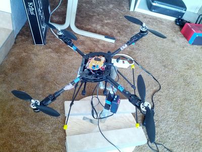
| + | [[File:Cmpe244 S14 Divine WINd Quadcopter Top View.jpg | 900px | thumb | center | Divine WINd Quadcopter with balance testing platform ]] | ||
== Abstract == | == Abstract == | ||
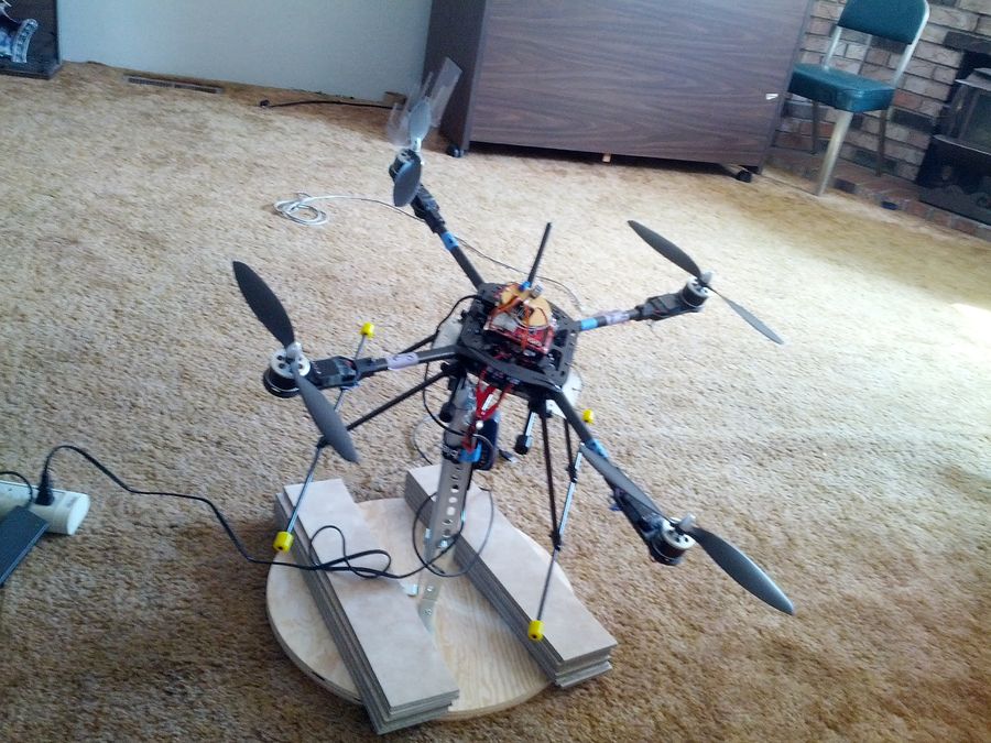
| − | + | Divine WINd is a quadcopter that focuses on stable flight and simple movement controls. There are two modules in which Divine WINd are composed of: the controller and the quadcopter. The controller module sends a signal to the quadcopter in how the quadcopter's pitch and roll orientation should be set to. The quadcopter's orientation dictates the type of movement the quadcopter will perform. | |
| + | |||
| + | In order to set to the quadcopter to its desired orientation, an accelerometer and gyrometer are implemented in order to receive the quadcopter's current orientation. The quadcopter will then adjust the speed of its fan blades to balance itself in order to be re-positioned to its the desired orientation. | ||
== Objectives & Introduction == | == Objectives & Introduction == | ||
| − | + | The project goal was to develop a control system for a quadcopter such that it can perform basic flight motions as received from a transmitting remote. | |
| + | |||
| + | *Remote Control | ||
| + | **Comprised of an SJONE board and using the Nordic Wireless to send two data packets to the quadcopter. | ||
| + | **This remote must control the speed and the motions of the quadcopter. | ||
| + | **A kill-switch must be implemented such that the quadcopter remains in a hover or dead state until disabled. | ||
| + | |||
| + | *Quadcopter Controls | ||
| + | **Receives data from the remote controller corresponding to speed and orientation. | ||
| + | **Quadcopter must stabilize and perform operations received. | ||
| + | **Quadcopter must keep a timer such that if communication is broken, it defaults to hover mode. | ||
| + | **Kill switches, when enabled, must stay in effect until disabled and Quadcopter | ||
| − | === Team Members & Responsibilities === | + | === Team Members & Primary Responsibilities === |
* Ryan Marlin | * Ryan Marlin | ||
| − | ** | + | ** Quadcopter Balance Implementation |
* Eriberto Velazquez | * Eriberto Velazquez | ||
| − | ** | + | ** Wireless Control System Implementation |
* Devin Villarosa | * Devin Villarosa | ||
| − | ** | + | ** Research and Hardware Implementation |
| + | |||
| + | == How Quadcopters Fly == | ||
| + | |||
| + | |||
| + | |||
| + | {| | ||
| + | [[File:Cmpe240 f13 quadcopter pitchrollyaw.png|Figure 1 - Roll Pitch and Yaw]] | ||
| + | |} | ||
| + | |||
| + | All flying machines has three axes of motion: Roll, Pitch, and Yaw. For this design, the quadcopter is only focused in Roll and Pitch. Roll and Pitch movements are enough for basic Quadcopter movements. | ||
| + | |||
| + | {| | ||
| + | [[File:Cmpe240 f13 quadcopter motion.png]] | ||
| + | |} | ||
| + | |||
| + | Balance is the main importance for flight. A quadcopter has four blades in which two blades spins clockwise and the other two spins counter clockwise. Each pair of blades adjusts its speed to balance out its axis. In order to perform simple movements, the quadcopter must be balanced at a particular orientation in order to move to the desired location. | ||
| + | |||
| + | == Final Parts List == | ||
| + | |||
| + | |||
| + | |||
| + | |||
| + | |||
| + | |||
| + | {| class="wikitable" | ||
| + | | align="center" style="background:#f0f0f0;"|'''Quantity''' | ||
| + | | align="center" style="background:#f0f0f0;"|'''Items''' | ||
| + | | align="center" style="background:#f0f0f0;"|'''Notes''' | ||
| + | |- | ||
| + | |align="center"|1 | ||
| + | |align="center"|Bumblebee 550 Quadcopter Kit | ||
| + | |align="center"|Kit came with 4x 20A High Speed ESC, 4x 2812 Brushless Motors 4, and 4x 10x3.8 Props. Manufacturer and part number are unidentifiable. http://www.amazon.com/Bumblebee-Quadcopter-10x3-8-Props-Motor/dp/B009P1UYBK/ref=sr_1_sc_1?s=toys-and-games&ie=UTF8&qid=1398390072&sr=1-1-spell&keywords=bumblebee+quadcopyter | ||
| + | |- | ||
| + | |align="center"|1 | ||
| + | |align="center"|Sunkee 10DOF 9-axis Attitude Indicator L3G4200D ADXL345 HMC5883L BMP085 Module Arduino | ||
| + | |align="center"|http://www.amazon.com/gp/product/B00CD239UG/ref=oh_details_o09_s02_i01?ie=UTF8&psc=1 | ||
| + | |- | ||
| + | |align="center"|1 | ||
| + | |align="center"|Bias 60C 4S 5000mAh 14.8V LiPO Battery with Uni Plug | ||
| + | |align="center"|http://www.amazon.com/gp/product/B00FMYY30W/ref=oh_details_o05_s00_i00?ie=UTF8&psc=1 | ||
| + | |- | ||
| + | |align="center"|2 | ||
| + | |align="center"|SJOne board | ||
| + | |align="center"|http://www.socialledge.com/sjsu/index.php?title=SJ_One_Board | ||
| + | |- | ||
| + | |align="center"|4 | ||
| + | |align="center"|JST Connectors | ||
| + | |align="center"|Used for convenience to connect Lipo batteries to ESCs | ||
| + | |- | ||
| + | |align="center"|1 | ||
| + | |align="center"|5V voltage regulator | ||
| + | |align="center"|Used for quadcopter's power module | ||
| + | |- | ||
| + | |align="center"|2 | ||
| + | |align="center"|Wire terminals | ||
| + | |align="center"|Used for quadcopter's power module | ||
| + | |- | ||
| + | |align="center"|1 | ||
| + | |align="center"|Circular Protoboard | ||
| + | |align="center"|Used for quadcopter's power module | ||
| + | |- | ||
| + | |align="center"|1 | ||
| + | |align="center"|Header Pins | ||
| + | |align="center"|Used for quadcopter's power module | ||
| + | |- | ||
| + | |align="center"|1 | ||
| + | |align="center"|4x4 Matrix Keypad | ||
| + | |align="center"|Used for quadcopter's control module | ||
| + | |- | ||
| + | |} | ||
== Schedule == | == Schedule == | ||
| Line 40: | Line 112: | ||
|align="center"|Complete | |align="center"|Complete | ||
|align="center"|Delayed due to researching how to build quadcopter. Ended up ordering a Quadcopter Kit for amateurs' convenience. Parts are ordered from Hong Kong. Customs may take 10+ days plus additional days for shipping (10-30 days). Ordered another kit from U.S. warehouse to complete project on time. | |align="center"|Delayed due to researching how to build quadcopter. Ended up ordering a Quadcopter Kit for amateurs' convenience. Parts are ordered from Hong Kong. Customs may take 10+ days plus additional days for shipping (10-30 days). Ordered another kit from U.S. warehouse to complete project on time. | ||
| − | |||
|- | |- | ||
|align="left"|Build Quadcopter | |align="left"|Build Quadcopter | ||
| Line 46: | Line 117: | ||
|align="center"|26-Mar | |align="center"|26-Mar | ||
|align="center"|Complete | |align="center"|Complete | ||
| − | | | + | |align="center"|The instructions are mixed in Chinese and English. Diagrams to construct quadcopter is doable, but not great |
|- | |- | ||
|align="left"|Install Quadcopter Sensors | |align="left"|Install Quadcopter Sensors | ||
|align="center"|20-Mar | |align="center"|20-Mar | ||
| − | |align="center"|18- | + | |align="center"|18-Apr |
|align="center"|Complete | |align="center"|Complete | ||
| − | | | + | |align="center"|Simple I2C interface. Powering and finding each sensor's address ID may not be as simple |
|- | |- | ||
|align="left"|Install Quadcopter Power Unit | |align="left"|Install Quadcopter Power Unit | ||
| Line 58: | Line 129: | ||
|align="center"|5-Apr | |align="center"|5-Apr | ||
|align="center"|Complete | |align="center"|Complete | ||
| − | | | + | |align="center"|Unavailablity of JST connectors and Shorting Lipo battery caused a minor setback |
|- | |- | ||
|align="left"|Implement Quadcopter Movement System | |align="left"|Implement Quadcopter Movement System | ||
|align="center"|27-Mar | |align="center"|27-Mar | ||
|align="center"| | |align="center"| | ||
| − | |align="center"| | + | |align="center"|Incomplete |
| − | || | + | |align="center"|Breaking an ESC, motor, and propellars caused setbacks. Using a replacement ESC that does not match the other ESC's causes more difficulty in implementation |
|- | |- | ||
|align="left"|Implement Control System Inputs | |align="left"|Implement Control System Inputs | ||
|align="center"|3-Apr | |align="center"|3-Apr | ||
| − | |align="center"| | + | |align="center"|3-Apr |
| − | |align="center"| | + | |align="center"|Complete |
|align="left"| | |align="left"| | ||
|- | |- | ||
|align="left"|Implement Control System's Wireless Communication | |align="left"|Implement Control System's Wireless Communication | ||
|align="center"|10-Apr | |align="center"|10-Apr | ||
| − | |align="center"| | + | |align="center"|12-Apr |
| − | |align="center"| | + | |align="center"|Complete |
| − | || | + | |align="center"|Used on-board Nordic Antenna with given API |
|- | |- | ||
|align="left"|Implement Quadcopter IP Camera | |align="left"|Implement Quadcopter IP Camera | ||
|align="center"|17-Apr | |align="center"|17-Apr | ||
| − | |align="center"| | + | |align="center"|Unavailable |
| − | |align="center"| | + | |align="center"|Unavailable |
| − | || | + | |align="center"|SJOne board does not have enough power to handle video imaging. Too late to redesign with high level microcontroller |
|- | |- | ||
|align="left"|Implement IP Camera Output on LCD Controller with wireless communication | |align="left"|Implement IP Camera Output on LCD Controller with wireless communication | ||
|align="center"|24-Apr | |align="center"|24-Apr | ||
| − | |align="center"| | + | |align="center"|Unavailable |
| − | |align="center"| | + | |align="center"|Unavailable |
| − | | | + | |align="center"|SJOne board does not have enough power to handle video imaging. Too late to redesign with high level microcontroller |
|- | |- | ||
|align="left"|Test for Demo / Final touches | |align="left"|Test for Demo / Final touches | ||
|align="center"|1-May | |align="center"|1-May | ||
| − | |align="center"| | + | |align="center"|22-May |
| − | |align="center"| | + | |align="center"|Complete |
| − | |||
|- | |- | ||
|align="left"|Demo | |align="left"|Demo | ||
|align="center"|8-May | |align="center"|8-May | ||
| − | |align="center"| | + | |align="center"|22-May |
| − | |align="center"| | + | |align="center"|Semi-Complete |
| | | | ||
|- | |- | ||
| Line 105: | Line 175: | ||
== Design & Implementation == | == Design & Implementation == | ||
| − | + | ||
=== Hardware Design === | === Hardware Design === | ||
| − | |||
| − | |||
| − | [[File:CmpE244 S14 Divine WINd Controller Block Diagram.jpg]] [[File:CmpE244 S14 Divine WINd Quadcopter Block Diagram.jpg]] | + | ====Controller Module==== |
| + | |||
| + | [[File:CmpE244 S14 Divine WINd Controller Block Diagram.jpg |300px]] | ||
| + | |||
| + | The controller module uses the SJOne's built in accelerometer and Nordic Wireless modules. The user turns the accelerometer in order to move the quadcopter (Forwards, Backwards, Left, Right). The 3 GPIO buttons are used to control the quadcopter's blade speeds. Button 1 is used to increase blade speed (increase altitude), button 2 is used to decrease speed (decrease altitude), and button 3 is used to kill all blades. | ||
| + | |||
| + | [[File:Cmpe244 S14 Divine WINd Quadcopter Controller.jpg |450px]] | ||
| + | |||
| + | ====Quadcopter Module==== | ||
| + | |||
| + | [[File:CmpE244 S14 Divine WINd Quadcopter Block Diagram.jpg]] | ||
| + | |||
| + | |||
| + | The quadcopter is composed of several peripherals. | ||
| + | |||
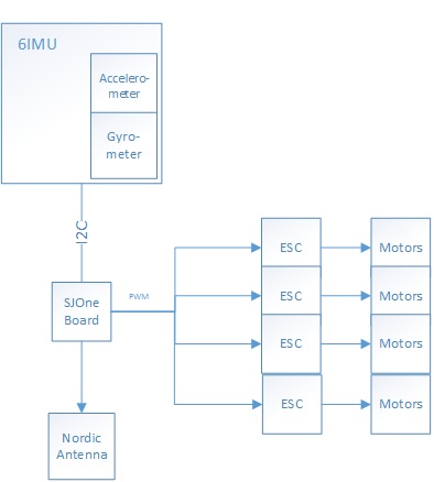
| + | Inertial measurement unit (IMU) - This module contains a built in Accelerometer and Gyrometer. Using these two sensors, the team is able to determine the quadcopter's orientation. | ||
| + | |||
| + | |||
| + | Nordic Antenna - This on-board module is used to receive the commands sent from the controller. | ||
| + | |||
| + | |||
| + | Electronic Speed Controls (ESC)- This device is used as a medium between the microcontroller and the brushless motors. The ESCs are initially calibrated with a range of PWM signals. After calibration, the ESC's are able to translate the signals to the motor. Additionally, the ESC supplies the necessary current for the motors. | ||
| + | |||
| + | [[File:Cmpe244 S14 Divine WINd Quadcopter Full View.jpg | 400px ]] | ||
| + | |||
| + | =====Quadcopter Power Module===== | ||
| + | |||
| + | [[File:CmpE244_S14_Divine_WINd_Power_Module.jpg | 400px ]] | ||
| + | |||
| + | In order for the quadcopter to be mobile, a Lipo battery is used. The lipo battery has a 12.1V output. As shown above, through a +5V voltage regulator, the lipo battery powers the SJOne board. Also, the 12.1V is used to power the ESCs and the motors. It is important that a lipo battery is used, because the brushless motors drains at least 20A. | ||
| + | |||
| + | [[File:Cmpe244 S14 Divine WINd Quadcopter Board.jpg | 400px ]] | ||
| + | === Hardware Interface === | ||
| − | |||
| − | + | ====ESC Interface==== | |
The SJOne board communicates with the ESCs via PWM. The SJOne's PWM output is connected to the white wire of the ESCs 3 pin input. The ground is connected to the black wire, and the ESCs red wire is left hanging, because it is a 5V output. | The SJOne board communicates with the ESCs via PWM. The SJOne's PWM output is connected to the white wire of the ESCs 3 pin input. The ground is connected to the black wire, and the ESCs red wire is left hanging, because it is a 5V output. | ||
| Line 138: | Line 237: | ||
7) The ESCs has now internally calibrated its throttle acceptance. The user can now send different duty cycle ratings in order to manipulate all motors. | 7) The ESCs has now internally calibrated its throttle acceptance. The user can now send different duty cycle ratings in order to manipulate all motors. | ||
| + | |||
| + | |||
| + | ====Inertial Measurement Unit (IMU) Interface==== | ||
| + | |||
| + | The acceleroeter and gyrometer are packaged in the Sunkee 10DOF 9-axis Attitude Indicator. For this project's application, only the accelerometer and gyrometer are necessary to retrieve the quadcopter's current orientation. Due to this IMU's package, all sensors are tied on the I2C bus and are accessible via I2C. | ||
| + | |||
| + | ====Wireless Interface==== | ||
| + | |||
| + | The team decided to use the on board Norton wireless chip found on the SJOne board. It was tested and determined that the Nordic wireless has enough reach for what the quadcopter requires. The wireless is used in conjunction with the FreeRTOS system, such that actions are event driven. If the quadcopter doesn't receive a message in a given amount of time a timer sets the quadcopter to hover automatically. This is to protect the quadcopter in the case of a loss of communication between the copter and the remote. | ||
| + | |||
| + | Our wireless packets transmit two pieces of data, speed and orientation/movement. The orientation tells the copter whether to move forward, ascend, descend and so forth. | ||
=== Software Design === | === Software Design === | ||
| + | |||
| + | ==== Controller Software Design ==== | ||
| + | |||
[[File:CmpE244 S14 Divine WINd Quadcopter Control Logic.jpg]] | [[File:CmpE244 S14 Divine WINd Quadcopter Control Logic.jpg]] | ||
| − | + | ||
| + | ==== Quadcopter Software Design ==== | ||
The MPU-9150 consists of a 3-axis accelerometer, 3axis Gyroscope and a 3 axis magnetometer. its a one chip IMU solution with onboard Motion processor for sensor fusion.Though it inherently supports on board Sensor Fusion, the IP is undisclosed. Therefore we used the library for arduino by Pansenti. (https://github.com/Pansenti) | The MPU-9150 consists of a 3-axis accelerometer, 3axis Gyroscope and a 3 axis magnetometer. its a one chip IMU solution with onboard Motion processor for sensor fusion.Though it inherently supports on board Sensor Fusion, the IP is undisclosed. Therefore we used the library for arduino by Pansenti. (https://github.com/Pansenti) | ||
| Line 151: | Line 265: | ||
For testing, we coded a GUI in python. The code parses the serial data from the arduino and displays the orientation of the IMU in real-time using Vpython.(video and code to be linked). | For testing, we coded a GUI in python. The code parses the serial data from the arduino and displays the orientation of the IMU in real-time using Vpython.(video and code to be linked). | ||
| − | === Implementation === | + | === Software Implementation === |
| − | [[File:CmpE244 S14 | + | |
| − | + | ==== Controller Software Implementation ==== | |
| + | The controller software makes use of the SJONE’s on-board accelerometer and Nordic Wireless capabilities. By interfacing one SJONE board with three external buttons, the controller is able to send commands to a second SJONE board that is mounted on the quadcopter. | ||
| + | |||
| + | The controller operates on a very simple program. It consistently sends new information to the quadcopter based on the controller-board’s orientation, by reading from the accelerometer or the buttons. The external buttons set part of the package that is sent wirelessly, they control the pwm value being sent from the controller. There are a total of three external buttons and their corresponding commands are: lower pwm, increase pwm, or kill-switch. Depending on its orientation, the controller will send one of the following commands to the quadcopter: | ||
| + | |||
| + | *'''Forward''' – sent when the controller is tipped forward, causes the quadcopter move in a forward fashion. | ||
| + | *'''Backward''' – sent when the controller is tipped backward, causes the quadcopter to reverse. | ||
| + | *'''Lean right''' – sent when the controller is tilted to the right, causes the quadcopter to pan to the right. | ||
| + | *'''Lean left''' – sent when the controller is tilted to the left, causes the quadcopter to pan to the left. | ||
| + | *'''Ascend''' – sent when the “increase pwm” button is pressed, makes the quadcopter ascend. | ||
| + | *'''Descend''' – sent by pressing the “decrease pwm” button, makes the quadcopter descend. | ||
| + | *'''Hover''' – the default state, causes the quadcopter to hover in place. | ||
| + | |||
| + | The controller forms a wireless packet containing a pwm value and a command, as listed above, unless the kill-switch is in effect. In the case of the kill-switch being activated, the controller sends a pwm value that shuts down the propellers. | ||
| + | |||
| + | ==== Quadcopter Software Implementation ==== | ||
| + | From the previous section, it is possible to see that the controller software sends two values: a pwm motor value which represents the maximum speed of the motors and an orientation value. Therefor the quadcopter software design must incorporate a command decode and wireless receive functionality as well as the balancing algorithm in order to interact with the controller successfully. Our quadcopter software implementation can be divided into two main parts at a high level: an Rx Task and Balancing Task. These tasks must somehow communicate and so we have chosen to implement a queue for communication between the tasks. A top level diagram of this system can be seen below: | ||
| + | |||
| + | [[File:CmpE244 S14 Divine WINd Quadcopter Top Level.jpg | 450px]] | ||
| + | |||
| + | As seen in our top level diagram, our on board quadcopter system is composed of two main tasks. However, it is important to note the priority in which these two tasks have been implemented. From a design standpoint it must be the top priority to run the balancing algorithm, or else the quadcopter will simply fall out of the sky. Therefore, the quadcopter balancing task must be given top priority when scheduling the tasks. However, some weight must be given to the Rx task because it is quite important as well. For instance, if a kill command comes in, the quadcopter needs to know quickly. Therefore, after every balancing run, the balancing task will go to sleep for a very short time and the OS will switch to running the Rx task in order to check for new commands. | ||
| + | |||
| + | Now that the top level view is understand a little better, it is possible to focus on the balancing algorithm directly. There are many algorithms to choose from when trying to balance a quadcopter. Due to time constraints and certain hardware problems we encountered, we chose to go with the simplest approach, which is the complementary filter combined with a low pass software filter. The complementary filter can be summarize by the following equation: | ||
| + | |||
| + | ''angle = (1 - accel_weight)*(angle + gyroData * dt) + (accel_weight * accelData)'' | ||
| + | |||
| + | where typically accel_weight is a small number, such as .05. This formula basically allows us to use the data from the gyroscope to accurately measure the angle in the short term, but use the accelerometer data for the long run. The reason for this is that at very high speeds, there is quite a bit of vibration from the motors on the quadcopter. This vibration causes quite a bit of noise in accelerometer data and makes it quite untrustworthy in the short term. For instance you might get data value like: 10 10 11 12 52 48 26 13 10 11. This random spike could really mess up your system if you relied solely on the accelerometer data. However, by using the complementary filter, it allows us to smooth the data out. A top level diagram of this system can be described as follows: | ||
| + | |||
| + | [[File:CmpE244 S14 DivineWINd Complementary Filter.jpg | 450px]] | ||
== Testing & Technical Challenges == | == Testing & Technical Challenges == | ||
| − | |||
| − | |||
| − | + | ===Testing=== | |
| + | |||
| + | ==== Balance Testing ==== | ||
| + | There are two types of balance testing the team used. One test was to tie ropes on each side of the blades, and test the balance of each axis individually. With this setup, the team is able to fine tune the balancing algorithm. | ||
| + | |||
| + | The other type of balance test was to tie the quadcopter to an elevated platform. The platform allows the copter to full degree of motion. This platform enables us to test the quadcopter's balance with all motors on | ||
| + | |||
| + | ==== Full Flight Testing ==== | ||
| + | After testing, a full flight test is conducted. However, because the balancing algorithm failed, the copter crashed and damaged the frame and destroyed the propellers. | ||
| + | |||
| + | ===Technical Challenges=== | ||
| + | |||
| + | ==== Shipping Time ==== | ||
| + | '''Problem''': The first quadcopter kit was shipping from China. This problem may result in a possible 2-4 weeks delay in working on the project. | ||
| + | |||
| + | '''Solution''': In order to place it safe, the team ordered the same kit from an American retailer on Amazon. Additionally, the initial kit from China was delivered 10 days after ordering. | ||
| + | |||
| + | '''Suggestion''': Make sure parts are ordered in America | ||
| + | |||
| + | ==== Shorting Lipo Battery==== | ||
| + | '''Problem''': The team terminated the battery wires so that powering the quadcopter system will be convenient. When terminating, the power and ground wires touched, causing the Lipo battery to short and break. Lipo batteries are very volatiles and needs to be handled with care. | ||
| + | |||
| + | '''Solution''': Team ordered a higher-grade Lipo battery in order to increase quadcopter's flight time | ||
| + | |||
| + | '''Suggestion''': Make sure that power and ground do not cross | ||
| + | |||
| + | ===Flimsy Quadcopter Supplies=== | ||
| + | '''Problem''': ESCs and motors are bound to break. Team ordered an extra ESC online, but of a different brand. This resulted in a stronger ESC, which causes an imbalance when flying the quadcopter and delay in progress. | ||
| + | |||
| + | '''Solution''': Used spare parts from second quadcopter | ||
| + | |||
| + | '''Suggestion''': Order 2 more ESCs and motors of the same brand | ||
| + | |||
| + | ====Vibration and Noise==== | ||
| + | '''Problem''': The accelerometer is very sensitive to movements. With all four blades spinning at the same time, a significant amount of noise is affecting the accelerometer's readings. | ||
| + | |||
| + | '''Solution''': Used a rubber sheet over the accelerometer to damper the vibration. | ||
| + | |||
| + | '''Suggestion''': Use any type of dampering object. The most popular ones are moon gel or rubber. | ||
| − | === | + | The solution we implemented can be seen below: |
| − | + | ||
| + | [[File:Cmpe244 S14 Divine WINd Quadcopter IMU.jpg | 400px]] | ||
| + | |||
| + | ===Wrong Algorithm Approach=== | ||
| + | '''Problem''': The team approached the Complementary Filtering Algorithm due to its simplicity and easy implementation. This approach is not suitable for self-balance on a quadcopter due to not being able to adjust balance efficiently. | ||
| + | |||
| + | '''Solution''': Tried to optimize and fine tune the weighting of the algorithm and the PWM acceleration | ||
| + | |||
| + | '''Suggestion''': Use PID algoritm or flight controller | ||
== Conclusion == | == Conclusion == | ||
| − | + | Overall, the team was not able to complete the project due to very limited time constraints and the initial approach. The team's approach to use complementary filtering was not suitable for larger sized quadcopters. The team encountered many hardware and technical difficulties, including faulty hardware, delayed shipping, and setbacks due to mistakes. If the parts were ordered a month earlier, more progress may have been made. Also, the team did not realize the importance of developing a accurate testing rig. Although we were able to successfully tune the quadcopter using a two point tie system, where we could test the pitch and roll separately, once we introduced all four motors, it was a completely different challenge. The variability of 2 axes of freedom was much greater than our expectations. It was not until we designed a free rotating stand that we were able to test both axes simultaneously without flying and crashing our quadcopter. The stand we designed can be seen below: | |
| + | |||
| + | [[File:Cmpe244 S14 Divine WINd Quadcopter Stand.jpg | 400px ]] | ||
| + | |||
| + | If we were to start from scratch, we would probably design a smaller quadcopter and with our current knowledge be able to buy better parts. We learned that it is important to do a lot of research when buying parts and starting a quadcopter. | ||
=== Project Video === | === Project Video === | ||
| Line 171: | Line 361: | ||
=== Project Source Code === | === Project Source Code === | ||
| − | + | * [https://sourceforge.net/projects/sjsu/files/CmpE244_SJSU_S2014/ Sourceforge source code link] | |
== References == | == References == | ||
=== Acknowledgement === | === Acknowledgement === | ||
| − | + | Much of the knowledge and environment was provided by Preet for Cmpe 244. | |
=== References Used === | === References Used === | ||
| − | |||
| + | http://www.pieter-jan.com/node/11 | ||
| + | |||
| + | http://www.st.com/st-web-ui/static/active/en/resource/technical/document/datasheet/CD00265057.pdf | ||
| + | |||
| + | http://www.analog.com/static/imported-files/data_sheets/ADXL345.pdf | ||
| − | + | http://www.adafruit.com/datasheets/HMC5883L_3-Axis_Digital_Compass_IC.pdf | |
| − | |||
| − | + | http://www.instructables.com/id/Guide-to-gyro-and-accelerometer-with-Arduino-inclu/ | |
| − | |||
Latest revision as of 23:40, 6 August 2014
Contents
Divine WINd
Abstract
Divine WINd is a quadcopter that focuses on stable flight and simple movement controls. There are two modules in which Divine WINd are composed of: the controller and the quadcopter. The controller module sends a signal to the quadcopter in how the quadcopter's pitch and roll orientation should be set to. The quadcopter's orientation dictates the type of movement the quadcopter will perform.
In order to set to the quadcopter to its desired orientation, an accelerometer and gyrometer are implemented in order to receive the quadcopter's current orientation. The quadcopter will then adjust the speed of its fan blades to balance itself in order to be re-positioned to its the desired orientation.
Objectives & Introduction
The project goal was to develop a control system for a quadcopter such that it can perform basic flight motions as received from a transmitting remote.
- Remote Control
- Comprised of an SJONE board and using the Nordic Wireless to send two data packets to the quadcopter.
- This remote must control the speed and the motions of the quadcopter.
- A kill-switch must be implemented such that the quadcopter remains in a hover or dead state until disabled.
- Quadcopter Controls
- Receives data from the remote controller corresponding to speed and orientation.
- Quadcopter must stabilize and perform operations received.
- Quadcopter must keep a timer such that if communication is broken, it defaults to hover mode.
- Kill switches, when enabled, must stay in effect until disabled and Quadcopter
Team Members & Primary Responsibilities
- Ryan Marlin
- Quadcopter Balance Implementation
- Eriberto Velazquez
- Wireless Control System Implementation
- Devin Villarosa
- Research and Hardware Implementation
How Quadcopters Fly
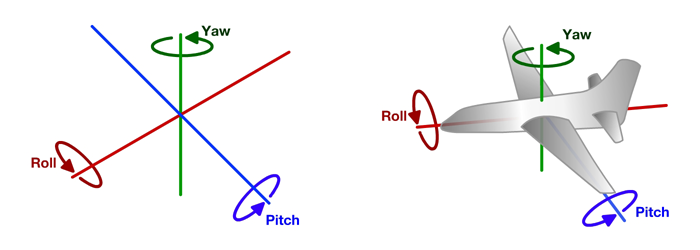
All flying machines has three axes of motion: Roll, Pitch, and Yaw. For this design, the quadcopter is only focused in Roll and Pitch. Roll and Pitch movements are enough for basic Quadcopter movements.
Balance is the main importance for flight. A quadcopter has four blades in which two blades spins clockwise and the other two spins counter clockwise. Each pair of blades adjusts its speed to balance out its axis. In order to perform simple movements, the quadcopter must be balanced at a particular orientation in order to move to the desired location.
Final Parts List
| Quantity | Items | Notes |
| 1 | Bumblebee 550 Quadcopter Kit | Kit came with 4x 20A High Speed ESC, 4x 2812 Brushless Motors 4, and 4x 10x3.8 Props. Manufacturer and part number are unidentifiable. http://www.amazon.com/Bumblebee-Quadcopter-10x3-8-Props-Motor/dp/B009P1UYBK/ref=sr_1_sc_1?s=toys-and-games&ie=UTF8&qid=1398390072&sr=1-1-spell&keywords=bumblebee+quadcopyter |
| 1 | Sunkee 10DOF 9-axis Attitude Indicator L3G4200D ADXL345 HMC5883L BMP085 Module Arduino | http://www.amazon.com/gp/product/B00CD239UG/ref=oh_details_o09_s02_i01?ie=UTF8&psc=1 |
| 1 | Bias 60C 4S 5000mAh 14.8V LiPO Battery with Uni Plug | http://www.amazon.com/gp/product/B00FMYY30W/ref=oh_details_o05_s00_i00?ie=UTF8&psc=1 |
| 2 | SJOne board | http://www.socialledge.com/sjsu/index.php?title=SJ_One_Board |
| 4 | JST Connectors | Used for convenience to connect Lipo batteries to ESCs |
| 1 | 5V voltage regulator | Used for quadcopter's power module |
| 2 | Wire terminals | Used for quadcopter's power module |
| 1 | Circular Protoboard | Used for quadcopter's power module |
| 1 | Header Pins | Used for quadcopter's power module |
| 1 | 4x4 Matrix Keypad | Used for quadcopter's control module |
Schedule
| Task | Projected Completion Date | Actual Completion Date | Status | Notes |
| Buy and Order Parts | 6-Mar | 13-Mar | Complete | Delayed due to researching how to build quadcopter. Ended up ordering a Quadcopter Kit for amateurs' convenience. Parts are ordered from Hong Kong. Customs may take 10+ days plus additional days for shipping (10-30 days). Ordered another kit from U.S. warehouse to complete project on time. |
| Build Quadcopter | 20-Mar | 26-Mar | Complete | The instructions are mixed in Chinese and English. Diagrams to construct quadcopter is doable, but not great |
| Install Quadcopter Sensors | 20-Mar | 18-Apr | Complete | Simple I2C interface. Powering and finding each sensor's address ID may not be as simple |
| Install Quadcopter Power Unit | 20-Mar | 5-Apr | Complete | Unavailablity of JST connectors and Shorting Lipo battery caused a minor setback |
| Implement Quadcopter Movement System | 27-Mar | Incomplete | Breaking an ESC, motor, and propellars caused setbacks. Using a replacement ESC that does not match the other ESC's causes more difficulty in implementation | |
| Implement Control System Inputs | 3-Apr | 3-Apr | Complete | |
| Implement Control System's Wireless Communication | 10-Apr | 12-Apr | Complete | Used on-board Nordic Antenna with given API |
| Implement Quadcopter IP Camera | 17-Apr | Unavailable | Unavailable | SJOne board does not have enough power to handle video imaging. Too late to redesign with high level microcontroller |
| Implement IP Camera Output on LCD Controller with wireless communication | 24-Apr | Unavailable | Unavailable | SJOne board does not have enough power to handle video imaging. Too late to redesign with high level microcontroller |
| Test for Demo / Final touches | 1-May | 22-May | Complete | |
| Demo | 8-May | 22-May | Semi-Complete |
Design & Implementation
Hardware Design
Controller Module
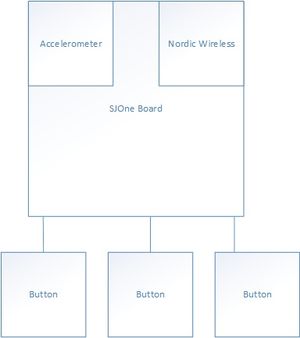
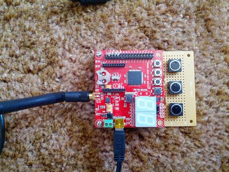
The controller module uses the SJOne's built in accelerometer and Nordic Wireless modules. The user turns the accelerometer in order to move the quadcopter (Forwards, Backwards, Left, Right). The 3 GPIO buttons are used to control the quadcopter's blade speeds. Button 1 is used to increase blade speed (increase altitude), button 2 is used to decrease speed (decrease altitude), and button 3 is used to kill all blades.
Quadcopter Module
The quadcopter is composed of several peripherals.
Inertial measurement unit (IMU) - This module contains a built in Accelerometer and Gyrometer. Using these two sensors, the team is able to determine the quadcopter's orientation.
Nordic Antenna - This on-board module is used to receive the commands sent from the controller.
Electronic Speed Controls (ESC)- This device is used as a medium between the microcontroller and the brushless motors. The ESCs are initially calibrated with a range of PWM signals. After calibration, the ESC's are able to translate the signals to the motor. Additionally, the ESC supplies the necessary current for the motors.
Quadcopter Power Module
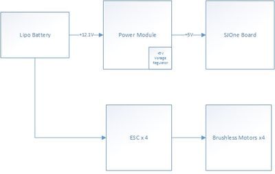
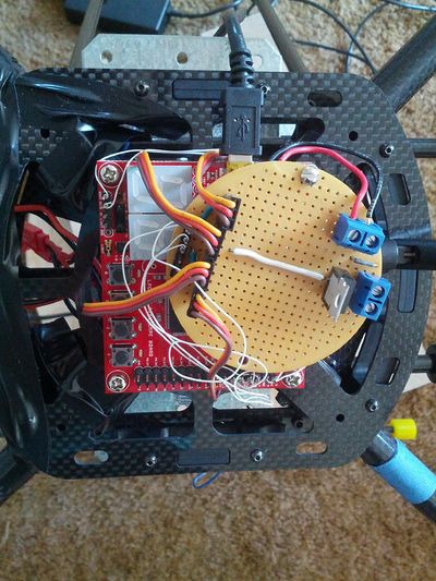
In order for the quadcopter to be mobile, a Lipo battery is used. The lipo battery has a 12.1V output. As shown above, through a +5V voltage regulator, the lipo battery powers the SJOne board. Also, the 12.1V is used to power the ESCs and the motors. It is important that a lipo battery is used, because the brushless motors drains at least 20A.
Hardware Interface
ESC Interface
The SJOne board communicates with the ESCs via PWM. The SJOne's PWM output is connected to the white wire of the ESCs 3 pin input. The ground is connected to the black wire, and the ESCs red wire is left hanging, because it is a 5V output. In order to calibrate the ESCs, so that the ESC can produce the range in which the PWM's duty cycle dictates the rate in which the motor produces, the following steps must take place, depending on the ESC manufacturer.
The following steps are used to calibrate this project's ESC:
1) Disconnect power to the ESC
2) Set PWM to an acceptable ESC frequency (between 100hz - 400hz)
3) Set PWM duty cycle to its maximum rating (99%) (This step simulates using a flight controller's transceiver's throttle to the maximum)
4) Plug power to the ESCs
5) Until ESCs gives "beeping signal" in which it accepted its maximum throttle rating, set PWM to lowest throttle (0%) (This simulates using a flight's controller to its minimum throttle).
6) Wait until ESCs "beeps" to signal that accepted minimum throttle is accepted
7) The ESCs has now internally calibrated its throttle acceptance. The user can now send different duty cycle ratings in order to manipulate all motors.
Inertial Measurement Unit (IMU) Interface
The acceleroeter and gyrometer are packaged in the Sunkee 10DOF 9-axis Attitude Indicator. For this project's application, only the accelerometer and gyrometer are necessary to retrieve the quadcopter's current orientation. Due to this IMU's package, all sensors are tied on the I2C bus and are accessible via I2C.
Wireless Interface
The team decided to use the on board Norton wireless chip found on the SJOne board. It was tested and determined that the Nordic wireless has enough reach for what the quadcopter requires. The wireless is used in conjunction with the FreeRTOS system, such that actions are event driven. If the quadcopter doesn't receive a message in a given amount of time a timer sets the quadcopter to hover automatically. This is to protect the quadcopter in the case of a loss of communication between the copter and the remote.
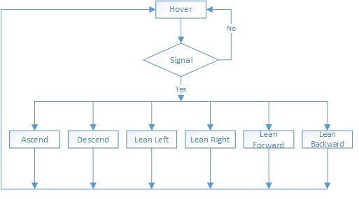
Our wireless packets transmit two pieces of data, speed and orientation/movement. The orientation tells the copter whether to move forward, ascend, descend and so forth.
Software Design
Controller Software Design
Quadcopter Software Design
The MPU-9150 consists of a 3-axis accelerometer, 3axis Gyroscope and a 3 axis magnetometer. its a one chip IMU solution with onboard Motion processor for sensor fusion.Though it inherently supports on board Sensor Fusion, the IP is undisclosed. Therefore we used the library for arduino by Pansenti. (https://github.com/Pansenti) The 6 axis sensor fusion (accel+gyro) is done on the MPU and sent to an arduino where the magnetometer data is used for YAW correction. The arduino transmits the orientation data over UART which is recieved by the SJONE for further processing.
For testing, we coded a GUI in python. The code parses the serial data from the arduino and displays the orientation of the IMU in real-time using Vpython.(video and code to be linked).
Software Implementation
Controller Software Implementation
The controller software makes use of the SJONE’s on-board accelerometer and Nordic Wireless capabilities. By interfacing one SJONE board with three external buttons, the controller is able to send commands to a second SJONE board that is mounted on the quadcopter.
The controller operates on a very simple program. It consistently sends new information to the quadcopter based on the controller-board’s orientation, by reading from the accelerometer or the buttons. The external buttons set part of the package that is sent wirelessly, they control the pwm value being sent from the controller. There are a total of three external buttons and their corresponding commands are: lower pwm, increase pwm, or kill-switch. Depending on its orientation, the controller will send one of the following commands to the quadcopter:
- Forward – sent when the controller is tipped forward, causes the quadcopter move in a forward fashion.
- Backward – sent when the controller is tipped backward, causes the quadcopter to reverse.
- Lean right – sent when the controller is tilted to the right, causes the quadcopter to pan to the right.
- Lean left – sent when the controller is tilted to the left, causes the quadcopter to pan to the left.
- Ascend – sent when the “increase pwm” button is pressed, makes the quadcopter ascend.
- Descend – sent by pressing the “decrease pwm” button, makes the quadcopter descend.
- Hover – the default state, causes the quadcopter to hover in place.
The controller forms a wireless packet containing a pwm value and a command, as listed above, unless the kill-switch is in effect. In the case of the kill-switch being activated, the controller sends a pwm value that shuts down the propellers.
Quadcopter Software Implementation
From the previous section, it is possible to see that the controller software sends two values: a pwm motor value which represents the maximum speed of the motors and an orientation value. Therefor the quadcopter software design must incorporate a command decode and wireless receive functionality as well as the balancing algorithm in order to interact with the controller successfully. Our quadcopter software implementation can be divided into two main parts at a high level: an Rx Task and Balancing Task. These tasks must somehow communicate and so we have chosen to implement a queue for communication between the tasks. A top level diagram of this system can be seen below:
As seen in our top level diagram, our on board quadcopter system is composed of two main tasks. However, it is important to note the priority in which these two tasks have been implemented. From a design standpoint it must be the top priority to run the balancing algorithm, or else the quadcopter will simply fall out of the sky. Therefore, the quadcopter balancing task must be given top priority when scheduling the tasks. However, some weight must be given to the Rx task because it is quite important as well. For instance, if a kill command comes in, the quadcopter needs to know quickly. Therefore, after every balancing run, the balancing task will go to sleep for a very short time and the OS will switch to running the Rx task in order to check for new commands.
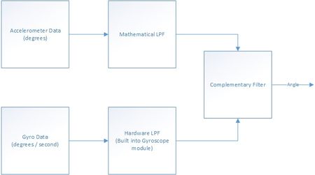
Now that the top level view is understand a little better, it is possible to focus on the balancing algorithm directly. There are many algorithms to choose from when trying to balance a quadcopter. Due to time constraints and certain hardware problems we encountered, we chose to go with the simplest approach, which is the complementary filter combined with a low pass software filter. The complementary filter can be summarize by the following equation:
angle = (1 - accel_weight)*(angle + gyroData * dt) + (accel_weight * accelData)
where typically accel_weight is a small number, such as .05. This formula basically allows us to use the data from the gyroscope to accurately measure the angle in the short term, but use the accelerometer data for the long run. The reason for this is that at very high speeds, there is quite a bit of vibration from the motors on the quadcopter. This vibration causes quite a bit of noise in accelerometer data and makes it quite untrustworthy in the short term. For instance you might get data value like: 10 10 11 12 52 48 26 13 10 11. This random spike could really mess up your system if you relied solely on the accelerometer data. However, by using the complementary filter, it allows us to smooth the data out. A top level diagram of this system can be described as follows:
Testing & Technical Challenges
Testing
Balance Testing
There are two types of balance testing the team used. One test was to tie ropes on each side of the blades, and test the balance of each axis individually. With this setup, the team is able to fine tune the balancing algorithm.
The other type of balance test was to tie the quadcopter to an elevated platform. The platform allows the copter to full degree of motion. This platform enables us to test the quadcopter's balance with all motors on
Full Flight Testing
After testing, a full flight test is conducted. However, because the balancing algorithm failed, the copter crashed and damaged the frame and destroyed the propellers.
Technical Challenges
Shipping Time
Problem: The first quadcopter kit was shipping from China. This problem may result in a possible 2-4 weeks delay in working on the project.
Solution: In order to place it safe, the team ordered the same kit from an American retailer on Amazon. Additionally, the initial kit from China was delivered 10 days after ordering.
Suggestion: Make sure parts are ordered in America
Shorting Lipo Battery
Problem: The team terminated the battery wires so that powering the quadcopter system will be convenient. When terminating, the power and ground wires touched, causing the Lipo battery to short and break. Lipo batteries are very volatiles and needs to be handled with care.
Solution: Team ordered a higher-grade Lipo battery in order to increase quadcopter's flight time
Suggestion: Make sure that power and ground do not cross
Flimsy Quadcopter Supplies
Problem: ESCs and motors are bound to break. Team ordered an extra ESC online, but of a different brand. This resulted in a stronger ESC, which causes an imbalance when flying the quadcopter and delay in progress.
Solution: Used spare parts from second quadcopter
Suggestion: Order 2 more ESCs and motors of the same brand
Vibration and Noise
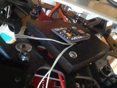
Problem: The accelerometer is very sensitive to movements. With all four blades spinning at the same time, a significant amount of noise is affecting the accelerometer's readings.
Solution: Used a rubber sheet over the accelerometer to damper the vibration.
Suggestion: Use any type of dampering object. The most popular ones are moon gel or rubber.
The solution we implemented can be seen below:
Wrong Algorithm Approach
Problem: The team approached the Complementary Filtering Algorithm due to its simplicity and easy implementation. This approach is not suitable for self-balance on a quadcopter due to not being able to adjust balance efficiently.
Solution: Tried to optimize and fine tune the weighting of the algorithm and the PWM acceleration
Suggestion: Use PID algoritm or flight controller
Conclusion
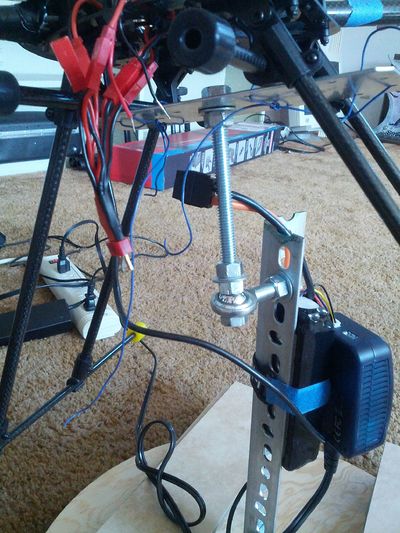
Overall, the team was not able to complete the project due to very limited time constraints and the initial approach. The team's approach to use complementary filtering was not suitable for larger sized quadcopters. The team encountered many hardware and technical difficulties, including faulty hardware, delayed shipping, and setbacks due to mistakes. If the parts were ordered a month earlier, more progress may have been made. Also, the team did not realize the importance of developing a accurate testing rig. Although we were able to successfully tune the quadcopter using a two point tie system, where we could test the pitch and roll separately, once we introduced all four motors, it was a completely different challenge. The variability of 2 axes of freedom was much greater than our expectations. It was not until we designed a free rotating stand that we were able to test both axes simultaneously without flying and crashing our quadcopter. The stand we designed can be seen below:
If we were to start from scratch, we would probably design a smaller quadcopter and with our current knowledge be able to buy better parts. We learned that it is important to do a lot of research when buying parts and starting a quadcopter.
Project Video
Upload a video of your project and post the link here.
Project Source Code
References
Acknowledgement
Much of the knowledge and environment was provided by Preet for Cmpe 244.
References Used
http://www.pieter-jan.com/node/11
http://www.st.com/st-web-ui/static/active/en/resource/technical/document/datasheet/CD00265057.pdf
http://www.analog.com/static/imported-files/data_sheets/ADXL345.pdf
http://www.adafruit.com/datasheets/HMC5883L_3-Axis_Digital_Compass_IC.pdf
http://www.instructables.com/id/Guide-to-gyro-and-accelerometer-with-Arduino-inclu/
