Difference between revisions of "S20: Bucephalus"
Proj user2 (talk | contribs) (→Hardware Integration:- Printed Circuit Board) |
Proj user2 (talk | contribs) (→Technical Challenges) |
||
| (412 intermediate revisions by 4 users not shown) | |||
| Line 1: | Line 1: | ||
| − | [[File:Final.jpg|thumb|1000px|caption|right|Bucephalus Logo]] | + | [[File:Final.jpg|thumb|1000px|caption|right|Bucephalus Logo]] |
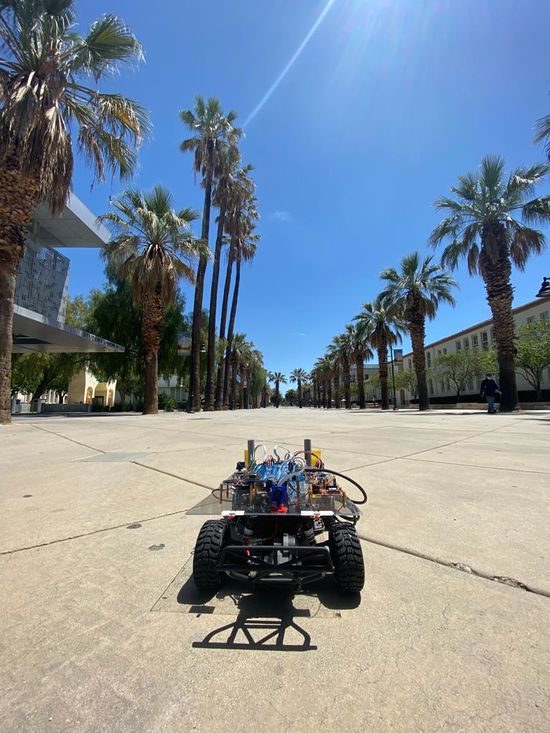
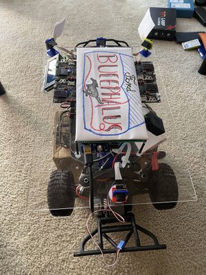
| + | [[File:car_2.jpg|thumb|550px|caption|right|Bucephalus car picture]] | ||
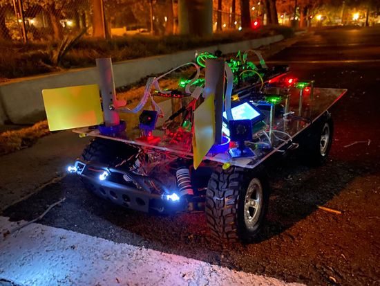
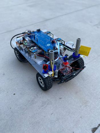
| + | == Bucephalus Picture == | ||
| + | {| style="margin-left: auto; margin-right: auto; border: none;" | ||
| + | |[[File:car_1.jpg|right|550px|thumb|Bucephalus car Night view with headlights]] | ||
| + | | | ||
| + | |[[File:car_3.jpg|right|350px|thumb|Bucephalus car Day view]] | ||
| + | | | ||
| + | |} | ||
| + | |||
| + | == Abstract == | ||
| − | + | Bucephalus is a Self Driving RC car using CAN communication based on FreeRTOS. The RC car takes real time inputs and covert it into the data that can be processed to monitor and control to meet the desired requirements. In this project, we aim to design and develop a self-driving car that autonomously navigates from the current location to the destination (using <B> Waypoint Algorithm </B>)which is selected through an Android application and at the same time avoiding all the obstacles in the path using <B> Obstacle avoidance algorithm </B>. It also Increases or Decreases speed on Uphill and downhill (using <B> PID Algorithm</B>)as well as applies breaks at required places. The car comprises of 4 control units communicating with each other over the CAN Bus using CAN communication protocol, each having a specific functionality that helps the car to navigate to its destination successfully.<BR/> | |
| − | Bucephalus is a Self Driving RC car using CAN communication based on FreeRTOS | ||
<BR/> | <BR/> | ||
| − | === | + | === Introduction === |
| − | '''Objectives of the RC Car: | + | '''Objectives of the RC Car:''' |
| − | 1) <B>Driver Controller: | + | 1) <B>Driver Controller:</B> Detection and avoidance of the obstacles coming in the path of the RC car by following Obstacle detection avoidance.<br /> |
| − | 2) <B>Geographical Controller: | + | 2) <B>Geographical Controller:</B> Getting the GPS coordinates from the Android Application and traveling to that point using Waypoint Algorithm<br /> |
3) System hardware communication using PCB Design. <BR/> | 3) System hardware communication using PCB Design. <BR/> | ||
| − | 4) <B>Bridge and Sensor Controller: | + | 4) <B>Bridge and Sensor Controller:</B> Communication between the Driver Board and Android Mobile Application using wireless bluetooth commmunication.<BR/> |
| − | 5) <B>Motor Controller: | + | 5) <B>Motor Controller:</B> Control the Servo Motor for Direction and DC motor for speed. Implementation of PID Algorithm on normal road uphill and down hill to maintain speed<br/><BR/> |
'''The project is divided into six main modules:''' | '''The project is divided into six main modules:''' | ||
| − | |||
{| class="wikitable" style="margin-left: 0px; margin-right: auto;" | {| class="wikitable" style="margin-left: 0px; margin-right: auto;" | ||
|- style="vertical-align: top;" | |- style="vertical-align: top;" | ||
| Line 24: | Line 32: | ||
* <span style="color:#FFA500">Android Mobile Application</span> | * <span style="color:#FFA500">Android Mobile Application</span> | ||
* <span style="color:#CDCC1C">Bridge and Sensor Controller</span> | * <span style="color:#CDCC1C">Bridge and Sensor Controller</span> | ||
| − | * <span style="color:#33BAFF"> | + | * <span style="color:#33BAFF">Geographical Controller</span> |
* <span style="color:#FF00FF">Driver and LCD Controller</span> <br /> | * <span style="color:#FF00FF">Driver and LCD Controller</span> <br /> | ||
* <span style="color:#4CA821">Motor Controller</span> <br /> | * <span style="color:#4CA821">Motor Controller</span> <br /> | ||
| Line 30: | Line 38: | ||
|} | |} | ||
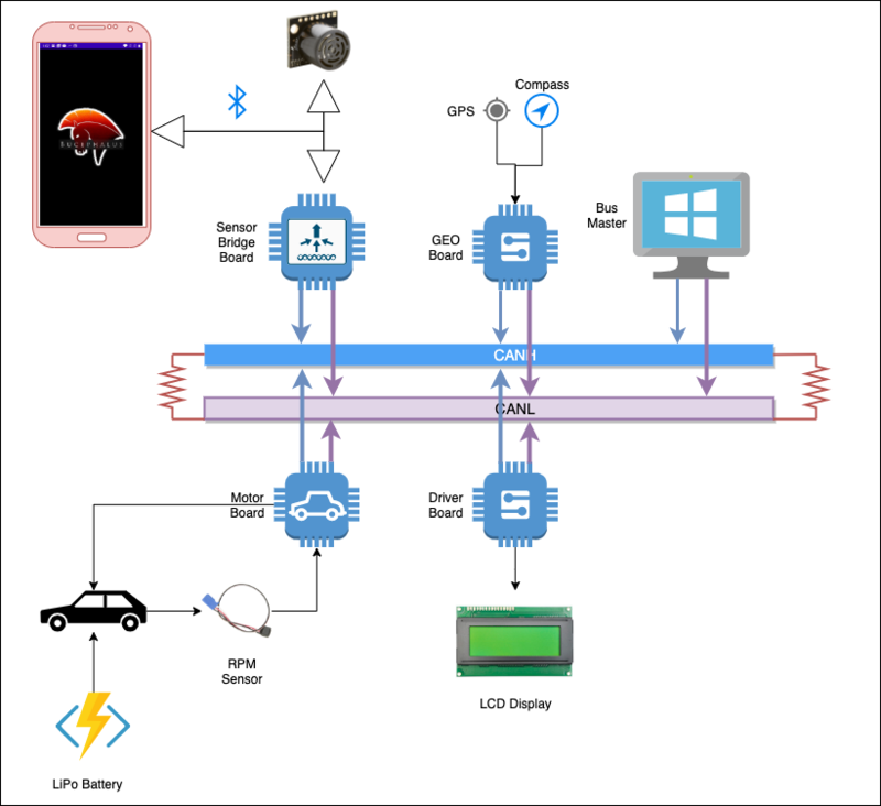
| − | + | '''Project overview:''' | |
| − | + | [[File:Cmpe243_s20_project_architecture.png|thumb|center|800px| Project Overview]] | |
| + | |||
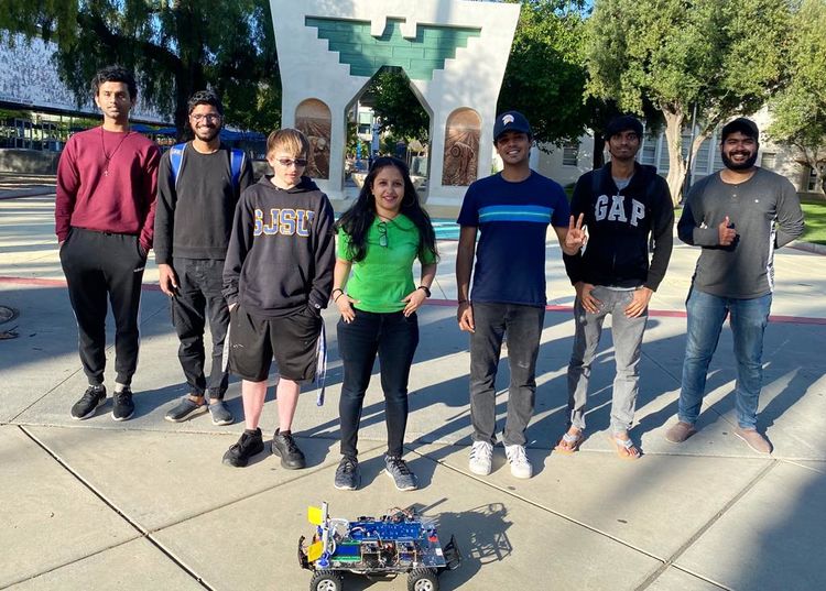
| + | == Team Members & Responsibilities == | ||
| + | |||
| + | [[File:Team_picture_b.jpg|thumb|750px|caption|right|Team Picture]] | ||
'''Bucephalous GitLab - [https://gitlab.com/bucephalus/sjtwo-c/-/tree/master]''' | '''Bucephalous GitLab - [https://gitlab.com/bucephalus/sjtwo-c/-/tree/master]''' | ||
| Line 37: | Line 49: | ||
* <font color="black"> '''Mohit Ingale [https://gitlab.com/mohitingale GitLab] [https://www.linkedin.com/in/mohitingale/ LinkedIn]''' | * <font color="black"> '''Mohit Ingale [https://gitlab.com/mohitingale GitLab] [https://www.linkedin.com/in/mohitingale/ LinkedIn]''' | ||
** <font color="FUCHSIA"> '''Driver and LCD Controller''' | ** <font color="FUCHSIA"> '''Driver and LCD Controller''' | ||
| − | ** <font color="red"> '''Hardware Integration | + | ** <font color="red"> '''Hardware Integration and PCB Designing''' |
** <font color="blue"> '''Testing Team / Code Reviewers''' | ** <font color="blue"> '''Testing Team / Code Reviewers''' | ||
* <font color="black"> '''Shreya Patankar [https://gitlab.com/shreya_patankar GitLab] [https://www.linkedin.com/in/shreya-patankar/ LinkedIn]''' | * <font color="black"> '''Shreya Patankar [https://gitlab.com/shreya_patankar GitLab] [https://www.linkedin.com/in/shreya-patankar/ LinkedIn]''' | ||
** <font color="33BAFF"> '''Geographical Controller''' | ** <font color="33BAFF"> '''Geographical Controller''' | ||
| − | ** <font color="red"> '''Hardware Integration | + | ** <font color="red"> '''Hardware Integration and PCB Designing''' |
** <font color="blue"> '''Testing Team / Code Reviewers''' | ** <font color="blue"> '''Testing Team / Code Reviewers''' | ||
** <font color="B933FF"> '''Wiki Page''' | ** <font color="B933FF"> '''Wiki Page''' | ||
| Line 49: | Line 61: | ||
** <font color="CDCC1C">'''Bridge and Sensor Controller''' | ** <font color="CDCC1C">'''Bridge and Sensor Controller''' | ||
** <font color="B933FF"> '''Wiki Page''' | ** <font color="B933FF"> '''Wiki Page''' | ||
| − | ** <font color="red"> '''Hardware Integration | + | ** <font color="red"> '''Hardware Integration and PCB Designing''' |
* <font color="black">'''Joel Samson [https://gitlab.com/joel_samson GitLab] [https://www.linkedin.com/in/joel-samson-86240b105/ LinkedIn]''' | * <font color="black">'''Joel Samson [https://gitlab.com/joel_samson GitLab] [https://www.linkedin.com/in/joel-samson-86240b105/ LinkedIn]''' | ||
| Line 57: | Line 69: | ||
** <font color="4CA821"> '''Motor Controller''' | ** <font color="4CA821"> '''Motor Controller''' | ||
** <font color="blue"> '''Testing Team / Code Reviewers''' | ** <font color="blue"> '''Testing Team / Code Reviewers''' | ||
| − | ** <font color="red"> '''Hardware Integration | + | ** <font color="red"> '''Hardware Integration and PCB Designing''' |
* <font color="black"> '''Basangouda Patil [https://gitlab.com/basangouda46 GitLab] [https://www.linkedin.com/in/basangoudapatil/ LinkedIn]''' | * <font color="black"> '''Basangouda Patil [https://gitlab.com/basangouda46 GitLab] [https://www.linkedin.com/in/basangoudapatil/ LinkedIn]''' | ||
| Line 66: | Line 78: | ||
** <font color="FUCHSIA"> '''Driver and LCD Controller''' | ** <font color="FUCHSIA"> '''Driver and LCD Controller''' | ||
** <font color="blue"> '''Testing Team / Code Reviewers''' | ** <font color="blue"> '''Testing Team / Code Reviewers''' | ||
| − | ** <font color="red"> '''Hardware Integration | + | ** <font color="red"> '''Hardware Integration and PCB Designing'''<font color="black"> |
<BR/> | <BR/> | ||
| Line 84: | Line 96: | ||
| 02/22/2020 | | 02/22/2020 | ||
| | | | ||
| − | * Setup a team Google Docs folder | + | * <font color="black">Setup a team Google Docs folder |
| − | * Brainstorm RC car design options | + | * <font color="black">Brainstorm RC car design options |
| − | * Research past semester RC car projects for ideas and parts needed | + | * <font color="black">Research past semester RC car projects for ideas and parts needed |
| − | * Put together a rough draft parts list | + | * <font color="black">Put together a rough draft parts list |
| − | * Setup a team GitLab repository | + | * <font color="black">Setup a team GitLab repository |
| | | | ||
| Line 101: | Line 113: | ||
| 02/29/2020 | | 02/29/2020 | ||
| | | | ||
| − | * Decide on and order chassis | + | * <font color="black">Decide on and order chassis |
| − | * Discuss possible GPS modules | + | * <font color="black">Discuss possible GPS modules |
| − | * Discuss schedule for meeting dates and work days (Tuesdays are for code review and syncing, Saturdays are work days) | + | * <font color="black">Discuss schedule for meeting dates and work days (Tuesdays are for code review and syncing, Saturdays are work days) |
| − | * Discuss bluetooth communication approach (1 phone on car, 1 phone in controller's hands) | + | * <font color="black">Discuss bluetooth communication approach (1 phone on car, 1 phone in controller's hands) |
| − | * Discuss vehicle's driving checkpoints (checkpoints calculated after point B is specified) | + | * <font color="black">Discuss vehicle's driving checkpoints (checkpoints calculated after point B is specified) |
| − | * Discuss wiring on RC car (1 battery to power motors and 1 power bank for everything else) | + | * <font color="black">Discuss wiring on RC car (1 battery to power motors and 1 power bank for everything else) |
| − | * Discuss GitLab workflow (mirror our repo with Preet's, 3 approvals to merge to "working master" branch, resolve conflicts on "working master" branch, then can merge to master branch) | + | * <font color="black">Discuss GitLab workflow (mirror our repo with Preet's, 3 approvals to merge to "working master" branch, resolve conflicts on "working master" branch, then can merge to master branch) |
| | | | ||
| Line 123: | Line 135: | ||
| 03/07/2020 | | 03/07/2020 | ||
| | | | ||
| − | * Decide on sensors (4 ultrasonic sensors: 3 in front, 1 in back) | + | * <font color="black">Decide on sensors (4 ultrasonic sensors: 3 in front, 1 in back) |
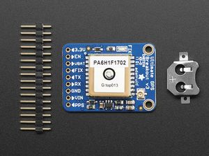
| − | * Decide on a GPS module (Adafruit ADA746) | + | * <font color="black">Decide on a GPS module (Adafruit ADA746) |
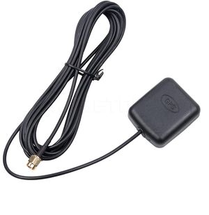
| − | * Research GPS antennas | + | * <font color="black">Research GPS antennas |
| − | * Decide on CAN transceivers (SN65HVD230 IC's) | + | * <font color="black">Decide on CAN transceivers (SN65HVD230 IC's) |
| − | * Request 15 CAN transceiver samples from ti.com | + | * <font color="black">Request 15 CAN transceiver samples from ti.com |
| − | * Discuss tasks of all 4 board nodes (geographical, driver, motors, bridge controller/sensors) | + | * <font color="black">Discuss tasks of all 4 board nodes (geographical, driver, motors, bridge controller/sensors) |
| | | | ||
* Completed | * Completed | ||
| Line 142: | Line 154: | ||
| 03/14/2020 | | 03/14/2020 | ||
| | | | ||
| − | * Assemble car chassis and plan general layout | + | * <font color="black">Assemble car chassis and plan general layout |
| − | * Delegate tasks for each 2 person teams | + | * <font color="black">Delegate tasks for each 2 person teams |
| − | * Create branches for all nodes and add motor and sensor messages to DBC file | + | * <font color="black">Create branches for all nodes and add motor and sensor messages to DBC file |
| − | * Discuss and research possible GPS antennas | + | * <font color="black">Discuss and research possible GPS antennas |
| − | * Design block diagrams for motor node, bridge controller/sensor node, and full car | + | * <font color="black">Design block diagrams for motor node, bridge controller/sensor node, and full car |
| − | * Solve GitLab branches vs folders issue (1 branch per node, or 1 folder per node) | + | * <font color="black">Solve GitLab branches vs folders issue (1 branch per node, or 1 folder per node) |
| − | * Order 4 + 1 extra ultrasonic sensors (MaxBotix MB1003-000 HRLV-MaxSonar-EZ0) | + | * <font color="black">Order 4 + 1 extra ultrasonic sensors (MaxBotix MB1003-000 HRLV-MaxSonar-EZ0) |
| | | | ||
| Line 164: | Line 176: | ||
| 03/21/2020 | | 03/21/2020 | ||
| | | | ||
| − | * Decide what to include on PCB board | + | * <font color="black">Decide what to include on PCB board |
| − | * | + | * <font color="black">Read previous student's reports to decide on a compass module (CMPS12) |
| − | + | * <font color="black">Order GPS antenna | |
| − | * | + | * <font color="black">Add GPS node messages (longitude, latitude, heading) and bridge sensor node messages (destination latitude and longitude) to DBC file |
| − | + | * <font color="orange">Start learning Android app development | |
| − | * < | + | * <font color="CDCC1C">Begin researching filtering algorithms for ultrasonic sensors |
| − | * Ultrasonic sensor values are converted to centimeters and transmit to driver node | + | * <font color="CDCC1C">Ultrasonic sensor values are converted to centimeters and transmit to driver node |
| − | * Research ultrasonic sensor mounts | + | * <font color="CDCC1C">Research ultrasonic sensor mounts |
| − | * Transmit CAN messages from sensor to driver node, and from driver to motor node | + | * <font color="CDCC1C">Transmit CAN messages from sensor to driver node, <font color="fuchsia">and from driver to motor node |
| − | * Decide movement and steering directions based on all possible sensor obstacle detection scenarios | + | * <font color="fuchsia">Driver node is able to respond correctly based on sensor obstacle detection scenarios (correct LED's light up) |
| − | * Begin research on PID implementation to control speed of RC car | + | * <font color="fuchsia">Decide movement and steering directions based on all possible sensor obstacle detection scenarios |
| − | + | * <font color="4CA821">Begin research on PID implementation to control speed of RC car | |
| | | | ||
| Line 196: | Line 208: | ||
| 03/28/2020 | | 03/28/2020 | ||
| | | | ||
| − | * Draw block diagrams with pin information for each board and begin PCB design based on these diagrams | + | * <font color="black">Draw block diagrams with pin information for each board and begin PCB design based on these diagrams |
| − | * Start implementing a basic Android app without Google maps API and create a separate GitLab repo for app | + | * <font color="black">Finalize parts list and place orders for remaining unordered items |
| − | * | + | * <font color="black">Decide on tap plastic acrylic sheet dimensions and PCB dimensions |
| − | + | * <font color="orange">Start implementing a basic Android app without Google maps API and create a separate GitLab repo for app | |
| − | * Decide on ultrasonic sensor mounts and order extra if needed | + | * <font color="CDCC1C">Bridge sensor node is able to transmit a destination latitude and longitude coordinates message to geological node |
| − | * | + | * <font color="CDCC1C">Decide on ultrasonic sensor mounts and order extra if needed |
| − | + | * <font color="33BAFF">Geological node is able to transmit a heading message to the driver node | |
| − | + | * <font color="fuchsia">Integrate driver board diagnostic testing with LEDs <font color="CDCC1C">and ultrasonic sensors (car goes left, left LEDs light up, etc.) | |
| − | + | * <font color="4CA821">Continue research on PID controller design and begin basic implementation | |
| − | + | * <font color="B933FF">Finish designing team logo and upload to Wiki page | |
| − | * Integrate driver board diagnostic testing with LEDs and ultrasonic sensors (car goes left, left LEDs light up, etc.) | ||
| | | | ||
| − | |||
* Completed | * Completed | ||
* Completed | * Completed | ||
| Line 226: | Line 236: | ||
| 04/04/2020 | | 04/04/2020 | ||
| | | | ||
| − | * Finish a basic implementation of filtering ultrasonic sensor's ADC data | + | * <font color="black">Complete rough draft of DBC file messages and signals |
| − | * | + | * <font color="black">Purchase tap plastic acrylic sheet |
| − | + | * <font color="orange">Learn how to integrate Google maps API into Android app | |
| − | + | * <font color="CDCC1C">Finish a basic implementation of filtering ultrasonic sensor's ADC data | |
| − | * Bluetooth Module driver is finished, can connect to Android phone, and can receive "Hello World" data from phone | + | * <font color="CDCC1C">Design a block diagram for optimal ultrasonic sensor placement |
| − | * | + | * <font color="CDCC1C">Bluetooth Module driver is finished, can connect to Android phone, and can receive "Hello World" data from phone |
| − | + | * <font color="33BAFF">Geological node is able to parse the GPS NMEA string to extract latitude and longitude coordinates | |
| − | + | * <font color="33BAFF">Geological node is able to receive a current heading (0-360 degrees) from the compass module | |
| − | * | + | * <font color="33BAFF">Geological node is able to receive an NMEA string from the GPS |
| − | + | * <font color="33BAFF">Geological node is able to compute the destination heading (0-360 degrees) and send to driver node | |
| − | * Geological node is able to receive an NMEA string from the GPS | + | * <font color="4CA821">Add PWM functionality to motor board code and test on DC and servo motors |
| − | * | + | * <font color="4CA821">Complete a basic implementation of encoder code on motor board |
| − | * | + | * <font color="B933FF">Complete rough draft of schedule and upload to Wiki page |
| | | | ||
| Line 260: | Line 270: | ||
| 04/11/2020 | | 04/11/2020 | ||
| | | | ||
| − | * Finish ultrasonic filtering algorithm for ultrasonic sensor's ADC data | + | * <font color="orange">Google maps API is fully integrated into Android App |
| − | * | + | * <font color="CDCC1C">Finish ultrasonic filtering algorithm for ultrasonic sensor's ADC data |
| − | * Bluetooth Module is able to receive data from Android app | + | * <font color="CDCC1C">Design ultrasonic sensor shields to minimize sensor interference with each other |
| − | * Test obstacle avoidance algorithm (indoor) | + | * <font color="CDCC1C">Bluetooth Module is able to receive data from Android app |
| − | * | + | * <font color="fuchsia">Test obstacle avoidance algorithm (indoor) |
| − | + | * <font color="4CA821">Complete motor board code controlling RC car's DC motor and servo motor | |
| − | * Begin car chassis wiring on a breadboard | + | * <font color="4CA821">Complete "push button" motor test (servo turns wheels left and right, and DC motor spins wheel forwards and backwards) |
| − | * Finalize and review PCB schematic | + | * <font color="red">Begin car chassis wiring on a breadboard |
| − | * Complete a rough draft car chassis block diagram for the placement of all boards and modules | + | * <font color="red">Finalize and review PCB schematic |
| − | + | * <font color="red">Complete a rough draft car chassis block diagram for the placement of all boards and modules | |
| | | | ||
| Line 288: | Line 298: | ||
| 04/18/2020 | | 04/18/2020 | ||
| | | | ||
| − | * Test obstacle avoidance algorithm ( | + | * <font color="black">Discuss checkpoint algorithm |
| − | * Complete car chassis wiring on a breadboard | + | * <font color="orange">Display sensor and motor data on Android app |
| − | * Establish and test CAN communication between all boards | + | * <font color="CDCC1C">Bluetooth module is able to receive "dummy" destination latitude and longitude coordinates from Android app |
| − | * | + | * <font color="33BAFF">Finish GPS module integration with geographical controller |
| − | + | * <font color="fuchsia">Test obstacle avoidance algorithm (outdoor) | |
| − | + | * <font color="4CA821">Test existing motor board code on RC car's motors | |
| − | * | + | * <font color="4CA821">Begin wheel encoder implementation and unit testing |
| − | + | * <font color="red">Complete car chassis wiring on a breadboard | |
| − | * | + | * <font color="red">Establish and test CAN communication between all boards |
| − | + | * <font color="red">Design and solder a prototype PCB board in case PCB isn't delivered in time | |
| − | + | * <font color="red">Mount sensors, motors, LCD, and all four sjtwo boards onto car chassis | |
| − | + | * <font color="red">Finish routing PCB and review to verify the circuitry | |
| | | | ||
| Line 320: | Line 330: | ||
| 04/25/2020 | | 04/25/2020 | ||
| | | | ||
| − | * | + | * <font color="orange">Android app is able to send start and stop commands to the car |
| − | * Test drive outdoors to check obstacle avoidance algorithm | + | * <font color="orange">Android app is able to display car data (speed, sensor values, destination coordinates, source coordinates) |
| − | * | + | * <font color="CDCC1C">Bluetooth module is able to receive actual destination latitude and longitude coordinates from Android app |
| − | * Begin unit testing the PID control algorithm | + | * <font color="fuchsia">Test drive outdoors to check obstacle avoidance algorithm |
| − | * | + | * <font color="4CA821">Complete motor control code with optimal speed and PWM values without PID control |
| − | + | * <font color="4CA821">Begin unit testing the PID control algorithm | |
| − | * Make final changes to PCB and place order | + | * <font color="4CA821">Finish wheel encoder implementation and unit testing |
| − | * | + | * <font color="red">Make final changes to PCB and place order |
| − | + | * <font color="red">Test drive the soldered PCB board to ensure everything is working properly | |
| − | |||
| − | |||
| − | |||
| | | | ||
* Completed | * Completed | ||
* Completed | * Completed | ||
| − | |||
| − | |||
| − | |||
| − | |||
| − | |||
| − | |||
* Completed | * Completed | ||
| − | * | + | * Completed |
| − | * | + | * Completed |
| + | * Completed | ||
| + | * Completed | ||
| + | * Completed | ||
* Completed | * Completed | ||
|- | |- | ||
| Line 352: | Line 356: | ||
| 05/02/2020 | | 05/02/2020 | ||
| | | | ||
| − | * | + | * <font color="black">Test drive from start to destination (outdoor) |
| − | + | * <font color="33BAFF">GEO controller can compute the heading from Android app's actual destination coordinates, and send to driver board | |
| − | + | * <font color="fuchsia">Finalize obstacle avoidance algorithm | |
| − | + | * <font color="fuchsia">LCD display is able to display car's speed, PWM values, destination coordinates, and sensor values | |
| − | * < | + | * <font color="4CA821">Complete a basic PID algorithm and begin uphill and downhill testing |
| − | * Fully integrate wheel encoder onto car chassis | + | * <font color="4CA821">Fully integrate wheel encoder onto car chassis |
| − | * Finish basic implementation of PID control and test on | + | * <font color="4CA821">Finish basic implementation of PID control and test on car |
| − | * | + | * <font color="red">Solder and integrate PCB onto car and test drive to make sure everything is working properly |
| + | * <font color="red">Mount GPS and compass modules onto car chassis | ||
| | | | ||
| − | * | + | * Completed |
| − | * | + | * Completed |
| − | * | + | * Completed |
| − | * | + | * Completed |
| − | * | + | * Completed |
| − | * | + | * Completed |
| − | * | + | * Completed |
| − | * | + | * Completed |
| + | * Completed | ||
|- | |- | ||
|- | |- | ||
| Line 376: | Line 382: | ||
| 05/09/2020 | | 05/09/2020 | ||
| | | | ||
| − | * Test drive from start to destination (outdoor) | + | * <font color="black">Test drive from start to destination with obstacles and making U-turns (outdoor) |
| − | * Finalize DBC file | + | * <font color="black">Finalize DBC file |
| − | * | + | * <font color="orange">Complete Android app's basic features (start, stop, connect, google maps, displaying car data) |
| − | * | + | * <font color="CDCC1C">Finalize sensor mounting heights and positions |
| − | * | + | * <font color="33BAFF">Complete basic implementation and unit testing of checkpoint algorithm |
| − | * Test checkpoint algorithm on car (outdoor) | + | * <font color="33BAFF">Test checkpoint algorithm on car (outdoor) |
| − | * Finalize PID control implementation and test on car ( | + | * <font color="4CA821">Finalize PID control implementation and test on car (outdoor) |
| − | * Integrate | + | * <font color="red">Integrate GPS antenna onto car chassis |
| + | * <font color="red">Drill acrylic sheet and mount circuity with screws instead of glue | ||
| | | | ||
| − | * | + | * Completed |
| − | * | + | * Completed |
| − | * | + | * Completed |
| − | * | + | * Completed |
| − | * | + | * Completed |
| − | * | + | * Completed |
| − | * | + | * Completed |
| − | * | + | * Completed |
| + | * Completed | ||
|- | |- | ||
|- | |- | ||
| Line 400: | Line 408: | ||
| 05/16/2020 | | 05/16/2020 | ||
| | | | ||
| − | * | + | * <font color="black">Test drive from start to destination at SJSU and determine checkpoints |
| − | * | + | * <font color="orange">Add 6 point precision of destination coordinates to Android app |
| − | * | + | * <font color="orange">Add headlights "ON" and "OFF" button to Android app |
| − | * Finalize | + | * <font color="CDCC1C">Design and integrate adjustable sensor shields |
| − | * | + | * <font color="33BAFF">Finalize checkpoint algorithm based on feedback from test drives |
| − | * | + | * <font color="fuchsia">Add headlights, tail lights, and side lights code to car and test |
| − | * | + | * <font color="fuchsia">Add battery percentage computation code to car and test |
| − | + | * <font color="4CA821">Tweak PID control implementation based on feedback from test drives | |
| − | * | + | * <font color="red">Integrate headlights, tail lights, side lights, and battery percentage computation circuitry onto car chassis |
| + | * <font color="B933FF">Upload rough draft of report to Wiki page | ||
| | | | ||
| − | * | + | * Completed |
| − | * | + | * Completed |
| − | * | + | * Completed |
| − | * | + | * Completed |
| − | * | + | * Completed |
| − | * | + | * Completed |
| − | * | + | * Completed |
| − | * | + | * Completed |
| − | * | + | * Completed |
| + | * Completed | ||
|- | |- | ||
|- | |- | ||
| Line 426: | Line 436: | ||
| 05/23/2020 | | 05/23/2020 | ||
| | | | ||
| − | * Demo | + | * <font color="black">Test drive from start to destination at SJSU and finalize checkpoints |
| − | * Push final code to GitLab | + | * <font color="black">Film demo video |
| − | * Submit individual contributions feedback for all team members | + | * <font color="black">Demo |
| − | * Make final updates to Wiki report | + | * <font color="black">Push final code to GitLab |
| + | * <font color="black">Submit individual contributions feedback for all team members | ||
| + | * <font color="black">Make final updates to Wiki report | ||
| | | | ||
| − | * | + | * Completed |
| − | * | + | * Completed |
| − | * | + | * Completed |
| − | * | + | * Completed |
| + | * Completed | ||
| + | * Completed | ||
|- | |- | ||
|} | |} | ||
| Line 458: | Line 472: | ||
|- | |- | ||
! scope="row"| 2 | ! scope="row"| 2 | ||
| − | | Lithium- | + | | Lithium-Polymer Battery (7200 mAh) |
| − | | | + | | [https://www.amazon.com/gp/product/B071D4J7VV/ref=ppx_yo_dt_b_asin_title_o05_s01?ie=UTF8&psc=1 Amazon] |
| 1 | | 1 | ||
| − | | | + | | $37.99 |
|- | |- | ||
! scope="row"| 3 | ! scope="row"| 3 | ||
| Battery Charger | | Battery Charger | ||
| − | | | + | | [https://sheldonshobbies.com Sheldon's Hobby Store] |
| 1 | | 1 | ||
| − | | | + | | $39.99 |
|- | |- | ||
! scope="row"| 4 | ! scope="row"| 4 | ||
| Tap Plastics Acrylic Sheet | | Tap Plastics Acrylic Sheet | ||
| − | | | + | | [https://www.tapplastics.com/ Tap Plastic] |
| 1 | | 1 | ||
| − | | | + | | $1 |
|- | |- | ||
! scope="row"| 5 | ! scope="row"| 5 | ||
| Ultrasonic Sensors | | Ultrasonic Sensors | ||
| − | | | + | | [https://www.amazon.com/Ultrasonic-Detection-Proximity-MB1003-000-HRLV-MaxSonar-EZ0/dp/B00A7YGWYM/ref=sr_1_5?keywords=maxbotix+ultrasonic+sensors+ez0&qid=1585197126&sr=8-5&swrs=C97D3C87A6D9B58BD9DA8CD577864B9F Amazon] |
| 4 | | 4 | ||
| − | | | + | | $207.30 |
|- | |- | ||
! scope="row"| 6 | ! scope="row"| 6 | ||
| GPS Module | | GPS Module | ||
| − | | | + | | [https://www.amazon.com/Adafruit-Ultimate-GPS-Breakout-External/dp/B00I6LZW4O/ref=sr_1_4?crid=22EGT9P9Q666T&keywords=adafruit+gps&qid=1558305812&s=gateway&sprefix=adafruoit+%2Caps%2C237&sr=8-4 Amazon] |
| 1 | | 1 | ||
| − | | | + | | $62.99 |
|- | |- | ||
! scope="row"| 7 | ! scope="row"| 7 | ||
| GPS Antenna | | GPS Antenna | ||
| − | | | + | | [https://www.amazon.com/Waterproof-Active-Antenna-28dB-3-5VDC/dp/B00LXRQY9A/ref=sr_1_2_sspa?crid=9TEPQF8VIIJ3&dchild=1&keywords=gps+antenna&qid=1590204543&sprefix=gps+ante%2Caps%2C218&sr=8-2-spons&psc=1&spLa=ZW5jcnlwdGVkUXVhbGlmaWVyPUE5WUVMUTFKT1c5WEEmZW5jcnlwdGVkSWQ9QTA3NDcwMDk5TkNFVjE2UzhOWVAmZW5jcnlwdGVkQWRJZD1BMDMzMTI0MzJJQ0lPQURTUVdNR0Emd2lkZ2V0TmFtZT1zcF9hdGYmYWN0aW9uPWNsaWNrUmVkaXJlY3QmZG9Ob3RMb2dDbGljaz10cnVl Amazon] |
| 1 | | 1 | ||
| − | | | + | | $14.99 |
|- | |- | ||
! scope="row"| 8 | ! scope="row"| 8 | ||
| − | | Compass Module | + | | Compass Module (CMPS 12) |
| − | | | + | | [https://www.dfrobot.com/product-1275.html DFROBOT] |
| 1 | | 1 | ||
| − | | | + | | $29.90 |
|- | |- | ||
! scope="row"| 9 | ! scope="row"| 9 | ||
| UART LCD Display | | UART LCD Display | ||
| − | | | + | | Preet |
| 1 | | 1 | ||
| − | | | + | | $0 |
|- | |- | ||
! scope="row"| 10 | ! scope="row"| 10 | ||
| Bluetooth Module | | Bluetooth Module | ||
| − | | | + | | [https://www.amazon.com/HiLetgo-Wireless-Bluetooth-Transceiver-Arduino/dp/B071YJG8DR/ref=sr_1_2_sspa?dchild=1&keywords=hc-05&qid=1590204671&sr=8-2-spons&psc=1&spLa=ZW5jcnlwdGVkUXVhbGlmaWVyPUEyM0cwV0JVMkZWMkcyJmVuY3J5cHRlZElkPUEwNjEzMjg4MlNGNlhXODcxUzg4JmVuY3J5cHRlZEFkSWQ9QTA2ODEwNTEyOVdNT0gwQllPMzJTJndpZGdldE5hbWU9c3BfYXRmJmFjdGlvbj1jbGlja1JlZGlyZWN0JmRvTm90TG9nQ2xpY2s9dHJ1ZQ== Amazon] |
| 1 | | 1 | ||
| − | | | + | | $8 |
|- | |- | ||
! scope="row"| 11 | ! scope="row"| 11 | ||
| CAN Transceivers SN65HVD230DR | | CAN Transceivers SN65HVD230DR | ||
| − | | | + | | [https://www.amazon.com/SN65HVD230-CAN-Board-Communication-Development/dp/B00KM6XMXO/ref=sr_1_1_sspa?crid=ZXM04CWIMWUG&dchild=1&keywords=can+transceiver&qid=1590204704&sprefix=CAN+Trans%2Caps%2C216&sr=8-1-spons&psc=1&spLa=ZW5jcnlwdGVkUXVhbGlmaWVyPUEzVTI5SURQMlRETEM1JmVuY3J5cHRlZElkPUEwMDM0MTExWFA3Q0s0UlNFMEFaJmVuY3J5cHRlZEFkSWQ9QTAxMzc5OTcxTkY2WlNHT0VDOUcxJndpZGdldE5hbWU9c3BfYXRmJmFjdGlvbj1jbGlja1JlZGlyZWN0JmRvTm90TG9nQ2xpY2s9dHJ1ZQ== Amazon] |
| − | | | + | | 5 |
| − | | | + | | $50 |
|- | |- | ||
! scope="row"| 12 | ! scope="row"| 12 | ||
| Line 524: | Line 538: | ||
|- | |- | ||
! scope="row"| 13 | ! scope="row"| 13 | ||
| − | | | + | | Android Mobile Phone |
| − | | | + | | Already Available |
| 1 | | 1 | ||
| − | | | + | | Free |
|- | |- | ||
! scope="row"| 14 | ! scope="row"| 14 | ||
| − | |||
| − | |||
| − | |||
| − | |||
| − | |||
| − | |||
| Sensor Mounts | | Sensor Mounts | ||
| − | | | + | | 3D Printed |
| 4 | | 4 | ||
| − | | | + | | Free |
|- | |- | ||
|} | |} | ||
| Line 546: | Line 554: | ||
<BR/> | <BR/> | ||
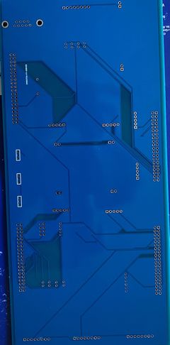
| − | == | + | == Hardware Integration: Printed Circuit Board == |
<br/> | <br/> | ||
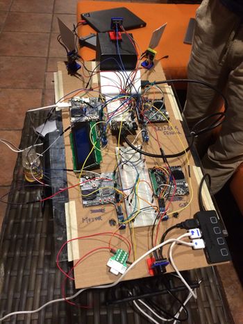
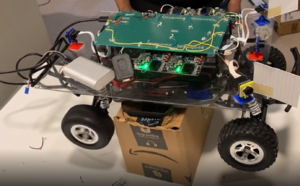
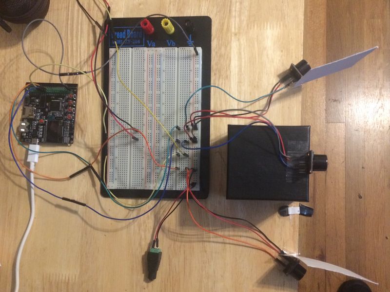
We Initially started with a very basic design of mounting all the hardware on a cardboard sheet for our first round of Integrated hardware testing. | We Initially started with a very basic design of mounting all the hardware on a cardboard sheet for our first round of Integrated hardware testing. | ||
<br/> | <br/> | ||
| − | <B> Challenges</b>: | + | [[File:Car_Chassis_Initial.jpg|thumb|350px|caption|center|First Prototype Board]]<BR/> |
| + | <br> | ||
| + | <B> Challenges</b>: The wires were an entire mess and the car could not navigate properly due to the wiring issues as all the wires were entangling and a few had connectivity issues. | ||
Hence we decided to go for a basic dot matrix Design before finalizing our final PCB Design as a Prototype board for testing if anything goes haywire. | Hence we decided to go for a basic dot matrix Design before finalizing our final PCB Design as a Prototype board for testing if anything goes haywire. | ||
<br/> | <br/> | ||
| − | |||
<br/> | <br/> | ||
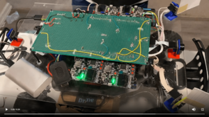
The Prototype Board just before the actual PCB board was created on a dot matrix PCB along with all the hardware components for the Intermediate Integrated testing phase is as follows: | The Prototype Board just before the actual PCB board was created on a dot matrix PCB along with all the hardware components for the Intermediate Integrated testing phase is as follows: | ||
<br/> | <br/> | ||
| − | [[File:Prototype_PCB_1.png | | + | {| style="margin-left: auto; margin-right: auto; border: none;" |
| − | [[File:Prototype_PCB_2.jpeg |thumb| | + | |[[File:Prototype_PCB_1.png|center|300px|thumb|Prototype board 1]] |
| − | < | + | | |
| − | <HR> | + | |[[File:Prototype_PCB_2.jpeg|center|300px|thumb|Prototype board 2]] |
| + | | | ||
| + | |[[File:Prototype_PCB_3.png|center|300px|thumb|Prototype board 3]] | ||
| + | | | ||
| + | |} | ||
| + | |||
| + | |||
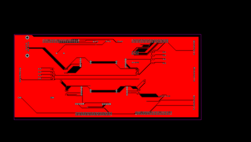
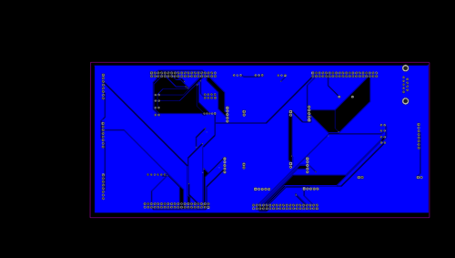
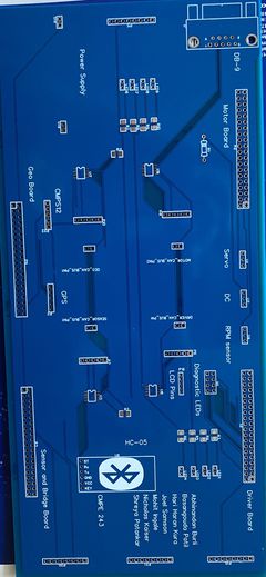
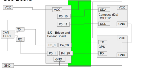
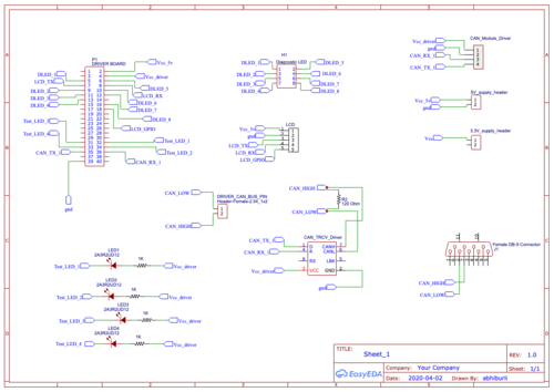
| + | 1) To avoid all the above challenges We designed the custom PCB using EasyEDA in which we implemented connections for all the controller modules(SJTwo Board LPC4078) all communicating/sending data via CAN bus. The data is sent by individual sensors to the respective controllers. GPS and Compass are connected to Geographical Controller. RPM sensor, DC and Servo Motors are connected to Motor Controller. <br> | ||
| + | 2) Ultrasonic sensors are connected to Bridge and Sensor Controller. LCD is connected to Driver Controller. Bluetooth is connected to Bridge and Sensor Controller. CAN Bus is implemented using CAN Transceivers SN65HVD230 terminated by 120 Ohms; with PCAN for monitoring CAN Debug Messages and Data. Some Components need 5V while some sensors worked on 3.3V power supply. Also it was difficult to use separate USB's to power up all boards.Hence we used CorpCo breadboard power supply 3.3V/5V. <br> | ||
| + | 3) PCB was sent to fabrication to JLCPCB China which provided PCB with MOQ of 5 with the lead time of 1 week. We implemented 2 layers of PCB with most of the parts in top layer GPS sensor and Compass sensor. We implemented rectangular header connector for SJTwo boards, RPM sensor, DC & Servo Motor on the bottom layer. There were 2 iterations of this board.<br> | ||
| + | 4) <b> Challenges: </b>We also need to change the header for LCD since it was having different pitch. | ||
| + | <br><br><br> | ||
| + | |||
| + | <B>Designing:</B> | ||
| + | {| style="margin-left: auto; margin-right: auto; border: none;" | ||
| + | |[[File:TopLayer.png|Left|500px|thumb|Top Layer development]] | ||
| + | | | ||
| + | |[[File:BottomLayer.png|Right|500px|thumb|Bottom Layer development]] | ||
| + | | | ||
| + | |} | ||
| + | <B>After Delivery:</B> | ||
| + | {| style="margin-left: auto; margin-right: auto; border: none;" | ||
| + | |[[File:after_delivery_top.jpg|Left|240px|thumb|Top Layer development]] | ||
| + | | | ||
| + | |[[File:after_delivery_bottom.jpg|Right|240px|thumb|Bottom Layer development]] | ||
| + | | | ||
| + | |} | ||
| + | <br> | ||
| + | <br> | ||
| + | <br> | ||
| + | <HR/> | ||
<BR/> | <BR/> | ||
== CAN Communication == | == CAN Communication == | ||
| − | + | ||
| + | CAN Communication is used to communicate between all the boards and it requires the bus to be terminated using two 120 Ohm resistors. CAN is a very deterministic broadcast bus. Based on the .dbc file, each module will transmit only selected messages. Receiving of the messages is enabled by filtering. The module can be configured to receive all messages or receive selected messages. Given below are features of CAN bus: | ||
| + | * Standard baud rate of 100K, 125K, 250K, 500k or 1M | ||
| + | * Differential Pair - Half-duplex | ||
| + | |||
| + | ==== Working of CAN bus ==== | ||
| + | A CAN frame has the following data: | ||
| + | * 4 bits for Data Length Code | ||
| + | * Remote Transmission Request | ||
| + | * ID extend bit | ||
| + | * Message ID (11 bit or 29 bit) | ||
| + | |||
| + | For CAN we require a transceiver(unlike) other BUSes. This transceiver converts the Rx and Tx lines to a single differential pair. where Logic 1( recessive) is represented by a ZERO volt difference and Logic 0(dominant) is represented by 2V difference. | ||
| + | |||
| + | '''Arbitration''' happens in can bus to make sure no two nodes are transmitting at the same time. A lower Message-ID has a Higher priority on the CAN bus since 0 is the dominant bit. | ||
| + | |||
| + | To make sure that a node does not put a lot of consecutive 1s or 0s together '''Bit Stuffing''' is done, where the CAN HW ''stuffs'' extra bits to improve CAN-BUS integrity. Our project's overall design is described below. | ||
=== Hardware Design === | === Hardware Design === | ||
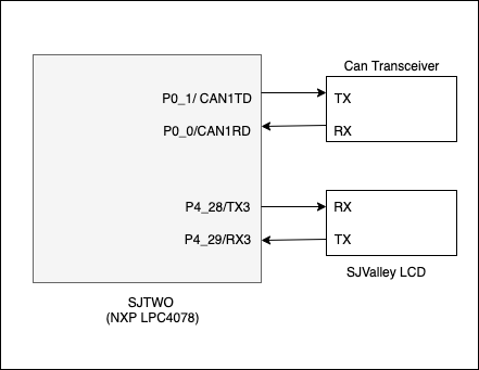
| − | + | We used the full CAN mode, to do hardware filtering and storage of messages. All the 4 boards Driver, GEO, Sensor and Bridge and Motor board communicate with each other over can messages. We connected a play and plug Waveshare CAN Transceivers Board for CAN Communication with our SjTwo Boards. This Board works on 3.3V and connects to the CAN Rx and CAN Tx Pins of the SjTwo Board. This Board then converts the signal to CAN High and CAN Low signal. This board itself has terminating resistors, thus when we connect 5 of them in one bus we bypass the terminating resistors present on the board itself and just use 120 ohms of terminating resistor at each end. This board has TI Chip installed on it and works flawlessly when interfaced with SjTwoboards. | |
| + | [[ File: CMPE243_S20_can_interface.png|frame|centre|600px|CAN Interface]] | ||
| + | |||
| + | ==== CAN Communication Table ==== | ||
| + | The table indicates the messages based on the transmitter. | ||
| + | |||
| + | {| class="wikitable" | ||
| + | |- | ||
| + | ! scope="col"| Sr. No | ||
| + | ! scope="col"| Message ID | ||
| + | ! scope="col"| Message function | ||
| + | ! scope="col"| Receivers | ||
| + | |- | ||
| + | |- | ||
| + | |- | ||
| + | |- | ||
| + | ! colspan="4"| Driver Controller Commands | ||
| + | |- | ||
| + | |- | ||
| + | |1 | ||
| + | |300 | ||
| + | |Driver Command for motor direction (forward/reverse), speed (m/hr) and steering direction for the motor. | ||
| + | |Motor, SENSOR_BRIDGE | ||
| + | |- | ||
| + | |2 | ||
| + | |900 | ||
| + | |Battery Percentage | ||
| + | |SENSOR_BRIDGE | ||
| + | |- | ||
| + | |- | ||
| + | ! colspan="4"| Bridge Sensor Controller Commands | ||
| + | |- | ||
| + | |- | ||
| + | |3 | ||
| + | |200 | ||
| + | |Obstacle Data for the front back left and right sensor | ||
| + | |DRIVER | ||
| + | |- | ||
| + | |4 | ||
| + | |101 | ||
| + | |CAR Action, Start and Stop state of car | ||
| + | |DRIVER | ||
| + | |- | ||
| + | |- | ||
| + | |5 | ||
| + | |500 | ||
| + | |Destination coordinate from google maps | ||
| + | |GEO | ||
| + | |- | ||
| + | |- | ||
| + | |6 | ||
| + | |700 | ||
| + | |Motor test button | ||
| + | |Motor | ||
| + | |- | ||
| + | |- | ||
| + | |7 | ||
| + | |800 | ||
| + | |Headlight state | ||
| + | |DRIVER | ||
| + | |- | ||
| + | |- | ||
| + | ! colspan="4"| Geo Controller Commands | ||
| + | |- | ||
| + | |- | ||
| + | |8 | ||
| + | |401 | ||
| + | |Current heading and destination heading angle and distance to destination from the GPS for driver. | ||
| + | |DRIVER, SENSOR_BRIDGE | ||
| + | |- | ||
| + | |9 | ||
| + | |801 | ||
| + | |Debug current latitude and longitude | ||
| + | |DRIVER | ||
| + | |- | ||
| + | |- | ||
| + | ! colspan="4"| Motor Controller Commands | ||
| + | |- | ||
| + | |- | ||
| + | |10 | ||
| + | |600 | ||
| + | |Debug motor to show current speed and PWM value | ||
| + | |DRIVER, SENSOR_BRIDGE | ||
| + | |- | ||
| + | |- | ||
| + | |- | ||
| + | |} | ||
=== DBC File === | === DBC File === | ||
[https://gitlab.com/bucephalus/sjtwo-c/-/blob/dev/integrate/dbc/project.dbc DBC File ] | [https://gitlab.com/bucephalus/sjtwo-c/-/blob/dev/integrate/dbc/project.dbc DBC File ] | ||
| + | <syntaxhighlight lang="c"> | ||
| + | VERSION "" | ||
| + | |||
| + | NS_ : | ||
| + | BA_ | ||
| + | BA_DEF_ | ||
| + | BA_DEF_DEF_ | ||
| + | BA_DEF_DEF_REL_ | ||
| + | BA_DEF_REL_ | ||
| + | BA_DEF_SGTYPE_ | ||
| + | BA_REL_ | ||
| + | BA_SGTYPE_ | ||
| + | BO_TX_BU_ | ||
| + | BU_BO_REL_ | ||
| + | BU_EV_REL_ | ||
| + | BU_SG_REL_ | ||
| + | CAT_ | ||
| + | CAT_DEF_ | ||
| + | CM_ | ||
| + | ENVVAR_DATA_ | ||
| + | EV_DATA_ | ||
| + | FILTER | ||
| + | NS_DESC_ | ||
| + | SGTYPE_ | ||
| + | SGTYPE_VAL_ | ||
| + | SG_MUL_VAL_ | ||
| + | SIGTYPE_VALTYPE_ | ||
| + | SIG_GROUP_ | ||
| + | SIG_TYPE_REF_ | ||
| + | SIG_VALTYPE_ | ||
| + | VAL_ | ||
| + | VAL_TABLE_ | ||
| + | |||
| + | BS_: | ||
| + | |||
| + | BU_: DBG DRIVER MOTOR SENSOR_BRIDGE GEO | ||
| + | |||
| + | BO_ 101 CAR_ACTION: 1 SENSOR_BRIDGE | ||
| + | SG_ CAR_ACTION_cmd : 0|8@1+ (1,0) [0|0] "" DRIVER | ||
| + | |||
| + | BO_ 200 SENSOR_USONARS: 5 SENSOR_BRIDGE | ||
| + | SG_ SENSOR_USONARS_left : 0|10@1+ (1,0) [0|0] "cm" DRIVER | ||
| + | SG_ SENSOR_USONARS_right : 10|10@1+ (1,0) [0|0] "cm" DRIVER | ||
| + | SG_ SENSOR_USONARS_front : 20|10@1+ (1,0) [0|0] "cm" DRIVER | ||
| + | SG_ SENSOR_USONARS_back : 30|10@1+ (1,0) [0|0] "cm" DRIVER | ||
| + | |||
| + | BO_ 300 DRIVER_STEER_SPEED: 2 DRIVER | ||
| + | SG_ DRIVER_STEER_direction : 0|8@1- (1,0) [-2|2] "" MOTOR, SENSOR_BRIDGE | ||
| + | SG_ DRIVER_STEER_move_speed: 8|8@1- (1,0) [-10|10] "" MOTOR, SENSOR_BRIDGE | ||
| + | |||
| + | BO_ 401 GEO_COMPASS: 6 GEO | ||
| + | SG_ GEO_COMPASS_current_heading : 0|16@1+ (1E-002,0) [0|360.01] "degree" DRIVER, SENSOR_BRIDGE | ||
| + | SG_ GEO_COMPASS_desitination_heading : 16|16@1+ (1E-002,0) [0|360.01] "degree" DRIVER, SENSOR_BRIDGE | ||
| + | SG_ GEO_COMPASS_distance: 32|16@1+ (1E-002,0) [0.01|255.01] "m" DRIVER, SENSOR_BRIDGE | ||
| + | |||
| + | BO_ 500 BRIDGE_GPS: 8 SENSOR_BRIDGE | ||
| + | SG_ BRIDGE_GPS_latitude : 0|32@1- (1E-006,-90.0) [-90.0|90.0] "" GEO | ||
| + | SG_ BRIDGE_GPS_longitude : 32|32@1- (1E-006,-180.0) [-180.0|180.0] "" GEO | ||
| + | |||
| + | BO_ 600 MOTOR_SPEED: 4 MOTOR | ||
| + | SG_ MOTOR_SPEED_info : 0|16@1- (0.01,-30.01) [-30.01|30.01] "mph" DRIVER, SENSOR_BRIDGE | ||
| + | SG_ MOTOR_SPEED_pwm : 16|16@1+ (0.01, 0) [0.01|20.01] "pwm" DRIVER, SENSOR_BRIDGE | ||
| + | |||
| + | BO_ 700 TEST_BUTTON: 1 SENSOR_BRIDGE | ||
| + | SG_ TEST_BUTTON_press : 0|8@1+ (1,0) [0|0] "" MOTOR | ||
| + | |||
| + | BO_ 800 HEADLIGHT: 1 SENSOR_BRIDGE | ||
| + | SG_ HEADLIGHT_SWITCH : 0|8@1+ (1,0) [0|0] "" DRIVER | ||
| + | |||
| + | BO_ 900 BATTERY: 1 DRIVER | ||
| + | SG_ BATTERY_PERCENTAGE : 0|8@1+ (1,0) [0|100] "percent" SENSOR_BRIDGE | ||
| + | |||
| + | |||
| + | CM_ BU_ DRIVER "The driver controller driving the car"; | ||
| + | CM_ BU_ MOTOR "The motor controller of the car"; | ||
| + | CM_ BU_ SENSOR_BRIDGE "The sensor and bridge controller of the car"; | ||
| + | CM_ BU_ GEO "The geo controller of the car"; | ||
| + | CM_ BO_ 100 "Sync message used to synchronize the controllers"; | ||
| + | CM_ SG_ 100 DRIVER_HEARTBEAT_cmd "Heartbeat command from the driver"; | ||
| + | |||
| + | BA_DEF_ "BusType" STRING ; | ||
| + | BA_DEF_ BO_ "GenMsgCycleTime" INT 0 0; | ||
| + | BA_DEF_ SG_ "FieldType" STRING ; | ||
| + | |||
| + | BA_DEF_DEF_ "BusType" "CAN"; | ||
| + | BA_DEF_DEF_ "FieldType" ""; | ||
| + | BA_DEF_DEF_ "GenMsgCycleTime" 0; | ||
| + | |||
| + | BA_ "GenMsgCycleTime" BO_ 100 1000; | ||
| + | BA_ "GenMsgCycleTime" BO_ 200 50; | ||
| + | BA_ "FieldType" SG_ 100 DRIVER_HEARTBEAT_cmd "DRIVER_HEARTBEAT_cmd"; | ||
| + | |||
| + | BA_ "FieldType" SG_ 300 DRIVER_STEER_direction "DRIVER_STEER_direction"; | ||
| + | |||
| + | |||
| + | VAL_ 300 DRIVER_STEER_direction -2 "DRIVER_STEER_direction_HARD_LEFT" -1 "DRIVER_STEER_direction_SOFT_LEFT" 0 "DRIVER_STEER_direction_STRAIGHT" 1 "DRIVER_STEER_direction_SOFT_RIGHT" 2 "DRIVER_STEER_direction_HARD_RIGHT" ; | ||
| + | |||
| + | </syntaxhighlight> | ||
| + | ===Technical Challenges === | ||
| + | '''Negative Floating point numbers was not supported by auto code generator''' | ||
| + | |||
| + | The auto code generator only supported positive floating-point numbers, so we added a negative offset equivalent to the minimum negative value to propagate the negative values. | ||
| + | |||
| + | ""Auto-generated code used to generate double constants instead of float constants"" | ||
| + | |||
| + | We modified the auto generator script to generate the float constants in place of double constant. As double constant were not supported by hardware that would increase the complexity of code. | ||
<HR> | <HR> | ||
<BR/> | <BR/> | ||
| − | == Bridge and Sensor Controller == | + | ==<font color="0000FF"> Bridge and Sensor Controller: Bluetooth Module </font>== |
| − | < | + | Control signals from the android application were transmitted to the car using Bluetooth. |
| + | From the bridge and sensor board, debug information (decoded CAN messages) were transmitted to the android application in real-time. | ||
| + | |||
| + | ===<font color="0000FF"> Hardware Design </font>=== | ||
| + | HC-05 module is an easy to use Bluetooth SPP (Serial Port Protocol) module, designed for wireless serial connection setup. It works on 2.4GHz radio transceiver frequency. The HC05 module has two operating modes - AT mode and User mode. In order to enter AT mode the manual switch on the board must be pressed for about 4 seconds. The LED display sequence on the board changes indicating successful entry to AT mode. Using AT commands various factors such as baud rate, auto-pairing, security features can be configured. | ||
| + | |||
| + | '''Most commonly used AT commands –''' | ||
| + | |||
| + | • AT+VERSION – Get module version number | ||
| + | <br>• AT+ADDR – Module address. Save the slave address for paring with the master module | ||
| + | <br>• AT+ROLE – 0 indicates slave module and 1 indicates Master module. | ||
| + | <br>• AT+PSWD – Set password for the module using this AT command. | ||
| + | <br>• AT+UART – Select the device baud rate from 9600,19200,38400,57600,115200,230400,460800 | ||
| + | <br>• AT+BIND – Bind Bluetooth address | ||
| + | |||
| + | Once the desired configurations are set, reset the module to switch back to User mode. | ||
| + | |||
| + | '''Hardware Features -''' | ||
| + | |||
| + | • Low Power Operation - 1.8 to 3.6V I/O | ||
| + | <br>• UART interface with programmable baud rate | ||
| + | <br>• Programmable stop and parity bits | ||
| + | <br>• Auto - pairing with last connected device | ||
| + | |||
| + | '''Pin Connections -''' | ||
| + | [[File:Bluetooth_HC055.png|thumb|450px|caption|center|Source: https://components101.com]] | ||
| + | |||
| + | <center> | ||
| + | |||
| + | {| class="wikitable middle" | ||
| + | |- | ||
| + | ! scope="col"| HC05 | ||
| + | ! scope="col"| SJ2 Board | ||
| + | |- | ||
| + | ! scope="row"| Vcc | ||
| + | | 3.3 volts | ||
| + | |- | ||
| + | ! scope="row"| Gnd | ||
| + | | Gnd | ||
| + | |- | ||
| + | ! scope="row"| Rx | ||
| + | | GPIO4 Pin 28 | ||
| + | |- | ||
| + | ! scope="row"| Tx | ||
| + | | GPIO4 Pin 29 | ||
| + | |- | ||
| + | |} | ||
| + | </center> | ||
| + | |||
| + | ===<font color="0000FF"> Software Design </font>=== | ||
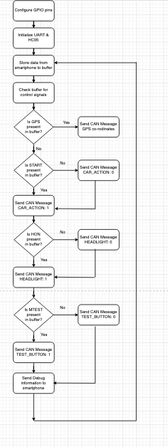
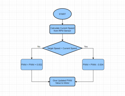
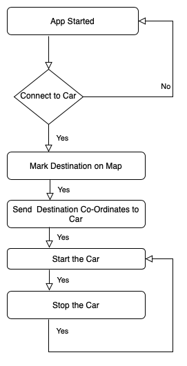
| + | [[File:Screenshot 2020-05-22 at 5.19.09 PM.png|thumb|500px|caption|center|Flowchart]] | ||
| + | |||
| + | '''Software Design Flow -''' | ||
| + | <br> 1) Initialize UART | ||
| + | <br> 2) Check the control signals in buffer and send appropriate CAN message | ||
| + | <br> 3) Send debug information to the application | ||
| + | |||
| + | Configure the GPIO pin functionality to UART using the gpio_construct_with_function API. Set the baud rate and the Queue size. The queue size should be set by calculating the periodic callback frequency and the speed at which data is being received and dequeued from the buffer. The baud rate of the UART set in SJ2 should be equal to the baud rate in HC05 board. The control signal data is continuously being received and stored in the UART queue created. Every 10hz (100ms), the data stored in the queue is removed and stored in the circular buffer. A valid data check is made and if valid data is present in the circular buffer, we check if any valid control signal is present in the buffer. The valid format for the GPS co-ordinate begins with the pattern ‘*GPS’ and ends with ‘#’. Once the GPS string is extracted successfully from the buffer, an API call is made to extract the correct latitude and longitude from the string. Similarly, all the other control signals have a valid format. Once a control signal is detected we extract the signal from the buffer, set a flag and send the respective CAN message to other boards. When the CAN message is sent it is important to erase that message from the buffer to avoid any unnecessary action in the next periodic callback. Using the sl_string library, the message was removed from the buffer and the rear index was adjusted based on the length of the signal. In the 10hz periodic callback function, debug information was also being sent in real-time to the android application. On the bridge and sensor board, all the CAN messages from other board were decoded. A list of all the debug information sent to the application is given below. | ||
| + | |||
| + | '''List of debug information sent to the android application –''' | ||
| + | Ping Status | ||
| + | Car Action | ||
| + | Motor Speed | ||
| + | Motor Speed PWM | ||
| + | Ultrasonic left | ||
| + | Ultrasonic right | ||
| + | Ultrasonic back | ||
| + | Ultrasonic front | ||
| + | Geo compass current heading | ||
| + | Geo compass destination heading | ||
| + | Geo compass compass distance | ||
| + | Driver Steer Speed | ||
| + | Driver Steer Direction | ||
| + | Headlight | ||
| + | Test Button | ||
| + | GPS Latitude | ||
| + | GPS Longitude | ||
| + | Battery Percentage | ||
| + | |||
| + | ===<font color="0000FF"> Technical Challenges </font>=== | ||
| + | '''Creating Dynamic Buffer''' | ||
| + | |||
| + | From the android application the sensor board was receiving multiple control signals such as START, STOP, HON, HOFF, MTEST and GPS co-ordinates. The order in which these control signals were sent from the android application was not static. Hence it was necessary to create a dynamic circular buffer algorithm that will handle this scenario. Once a particular control signal was detected, the appropriate CAN message was sent and the signal was erased from the buffer to avoid unnecessary action in the next periodic callback. Changing the front index of the buffer once the signal was erased and moving other data present in the buffer was a difficult task. This was solved by getting the start index of the control message in the buffer, finding the size of the signal in bytes and overwriting that signal with other data present in the buffer from that particular start index using APIs from the sl_string library. | ||
| + | |||
| + | ==<font color="0000FF"> Bridge and Sensor Controller: Sensors </font>== | ||
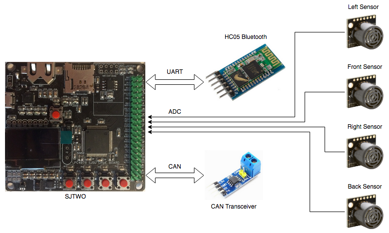
| + | The sensor part of the bridge and sensor controller board is responsible for receiving the sensor readings, converting them to centimeters, and then sending them to the driver controller board over CAN. A total of four Maxbotix MaxSonar HRLV-EZ0 ultrasonic sensors are connected to the bridge and sensor controller; three in front and one in back. | ||
| + | |||
| + | [[File:Bridge_and_Sensor_Controller_Diagram.png|center|800px|thumb|Bridge and Sensor Controller Diagram]] | ||
| + | |||
| + | We decided to use four ultrasonic sensors due to their relatively easy setup process, ranging capabilities, and reliability. We considered using lidar, but these sensors rely on additional factors such as lighting conditions. We specifically chose Maxbotix’s more expensive MaxSonar line because of their greater accuracy over their standard counterparts. The MaxSonar sensors have internal filtering to greatly reduce the amount of external noise affecting your sensor readings, making your readings far more reliable. The MaxSonar sensors also include an on-board temperature sensor to automatically adjust the speed of sound value based on the temperature of the environment the sensors are being used in. This means the sensor readings will stay consistent regardless of the weather and time of day (night time is much cooler than during the day). | ||
| + | |||
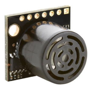
| + | Maxbotix offers ultrasonic sensors with different beam widths, and we chose their EZ0 sensors because they have the widest beam. Initially we thought this was a good idea because wider beams means an increased detection zone and less blind spots (width-wise). Please refer to the Technical Challenges section for details as to why we don’t recommend getting the widest possible beam for all four sensors. | ||
| + | |||
| + | [[File:MaxBotix_MB1003_HRLV_MaxSonar_EZ0_Sensor.png|center|300px|thumb|MaxBotix MB1003 HRLV MaxSonar EZ0 Sensor]] | ||
| + | |||
| + | ===<font color="0000FF"> Hardware Design </font>=== | ||
| + | The ultrasonic sensors are powered using +5V, and connected to the SJtwo board’s ADC pins. There are only 3 available exclusively ADC pins on the SJtwo board, and so we changed the DAC pin to ADC mode in our ADC driver since we needed a total of 4 ADC pins. We left the RX pin of each sensor unconnected, and so each sensor ranges continuously and independently of one another. We don’t recommend doing this because the sensor beams interfere with each other when firing at the same time, but due to implementation issues, we weren’t able to use the RX pin approach. Please refer to the Technical Challenges section for details as to what problems we encountered when using the RX pin, and how we resolved the interference problems as a result of not using the RX pin. | ||
| + | |||
| + | [[File:Bridge_Sensor_Controller_Schematic.png|center|1100px|thumb|Bridge and Sensor Controller Schematic]] | ||
| + | |||
| + | ====Sensor Operating Voltage==== | ||
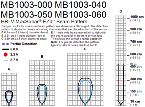
| + | The specific sensors we chose have an operating voltage requirement of +2.5V to +5.5V. Shown below from the MaxBotix datasheets is the detection pattern based on three different operating voltages. The detection zone decreases slightly as the operating voltage is decreased. | ||
| + | |||
| + | [[File:Ultrasonic_Sensor_Beam_Pattern.png|center|500px|thumb|Ultrasonic Sensor Beam Pattern]] | ||
| + | |||
| + | Additionally, the strength of the sound wave generated by the ultrasonic sensor decreases as the operating voltage decreases. A weaker sound wave means less sound “bouncing” back to the sensor, which can result in obstacles not getting detected, especially with softer surfaces like people and small plants, or thinner objects like railed gates or metal pipe handrails. We encountered this problem when using an operating voltage of 3.3V. Even though the distance the sensors could detect when powered with 3.3V was perfectly sufficient for our application, the sensors wouldn’t consistently detect softer and thinner obstacles (mainly people and thin pipes/rails). Choosing an operating voltage of 5V drastically improved the detection abilities of the sensors. The sensors consistently detected people, thin pipes sticking out of the ground, thin railed gates, metal pipe handrails, and plants that were at or above the mounting height of the sensors. | ||
| + | |||
| + | ====Sensor Mounts and Shields==== | ||
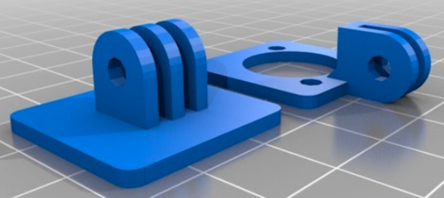
| + | In order to secure the sensors to the car chassis, we 3D printed sensor mounts for all four of the ultrasonic sensors. The sensor mounts are adjustable so that the nozzle of the sensor can be adjusted upward or downward. It was extremely helpful to have adjustable mounts because it took quite a bit of testing and trial and error to find the angle that the sensor nozzle needed to be tilted upward in order to detect correctly. If the sensor nozzle wasn’t pointed up high enough, the sensors would detect the road as an obstacle. We placed screws inside the mounting base hole to ensure the mount wouldn’t tilt out of position, and screwed the sensor into the mount to keep it from falling out or jiggling around. Shown below is the sensor mount design in CAD software. | ||
| + | |||
| + | [[File:Sensor_Mount_in_CAD_Software.png|center|500px|thumb|Sensor Mount in CAD Software]] | ||
| + | |||
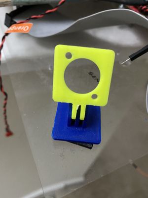
| + | Once 3D printed, the two pieces of the mount are fit together. | ||
| + | |||
| + | [[File:Printed_Sensor_Mount.jpg|center|300px|thumb|Printed Sensor Mount]] | ||
| + | |||
| + | In addition to sensor mounts, we put adjustable sensor shields onto the car chassis in order to prevent beam interference between the left, right, and front sensors. When all sensors are firing, sometimes one of them would detect another sensor’s beam, resulting in a false reading. Adding shields greatly reduced the occurrence of a sensor detecting another sensor’s beam, and reduced the severity to which it affected the reading. | ||
| + | |||
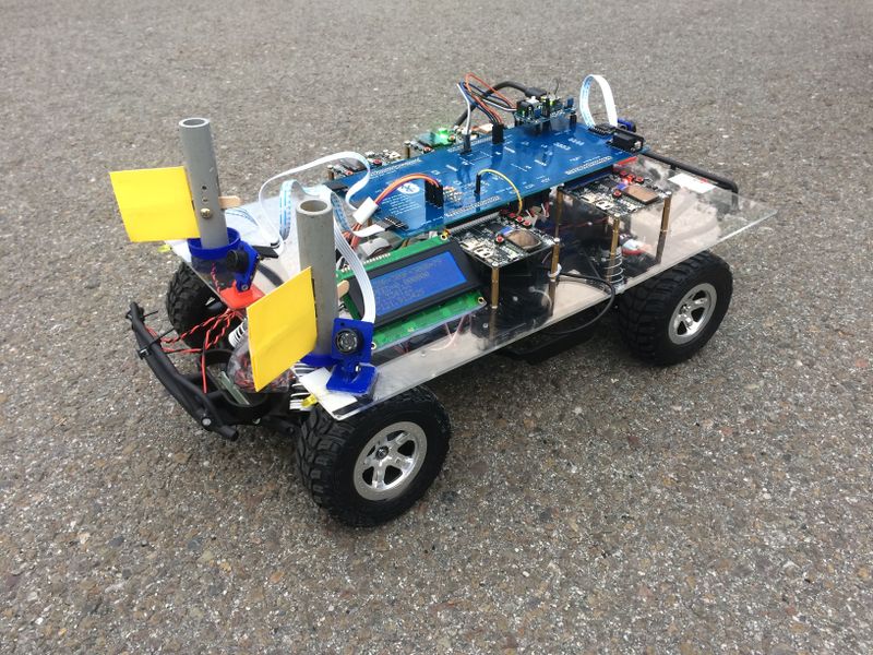
| + | Unfortunately, due to the Coronavirus situation we did not have access to a 3D printer and were unable to print custom designed sensor shields (the sensor mounts were 3D printed before the Coronavirus shelter-in-place happened). To make shields, we cut rectangular pieces of cardboard (yellow cardboard for aesthetics) and hot glued them each to a popsicle stick. We drilled slits into some pvc pipe and placed the popsicle stick end of the shield inside. Screws were used to tighten down the popsicle stick and keep the shield in place. The pipe pieces were hot glued to plastic bottle caps, which were then screwed into the car chassis acrylic sheet. The shields can be adjusted left or right by twisting the bottle cap screwed to the acrylic sheet, and can be adjusted up or down by pushing up or pulling down on the popsicle stick end of the shield. The adjustable sensor shields and mounts on the car chassis are shown below. | ||
| + | |||
| + | [[File:Sensor_Mounts_and_Shields_on_Car_Chassis.jpg|center|800px|thumb|Sensor Mounts and Shields on Car Chassis]] | ||
| + | |||
| + | ====Placement on Chassis==== | ||
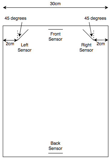
| + | All four ultrasonic sensors were placed in their mounts, and then the bottom of the mount was hot glued to the acrylic sheet mounted on the car chassis. The placement of the sensors was an important decision to make because placing them too close together or not angling the left and right sensors outward enough resulted in beam interference. | ||
| + | |||
| + | A trial and error approach was taken to find the best sensor placement configuration for the left, right, and front sensors. The sensors were taped to the edge of a desk and the readings were observed to see if the values were stable or if the beams were interfering with each other. The testing setup used to determine the best sensor placement configuration can be seen below. | ||
| + | |||
| + | [[File:Ultrasonic_Sensor_Placement_Testing_Setup.jpg|center|800px|thumb|Ultrasonic Sensor Placement Testing Setup]] | ||
| + | |||
| + | Through testing, it was determined that angling the left and right sensors outward at about 45 degrees, and placing them as far apart as possible on the acrylic sheet produced good results. The front and back sensors were centered on the acrylic sheet. | ||
| + | |||
| + | [[File:Ultrasonic_Sensor_Placement_on_Acrylic_Sheet.png|center|500px|thumb|Ultrasonic Sensor Placement on Acrylic Sheet]] | ||
| + | |||
| + | ===<font color="0000FF"> Software Design </font>=== | ||
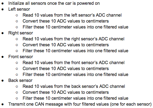
| + | The software design of the sensor modules consisted of the following ordered steps. | ||
| + | |||
| + | [[File:Sensor_Software_Design_Steps.png|center|800px|thumb|Sensor Software Design Steps]] | ||
| + | |||
| + | The flowchart below is for a single sensor between the initialization step, and the send CAN message step. The three in-between steps are done a total of four times (for each sensor). To keep things clean and easy to understand, the flowchart only shows the steps for a single sensor. | ||
| + | |||
| + | [[File:Single Sensor Flowchart.png|center|500px|thumb|Single Sensor Flowchart]] | ||
| + | |||
| + | ====Initializing the Sensors==== | ||
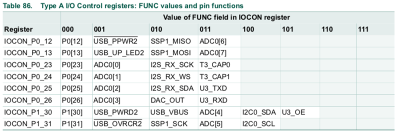
| + | Some initialization and ADC driver modifications were required in order to get our sensors up and running. First, we wanted to use the analog out pin to receive data from all four sensors due to the simplicity of this interface. Since the Sjtwo board only has 3 available header pins with ADC functionality, we read the user manual for the LPC4058 [insert reference to user manual?] in order to see if any other available header pins had ADC capabilities. Shown below is Table 86 in the user manual, which lists all pins that have ADC functionality. Comparing this table with our SJtwo board, we found that ADC channel 3 located on P0[26] (labeled as DAC on SJtwo board) could be used as our fourth ADC pin. | ||
| + | |||
| + | [[File:Table 86 in LPC4058 User Manual.png|center|800px|thumb|Table 86 in LPC4058 User Manual]] | ||
| + | |||
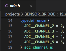
| + | We modified the existing ADC driver in order to add support for P0[26] as an ADC pin. An enumeration for ADC channel 3 was added to adc.h, and ADC channel 3 was added to the “channel check” if statement in adc.c’s adc__get_adc_value(...) function. These modifications are shown below. | ||
| + | |||
| + | [[File:Adc.h Modification.png|center|300px|thumb|adc.h Modification]] | ||
| + | |||
| + | [[File:Adc.c Modification in adc__get_adc_value(...).png|center|800px|thumb|adc.c Modification in adc__get_adc_value(...)]] | ||
| + | |||
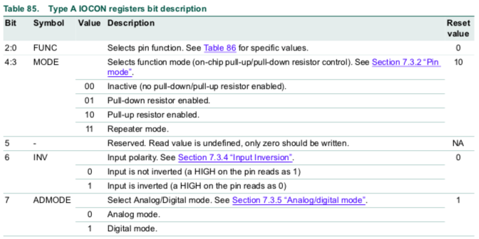
| + | In order to begin reading values from the sensors, all ADC pins must be set to “Analog Mode”. Looking at Table 85 in the LPC4058 user manual, we can see that upon reset, all ADC pins are in “Digital Mode”. | ||
| + | |||
| + | [[File:Part of Table 85 in LPC4058 User Manual.png|center|800px|thumb|Part of Table 85 in LPC4058 User Manual]] | ||
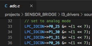
| − | === | + | The SJtwo board’s ADC pins will not work if they are not set to “Analog Mode”, and so this code had to be added to the existing ADC driver since it was missing. We did the following IOCON register bit 7 clearing for all ADC pins inside the adc__initialize(...) function. |
| + | |||
| + | [[File:Adc.c_Modification_in_adc_initialize(...).png|center|300px|thumb|Adc.c Modification in adc_initialize(...).png]] | ||
| + | |||
| + | Once the modifications to the existing ADC driver had been made, we called adc__initialize(...) in our periodic_callbacks_initialize(...) function in order to perform the initialization of our ADC interface. | ||
| + | |||
| + | ====Converting to Centimeters==== | ||
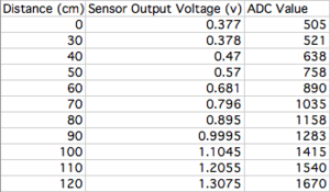
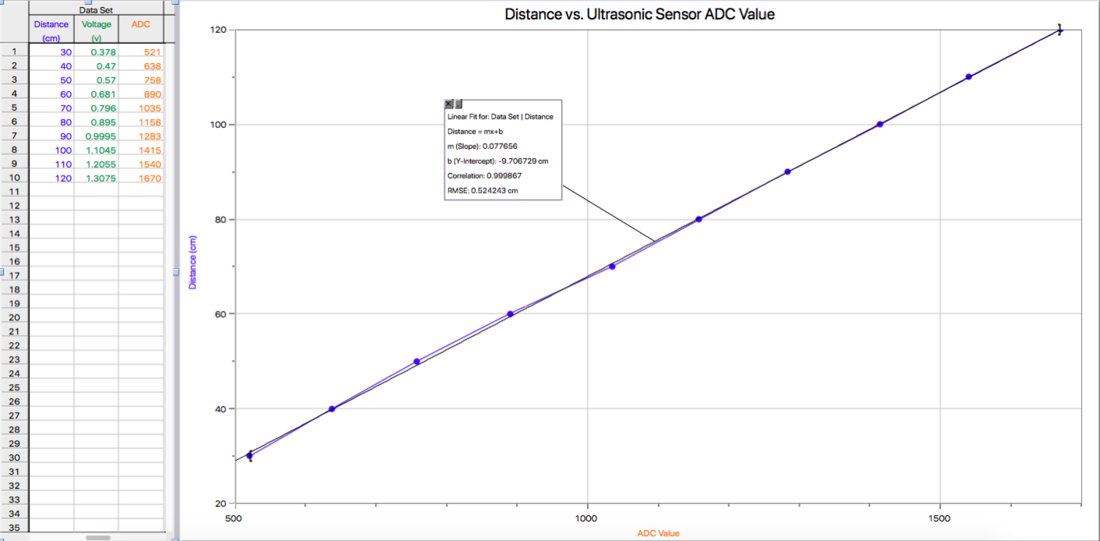
| + | The raw ADC values read from each sensor aren’t inherently meaningful, and so they must be converted to centimeters in order to gauge the distance of obstacles. In order to perform the conversion, we sampled and recorded a sensor’s raw ADC values with obstacles placed at distances ranging from 0cm to 120cm in increments of 10cm. We decided to stop at 120cm because the process of collecting the sensor’s data was very time consuming and our maximum threshold value was 110cm, so there was no need to go farther. Shown below are the measurements gathered for our particular sensor model. It should be noted that the sensors produce a range of values when detecting an obstacle at a given distance, and so we averaged the values to obtain the most accurate results. | ||
| + | |||
| + | [[File:Ultrasonic_Sensor_Measurements.png|center|300px|thumb|Ultrasonic Sensor Measurements]] | ||
| + | |||
| + | The values were plotted in a distance (Y-axis) versus ADC value (X-axis) graph, and a curve fit was performed in order to generate distance as a function of an ADC value. We used an application called Logger Pro because of its ability to automatically generate a curve fit for your data set. | ||
| + | |||
| + | [[File:Ultrasonic_Sensor_Distance_vs._ADC_Graph.png|center|1100px|thumb|Ultrasonic Sensor Distance vs. ADC Graph]] | ||
| + | |||
| + | We implemented the curve fit function generated by Logger Pro into code in order to convert our sensor’s ADC values to centimeters right after they were read from their respective ADC channel. | ||
| + | |||
| + | ====Filtering ==== | ||
| + | Occasionally, the sensors will report incorrect values due to internal or external noise. Getting sensors that are more expensive usually decreases the number of times this happens, but even one incorrect reading can be a problem. For example, a sensor reading may incorrectly dip below the threshold and detect an obstacle even when there is none. Or worse, an obstacle may be within the threshold range but the sensor reading doesn’t reflect an obstacle being detected. Both of these scenarios can be avoided by filtering the sensor values before sending them to the driver controller over CAN. | ||
| + | |||
| + | The problem we were facing before filtering was the following; when setting up an obstacle in front of a sensor a certain distance away, 80cm for example, we monitored the sensor values to make sure all the readings were within a couple centimeters of 80cm. We noticed that occasionally, the output sensor readings would look something like “...80, 81, 80, 79, 82, 80, 45, 80, 78, 83, 81, 80, 79, 80…”. The sudden drop to 45 is clearly an incorrect reading because the obstacle remained at a constant 80cm away the entire time. | ||
| + | |||
| + | We considered several different filtering algorithms such as Mean, Median, Mode, and Kalman Filter. The Kalman Filter is very complex and so we didn’t feel the need to use it since other simpler options would work just as well for our application. The Mean Filter was completely out of the question because it averages the values. We want to remove the incorrect value, not incorporate it into the filtered value. The Median Filter requires the input values to be sorted in ascending order, which increases the run time and may cause us to run past our time slot in the 50Hz periodic callback function. Ultimately, we decided to use the Mode Filter because of its simplicity, short run time, and doesn’t require input values to be sorted. Choosing a filtering algorithm that has a short run time was one of the most important considerations because the sensors are running in a fast periodic callback function. | ||
| + | |||
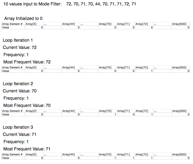
| + | We implemented our own Mode Filter algorithm that took a number of input sensor values that have been converted to centimeters, finds the mode (most frequently occurring value) of the values, and then returns the mode as the filtered value. Through testing, we found that using an input size of 10 values to the mode filter was perfectly sufficient. A list of possible input values and the mode filter output can be seen below to better illustrate how our mode filter implementation works. | ||
| + | |||
| + | [[File:Mode_Filter_Output.png|center|800px|thumb|Mode Filter Output]] | ||
| + | |||
| + | A corner-case that we needed to address was the possibility of multiple modes. This case can be seen in lines 2, 3, and 5 in the table above. We chose to return the mode that was most recent in order to reflect the most recent changes in sensor values. Take line 5 for example; all values occur exactly twice, which means there are five modes. The mode returned is 69 because it is the most recent mode. | ||
| + | |||
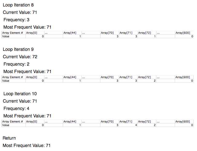
| + | As for the actual implementation of the Mode Filter, we based it off of the Counting Sort algorithm’s “bucket storing method” with some modifications in order to make the runtime O(n), with n being the input data size (10 in our case). There is no need to sort the values for our Mode Filter, and so the sorting part of the Counting Sort algorithm is completely omitted. The idea of storing the occurence of each value in an array element number equal to the current sensor value (in centimeters) is the only idea we used from the Counting Sort algorithm. An example of how our Mode Filter works can be seen below. | ||
| + | |||
| + | [[File:Mode_Filter_Iterations_(1).png|center|800px|thumb|Mode Filter Iterations (1)]] | ||
| + | |||
| + | [[File:Mode_Filter_Iterations_(2).png|center|800px|thumb|Mode Filter Iterations (2)]] | ||
| + | |||
| + | [[File:Mode_Filter_Iterations_(3).png|center|800px|thumb|Mode Filter Iterations (3)]] | ||
| + | |||
| + | The size of the array inside the Mode Filter algorithm is specifically set to 600 elements. The array needs to have element numbers for every possible sensor value (in centimeters). Our sensor values range is from 0 to 500 centimeters and so we added an extra 100 just for safety, which gives us a total of 600 array elements. This is the reason we chose to convert our sensor values to centimeters before passing them as input into the Mode Filter. If we were to pass the raw sensor values into the filter, we would need an array with around 4096 elements (SJtwo board’s ADC is 12-bit, so 2^12 = 4096). | ||
| + | |||
| + | ===<font color="0000FF"> Technical Challenges </font>=== | ||
| + | |||
| + | ====ADC==== | ||
| + | Three main problems occurred relating to our ADC interface. First, we were unable to get the sensors to output anything besides its maximum value. We checked the voltage on the ADC pin for multiple sensors and found that instead of increasing as an object got farther away, the voltage stayed constant. We concluded that since this was happening for all the sensors we tested, it must be a problem with our initialization code. After reading the ADC section in the user manual for our SJtwo board’s processor, we realized that our ADC driver was missing one thing. For each GPIO pin being used as an ADC pin, Pin 7 of the IOCON register has to be set to “ADC Mode”. After making this change, our sensors worked like a charm. | ||
| + | |||
| + | Next, we observed that our maximum sensor values weren’t the advertised 500cm. We experimented by putting obstacles in front of a sensor at varying distances and found that 300cm was the farthest the sensor could range. After reading the user manual for our SJtwo board’s processor, we realized that its ADC module operates in reference to 3.3V. We then switched to powering our sensors with 3.3V instead of 5V, hoping to get the 500cm range as advertised. This created the problem discussed below. | ||
| + | |||
| + | Our third problem we encountered was after making the switch from powering our sensors with 5V to 3.3V. 3.3V did not supply our sensors with enough power, and so we experienced large blind spots in our detection zone, and very inconsistent sensor readings due to the sensors generating weak sound waves from a lack of sufficient power. We decided to go back to powering our sensors with 5V since 300cm was more than enough ranging capability for this project. | ||
| + | |||
| + | ====Inconsistent Sensor Readings==== | ||
| + | When we first started testing the sensors, we used a single sensor to make sure our connections and code initialization was correct. We placed a flat object in front of the sensor at the same distance for a very long time to see how consistent our sensor readings were. We noticed that sometimes one reading would be very low or very high compared to the other readings. After doing some research, we found that this is a very common occurrence among sensors and can be resolved by filtering. We chose to implement our own filtering algorithm, which takes in a certain number of raw sensor values, finds the mode, and returns this as the filtered sensor value. | ||
| + | |||
| + | ====Slow Response to Obstacles==== | ||
| + | When we first began testing obstacle detection, we used one LED for each sensor for diagnostic testing purposes. If a sensor detected an obstacle, then its corresponding LED would turn on. When the obstacle was no longer present, the LED would turn off. We noticed that the response of the LED was very slow, and the sensor values in Busmaster would not change immediately when an obstacle was present. We solved this by moving our “get sensor values” code from 10Hz to 50Hz in order to get a faster obstacle detection response. | ||
| + | |||
| + | Additionally, when we started testing our PID acceleration, we noticed that the car would not stop in time before hitting an obstacle when moving at faster speeds. We monitored the sensor values on the android app to try and troubleshoot the issue. We found that the sensor values were not changing quick enough, and so the car was crashing because it didn’t have enough time to stop. We solved this problem by removing our “light up SJtwo board’s LEDs” function from our sensor’s CAN transmit function, which was slowing down the transmission of the sensor’s CAN messages. | ||
| + | |||
| + | ====Detecting Obstacles when None are Present==== | ||
| + | During our initial drive testing, our car would randomly take a sharp turn or stop when there were no obstacles in range. We hooked up Busmaster to the car’s on-board PCAN dongle and walked alongside the car while it was moving in order to diagnose the issue. We saw that the sensor values were dropping below the threshold when there were no obstacles present, and even when the car was not moving. This meant that the sensors were detecting the road or even parts of the car. We resolved this by tilting the sensor heads upwards until the sensor values were at their maximum (300cm for us). | ||
| − | === | + | ====Sensor's TX/RX Pins Not Working==== |
| − | + | Our first approach to solving sensor interference issues was to fire the sensor beams one at a time, and only after the previous sensor had finished. This functionality is built into MaxBotix sensors through the TX and RX pins. If these pins are connected by following the diagrams in the sensor user manual, a sensor will fire, and then trigger the next sensor to fire once it is finished. This process will repeat continuously or only once depending upon which wiring diagram you choose in the user manual. | |
| − | + | We followed all coding guidelines and circuitry schematics in the user manual, but our sensors would fire once, and then go into a non-responsive idle state. After almost 2 weeks of trying different configurations, wiring, and coding implementations, we decided we couldn’t waste any more time on the TX/RX pin approach and opted to solve our interference problems in a different way. | |
| − | + | ====Sensor Beam Interference==== | |
| + | The beams of our three front sensors interfered with each other, resulting in completely inaccurate sensor readings. To solve this issue, we mounted the front sensor on a platform so that it stood about 4 inches higher than the left and right sensors. We also turned the left and right sensors 45 degrees outward and added shields in order to minimize the interference from the front sensor’s beam. We found that the optimal shield placement for our setup was turning them outwards at about 22.5 degrees or less from the sensor’s head. | ||
<HR> | <HR> | ||
<BR/> | <BR/> | ||
| − | == Motor Controller == | + | ==<font color="0000FF"> Motor Controller </font>== |
| − | < | + | The Motor Controller SJ2-Board is mainly responsible for RC-Car’s steering and speed to move the car towards the destination. The RC-Car we are using is 2 Wheel Drive which means the front wheels are used for steering which is controlled by servo motor and the rear wheels are used for car’s forward and reverse movements which are controlled by DC Motor through ESC. |
| + | |||
| + | ===<font color="0000FF"> Hardware Design </font>=== | ||
| + | |||
| + | [[File:Motor_Module_Schematic.PNG|thumb|800px|caption|center|]]<BR/> | ||
| + | |||
| + | |||
| + | ==== ESC & DC Motor ==== | ||
| + | |||
| + | The ESC(Electronic Speed Control, Traxxas ESC XL-05) and DC Motor we used were provided with the RC car. The DC motor is controlled by ESC using PWM signals provided by the motor controller for forward and reverse movements. We used the 7.4v LiPo battery to power up the ESC. The DC motor is powered by the ESC which has a dc-to-dc converter which converts 7.4v to 6v. ESC can provide high current to the power-hungry DC motor running at faster speeds. ESC has an LED and a button which is used for calibration and setting different modes for the car. | ||
| + | |||
| + | {| class="wikitable" | ||
| + | |- | ||
| + | ! scope="col"| Wires on ESC | ||
| + | ! scope="col"| Description | ||
| + | ! scope="col"| Wire Color | ||
| + | |- | ||
| + | ! scope="row"| PWM(P2.1) | ||
| + | | Takes PWM input from SJ2-Board | ||
| + | | WHITE | ||
| + | |- | ||
| + | ! scope="row"| VDD(6V) | ||
| + | | Power Output | ||
| + | | RED | ||
| + | |- | ||
| + | ! scope="row"| GND | ||
| + | | Ground | ||
| + | | BLACK | ||
| + | |- | ||
| + | |} | ||
| + | |||
| + | |||
| + | The car can be operated in the following 3 modes: | ||
| + | <br/> | ||
| + | Sport mode(100% Forward, 100% Brakes, 100% Reverse) | ||
| + | <br/> | ||
| + | Racing mode(100% Forward, 100% Brakes, No Reverse) | ||
| + | <br/> | ||
| + | Training mode(50% Forward, 100% Brakes, 50% Reverse) | ||
| + | |||
| + | As we needed more than 50% speed for steep ramps, we used Sport mode. The frequency of the PWM signal fed to the servo motor is 100Hz. Based on the duty cycle set by the user, the car will go forward, reverse, or neutral. 10% - 20% duty cycle for reverse. 15% duty cycle for neutral. 15%-20% duty cycle for the forward motion. | ||
| + | |||
| + | <br/> | ||
| + | {| style="margin-left: auto; margin-right: auto; border: none;" | ||
| + | |[[File:ESC.jpg|center|300px|thumb|Traxxas ESC]] | ||
| + | | | ||
| + | |[[File:DCMotor.jpg|center|300px|thumb|Traxxas Brushless DC Motor]] | ||
| + | | | ||
| + | |} | ||
| + | |||
| + | ==== Servo Motor ==== | ||
| + | |||
| + | The servo motor we used is Traxxas 2075 which was provided with the car and it is responsible for steering the car. It takes the 6V power directly from ESC. The servo motor is controlled directly from the SJ2 micro-controller board. The PWM signal fed to the servo motor is of frequency 100Hz. Based on the duty cycle of the signal sent to the servo, it rotates in the left / right direction. 10% - 20% duty cycle for left. 15% duty cycle for straight. 15%-20% duty cycle for right. | ||
| + | |||
| + | {| class="wikitable" | ||
| + | |- | ||
| + | ! scope="col"| Wires on ESC | ||
| + | ! scope="col"| Description | ||
| + | ! scope="col"| Wire Color | ||
| + | |- | ||
| + | ! scope="row"| PWM(P2.0) | ||
| + | | Takes PWM input from SJ2-Board | ||
| + | | WHITE | ||
| + | |- | ||
| + | ! scope="row"| VDD(6V) | ||
| + | | Power Input | ||
| + | | RED | ||
| + | |- | ||
| + | ! scope="row"| GND | ||
| + | | Ground | ||
| + | | BLACK | ||
| + | |- | ||
| + | |} | ||
| + | |||
| + | <br/> | ||
| + | [[File:ServoMotor.jpg|center|300px|thumb|Traxxas Servo]] | ||
| + | |||
| + | ==== RPM Sensor ==== | ||
| + | |||
| + | There are two parts to the RPM sensor - one is the trigger magnet and the other is the sensor. The RPM sensor is used as an input to maintain a constant speed of the vehicle. The sensor mounts on the inside of the gear cover, the trigger magnet mounts on the DC motor shaft. The gear cover and motor shaft need to be removed using the toolkit provided along with the RC car. The procedure is similar to this video, but note that the car used in the video is a 4WD RC car by Traxxas. We made use of the trigger magnet attached to the spur gear to trigger a pulse on the sensor for every rotation of the spur gear. These pulses are then read by the SJ2 board to calculate rotations in a second and later convert it to RPM and MPH. The RPM sensor has 3 wires, the white wire is the output wire that provides the pulses to the SJ2 Board, and the other wires are Supply(6V) and GND. We also used a Pull Down 1K Resistor between Supply and RPM output wires. | ||
| + | |||
| + | {| class="wikitable" | ||
| + | |- | ||
| + | ! scope="col"| Wires on ESC | ||
| + | ! scope="col"| Description | ||
| + | ! scope="col"| Wire Color | ||
| + | |- | ||
| + | ! scope="row"| GPIO(P0.6) | ||
| + | | Provides pulses to Motor SJ2-Board | ||
| + | | WHITE | ||
| + | |- | ||
| + | ! scope="row"| VDD(6V) | ||
| + | | Power Input | ||
| + | | RED | ||
| + | |- | ||
| + | ! scope="row"| GND | ||
| + | | Ground | ||
| + | | BLACK | ||
| + | |- | ||
| + | |} | ||
| + | |||
| + | <br/> | ||
| + | {| style="margin-left: auto; margin-right: auto; border: none;" | ||
| + | |[[File:Rpm_sensor.jpg|center|300px|thumb|Traxxas RPM Sensor]] | ||
| + | | | ||
| + | |[[File:Trigger_magnet.jpg|center|300px|thumb|Trigger Magnet]] | ||
| + | | | ||
| + | |} | ||
| + | |||
| + | ===<font color="0000FF"> Software Design </font>=== | ||
| + | ====Periodic Callbacks==== | ||
| + | Periodic Init: CAN, PWM(Servo and Motor), and Interrupts(RPM Sensor and Test button) were initialized in this function. | ||
| + | |||
| + | 10Hz function: CAN messages were transmitted in this function. Also, cleared wheel interrupt rotations every 500ms. | ||
| + | |||
| + | 100Hz function: Used this function to run at 20Hz. When the test button is pressed, Motor tests are performed else the car will follow driver commands. | ||
| + | |||
| + | |||
| + | <br/> | ||
| + | [[File:Periodic_Callbacks_Flowchart.PNG|center|700px|thumb|Periodic Callbacks Flowchart]] | ||
| + | |||
| + | ====Servo Motor==== | ||
| + | The PWM signal fed to the servo motor is of frequency 100Hz. The motor controller receives steer controls from the driver controller and it sends corresponding PWM value to the servo motor. | ||
| + | |||
| + | <br/> | ||
| + | [[File:Steering_Flowchart.PNG|center|400px|thumb|Servo Flowchart]] | ||
| + | |||
| + | ====DC Motor==== | ||
| + | The PWM signal fed to the DC motor is of frequency 100Hz. The motor controller receives speed controls from the driver controller and it sends corresponding PWM value to the ESC which controls the DC motor. | ||
| − | === | + | <br/> |
| + | [[File:DC_Motor_Flowchart.PNG|center|400px|thumb|DC Motor Flowchart]] | ||
| + | |||
| + | ====RPM Sensor==== | ||
| + | RPM Sensor gives one pulse for each wheel rotation and the software calculates speed in mph using the no. of rotations. We are re-calculating the speed, every 500ms to maintain the speed of the motor while the car is going uphill or downhill. | ||
| + | |||
| + | <br/> | ||
| + | [[File:RPM_Sensor_Flowchart.PNG|center|400px|thumb|Speed Control Flowchart]] | ||
| + | |||
| + | ===<font color="0000FF"> Technical Challenges </font>=== | ||
| + | |||
| + | ==== Car Reverse Movement ==== | ||
| + | Problem: The RC car sometimes wouldn’t go reverse and this used to happen randomly. | ||
| + | |||
| + | Solution: We checked the code and were giving the correct PWM values for the car to go reverse but the car wouldn’t do it sometimes. Then, we read the ESC manual and figured out that the wheels need to stop before giving the reverse command. For us, using these Commands (FULL REVERSE and STOP) before giving reverse PWM values for the reverse movement worked well. Also, we had to use current speed in combination with these FULL REVERSE commands to make sure that these reverse commands are given only when the car is moving forward. | ||
| + | |||
| + | ==== Car Downhill Movement ==== | ||
| + | Problem: The car would move too fast while downhill even though the feedback loop for the speed control is reducing the PWM. | ||
| + | |||
| + | Solution: The feedback loop to maintain the speed of the car was working fine while the car was going uphill, but while downhill the car would go too fast. To resolve this, we applied brakes(FULL REVERSE commands) to the car whenever the speed crosses a certain limit. | ||
| − | === | + | ==== Mounting the RPM Sensor ==== |
| − | + | Problem: We had a hard time figuring out where to mount the rpm sensor, as the documentation provided by Traxxas was for 4WD and ours was a 2WD RC car. | |
| − | + | Solution: We figured out the place to mount the sensor by chance, using common sense. It was mounted on the inside of the gear cover, where a tiny hidden place was provided. | |
| − | |||
<HR> | <HR> | ||
<BR/> | <BR/> | ||
| − | == Geographical Controller == | + | ==<font color="0000FF"> '''Geographical Controller''' </font>== |
| + | |||
| + | The geographical controller is responsible for providing the required destination heading angle(destination direction) and the destination distance using compass, GPS sensors for the car to reach destination. | ||
| + | The GPS Module which we used was MTK3339 from adafruit this gave us the current GPS co-ordinates i.e. latitude and longitude, also we used the CMPS12 compass module for obtaining the current angle of the car and heading angle of the car. | ||
| + | Geographical module is also responsible directing the car on the shortest path to the destination using waypoint algorithm(following the checkpoints) | ||
| + | In our design, the shortest path finding and the continuous sending of different checkpoints as car reaches each of them is checked by the geographical module. The geographic controller is also responsible for obtaining the car’s current coordinates, computing distance and angle to the next checkpoint and send these results over the CAN bus to the Driver module. | ||
| + | The Destination latitude and longitude were sent from the android application to the bridge and sensor module using bluetooth communication and transmitted to geographical module over CAN. Upon executing the Bucephalus Android mobile application, the user was able to select a destination location, by placing a marker on the Google Map fragment. The app parsed the destination's latitude and longitude coordinates and then sent them to the bridge controller. The pathfinding algorithm (Dikstra's algorithm) is used to calculate a path to the destination based on the starting location and a series of pre-defined checkpoints comprised of longitude and latitude data. | ||
| + | |||
| + | |||
| + | [[File:Geo_pin_connection_cropped.png|thumb|center|600px|GEO Board Block Diagram]] | ||
| + | |||
| + | ===<font color="0000FF"> Hardware Design </font>=== | ||
| + | |||
| + | [[File:geo_pin_connect.PNG|thumb|center|600px|GEO Board Hardware Pin Connections]] | ||
| + | |||
| + | ==== GPS Module ==== | ||
| + | |||
| + | |||
| + | [[File:Gps_module.jpg| thumb | left | 300px | Adafruit GPS module]] | ||
| + | [[File:antenna_1.jpg| thumb|center|300px | GPS antenna]] | ||
| + | |||
| + | <br> | ||
| + | <br> | ||
| + | <br> | ||
| + | <br> | ||
| + | <br> | ||
| + | As stated before, we used an Adafruit MTK3339 Ultimate GPS module. The GPS, along with the compass, was responsible for calculating bearing angle and distance from destination checkpoints. An external antenna was integrated, in order to help parse the GPS data more efficiently. The GPS module used UART, to communicate with the SJtwo board. The baud rate for the UART interface had to be initialized to 9600 bps also the UART two stop bits did not work and we had to change that to only one stop bit. | ||
| + | |||
| + | The GPS module came with a GPS lock, which allowed it to use satellite feedback to parse its location. This lock was indicated by an LED on the SJtwo board, which illuminated once the GPS Valid bit from NMEA string value is 1 or 2 . If no lock was found then the LED was not illuminated. The parsing of data from the GPS was in terms of NMEA sentences, each of which had a specific functionality. Out of the several NMEA sentences, $GPGGA was used. It provided essential information, such as latitude and longitude coordinates. The $GPGGA sentence is separated by commas, which the user had to parse in order to get useful data out of the module. We wrote a function to parse data from NMEA String recieved from the GPS module, with comma(,) as the delimiter. | ||
| + | |||
| + | |||
| + | The $GPGGA sentence looks like this: $GPGGA,230612.015,667.0013,N,12102.4634,W,2,04,5.7,508.3,M,,,,0000*13 | ||
| + | |||
| + | The below table explains what each of the datum in the GPGGA sentence stands for: | ||
| + | |||
| + | [[File:gps_nmea.png |thumb | center | 600px | GPGGA Sentence Structure]] | ||
| + | |||
| + | |||
| + | The first 6 fields in the NMEA sentence are the most important ones. If field 4 said ‘N’, we checked the data in field 3 which had the latitude. Likewise, if field 6 said ‘W’, we check the data in field 5 which contained the longitude. It is important to note that the longitude and latitude data are in the form degree-minute-seconds instead of true decimal. If not properly converted, they could have offset the location readings by miles. | ||
| − | + | ==== Compass Module ==== | |
| − | === | + | {| style="margin-left: auto; margin-right: auto; border: none;" |
| + | |[[File:cmps12.jpg|Left|240px|thumb|CMPS_12_TOP_VIEW]] | ||
| + | | | ||
| + | |[[File:cmps_12_pin.jpg|Right|240px|thumb|CMPS_12_BOTTOM_VIEW]] | ||
| + | | | ||
| + | |} | ||
| + | |||
| + | The CMPS12 is tilt compensated compass. Employing a 3-axis magnetometer, a 3-axis gyro and a 3-axis accelerometer. At the core of the module is the superb BNO055 running algorithms to remove the errors caused by tilting of the PCB. Power supply requirements are flexible, you can feed between 3.3 - 5v and the module draws a nominal 18mA of current. A choice of serial or I2C interfaces can be used for communication. | ||
| + | |||
| + | Overview of outputs | ||
| + | Heading, 16 bit: 2 outputs, one calculated by Bosch and one by us | ||
| + | Heading, 8 bit: 0-255 scaled for simpler requirements | ||
| + | Pitch: +/- 0-90° or +/- 0-180° | ||
| + | Roll: +/- 0-90° | ||
| + | Raw sensor outputs: 3 x 16 bit integers for each of the Magnetometer, accelerometer and gyro | ||
| + | |||
| + | ==== Read Compass Heading ==== | ||
| + | Compass heading is read by initiating the I2C read operation, and by passing the compass address (0xC0) and the register address (0x2). These values, along with the temporary array must be passed in a single I2C read operation. An example of the code snippet is as below: | ||
| + | |||
| + | void compass__read_current_gps_coordinate() { | ||
| + | gps__run_once(); | ||
| + | gps_coordinates_t current = gps__get_coordinates(); | ||
| + | current_gps_coordinates.BRIDGE_GPS_latitude = current.latitude; | ||
| + | current_gps_coordinates.BRIDGE_GPS_longitude = current.longitude; | ||
| + | } | ||
| + | |||
| + | static float compass__read_angle_from_i2c_cmps12(void) { | ||
| + | uint16_t value; | ||
| + | i2c__read_slave_data(I2C__2, COMPASS_ADDRESS, SLAVE_READ_ANGLE, READ_ANGLE_DATA, 2); | ||
| + | value = READ_ANGLE_DATA[1]; | ||
| + | value |= READ_ANGLE_DATA[0] << 8; | ||
| + | float f_value = (float)value / 10.0f; | ||
| + | return f_value; | ||
| + | } | ||
| + | |||
| + | ==== Check Compass Calibration ==== | ||
| + | The calibration level is checked to see how well the compass is calibrated. The 8-bit value resides in register 0x1E according to the diagram below: | ||
| + | [[File:compass_calibration_rundbc.jpg| thumb | center | 800px | CMPS12 calibration register]] | ||
| + | |||
| + | When each of the 2-bit calibration value is 0, this means the specific field is not calibrated, a value of 3 means the field is fully calibrated. This is done by performing an I2C read operation, whilst reading the 0xC0 and the 0x1E registers, to determine if it’s calibrated or not. The code snippet looks as below: | ||
| + | |||
| + | bool check_calibration_level(uint8_t* result) { | ||
| + | char calibration_state_address = 0x1E; // register 30 | ||
| + | bool is_calibration_successful = false; | ||
| + | if (read_byte_from_i2c_device(COMPASS_ADDRESS, calibration_state_address, 1, result)) { | ||
| + | is_calibration_successful = true; | ||
| + | } | ||
| + | return is_calibration_successful; | ||
| + | } | ||
| + | |||
| + | ==== Essential GPS Data Calculation ==== | ||
| + | |||
| + | |||
| + | ===== Bearing, Distance, and Deflection Angle Calculation ===== | ||
| + | |||
| + | Bearing, calculated as an angle from true north, is the direction of the checkpoint from where the car is, it is calculated using current and destination GPS coordinates . The code snippet to calculate bearing is below. lon_difference is the longitude difference between checkpoint and current location. GPS is the current location, and l_destination_gps_coordinates is checkpoint location. For all trig functions used below, the longitude and latitude values have to be converted to radian. After the operations, the final bearing angle is converted to degrees and a positive value between 0 and 360. | ||
| + | |||
| + | if (check_valid_source_destination_coordinates(&l_current_gps_coordinates, &l_destination_gps_coordinates)) { | ||
| + | convert_source_destination_to_radian(&l_current_gps_coordinates, &l_destination_gps_coordinates); | ||
| + | lon_difference = | ||
| + | (l_current_gps_coordinates.BRIDGE_GPS_longitude - (l_destination_gps_coordinates.BRIDGE_GPS_longitude)); | ||
| + | bearing = atan2( | ||
| + | (sin(lon_difference) * cos(l_destination_gps_coordinates.BRIDGE_GPS_latitude)), | ||
| + | ((cos(l_current_gps_coordinates.BRIDGE_GPS_latitude) * sin(l_destination_gps_coordinates.BRIDGE_GPS_latitude)) - | ||
| + | (sin(l_current_gps_coordinates.BRIDGE_GPS_latitude) * cos(l_destination_gps_coordinates.BRIDGE_GPS_latitude) * | ||
| + | cos(lon_difference)))); | ||
| + | bearing = fmodf(((bearing * 180) / PI) + 360, 360); | ||
| + | } | ||
| + | bearing = round_upto_2_decimal(bearing); | ||
| + | return bearing; | ||
| + | |||
| + | Distance between the car and the checkpoint can be calculated using GPS current and gps coordinate. The code snippet to calculate distance is shown below. It utilizes the haversine formula to calculate the great-circle distance between two points on a sphere given their longitudes and latitudes. Like the bearing calculation, all coordinates must be in radian. The value 6371 below is earth’s radius in km. | ||
| + | |||
| + | if (check_valid_source_destination_coordinates(&l_current_gps_coordinates, &l_destination_gps_coordinates)) { | ||
| + | convert_source_destination_to_radian(&l_current_gps_coordinates, &l_destination_gps_coordinates); | ||
| + | float lat_diff = l_destination_gps_coordinates.BRIDGE_GPS_latitude - l_current_gps_coordinates.BRIDGE_GPS_latitude; | ||
| + | float lon_diff = | ||
| + | l_destination_gps_coordinates.BRIDGE_GPS_longitude - l_current_gps_coordinates.BRIDGE_GPS_longitude; | ||
| + | float a = pow(sin(lat_diff / 2), 2) + cos(l_current_gps_coordinates.BRIDGE_GPS_latitude) * | ||
| + | cos(l_destination_gps_coordinates.BRIDGE_GPS_latitude) * | ||
| + | pow(sin(lon_diff / 2), 2); | ||
| + | float c = 2 * atan2(sqrt(a), sqrt(1 - a)); | ||
| + | distance = 6371 * 1000 * c; | ||
| + | |||
| + | After obtaining heading and bearing values, deflection angle, the difference in angle between your car and the checkpoint, is calculated. This is the angle value that is given to the master for steering purposes. These values are given to the driver module for taking the decision of the car direction | ||
| + | |||
| + | deflection = heading_angle->GEO_COMPASS_current_heading - heading_angle->GEO_COMPASS_desitination_heading; | ||
| + | if (deflection > 180) { | ||
| + | deflection -= 360; | ||
| + | } else if (deflection < -180) { | ||
| + | deflection += 360; | ||
| + | } | ||
| + | |||
| + | ===<font color="0000FF"> Software Design </font>=== | ||
| + | |||
| + | The complete flowchart for the geo module is shown below. We broke all the tasks in two iterations of the 10Hz function because if we do them in one iteration, we get the task overrun error. Therefore, the gps update rate is 5Hz. | ||
| + | |||
| + | [[File:geo_diagram_rundbc.jpg | thumb | center | 500px | Geographic Module Flow Diagram]] | ||
| + | |||
| + | === <font color="0000FF"> Technical Challenges </font> === | ||
| + | |||
| + | ==== 1. Calibrating Compass Module ==== | ||
| + | |||
| + | The compass module was not giving stable values on default calibration. The compass north changed every time the module powered off. The compass value would change after a full 360-degree rotation. The compass value moved up on tilting the module. | ||
| + | |||
| + | '''''Solution:''''' | ||
| + | |||
| + | Step 1: Keep the compass stable on the ground to calibrate the gyro sensor. | ||
| + | Step 2: Now, randomly move the module to calibrate the magnetometer by rotating the car in all possible directions. | ||
| + | Step 3: After this, tilt the compass module in all directions and slowly move the module 360-degrees clockwise and anti-clockwise to calibrate the accelerometer. | ||
| + | Step 4: check the debug values of compass angle and measure the angle with phone | ||
| + | |||
| + | ==== 2 Inaccurate GPS Coordinates ==== | ||
| + | |||
| + | The GPS module took a lot of time to get a fix and after it got a fix, the values were not accurate because of which the car was going at naccseible directions. | ||
| + | |||
| + | '''''Solution:''''' | ||
| + | |||
| + | We used the GPS antenna to get a faster fix and we noticed a lot more accurate GPS coordinates after connecting the antenna. | ||
| + | |||
| + | ==== 3 Unreliable GPS lock ==== | ||
| − | + | After the GPS module got a lock, it would sometimes lose the lock and give incorrect GPS coordinates as the GPS Valid bit value sometimes came as 1 or 2. | |
| − | |||
| − | + | '''''Solution:''''' | |
| − | + | To fix this issue, we checked the GPS lock status and sent pre-determined error value to the master so that the master knows the GPS module is giving incorrect values and take decision accordingly. Also used a dedicated onboard LED to indicate GPS fix. | |
<HR> | <HR> | ||
<BR/> | <BR/> | ||
| − | == Driver Module == | + | ==<font color="0000FF"> Driver Module </font>== |
| − | + | The Driver module is the brain of our autonomous car. It takes input from the Sensor and Geological controller to compute the direction of travel and sends the driving signal to the motor controller. It communicates with other modules via the CAN bus using CAN transceiver. | |
| + | |||
| + | [[File:CMPE243_S20_Driver_Interface.png|thumb|center|800px|Master Block Diagram]] | ||
| − | === Hardware Design === | + | ===<font color="0000FF"> Hardware Design </font>=== |
| + | {| | ||
| + | [[File:CMPE_243_S20_driver_schematic.png|thumb|left|450px|<center>Driver Schematic Block Diagram</center>]] | ||
| + | | | ||
| + | [[File:CMPE_243_S20_Driver_Board_Schematic.png|thumb|center|500px|<center>Driver Schematics</center>]] | ||
| + | |} | ||
| + | |||
| + | ===<font color="0000FF"> Software Design </font>=== | ||
| + | * The Driver control module is the brain of the Self-driving car as it takes all the critical driving decisions based on messages from the other control modules like Sensor, Geo and sends the message to the Motor control module for driving the car. | ||
| + | * The Driver Board receives CAN message from Geological board which includes the current heading angle of the car, destination heading angle of the car, and distance to the destination. | ||
| + | * The Driver Board also receives CAN message from the sensor board which includes the sensor values indicating if an obstacle is present or not. If obstacle is present the distance to the obstacle is part of the message. The values for front, left, right and back sensor is included in the message. | ||
| + | * The driver control board makes use of the message from the geological board and sensor board to compute the motor command for driving the car. | ||
| + | * The driver board has two algorithms, one which computes the motor commands based on geo controller information and other which computes the direction based on obstacle avoidance algorithm. The Obstacle avoidance algorithm has higher priority and is used if there is an obstacle detected by any of the sonar sensors. Otherwise, it makes use of the geo algorithm to compute the motor commands. | ||
| + | * The geo algorithm computes the deflection angle based on current and destination heading and decides on the directions of the car. The distance to the destination decides the forward movement of the car. | ||
| + | |||
| + | <syntaxhighlight lang="c"> | ||
| + | static float driving_algo__compute_deflection(const dbc_GEO_COMPASS_s *heading_angle) { | ||
| + | float deflection = heading_angle->GEO_COMPASS_desitination_heading - heading_angle->GEO_COMPASS_current_heading; | ||
| + | if (deflection > 180) { | ||
| + | deflection -= 360; | ||
| + | } else if (deflection < -180) { | ||
| + | deflection += 360; | ||
| + | } | ||
| + | return deflection; | ||
| + | } | ||
| + | |||
| + | static void driving_algo__get_gps_heading_direction(dbc_DRIVER_STEER_SPEED_s *driving_direction) { | ||
| + | float deflection = driving_algo__compute_deflection(¤t_and_destination_heading_angle); | ||
| + | driving_direction->DRIVER_STEER_move_speed = DRIVER_STEER_move_FORWARD_at_SPEED; | ||
| + | if (deflection > TOLERANCE_DIRECTION_POSITIVE) { | ||
| + | driving_direction->DRIVER_STEER_direction = | ||
| + | (deflection < 45) ? DRIVER_STEER_direction_SOFT_RIGHT : DRIVER_STEER_direction_HARD_RIGHT; | ||
| + | } else if (deflection < TOLERANCE_DIRECTION_NEGATIVE) { | ||
| + | driving_direction->DRIVER_STEER_direction = | ||
| + | (deflection > -45) ? DRIVER_STEER_direction_SOFT_LEFT : DRIVER_STEER_direction_HARD_LEFT; | ||
| + | } else { | ||
| + | driving_direction->DRIVER_STEER_direction = DRIVER_STEER_direction_STRAIGHT; | ||
| + | } | ||
| + | } | ||
| + | </syntaxhighlight> | ||
| + | |||
| + | * The obstacle avoidance algorithm first fills the data structure which maintains information if the obstacle is far, near, or very near. The algorithm then uses this information to compute direction to drive the car away from the obstacle. | ||
| + | |||
| + | <syntaxhighlight lang="c"> | ||
| + | typedef union { | ||
| + | struct obs { | ||
| + | uint8_t front : 2; | ||
| + | uint8_t back : 2; | ||
| + | uint8_t right : 2; | ||
| + | uint8_t left : 2; | ||
| + | } obs; | ||
| + | uint8_t obstacle_var; | ||
| + | } obstacle_s; | ||
| + | |||
| + | |||
| + | |||
| + | </syntaxhighlight> | ||
| + | |||
| + | * The Navigation and Obstacle avoidance algorithms run @20Hz, CAN messages are processed @20Hz, and debug information is sent out @1Hz. | ||
| + | |||
| + | The detailed flowcharts are shown below. | ||
| + | [[File: Cmpe243_s20_driver_algo.png |thumb|center|800px| Driving Algorithm]] | ||
| + | |||
| + | ===<font color="0000FF"> Technical Challenges </font>=== | ||
| + | |||
| + | * '''Car Not Detecting Obstacle Fast Enough''' | ||
| + | |||
| + | ''Problem Summary:'' In spite of having a decent preliminary obstacle avoidance logic, the car would not stop/steer away from obstacles rather chared onto them. | ||
| + | |||
| + | ''Solution:'' After multiple testing, we observed that the speed of the car was too high for it to lose all of its momenta and come to a standstill. So we started running the car at a slower speed. Also, we added brake functionality to quickly stop the car if an obstacle is detected very near | ||
| + | |||
| + | Additonally we adjusted the threshold by calculating the distance car can travel based on time required to read the obstacle data and time required for car to take action based on the obstacle. | ||
| − | + | * '''Multiple decisions needed to be taken''' | |
| − | |||
| − | + | ''Problem Summary:'' On the onset of each and every module, we had to always fine-tune our master logic so that it incorporated all the signals and make the system work in equilibrium. We had to incorporate start command, GPS and sensor directions which added to the decision making logic. | |
| − | + | ''Solution:'' A robust state machine helped us to build a logically correct algorithm to incorporate every module in our system to work in order and in harmony. | |
<HR> | <HR> | ||
<BR/> | <BR/> | ||
| − | == Mobile Application == | + | ==<font color="0000FF"> Mobile Application </font>== |
| − | < | + | [[File: Ezgif.com-optimize-2.gif|thumb|center|Android Application Screens]] |
| + | |||
| + | Gitlab Link <https://gitlab.com/bucephalus/bucephalus-android-app> | ||
| + | |||
| + | ===<font color="0000FF"> Software Design </font>=== | ||
| + | The Android Application evolved as we added one module per week as the course progressed. I started with understanding the Google Maps and how to use it in an Application, later on developed bluetooth code and finally introduced the state machine to selectively disable certain functions as to handle the bugs on a button being pressed when it was not supposed to be pressed. The implementation of the Android App was completed in a single Activity, we just had another Activity for the splash screen to display the logo. | ||
| + | |||
| + | We developed 9 revisions of the application until we arrived at the final App used for the demo. | ||
| + | |||
| + | The flowchart of the state machine used for the UI is as below- | ||
| + | |||
| + | [[File:Flowchart-Android.png|thumb|center|User Interface State Machine]] | ||
| + | |||
| + | ====User Interface==== | ||
| + | We kept the user interface as minimal as possible, with an extra feature of turning ON/OFF the headlights of the car. The UI had few TextFields, Google Maps and Buttons. In order to decrease minimise the use of Buttons, I decided to use the same button for Set Destination and Start by using a State Machine to change the functionality of Button. | ||
| + | |||
| + | <syntaxhighlight lang="c"> | ||
| − | === | + | startNdestinationButton.setOnClickListener(new View.OnClickListener() { |
| + | |||
| + | @Override | ||
| + | public void onClick(View v) { | ||
| + | |||
| + | //START BUTTON | ||
| + | if(current_state_of_car == State.destination_sent || current_state_of_car == State.car_stopped){ | ||
| + | |||
| + | try { | ||
| + | BtSocket.getOutputStream().write(tobesent_start.getBytes()); | ||
| + | } catch (Exception e) { | ||
| + | Toast.makeText(MapsActivity.this, "is HC-05 turned on?", Toast.LENGTH_SHORT).show(); | ||
| + | bt_failed = true; | ||
| + | } | ||
| + | |||
| + | if (bt_failed == false) { | ||
| + | infoText.setText(" sent data - " + tobesent_start); | ||
| + | started = true; | ||
| + | current_state_of_car = State.car_started; | ||
| + | } else { | ||
| + | infoText.setText(" sending data failed"); | ||
| + | } | ||
| + | |||
| + | } | ||
| + | //DESTINATION BUTTON | ||
| + | else if(current_state_of_car == State.dest_selected){ | ||
| + | |||
| + | try { | ||
| + | if (destination_selected == true) { | ||
| + | BtSocket.getOutputStream().write(tobesent_destination.getBytes()); | ||
| + | } else { | ||
| + | Toast.makeText(MapsActivity.this, "select destination on map", Toast.LENGTH_SHORT).show(); | ||
| + | bt_failed = true; | ||
| + | } | ||
| + | } catch (Exception e) { | ||
| + | Toast.makeText(MapsActivity.this, "is HC-05 turned on?", Toast.LENGTH_SHORT).show(); | ||
| + | bt_failed = true; | ||
| + | } | ||
| + | |||
| + | if (bt_failed == false) { | ||
| + | infoText.setText(" sent destination - " + tobesent_destination); | ||
| + | current_state_of_car = State.destination_sent; | ||
| + | } else { | ||
| + | |||
| + | } | ||
| + | } | ||
| + | } | ||
| + | }); | ||
| + | |||
| + | Timr = new CountDownTimer(30000, 500) { | ||
| + | @Override | ||
| + | public void onTick(long millisUntilFinished) { | ||
| + | |||
| + | if(current_state_of_car == State.app_started){ | ||
| + | |||
| + | infoText.setText(" 0 - connect to bucephalus .."); | ||
| + | startNdestinationButton.setText("SET DESTINATION"); | ||
| + | connecttocarButton.getBackground().setColorFilter(getResources().getColor(holo_red_light), PorterDuff.Mode.MULTIPLY); | ||
| + | |||
| + | }else if(current_state_of_car == State.connected_to_car){ | ||
| + | |||
| + | infoText.setText(" 1 - mark destination on the map"); | ||
| + | connecttocarButton.getBackground().setColorFilter(getResources().getColor(holo_blue_light), PorterDuff.Mode.MULTIPLY); | ||
| + | |||
| + | }else if(current_state_of_car == State.dest_selected){ | ||
| + | |||
| + | infoText.setText(" 2 - set destination to send it to car"); | ||
| + | |||
| + | }else if(current_state_of_car == State.destination_sent){ | ||
| + | |||
| + | infoText.setText(" 3 - start the car"); | ||
| + | destinationText.setText(" heading to " + tobesent_destination); | ||
| + | startNdestinationButton.setText("START"); | ||
| + | |||
| + | } else if(current_state_of_car == State.car_started){ | ||
| + | |||
| + | infoText.setText(" 4 - stop button is active .."); | ||
| + | |||
| + | }else if(current_state_of_car == State.car_stopped){ | ||
| + | |||
| + | infoText.setText(" 5 - car is stopped"); | ||
| + | |||
| + | } | ||
| + | |||
| + | } | ||
| + | |||
| + | @Override | ||
| + | public void onFinish() { | ||
| + | start(); | ||
| + | } | ||
| + | }.start(); | ||
| + | |||
| + | |||
| + | </syntaxhighlight> | ||
| + | |||
| + | ====Bluetooth==== | ||
| + | Initially we thought of using Wi-Fi for our project, but later on choose Bluetooth as suggested by the ISA team. The mobile to ecu communication is simple, but it gets complicated with ecu to mobile communication as the UI has to be updating with the latest data and the receive function should run as a Thread. We did face few challenges over here as the App would crash, it took a few trials until we arrived at the right code. | ||
| + | |||
| + | <syntaxhighlight lang="c"> | ||
| + | |||
| + | BtAdapter = BluetoothAdapter.getDefaultAdapter(); | ||
| + | |||
| + | if (!BtAdapter.isEnabled()) { | ||
| + | BtAdapter.enable(); | ||
| + | } | ||
| + | |||
| + | BtAdapter.startDiscovery(); | ||
| + | |||
| + | /* | ||
| + | |||
| + | BondedDevicesSet = BtAdapter.getBondedDevices(); | ||
| + | |||
| + | ArrayAdapter<String> arrayAdapter = new ArrayAdapter<String>(this, android.R.layout.simple_list_item_1, arrayListNameAddress); | ||
| + | |||
| + | for (BluetoothDevice bt : BondedDevicesSet) { | ||
| + | //this array is used for debuggin purpose and also to let the user know which device the start is sent | ||
| + | arrayListNameAddress.add(bt.getName() + "\n" + bt.getAddress() + "\n"); | ||
| + | |||
| + | //this array has only the address to be used for connecting later on | ||
| + | arrayListAddress.add(bt.getAddress()); | ||
| + | } | ||
| + | |||
| + | listview.setAdapter(arrayAdapter); | ||
| + | |||
| + | listview.setOnItemClickListener(new AdapterView.OnItemClickListener() { | ||
| + | @Override | ||
| + | public void onItemClick(AdapterView<?> parent, View view, int position, long id) { | ||
| + | BtServerAddress = arrayListAddress.get(position); | ||
| + | BtServerNameAddress = arrayListNameAddress.get(position); | ||
| + | BluetoothDevice Btdevice = BtAdapter.getRemoteDevice(BtServerAddress); | ||
| + | try{ | ||
| + | BtSocket = Btdevice.createRfcommSocketToServiceRecord(UUID.fromString(SERVICE_ID)); | ||
| + | BtSocket.connect(); | ||
| + | }catch (Exception e){ | ||
| + | //Toast.makeText(MapsActivity.this, e.getMessage().toString(), Toast.LENGTH_SHORT).show(); | ||
| + | Toast.makeText(MapsActivity.this, "is HC-05 turned on?", Toast.LENGTH_SHORT).show(); | ||
| + | bt_failed = true; | ||
| + | try { | ||
| + | BtSocket.close(); | ||
| + | } catch (IOException ex) { | ||
| + | ex.printStackTrace(); | ||
| + | } | ||
| + | } | ||
| + | |||
| + | if(bt_failed == false){ | ||
| + | displayText.setText(" connected to - " + BtServerNameAddress + "\n"); | ||
| + | ecutomobile thread_ecutomobile = new ecutomobile(); | ||
| + | thread_ecutomobile.start(); | ||
| + | } | ||
| + | } | ||
| + | } | ||
| + | ); | ||
| + | |||
| + | class ecutomobile extends Thread { | ||
| + | |||
| + | public void run() { | ||
| + | // Keep looping to listen for received messages | ||
| + | while (true) { | ||
| + | |||
| + | if(run_thread == true){ | ||
| + | |||
| + | try { | ||
| + | int bytes; | ||
| + | byte[] buffer = new byte[256]; | ||
| + | ByteArrayInputStream input = new ByteArrayInputStream(buffer); | ||
| + | inputStream = BtSocket.getInputStream(); | ||
| + | bytes = inputStream.read(buffer); //read bytes from input buffer | ||
| + | String readMessage = new String(buffer, 0, bytes); | ||
| + | // Send the obtained bytes to the UI Activity via handler | ||
| + | handler.obtainMessage(handlerState, bytes, -1, readMessage).sendToTarget(); | ||
| + | } catch (Exception e) { | ||
| + | Log.getStackTraceString(e); | ||
| + | } | ||
| + | |||
| + | }else{ | ||
| + | |||
| + | try { | ||
| + | sleep(100); | ||
| + | } catch (InterruptedException e) { | ||
| + | e.printStackTrace(); | ||
| + | } | ||
| + | |||
| + | } | ||
| + | |||
| + | } | ||
| + | } | ||
| + | } | ||
| + | |||
| + | |||
| + | handler = new Handler(Looper.getMainLooper()) { | ||
| + | |||
| + | @Override | ||
| + | public void handleMessage(@NonNull Message msg) { | ||
| + | |||
| + | super.handleMessage(msg); | ||
| + | |||
| + | String speed = null, pwm = null, ch = null, dh = null, cd = null; | ||
| + | int state = 0; | ||
| + | if (msg.what == handlerState) { //if message is what we want | ||
| + | String readMessage = (String) msg.obj; // msg.arg1 = bytes from connect thread | ||
| + | recDataString.append(readMessage); //keep appending to string until ~ | ||
| + | int endOfLineIndex = recDataString.indexOf("#"); | ||
| + | |||
| + | if (endOfLineIndex > 0) { // make sure there data before ~ | ||
| + | String dataInPrint = recDataString.substring(0, endOfLineIndex); | ||
| + | try { | ||
| + | String tokens[] = dataInPrint.split("\\s*,\\s*"); | ||
| + | displayText.setText(" CH = " + tokens[7] + "\n" + " DH = " + tokens[8] + "\n" + " CD = " + tokens[9] + "\n"); | ||
| + | } catch (Exception e) { | ||
| + | Toast.makeText(MapsActivity.this, e.getMessage().toString(), Toast.LENGTH_SHORT).show(); | ||
| + | } | ||
| + | recDataString.delete(0, endOfLineIndex); | ||
| + | dataInPrint = " "; | ||
| + | recDataString.setLength(0); //MOOOOSSSSTTTTT IMPORTANT - spend entire night and including this made it work! | ||
| + | } | ||
| + | } | ||
| + | } | ||
| + | }; | ||
| + | |||
| + | </syntaxhighlight> | ||
| + | |||
| + | ====Google Maps==== | ||
| + | The Google Map SDK is really huge with a lot of features, to get started we had to create an account on Google Cloud Console and enable the API and later use the API key on the Android App inside the Manifest file. One issue we faced with sending the Lat Long coordinates to the ecu was that Google Maps provides a high resolution coordinate with 10 digits after decimal points, so we trimmed it to 6 digits and we did not notice any comparable difference in the functionality of the car. | ||
| + | |||
| + | <syntaxhighlight lang="c"> | ||
| + | |||
| + | mFusedLocationProviderClient = LocationServices.getFusedLocationProviderClient(this); | ||
| + | mapFragment.getMapAsync(this); | ||
| + | |||
| + | if(ActivityCompat.checkSelfPermission(this, Manifest.permission.ACCESS_FINE_LOCATION) == PackageManager.PERMISSION_GRANTED){ | ||
| + | getCurrentLocation(); | ||
| + | }else{ | ||
| + | ActivityCompat.requestPermissions(MapsActivity.this, new String[]{Manifest.permission.ACCESS_FINE_LOCATION}, 44); | ||
| + | } | ||
| + | |||
| + | @Override | ||
| + | public void onMapReady(GoogleMap googleMap) { | ||
| + | |||
| + | mMap = googleMap; | ||
| + | |||
| + | mMap.setOnMapClickListener(new GoogleMap.OnMapClickListener() { | ||
| + | @Override | ||
| + | public void onMapClick(LatLng latLng) { | ||
| + | |||
| + | int precision = (int) Math.pow(10,6); | ||
| + | |||
| + | double new_latitude = (double)((int)(precision*latLng.latitude))/precision; | ||
| + | double new_longitude = (double)((int)(precision*latLng.longitude))/precision; | ||
| + | |||
| + | LatLng myloc = new LatLng(latLng.latitude, latLng.longitude); | ||
| + | mMap.addMarker(new MarkerOptions().position(myloc).title("Destination")); | ||
| + | mMap.moveCamera(CameraUpdateFactory.newLatLng(myloc)); | ||
| + | |||
| + | tobesent_destination = "GPS" + new_latitude + "," + new_longitude +"#"; | ||
| + | destination_selected = true; | ||
| + | current_state_of_car = State.dest_selected; | ||
| + | } | ||
| + | }); | ||
| + | } | ||
| + | |||
| + | private void getCurrentLocation() { | ||
| + | |||
| + | try{ | ||
| + | Task<Location> task = mFusedLocationProviderClient.getLastLocation(); | ||
| + | task.addOnSuccessListener(new OnSuccessListener<Location>() { | ||
| + | @Override | ||
| + | public void onSuccess(final Location location) { | ||
| + | mapFragment.getMapAsync(new OnMapReadyCallback() { | ||
| + | @Override | ||
| + | public void onMapReady(GoogleMap googleMap) { | ||
| + | LatLng currentLocation = new LatLng(location.getLatitude(), location.getLongitude()); | ||
| + | |||
| + | MarkerOptions options = new MarkerOptions().position(currentLocation).title("bucephalus"); | ||
| + | mMap.animateCamera(CameraUpdateFactory.newLatLngZoom(currentLocation, 17)); | ||
| + | mMap.addMarker(options); | ||
| + | } | ||
| + | }); | ||
| + | } | ||
| + | }); | ||
| + | |||
| + | }catch(Exception e){ | ||
| + | |||
| + | } | ||
| + | } | ||
| + | |||
| + | @Override | ||
| + | public void onRequestPermissionsResult(int requestCode, @NonNull String[] permissions, @NonNull int[] grantResults) { | ||
| + | super.onRequestPermissionsResult(requestCode, permissions, grantResults); | ||
| + | |||
| + | mLocationPermissionGranted = false; | ||
| + | switch (requestCode) { | ||
| + | case 44: { | ||
| + | // If request is cancelled, the result arrays are empty. | ||
| + | if (grantResults.length > 0 | ||
| + | && grantResults[0] == PackageManager.PERMISSION_GRANTED) { | ||
| + | mLocationPermissionGranted = true; | ||
| + | getCurrentLocation(); | ||
| + | } | ||
| + | } | ||
| + | } | ||
| + | } | ||
| + | |||
| + | </syntaxhighlight> | ||
| − | === | + | ===<font color="0000FF"> Technical Challenges </font>=== |
| − | |||
| − | === | + | ====App Crash==== |
| + | We faced a few issues with the Android App as it used to crash, using better modules (Handler, Threads) solved the issue. | ||
| − | + | ====UI Crash==== | |
| + | The UI was crashing/hanging because proper data received continuously from bluetooth had to be updated on the UI. Android provides Handler modules using which the issue was solved. | ||
| + | ====Bluetooth Code==== | ||
| + | Developing the bluetooth code was a challenge as communication from ecu to mobile and mobile to ecu had to be developed. We used a Thread to develop the code, I would suggest future students develop Bluetooth code as a Service as this will help with accessing bluetooth over multiple screens and this would help in making a good UI for Debug values. | ||
<BR/> | <BR/> | ||
| Line 654: | Line 1,811: | ||
<HR> | <HR> | ||
<BR/> | <BR/> | ||
| + | |||
== Conclusion == | == Conclusion == | ||
| − | < | + | This project taught us how to work with so many people with same goal but different working patterns to come together and execute their ideas together in tandem to accomplish the team goal. We developed an autonomously navigating RC car. Each team member brought unique skills, passions and personalities to the project. Some team people were skilled with designing and placing components on the PCB Board, while others were skilled in firmware development, project management, catching bugs, organizing meetings etc. Some people had the ability to lighten the mood on disappointing demo days, while others had the management skill to keep the team focused and making the car its best version than the day before, while avoiding burning the team out at each other. When these different minds and their skills came together, it resulted in the final product that we all are extremely proud of, as well as one that performed well on the final demo day. <B>The shelter in place due to COVID-19 brought more challenges in coordination as we couldn't meet much for in person meetings and everyone needed the hardware for testing their code. It was difficult for a single person who had all the hardware to always test with few members or alone and to explain to others where exactly their code was failing.</B> |
| − | + | It wasn't always fun and lively though. We experienced soaring highs, during few of our progress demos, where we hit almost all of our specs. We also experienced devastating lows, when we were not able to demo properly as there were coordination issues offline at the start. While we look back fondly on our project, the reality is that it was the result of 7 graduate students spending almost every day of the semester developing and fine tuning the final product. We failed and succeeded together as a team. The goal was too important. Blame fell on the team as a whole and so did success and praise. We succeeded because we failed together. We succeeded because we didn't let failure break us and instead worked harder to fine tune and improve our test cases so that no case in the testing is left unexplored and the car worked exceptionally well. | |
| + | |||
| + | There was so much to learn. Always something new, it felt like. We developed a clean and best working PCB, to integrate all of our subsystems together with least number of wires needed and visible on the car, even though none of us had experience developing a board that complex before. We also approached new challenges such as developing an Android Mobile Application, even though none of us knew JAVA or knew Android Studio beforehand. We never stopped learning. We learned the value of investing in quality components. We honed our unit testing skills, trying to write firmware that was as high quality as our hardware. We learned about CANbus on an intimate level and applied all of the knowledge. Testing at residential area gave us a tough time especially with the GPS module and the ultrasonic sensors as the google maps did not give us the exact co-ordinates of internal society roads, and the ultrasonic sensors faced difficulties in detecting low height sidewalks. | ||
| + | |||
| + | Working on this project was a difficult yet ultimately rewarding experience. It taught us how to make use of unit tests so that we don't need hardware at all and this helped alot in online coordination with team members. We can't stress enough how important is to start the project as early as possible in the semester and to keep pushing until the final demo. Each of contributed roughly 20 hours a week to work on the project. As a result, we were exhausted by the end of it, but we also never had to pull nights sometimes to meet the deadlines. We had excellent leadership from our team lead, Mohit Ingale, as well as our mentors, Preet and ISA members Aakash, Vignesh. We also had excellent peers in CMPE 243 and are proud of what they achieved as well. Overall, we were happy to be part of this class and we hope that our project will inspire future students to develop electric vehicles. | ||
=== Project Video === | === Project Video === | ||
| + | [https://youtu.be/IWnhQHL1WUo Bucephalus Demo Video] | ||
=== Project Source Code === | === Project Source Code === | ||
| + | [https://gitlab.com/bucephalus/sjtwo-c Project Source Code] | ||
| + | [https://gitlab.com/bucephalus/bucephalus-android-app Android Application Code] | ||
| − | === | + | === Advice for Future Students === |
| − | + | * '''FORM YOUR TEAM AS EARLY AS POSSIBLE AND START WORKING ON THE PROJECT AS EARLY AS POSSIBLE''' Don't go by the team size. There is lot of work which keeps on stalking up and then can haunt us in the end semester. | |
| − | + | * If you are having trouble with your GPS, compass, or ultrasonic sensors (due to more obstacles at residential areas) try testing on top of one of the SJSU parking garages on a weekend. There is much less signal interference. | |
| − | + | * Order spare parts and all parts before hand so that you don't keep running around at last moment. You will encounter defective parts and shipping wastes time and increases stress (especially nearing demo day) | |
| − | + | * Make sure to get a power supply that doesn't burn your board's fuse and supplies current more than 1A. When all the car's subsystems are running, the current draw may be higher than expected | |
| − | + | * Don't go for cheap modules and car model from Ebay, those will probably waste more of your time and probably cost you more at the end as you might end up buying hardware again. Get quality modules and they will pay for themselves down the road. | |
| + | * Make use of all the holidays specially Spring break as there are assignments from other classes too and this would be the best time when probably everyone can be free. This will save you on the final DEMO day. | ||
| + | * Getting access to a 3D printer can be very useful for this project, with which you can customize sensor mounts, car hood. | ||
| + | * Take advantage of the code reviews that Preet offers! They will fix a lot of bugs in your code and will make it a lot easier to manage each module. | ||
| + | * We scored the highest marks in each assignment. We feel it was because we synced up every week, we had 11 Meetings in total and 7 Workdays. We had a meeting every Wednesday to discuss the assignment and had an assigned workday on Saturday to work on the assignment. This led to smooth workflow avoiding hassles and also helped us put in more time on the assignment. | ||
Latest revision as of 06:53, 23 May 2020
Contents
- 1 Bucephalus Picture
- 2 Abstract
- 3 Team Members & Responsibilities
- 4 Schedule
- 5 Parts List & Cost
- 6 Hardware Integration: Printed Circuit Board
- 7 CAN Communication
- 8 Bridge and Sensor Controller: Bluetooth Module
- 9 Bridge and Sensor Controller: Sensors
- 10 Motor Controller
- 11 Geographical Controller
- 12 Driver Module
- 13 Mobile Application
- 14 Conclusion
Bucephalus Picture
Abstract
Bucephalus is a Self Driving RC car using CAN communication based on FreeRTOS. The RC car takes real time inputs and covert it into the data that can be processed to monitor and control to meet the desired requirements. In this project, we aim to design and develop a self-driving car that autonomously navigates from the current location to the destination (using Waypoint Algorithm )which is selected through an Android application and at the same time avoiding all the obstacles in the path using Obstacle avoidance algorithm . It also Increases or Decreases speed on Uphill and downhill (using PID Algorithm)as well as applies breaks at required places. The car comprises of 4 control units communicating with each other over the CAN Bus using CAN communication protocol, each having a specific functionality that helps the car to navigate to its destination successfully.
Introduction
Objectives of the RC Car:
1) Driver Controller: Detection and avoidance of the obstacles coming in the path of the RC car by following Obstacle detection avoidance.
2) Geographical Controller: Getting the GPS coordinates from the Android Application and traveling to that point using Waypoint Algorithm
3) System hardware communication using PCB Design.
4) Bridge and Sensor Controller: Communication between the Driver Board and Android Mobile Application using wireless bluetooth commmunication.
5) Motor Controller: Control the Servo Motor for Direction and DC motor for speed. Implementation of PID Algorithm on normal road uphill and down hill to maintain speed
The project is divided into six main modules:
|
CORE MODULES OF RC CAR | ||||
|---|---|---|---|---|
| ||||
Project overview:
Team Members & Responsibilities
Bucephalous GitLab - [1]
- Mohit Ingale GitLab LinkedIn
- Driver and LCD Controller
- Hardware Integration and PCB Designing
- Testing Team / Code Reviewers
- Shreya Patankar GitLab LinkedIn
- Geographical Controller
- Hardware Integration and PCB Designing
- Testing Team / Code Reviewers
- Wiki Page
- Nicholas Kaiser GitLab LinkedIn
- Bridge and Sensor Controller
- Wiki Page
- Hardware Integration and PCB Designing
- Hari Haran Kura GitLab LinkedIn
- Motor Controller
- Testing Team / Code Reviewers
- Hardware Integration and PCB Designing
- Abhinandan Burli GitLab LinkedIn
- Driver and LCD Controller
- Testing Team / Code Reviewers
- Hardware Integration and PCB Designing
Schedule
| Week# | Start Date | End Date | Task | Status |
|---|---|---|---|---|
| 1 | 02/16/2020 | 02/22/2020 |
|
|
| 2 | 02/23/2020 | 02/29/2020 |
|
|
| 3 | 03/01/2020 | 03/07/2020 |
|
|
| 4 | 03/08/2020 | 03/14/2020 |
|
|
| 5 | 03/15/2020 | 03/21/2020 |
|
|
| 6 | 03/22/2020 | 03/28/2020 |
|
|
| 7 | 03/29/2020 | 04/04/2020 |
|
|
| 8 | 04/05/2020 | 04/11/2020 |
|
|
| 9 | 04/12/2020 | 04/18/2020 |
|
|
| 10 | 04/19/2020 | 04/25/2020 |
|
|
| 11 | 04/26/2020 | 05/02/2020 |
|
|
| 12 | 05/03/2020 | 05/09/2020 |
|
|
| 13 | 05/10/2020 | 05/16/2020 |
|
|
| 14 | 05/17/2020 | 05/23/2020 |
|
|
Parts List & Cost
| Item# | Part Desciption | Vendor | Qty | Cost |
|---|---|---|---|---|
| 1 | RC Car Chassis | Traxxas | 1 | $250.00 |
| 2 | Lithium-Polymer Battery (7200 mAh) | Amazon | 1 | $37.99 |
| 3 | Battery Charger | Sheldon's Hobby Store | 1 | $39.99 |
| 4 | Tap Plastics Acrylic Sheet | Tap Plastic | 1 | $1 |
| 5 | Ultrasonic Sensors | Amazon | 4 | $207.30 |
| 6 | GPS Module | Amazon | 1 | $62.99 |
| 7 | GPS Antenna | Amazon | 1 | $14.99 |
| 8 | Compass Module (CMPS 12) | DFROBOT | 1 | $29.90 |
| 9 | UART LCD Display | Preet | 1 | $0 |
| 10 | Bluetooth Module | Amazon | 1 | $8 |
| 11 | CAN Transceivers SN65HVD230DR | Amazon | 5 | $50 |
| 12 | Sjtwo Board | Preet | 4 | $50.00 |
| 13 | Android Mobile Phone | Already Available | 1 | Free |
| 14 | Sensor Mounts | 3D Printed | 4 | Free |
Hardware Integration: Printed Circuit Board
We Initially started with a very basic design of mounting all the hardware on a cardboard sheet for our first round of Integrated hardware testing.
Challenges: The wires were an entire mess and the car could not navigate properly due to the wiring issues as all the wires were entangling and a few had connectivity issues.
Hence we decided to go for a basic dot matrix Design before finalizing our final PCB Design as a Prototype board for testing if anything goes haywire.
The Prototype Board just before the actual PCB board was created on a dot matrix PCB along with all the hardware components for the Intermediate Integrated testing phase is as follows:
1) To avoid all the above challenges We designed the custom PCB using EasyEDA in which we implemented connections for all the controller modules(SJTwo Board LPC4078) all communicating/sending data via CAN bus. The data is sent by individual sensors to the respective controllers. GPS and Compass are connected to Geographical Controller. RPM sensor, DC and Servo Motors are connected to Motor Controller.
2) Ultrasonic sensors are connected to Bridge and Sensor Controller. LCD is connected to Driver Controller. Bluetooth is connected to Bridge and Sensor Controller. CAN Bus is implemented using CAN Transceivers SN65HVD230 terminated by 120 Ohms; with PCAN for monitoring CAN Debug Messages and Data. Some Components need 5V while some sensors worked on 3.3V power supply. Also it was difficult to use separate USB's to power up all boards.Hence we used CorpCo breadboard power supply 3.3V/5V.
3) PCB was sent to fabrication to JLCPCB China which provided PCB with MOQ of 5 with the lead time of 1 week. We implemented 2 layers of PCB with most of the parts in top layer GPS sensor and Compass sensor. We implemented rectangular header connector for SJTwo boards, RPM sensor, DC & Servo Motor on the bottom layer. There were 2 iterations of this board.
4) Challenges: We also need to change the header for LCD since it was having different pitch.
Designing:
After Delivery:
CAN Communication
CAN Communication is used to communicate between all the boards and it requires the bus to be terminated using two 120 Ohm resistors. CAN is a very deterministic broadcast bus. Based on the .dbc file, each module will transmit only selected messages. Receiving of the messages is enabled by filtering. The module can be configured to receive all messages or receive selected messages. Given below are features of CAN bus:
- Standard baud rate of 100K, 125K, 250K, 500k or 1M
- Differential Pair - Half-duplex
Working of CAN bus
A CAN frame has the following data:
- 4 bits for Data Length Code
- Remote Transmission Request
- ID extend bit
- Message ID (11 bit or 29 bit)
For CAN we require a transceiver(unlike) other BUSes. This transceiver converts the Rx and Tx lines to a single differential pair. where Logic 1( recessive) is represented by a ZERO volt difference and Logic 0(dominant) is represented by 2V difference.
Arbitration happens in can bus to make sure no two nodes are transmitting at the same time. A lower Message-ID has a Higher priority on the CAN bus since 0 is the dominant bit.
To make sure that a node does not put a lot of consecutive 1s or 0s together Bit Stuffing is done, where the CAN HW stuffs extra bits to improve CAN-BUS integrity. Our project's overall design is described below.
Hardware Design
We used the full CAN mode, to do hardware filtering and storage of messages. All the 4 boards Driver, GEO, Sensor and Bridge and Motor board communicate with each other over can messages. We connected a play and plug Waveshare CAN Transceivers Board for CAN Communication with our SjTwo Boards. This Board works on 3.3V and connects to the CAN Rx and CAN Tx Pins of the SjTwo Board. This Board then converts the signal to CAN High and CAN Low signal. This board itself has terminating resistors, thus when we connect 5 of them in one bus we bypass the terminating resistors present on the board itself and just use 120 ohms of terminating resistor at each end. This board has TI Chip installed on it and works flawlessly when interfaced with SjTwoboards.
CAN Communication Table
The table indicates the messages based on the transmitter.
| Sr. No | Message ID | Message function | Receivers |
|---|---|---|---|
| Driver Controller Commands | |||
| 1 | 300 | Driver Command for motor direction (forward/reverse), speed (m/hr) and steering direction for the motor. | Motor, SENSOR_BRIDGE |
| 2 | 900 | Battery Percentage | SENSOR_BRIDGE |
| Bridge Sensor Controller Commands | |||
| 3 | 200 | Obstacle Data for the front back left and right sensor | DRIVER |
| 4 | 101 | CAR Action, Start and Stop state of car | DRIVER |
| 5 | 500 | Destination coordinate from google maps | GEO |
| 6 | 700 | Motor test button | Motor |
| 7 | 800 | Headlight state | DRIVER |
| Geo Controller Commands | |||
| 8 | 401 | Current heading and destination heading angle and distance to destination from the GPS for driver. | DRIVER, SENSOR_BRIDGE |
| 9 | 801 | Debug current latitude and longitude | DRIVER |
| Motor Controller Commands | |||
| 10 | 600 | Debug motor to show current speed and PWM value | DRIVER, SENSOR_BRIDGE |
DBC File
VERSION ""

NS_ :
	BA_
	BA_DEF_
	BA_DEF_DEF_
	BA_DEF_DEF_REL_
	BA_DEF_REL_
	BA_DEF_SGTYPE_
	BA_REL_
	BA_SGTYPE_
	BO_TX_BU_
	BU_BO_REL_
	BU_EV_REL_
	BU_SG_REL_
	CAT_
	CAT_DEF_
	CM_
	ENVVAR_DATA_
	EV_DATA_
	FILTER
	NS_DESC_
	SGTYPE_
	SGTYPE_VAL_
	SG_MUL_VAL_
	SIGTYPE_VALTYPE_
	SIG_GROUP_
	SIG_TYPE_REF_
	SIG_VALTYPE_
	VAL_
	VAL_TABLE_

BS_:

BU_: DBG DRIVER MOTOR SENSOR_BRIDGE GEO

BO_ 101 CAR_ACTION: 1 SENSOR_BRIDGE
 SG_ CAR_ACTION_cmd : 0|8@1+ (1,0) [0|0] "" DRIVER

BO_ 200 SENSOR_USONARS: 5 SENSOR_BRIDGE
 SG_ SENSOR_USONARS_left : 0|10@1+ (1,0) [0|0] "cm" DRIVER
 SG_ SENSOR_USONARS_right : 10|10@1+ (1,0) [0|0] "cm" DRIVER
 SG_ SENSOR_USONARS_front : 20|10@1+ (1,0) [0|0] "cm" DRIVER
 SG_ SENSOR_USONARS_back : 30|10@1+ (1,0) [0|0] "cm" DRIVER

BO_ 300 DRIVER_STEER_SPEED: 2 DRIVER
 SG_ DRIVER_STEER_direction : 0|8@1- (1,0) [-2|2] "" MOTOR, SENSOR_BRIDGE
 SG_ DRIVER_STEER_move_speed: 8|8@1- (1,0) [-10|10] "" MOTOR, SENSOR_BRIDGE

BO_ 401 GEO_COMPASS: 6 GEO
 SG_ GEO_COMPASS_current_heading : 0|16@1+ (1E-002,0) [0|360.01] "degree" DRIVER, SENSOR_BRIDGE
 SG_ GEO_COMPASS_desitination_heading : 16|16@1+ (1E-002,0) [0|360.01] "degree" DRIVER, SENSOR_BRIDGE
 SG_ GEO_COMPASS_distance: 32|16@1+ (1E-002,0) [0.01|255.01] "m" DRIVER, SENSOR_BRIDGE

BO_ 500 BRIDGE_GPS: 8 SENSOR_BRIDGE
 SG_ BRIDGE_GPS_latitude : 0|32@1- (1E-006,-90.0) [-90.0|90.0] "" GEO
 SG_ BRIDGE_GPS_longitude : 32|32@1- (1E-006,-180.0) [-180.0|180.0] "" GEO

BO_ 600 MOTOR_SPEED: 4 MOTOR
 SG_ MOTOR_SPEED_info : 0|16@1- (0.01,-30.01) [-30.01|30.01] "mph" DRIVER, SENSOR_BRIDGE
 SG_ MOTOR_SPEED_pwm : 16|16@1+ (0.01, 0) [0.01|20.01] "pwm" DRIVER, SENSOR_BRIDGE

BO_ 700 TEST_BUTTON: 1 SENSOR_BRIDGE
 SG_ TEST_BUTTON_press : 0|8@1+ (1,0) [0|0] "" MOTOR

BO_ 800 HEADLIGHT: 1 SENSOR_BRIDGE
 SG_ HEADLIGHT_SWITCH : 0|8@1+ (1,0) [0|0] "" DRIVER

BO_ 900 BATTERY: 1 DRIVER
 SG_ BATTERY_PERCENTAGE : 0|8@1+ (1,0) [0|100] "percent" SENSOR_BRIDGE


CM_ BU_ DRIVER "The driver controller driving the car";
CM_ BU_ MOTOR "The motor controller of the car";
CM_ BU_ SENSOR_BRIDGE "The sensor and bridge controller of the car";
CM_ BU_ GEO "The geo controller of the car";
CM_ BO_ 100 "Sync message used to synchronize the controllers";
CM_ SG_ 100 DRIVER_HEARTBEAT_cmd "Heartbeat command from the driver";

BA_DEF_ "BusType" STRING ;
BA_DEF_ BO_ "GenMsgCycleTime" INT 0 0;
BA_DEF_ SG_ "FieldType" STRING ;

BA_DEF_DEF_ "BusType" "CAN";
BA_DEF_DEF_ "FieldType" "";
BA_DEF_DEF_ "GenMsgCycleTime" 0;

BA_ "GenMsgCycleTime" BO_ 100 1000;
BA_ "GenMsgCycleTime" BO_ 200 50;
BA_ "FieldType" SG_ 100 DRIVER_HEARTBEAT_cmd "DRIVER_HEARTBEAT_cmd";

BA_ "FieldType" SG_ 300 DRIVER_STEER_direction "DRIVER_STEER_direction";


VAL_ 300 DRIVER_STEER_direction -2 "DRIVER_STEER_direction_HARD_LEFT" -1 "DRIVER_STEER_direction_SOFT_LEFT" 0 "DRIVER_STEER_direction_STRAIGHT" 1 "DRIVER_STEER_direction_SOFT_RIGHT" 2 "DRIVER_STEER_direction_HARD_RIGHT" ;
Technical Challenges
Negative Floating point numbers was not supported by auto code generator
The auto code generator only supported positive floating-point numbers, so we added a negative offset equivalent to the minimum negative value to propagate the negative values.
""Auto-generated code used to generate double constants instead of float constants""
We modified the auto generator script to generate the float constants in place of double constant. As double constant were not supported by hardware that would increase the complexity of code.
Bridge and Sensor Controller: Bluetooth Module
Control signals from the android application were transmitted to the car using Bluetooth. From the bridge and sensor board, debug information (decoded CAN messages) were transmitted to the android application in real-time.
Hardware Design
HC-05 module is an easy to use Bluetooth SPP (Serial Port Protocol) module, designed for wireless serial connection setup. It works on 2.4GHz radio transceiver frequency. The HC05 module has two operating modes - AT mode and User mode. In order to enter AT mode the manual switch on the board must be pressed for about 4 seconds. The LED display sequence on the board changes indicating successful entry to AT mode. Using AT commands various factors such as baud rate, auto-pairing, security features can be configured.
Most commonly used AT commands –
• AT+VERSION – Get module version number
• AT+ADDR – Module address. Save the slave address for paring with the master module
• AT+ROLE – 0 indicates slave module and 1 indicates Master module.
• AT+PSWD – Set password for the module using this AT command.
• AT+UART – Select the device baud rate from 9600,19200,38400,57600,115200,230400,460800
• AT+BIND – Bind Bluetooth address
Once the desired configurations are set, reset the module to switch back to User mode.
Hardware Features -
• Low Power Operation - 1.8 to 3.6V I/O
• UART interface with programmable baud rate
• Programmable stop and parity bits
• Auto - pairing with last connected device
Pin Connections -
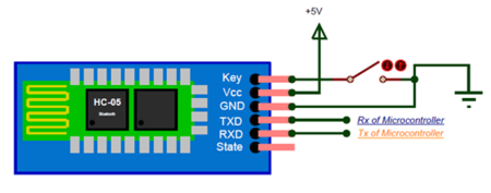
| HC05 | SJ2 Board |
|---|---|
| Vcc | 3.3 volts |
| Gnd | Gnd |
| Rx | GPIO4 Pin 28 |
| Tx | GPIO4 Pin 29 |
Software Design
Software Design Flow -
1) Initialize UART
2) Check the control signals in buffer and send appropriate CAN message
3) Send debug information to the application
Configure the GPIO pin functionality to UART using the gpio_construct_with_function API. Set the baud rate and the Queue size. The queue size should be set by calculating the periodic callback frequency and the speed at which data is being received and dequeued from the buffer. The baud rate of the UART set in SJ2 should be equal to the baud rate in HC05 board. The control signal data is continuously being received and stored in the UART queue created. Every 10hz (100ms), the data stored in the queue is removed and stored in the circular buffer. A valid data check is made and if valid data is present in the circular buffer, we check if any valid control signal is present in the buffer. The valid format for the GPS co-ordinate begins with the pattern ‘*GPS’ and ends with ‘#’. Once the GPS string is extracted successfully from the buffer, an API call is made to extract the correct latitude and longitude from the string. Similarly, all the other control signals have a valid format. Once a control signal is detected we extract the signal from the buffer, set a flag and send the respective CAN message to other boards. When the CAN message is sent it is important to erase that message from the buffer to avoid any unnecessary action in the next periodic callback. Using the sl_string library, the message was removed from the buffer and the rear index was adjusted based on the length of the signal. In the 10hz periodic callback function, debug information was also being sent in real-time to the android application. On the bridge and sensor board, all the CAN messages from other board were decoded. A list of all the debug information sent to the application is given below.
List of debug information sent to the android application –
 Ping Status
 Car Action
 Motor Speed
 Motor Speed PWM
 Ultrasonic left
 Ultrasonic right
 Ultrasonic back
 Ultrasonic front
 Geo compass current heading
 Geo compass destination heading
 Geo compass compass distance
 Driver Steer Speed
 Driver Steer Direction
 Headlight
 Test Button
 GPS Latitude
 GPS Longitude
 Battery Percentage
Technical Challenges
Creating Dynamic Buffer
From the android application the sensor board was receiving multiple control signals such as START, STOP, HON, HOFF, MTEST and GPS co-ordinates. The order in which these control signals were sent from the android application was not static. Hence it was necessary to create a dynamic circular buffer algorithm that will handle this scenario. Once a particular control signal was detected, the appropriate CAN message was sent and the signal was erased from the buffer to avoid unnecessary action in the next periodic callback. Changing the front index of the buffer once the signal was erased and moving other data present in the buffer was a difficult task. This was solved by getting the start index of the control message in the buffer, finding the size of the signal in bytes and overwriting that signal with other data present in the buffer from that particular start index using APIs from the sl_string library.
Bridge and Sensor Controller: Sensors
The sensor part of the bridge and sensor controller board is responsible for receiving the sensor readings, converting them to centimeters, and then sending them to the driver controller board over CAN. A total of four Maxbotix MaxSonar HRLV-EZ0 ultrasonic sensors are connected to the bridge and sensor controller; three in front and one in back.
We decided to use four ultrasonic sensors due to their relatively easy setup process, ranging capabilities, and reliability. We considered using lidar, but these sensors rely on additional factors such as lighting conditions. We specifically chose Maxbotix’s more expensive MaxSonar line because of their greater accuracy over their standard counterparts. The MaxSonar sensors have internal filtering to greatly reduce the amount of external noise affecting your sensor readings, making your readings far more reliable. The MaxSonar sensors also include an on-board temperature sensor to automatically adjust the speed of sound value based on the temperature of the environment the sensors are being used in. This means the sensor readings will stay consistent regardless of the weather and time of day (night time is much cooler than during the day).
Maxbotix offers ultrasonic sensors with different beam widths, and we chose their EZ0 sensors because they have the widest beam. Initially we thought this was a good idea because wider beams means an increased detection zone and less blind spots (width-wise). Please refer to the Technical Challenges section for details as to why we don’t recommend getting the widest possible beam for all four sensors.
Hardware Design
The ultrasonic sensors are powered using +5V, and connected to the SJtwo board’s ADC pins. There are only 3 available exclusively ADC pins on the SJtwo board, and so we changed the DAC pin to ADC mode in our ADC driver since we needed a total of 4 ADC pins. We left the RX pin of each sensor unconnected, and so each sensor ranges continuously and independently of one another. We don’t recommend doing this because the sensor beams interfere with each other when firing at the same time, but due to implementation issues, we weren’t able to use the RX pin approach. Please refer to the Technical Challenges section for details as to what problems we encountered when using the RX pin, and how we resolved the interference problems as a result of not using the RX pin.
Sensor Operating Voltage
The specific sensors we chose have an operating voltage requirement of +2.5V to +5.5V. Shown below from the MaxBotix datasheets is the detection pattern based on three different operating voltages. The detection zone decreases slightly as the operating voltage is decreased.
Additionally, the strength of the sound wave generated by the ultrasonic sensor decreases as the operating voltage decreases. A weaker sound wave means less sound “bouncing” back to the sensor, which can result in obstacles not getting detected, especially with softer surfaces like people and small plants, or thinner objects like railed gates or metal pipe handrails. We encountered this problem when using an operating voltage of 3.3V. Even though the distance the sensors could detect when powered with 3.3V was perfectly sufficient for our application, the sensors wouldn’t consistently detect softer and thinner obstacles (mainly people and thin pipes/rails). Choosing an operating voltage of 5V drastically improved the detection abilities of the sensors. The sensors consistently detected people, thin pipes sticking out of the ground, thin railed gates, metal pipe handrails, and plants that were at or above the mounting height of the sensors.
Sensor Mounts and Shields
In order to secure the sensors to the car chassis, we 3D printed sensor mounts for all four of the ultrasonic sensors. The sensor mounts are adjustable so that the nozzle of the sensor can be adjusted upward or downward. It was extremely helpful to have adjustable mounts because it took quite a bit of testing and trial and error to find the angle that the sensor nozzle needed to be tilted upward in order to detect correctly. If the sensor nozzle wasn’t pointed up high enough, the sensors would detect the road as an obstacle. We placed screws inside the mounting base hole to ensure the mount wouldn’t tilt out of position, and screwed the sensor into the mount to keep it from falling out or jiggling around. Shown below is the sensor mount design in CAD software.
Once 3D printed, the two pieces of the mount are fit together.
In addition to sensor mounts, we put adjustable sensor shields onto the car chassis in order to prevent beam interference between the left, right, and front sensors. When all sensors are firing, sometimes one of them would detect another sensor’s beam, resulting in a false reading. Adding shields greatly reduced the occurrence of a sensor detecting another sensor’s beam, and reduced the severity to which it affected the reading.
Unfortunately, due to the Coronavirus situation we did not have access to a 3D printer and were unable to print custom designed sensor shields (the sensor mounts were 3D printed before the Coronavirus shelter-in-place happened). To make shields, we cut rectangular pieces of cardboard (yellow cardboard for aesthetics) and hot glued them each to a popsicle stick. We drilled slits into some pvc pipe and placed the popsicle stick end of the shield inside. Screws were used to tighten down the popsicle stick and keep the shield in place. The pipe pieces were hot glued to plastic bottle caps, which were then screwed into the car chassis acrylic sheet. The shields can be adjusted left or right by twisting the bottle cap screwed to the acrylic sheet, and can be adjusted up or down by pushing up or pulling down on the popsicle stick end of the shield. The adjustable sensor shields and mounts on the car chassis are shown below.
Placement on Chassis
All four ultrasonic sensors were placed in their mounts, and then the bottom of the mount was hot glued to the acrylic sheet mounted on the car chassis. The placement of the sensors was an important decision to make because placing them too close together or not angling the left and right sensors outward enough resulted in beam interference.
A trial and error approach was taken to find the best sensor placement configuration for the left, right, and front sensors. The sensors were taped to the edge of a desk and the readings were observed to see if the values were stable or if the beams were interfering with each other. The testing setup used to determine the best sensor placement configuration can be seen below.
Through testing, it was determined that angling the left and right sensors outward at about 45 degrees, and placing them as far apart as possible on the acrylic sheet produced good results. The front and back sensors were centered on the acrylic sheet.
Software Design
The software design of the sensor modules consisted of the following ordered steps.
The flowchart below is for a single sensor between the initialization step, and the send CAN message step. The three in-between steps are done a total of four times (for each sensor). To keep things clean and easy to understand, the flowchart only shows the steps for a single sensor.
Initializing the Sensors
Some initialization and ADC driver modifications were required in order to get our sensors up and running. First, we wanted to use the analog out pin to receive data from all four sensors due to the simplicity of this interface. Since the Sjtwo board only has 3 available header pins with ADC functionality, we read the user manual for the LPC4058 [insert reference to user manual?] in order to see if any other available header pins had ADC capabilities. Shown below is Table 86 in the user manual, which lists all pins that have ADC functionality. Comparing this table with our SJtwo board, we found that ADC channel 3 located on P0[26] (labeled as DAC on SJtwo board) could be used as our fourth ADC pin.
We modified the existing ADC driver in order to add support for P0[26] as an ADC pin. An enumeration for ADC channel 3 was added to adc.h, and ADC channel 3 was added to the “channel check” if statement in adc.c’s adc__get_adc_value(...) function. These modifications are shown below.
In order to begin reading values from the sensors, all ADC pins must be set to “Analog Mode”. Looking at Table 85 in the LPC4058 user manual, we can see that upon reset, all ADC pins are in “Digital Mode”.
The SJtwo board’s ADC pins will not work if they are not set to “Analog Mode”, and so this code had to be added to the existing ADC driver since it was missing. We did the following IOCON register bit 7 clearing for all ADC pins inside the adc__initialize(...) function.
Once the modifications to the existing ADC driver had been made, we called adc__initialize(...) in our periodic_callbacks_initialize(...) function in order to perform the initialization of our ADC interface.
Converting to Centimeters
The raw ADC values read from each sensor aren’t inherently meaningful, and so they must be converted to centimeters in order to gauge the distance of obstacles. In order to perform the conversion, we sampled and recorded a sensor’s raw ADC values with obstacles placed at distances ranging from 0cm to 120cm in increments of 10cm. We decided to stop at 120cm because the process of collecting the sensor’s data was very time consuming and our maximum threshold value was 110cm, so there was no need to go farther. Shown below are the measurements gathered for our particular sensor model. It should be noted that the sensors produce a range of values when detecting an obstacle at a given distance, and so we averaged the values to obtain the most accurate results.
The values were plotted in a distance (Y-axis) versus ADC value (X-axis) graph, and a curve fit was performed in order to generate distance as a function of an ADC value. We used an application called Logger Pro because of its ability to automatically generate a curve fit for your data set.
We implemented the curve fit function generated by Logger Pro into code in order to convert our sensor’s ADC values to centimeters right after they were read from their respective ADC channel.
Filtering
Occasionally, the sensors will report incorrect values due to internal or external noise. Getting sensors that are more expensive usually decreases the number of times this happens, but even one incorrect reading can be a problem. For example, a sensor reading may incorrectly dip below the threshold and detect an obstacle even when there is none. Or worse, an obstacle may be within the threshold range but the sensor reading doesn’t reflect an obstacle being detected. Both of these scenarios can be avoided by filtering the sensor values before sending them to the driver controller over CAN.
The problem we were facing before filtering was the following; when setting up an obstacle in front of a sensor a certain distance away, 80cm for example, we monitored the sensor values to make sure all the readings were within a couple centimeters of 80cm. We noticed that occasionally, the output sensor readings would look something like “...80, 81, 80, 79, 82, 80, 45, 80, 78, 83, 81, 80, 79, 80…”. The sudden drop to 45 is clearly an incorrect reading because the obstacle remained at a constant 80cm away the entire time.
We considered several different filtering algorithms such as Mean, Median, Mode, and Kalman Filter. The Kalman Filter is very complex and so we didn’t feel the need to use it since other simpler options would work just as well for our application. The Mean Filter was completely out of the question because it averages the values. We want to remove the incorrect value, not incorporate it into the filtered value. The Median Filter requires the input values to be sorted in ascending order, which increases the run time and may cause us to run past our time slot in the 50Hz periodic callback function. Ultimately, we decided to use the Mode Filter because of its simplicity, short run time, and doesn’t require input values to be sorted. Choosing a filtering algorithm that has a short run time was one of the most important considerations because the sensors are running in a fast periodic callback function.
We implemented our own Mode Filter algorithm that took a number of input sensor values that have been converted to centimeters, finds the mode (most frequently occurring value) of the values, and then returns the mode as the filtered value. Through testing, we found that using an input size of 10 values to the mode filter was perfectly sufficient. A list of possible input values and the mode filter output can be seen below to better illustrate how our mode filter implementation works.
A corner-case that we needed to address was the possibility of multiple modes. This case can be seen in lines 2, 3, and 5 in the table above. We chose to return the mode that was most recent in order to reflect the most recent changes in sensor values. Take line 5 for example; all values occur exactly twice, which means there are five modes. The mode returned is 69 because it is the most recent mode.
As for the actual implementation of the Mode Filter, we based it off of the Counting Sort algorithm’s “bucket storing method” with some modifications in order to make the runtime O(n), with n being the input data size (10 in our case). There is no need to sort the values for our Mode Filter, and so the sorting part of the Counting Sort algorithm is completely omitted. The idea of storing the occurence of each value in an array element number equal to the current sensor value (in centimeters) is the only idea we used from the Counting Sort algorithm. An example of how our Mode Filter works can be seen below.
The size of the array inside the Mode Filter algorithm is specifically set to 600 elements. The array needs to have element numbers for every possible sensor value (in centimeters). Our sensor values range is from 0 to 500 centimeters and so we added an extra 100 just for safety, which gives us a total of 600 array elements. This is the reason we chose to convert our sensor values to centimeters before passing them as input into the Mode Filter. If we were to pass the raw sensor values into the filter, we would need an array with around 4096 elements (SJtwo board’s ADC is 12-bit, so 2^12 = 4096).
Technical Challenges
ADC
Three main problems occurred relating to our ADC interface. First, we were unable to get the sensors to output anything besides its maximum value. We checked the voltage on the ADC pin for multiple sensors and found that instead of increasing as an object got farther away, the voltage stayed constant. We concluded that since this was happening for all the sensors we tested, it must be a problem with our initialization code. After reading the ADC section in the user manual for our SJtwo board’s processor, we realized that our ADC driver was missing one thing. For each GPIO pin being used as an ADC pin, Pin 7 of the IOCON register has to be set to “ADC Mode”. After making this change, our sensors worked like a charm.
Next, we observed that our maximum sensor values weren’t the advertised 500cm. We experimented by putting obstacles in front of a sensor at varying distances and found that 300cm was the farthest the sensor could range. After reading the user manual for our SJtwo board’s processor, we realized that its ADC module operates in reference to 3.3V. We then switched to powering our sensors with 3.3V instead of 5V, hoping to get the 500cm range as advertised. This created the problem discussed below.
Our third problem we encountered was after making the switch from powering our sensors with 5V to 3.3V. 3.3V did not supply our sensors with enough power, and so we experienced large blind spots in our detection zone, and very inconsistent sensor readings due to the sensors generating weak sound waves from a lack of sufficient power. We decided to go back to powering our sensors with 5V since 300cm was more than enough ranging capability for this project.
Inconsistent Sensor Readings
When we first started testing the sensors, we used a single sensor to make sure our connections and code initialization was correct. We placed a flat object in front of the sensor at the same distance for a very long time to see how consistent our sensor readings were. We noticed that sometimes one reading would be very low or very high compared to the other readings. After doing some research, we found that this is a very common occurrence among sensors and can be resolved by filtering. We chose to implement our own filtering algorithm, which takes in a certain number of raw sensor values, finds the mode, and returns this as the filtered sensor value.
Slow Response to Obstacles
When we first began testing obstacle detection, we used one LED for each sensor for diagnostic testing purposes. If a sensor detected an obstacle, then its corresponding LED would turn on. When the obstacle was no longer present, the LED would turn off. We noticed that the response of the LED was very slow, and the sensor values in Busmaster would not change immediately when an obstacle was present. We solved this by moving our “get sensor values” code from 10Hz to 50Hz in order to get a faster obstacle detection response.
Additionally, when we started testing our PID acceleration, we noticed that the car would not stop in time before hitting an obstacle when moving at faster speeds. We monitored the sensor values on the android app to try and troubleshoot the issue. We found that the sensor values were not changing quick enough, and so the car was crashing because it didn’t have enough time to stop. We solved this problem by removing our “light up SJtwo board’s LEDs” function from our sensor’s CAN transmit function, which was slowing down the transmission of the sensor’s CAN messages.
Detecting Obstacles when None are Present
During our initial drive testing, our car would randomly take a sharp turn or stop when there were no obstacles in range. We hooked up Busmaster to the car’s on-board PCAN dongle and walked alongside the car while it was moving in order to diagnose the issue. We saw that the sensor values were dropping below the threshold when there were no obstacles present, and even when the car was not moving. This meant that the sensors were detecting the road or even parts of the car. We resolved this by tilting the sensor heads upwards until the sensor values were at their maximum (300cm for us).
Sensor's TX/RX Pins Not Working
Our first approach to solving sensor interference issues was to fire the sensor beams one at a time, and only after the previous sensor had finished. This functionality is built into MaxBotix sensors through the TX and RX pins. If these pins are connected by following the diagrams in the sensor user manual, a sensor will fire, and then trigger the next sensor to fire once it is finished. This process will repeat continuously or only once depending upon which wiring diagram you choose in the user manual.
We followed all coding guidelines and circuitry schematics in the user manual, but our sensors would fire once, and then go into a non-responsive idle state. After almost 2 weeks of trying different configurations, wiring, and coding implementations, we decided we couldn’t waste any more time on the TX/RX pin approach and opted to solve our interference problems in a different way.
Sensor Beam Interference
The beams of our three front sensors interfered with each other, resulting in completely inaccurate sensor readings. To solve this issue, we mounted the front sensor on a platform so that it stood about 4 inches higher than the left and right sensors. We also turned the left and right sensors 45 degrees outward and added shields in order to minimize the interference from the front sensor’s beam. We found that the optimal shield placement for our setup was turning them outwards at about 22.5 degrees or less from the sensor’s head.
Motor Controller
The Motor Controller SJ2-Board is mainly responsible for RC-Car’s steering and speed to move the car towards the destination. The RC-Car we are using is 2 Wheel Drive which means the front wheels are used for steering which is controlled by servo motor and the rear wheels are used for car’s forward and reverse movements which are controlled by DC Motor through ESC.
Hardware Design
ESC & DC Motor
The ESC(Electronic Speed Control, Traxxas ESC XL-05) and DC Motor we used were provided with the RC car. The DC motor is controlled by ESC using PWM signals provided by the motor controller for forward and reverse movements. We used the 7.4v LiPo battery to power up the ESC. The DC motor is powered by the ESC which has a dc-to-dc converter which converts 7.4v to 6v. ESC can provide high current to the power-hungry DC motor running at faster speeds. ESC has an LED and a button which is used for calibration and setting different modes for the car.
| Wires on ESC | Description | Wire Color |
|---|---|---|
| PWM(P2.1) | Takes PWM input from SJ2-Board | WHITE |
| VDD(6V) | Power Output | RED |
| GND | Ground | BLACK |
The car can be operated in the following 3 modes:
Sport mode(100% Forward, 100% Brakes, 100% Reverse)
Racing mode(100% Forward, 100% Brakes, No Reverse)
Training mode(50% Forward, 100% Brakes, 50% Reverse)
As we needed more than 50% speed for steep ramps, we used Sport mode. The frequency of the PWM signal fed to the servo motor is 100Hz. Based on the duty cycle set by the user, the car will go forward, reverse, or neutral. 10% - 20% duty cycle for reverse. 15% duty cycle for neutral. 15%-20% duty cycle for the forward motion.
Servo Motor
The servo motor we used is Traxxas 2075 which was provided with the car and it is responsible for steering the car. It takes the 6V power directly from ESC. The servo motor is controlled directly from the SJ2 micro-controller board. The PWM signal fed to the servo motor is of frequency 100Hz. Based on the duty cycle of the signal sent to the servo, it rotates in the left / right direction. 10% - 20% duty cycle for left. 15% duty cycle for straight. 15%-20% duty cycle for right.
| Wires on ESC | Description | Wire Color |
|---|---|---|
| PWM(P2.0) | Takes PWM input from SJ2-Board | WHITE |
| VDD(6V) | Power Input | RED |
| GND | Ground | BLACK |
RPM Sensor
There are two parts to the RPM sensor - one is the trigger magnet and the other is the sensor. The RPM sensor is used as an input to maintain a constant speed of the vehicle. The sensor mounts on the inside of the gear cover, the trigger magnet mounts on the DC motor shaft. The gear cover and motor shaft need to be removed using the toolkit provided along with the RC car. The procedure is similar to this video, but note that the car used in the video is a 4WD RC car by Traxxas. We made use of the trigger magnet attached to the spur gear to trigger a pulse on the sensor for every rotation of the spur gear. These pulses are then read by the SJ2 board to calculate rotations in a second and later convert it to RPM and MPH. The RPM sensor has 3 wires, the white wire is the output wire that provides the pulses to the SJ2 Board, and the other wires are Supply(6V) and GND. We also used a Pull Down 1K Resistor between Supply and RPM output wires.
| Wires on ESC | Description | Wire Color |
|---|---|---|
| GPIO(P0.6) | Provides pulses to Motor SJ2-Board | WHITE |
| VDD(6V) | Power Input | RED |
| GND | Ground | BLACK |
Software Design
Periodic Callbacks
Periodic Init: CAN, PWM(Servo and Motor), and Interrupts(RPM Sensor and Test button) were initialized in this function.
10Hz function: CAN messages were transmitted in this function. Also, cleared wheel interrupt rotations every 500ms.
100Hz function: Used this function to run at 20Hz. When the test button is pressed, Motor tests are performed else the car will follow driver commands.
Servo Motor
The PWM signal fed to the servo motor is of frequency 100Hz. The motor controller receives steer controls from the driver controller and it sends corresponding PWM value to the servo motor.
DC Motor
The PWM signal fed to the DC motor is of frequency 100Hz. The motor controller receives speed controls from the driver controller and it sends corresponding PWM value to the ESC which controls the DC motor.
RPM Sensor
RPM Sensor gives one pulse for each wheel rotation and the software calculates speed in mph using the no. of rotations. We are re-calculating the speed, every 500ms to maintain the speed of the motor while the car is going uphill or downhill.
Technical Challenges
Car Reverse Movement
Problem: The RC car sometimes wouldn’t go reverse and this used to happen randomly.
Solution: We checked the code and were giving the correct PWM values for the car to go reverse but the car wouldn’t do it sometimes. Then, we read the ESC manual and figured out that the wheels need to stop before giving the reverse command. For us, using these Commands (FULL REVERSE and STOP) before giving reverse PWM values for the reverse movement worked well. Also, we had to use current speed in combination with these FULL REVERSE commands to make sure that these reverse commands are given only when the car is moving forward.
Car Downhill Movement
Problem: The car would move too fast while downhill even though the feedback loop for the speed control is reducing the PWM.
Solution: The feedback loop to maintain the speed of the car was working fine while the car was going uphill, but while downhill the car would go too fast. To resolve this, we applied brakes(FULL REVERSE commands) to the car whenever the speed crosses a certain limit.
Mounting the RPM Sensor
Problem: We had a hard time figuring out where to mount the rpm sensor, as the documentation provided by Traxxas was for 4WD and ours was a 2WD RC car.
Solution: We figured out the place to mount the sensor by chance, using common sense. It was mounted on the inside of the gear cover, where a tiny hidden place was provided.
Geographical Controller
The geographical controller is responsible for providing the required destination heading angle(destination direction) and the destination distance using compass, GPS sensors for the car to reach destination. The GPS Module which we used was MTK3339 from adafruit this gave us the current GPS co-ordinates i.e. latitude and longitude, also we used the CMPS12 compass module for obtaining the current angle of the car and heading angle of the car. Geographical module is also responsible directing the car on the shortest path to the destination using waypoint algorithm(following the checkpoints) In our design, the shortest path finding and the continuous sending of different checkpoints as car reaches each of them is checked by the geographical module. The geographic controller is also responsible for obtaining the car’s current coordinates, computing distance and angle to the next checkpoint and send these results over the CAN bus to the Driver module. The Destination latitude and longitude were sent from the android application to the bridge and sensor module using bluetooth communication and transmitted to geographical module over CAN. Upon executing the Bucephalus Android mobile application, the user was able to select a destination location, by placing a marker on the Google Map fragment. The app parsed the destination's latitude and longitude coordinates and then sent them to the bridge controller. The pathfinding algorithm (Dikstra's algorithm) is used to calculate a path to the destination based on the starting location and a series of pre-defined checkpoints comprised of longitude and latitude data.
Hardware Design
GPS Module
As stated before, we used an Adafruit MTK3339 Ultimate GPS module. The GPS, along with the compass, was responsible for calculating bearing angle and distance from destination checkpoints. An external antenna was integrated, in order to help parse the GPS data more efficiently. The GPS module used UART, to communicate with the SJtwo board. The baud rate for the UART interface had to be initialized to 9600 bps also the UART two stop bits did not work and we had to change that to only one stop bit.
The GPS module came with a GPS lock, which allowed it to use satellite feedback to parse its location. This lock was indicated by an LED on the SJtwo board, which illuminated once the GPS Valid bit from NMEA string value is 1 or 2 . If no lock was found then the LED was not illuminated. The parsing of data from the GPS was in terms of NMEA sentences, each of which had a specific functionality. Out of the several NMEA sentences, $GPGGA was used. It provided essential information, such as latitude and longitude coordinates. The $GPGGA sentence is separated by commas, which the user had to parse in order to get useful data out of the module. We wrote a function to parse data from NMEA String recieved from the GPS module, with comma(,) as the delimiter.
The $GPGGA sentence looks like this: $GPGGA,230612.015,667.0013,N,12102.4634,W,2,04,5.7,508.3,M,,,,0000*13
The below table explains what each of the datum in the GPGGA sentence stands for:
The first 6 fields in the NMEA sentence are the most important ones. If field 4 said ‘N’, we checked the data in field 3 which had the latitude. Likewise, if field 6 said ‘W’, we check the data in field 5 which contained the longitude. It is important to note that the longitude and latitude data are in the form degree-minute-seconds instead of true decimal. If not properly converted, they could have offset the location readings by miles.
Compass Module
The CMPS12 is tilt compensated compass. Employing a 3-axis magnetometer, a 3-axis gyro and a 3-axis accelerometer. At the core of the module is the superb BNO055 running algorithms to remove the errors caused by tilting of the PCB. Power supply requirements are flexible, you can feed between 3.3 - 5v and the module draws a nominal 18mA of current. A choice of serial or I2C interfaces can be used for communication.
Overview of outputs Heading, 16 bit: 2 outputs, one calculated by Bosch and one by us Heading, 8 bit: 0-255 scaled for simpler requirements Pitch: +/- 0-90° or +/- 0-180° Roll: +/- 0-90° Raw sensor outputs: 3 x 16 bit integers for each of the Magnetometer, accelerometer and gyro
Read Compass Heading
Compass heading is read by initiating the I2C read operation, and by passing the compass address (0xC0) and the register address (0x2). These values, along with the temporary array must be passed in a single I2C read operation. An example of the code snippet is as below:
void compass__read_current_gps_coordinate() {
 gps__run_once();
 gps_coordinates_t current = gps__get_coordinates();
 current_gps_coordinates.BRIDGE_GPS_latitude = current.latitude;
 current_gps_coordinates.BRIDGE_GPS_longitude = current.longitude;
}
static float compass__read_angle_from_i2c_cmps12(void) {
 uint16_t value;
 i2c__read_slave_data(I2C__2, COMPASS_ADDRESS, SLAVE_READ_ANGLE, READ_ANGLE_DATA, 2);
 value = READ_ANGLE_DATA[1];
 value |= READ_ANGLE_DATA[0] << 8;
 float f_value = (float)value / 10.0f;
 return f_value;
}
Check Compass Calibration
The calibration level is checked to see how well the compass is calibrated. The 8-bit value resides in register 0x1E according to the diagram below:
When each of the 2-bit calibration value is 0, this means the specific field is not calibrated, a value of 3 means the field is fully calibrated. This is done by performing an I2C read operation, whilst reading the 0xC0 and the 0x1E registers, to determine if it’s calibrated or not. The code snippet looks as below:
bool check_calibration_level(uint8_t* result) {
 char calibration_state_address = 0x1E;  // register 30
 bool is_calibration_successful = false;
 if (read_byte_from_i2c_device(COMPASS_ADDRESS, calibration_state_address, 1, result)) {
   is_calibration_successful = true;
 }
 return is_calibration_successful;
 }
Essential GPS Data Calculation
Bearing, Distance, and Deflection Angle Calculation
Bearing, calculated as an angle from true north, is the direction of the checkpoint from where the car is, it is calculated using current and destination GPS coordinates . The code snippet to calculate bearing is below. lon_difference is the longitude difference between checkpoint and current location. GPS is the current location, and l_destination_gps_coordinates is checkpoint location. For all trig functions used below, the longitude and latitude values have to be converted to radian. After the operations, the final bearing angle is converted to degrees and a positive value between 0 and 360.
 if (check_valid_source_destination_coordinates(&l_current_gps_coordinates, &l_destination_gps_coordinates)) {
   convert_source_destination_to_radian(&l_current_gps_coordinates, &l_destination_gps_coordinates);
   lon_difference =
       (l_current_gps_coordinates.BRIDGE_GPS_longitude - (l_destination_gps_coordinates.BRIDGE_GPS_longitude));
   bearing = atan2(
       (sin(lon_difference) * cos(l_destination_gps_coordinates.BRIDGE_GPS_latitude)),
       ((cos(l_current_gps_coordinates.BRIDGE_GPS_latitude) * sin(l_destination_gps_coordinates.BRIDGE_GPS_latitude)) -
        (sin(l_current_gps_coordinates.BRIDGE_GPS_latitude) * cos(l_destination_gps_coordinates.BRIDGE_GPS_latitude) *
         cos(lon_difference))));
   bearing = fmodf(((bearing * 180) / PI) + 360, 360);
   }
 bearing = round_upto_2_decimal(bearing);
 return bearing;
Distance between the car and the checkpoint can be calculated using GPS current and gps coordinate. The code snippet to calculate distance is shown below. It utilizes the haversine formula to calculate the great-circle distance between two points on a sphere given their longitudes and latitudes. Like the bearing calculation, all coordinates must be in radian. The value 6371 below is earth’s radius in km.
if (check_valid_source_destination_coordinates(&l_current_gps_coordinates, &l_destination_gps_coordinates)) {
   convert_source_destination_to_radian(&l_current_gps_coordinates, &l_destination_gps_coordinates);
   float lat_diff = l_destination_gps_coordinates.BRIDGE_GPS_latitude - l_current_gps_coordinates.BRIDGE_GPS_latitude;
   float lon_diff =
       l_destination_gps_coordinates.BRIDGE_GPS_longitude - l_current_gps_coordinates.BRIDGE_GPS_longitude;
   float a = pow(sin(lat_diff / 2), 2) + cos(l_current_gps_coordinates.BRIDGE_GPS_latitude) *
                                             cos(l_destination_gps_coordinates.BRIDGE_GPS_latitude) *
                                             pow(sin(lon_diff / 2), 2);
   float c = 2 * atan2(sqrt(a), sqrt(1 - a));
   distance = 6371 * 1000 * c;
After obtaining heading and bearing values, deflection angle, the difference in angle between your car and the checkpoint, is calculated. This is the angle value that is given to the master for steering purposes. These values are given to the driver module for taking the decision of the car direction
deflection = heading_angle->GEO_COMPASS_current_heading - heading_angle->GEO_COMPASS_desitination_heading;
 if (deflection > 180) {
   deflection -= 360;
 } else if (deflection < -180) {
   deflection += 360;
 }
Software Design
The complete flowchart for the geo module is shown below. We broke all the tasks in two iterations of the 10Hz function because if we do them in one iteration, we get the task overrun error. Therefore, the gps update rate is 5Hz.
Technical Challenges
1. Calibrating Compass Module
The compass module was not giving stable values on default calibration. The compass north changed every time the module powered off. The compass value would change after a full 360-degree rotation. The compass value moved up on tilting the module.
Solution:
Step 1: Keep the compass stable on the ground to calibrate the gyro sensor. Step 2: Now, randomly move the module to calibrate the magnetometer by rotating the car in all possible directions. Step 3: After this, tilt the compass module in all directions and slowly move the module 360-degrees clockwise and anti-clockwise to calibrate the accelerometer. Step 4: check the debug values of compass angle and measure the angle with phone
2 Inaccurate GPS Coordinates
The GPS module took a lot of time to get a fix and after it got a fix, the values were not accurate because of which the car was going at naccseible directions.
Solution:
We used the GPS antenna to get a faster fix and we noticed a lot more accurate GPS coordinates after connecting the antenna.
3 Unreliable GPS lock
After the GPS module got a lock, it would sometimes lose the lock and give incorrect GPS coordinates as the GPS Valid bit value sometimes came as 1 or 2.
Solution:
To fix this issue, we checked the GPS lock status and sent pre-determined error value to the master so that the master knows the GPS module is giving incorrect values and take decision accordingly. Also used a dedicated onboard LED to indicate GPS fix.
Driver Module
The Driver module is the brain of our autonomous car. It takes input from the Sensor and Geological controller to compute the direction of travel and sends the driving signal to the motor controller. It communicates with other modules via the CAN bus using CAN transceiver.
Hardware Design
Software Design
- The Driver control module is the brain of the Self-driving car as it takes all the critical driving decisions based on messages from the other control modules like Sensor, Geo and sends the message to the Motor control module for driving the car.
- The Driver Board receives CAN message from Geological board which includes the current heading angle of the car, destination heading angle of the car, and distance to the destination.
- The Driver Board also receives CAN message from the sensor board which includes the sensor values indicating if an obstacle is present or not. If obstacle is present the distance to the obstacle is part of the message. The values for front, left, right and back sensor is included in the message.
- The driver control board makes use of the message from the geological board and sensor board to compute the motor command for driving the car.
- The driver board has two algorithms, one which computes the motor commands based on geo controller information and other which computes the direction based on obstacle avoidance algorithm. The Obstacle avoidance algorithm has higher priority and is used if there is an obstacle detected by any of the sonar sensors. Otherwise, it makes use of the geo algorithm to compute the motor commands.
- The geo algorithm computes the deflection angle based on current and destination heading and decides on the directions of the car. The distance to the destination decides the forward movement of the car.
static float driving_algo__compute_deflection(const dbc_GEO_COMPASS_s *heading_angle) {
float deflection = heading_angle->GEO_COMPASS_desitination_heading - heading_angle->GEO_COMPASS_current_heading;
if (deflection > 180) {
deflection -= 360;
} else if (deflection < -180) {
deflection += 360;
}
return deflection;
}
static void driving_algo__get_gps_heading_direction(dbc_DRIVER_STEER_SPEED_s *driving_direction) {
float deflection = driving_algo__compute_deflection(¤t_and_destination_heading_angle);
driving_direction->DRIVER_STEER_move_speed = DRIVER_STEER_move_FORWARD_at_SPEED;
if (deflection > TOLERANCE_DIRECTION_POSITIVE) {
driving_direction->DRIVER_STEER_direction =
(deflection < 45) ? DRIVER_STEER_direction_SOFT_RIGHT : DRIVER_STEER_direction_HARD_RIGHT;
} else if (deflection < TOLERANCE_DIRECTION_NEGATIVE) {
driving_direction->DRIVER_STEER_direction =
(deflection > -45) ? DRIVER_STEER_direction_SOFT_LEFT : DRIVER_STEER_direction_HARD_LEFT;
} else {
driving_direction->DRIVER_STEER_direction = DRIVER_STEER_direction_STRAIGHT;
}
}- The obstacle avoidance algorithm first fills the data structure which maintains information if the obstacle is far, near, or very near. The algorithm then uses this information to compute direction to drive the car away from the obstacle.
typedef union {
  struct obs {
    uint8_t front : 2;
    uint8_t back : 2;
    uint8_t right : 2;
    uint8_t left : 2;
  } obs;
  uint8_t obstacle_var;
} obstacle_s;- The Navigation and Obstacle avoidance algorithms run @20Hz, CAN messages are processed @20Hz, and debug information is sent out @1Hz.
The detailed flowcharts are shown below.
Technical Challenges
- Car Not Detecting Obstacle Fast Enough
Problem Summary: In spite of having a decent preliminary obstacle avoidance logic, the car would not stop/steer away from obstacles rather chared onto them.
Solution: After multiple testing, we observed that the speed of the car was too high for it to lose all of its momenta and come to a standstill. So we started running the car at a slower speed. Also, we added brake functionality to quickly stop the car if an obstacle is detected very near
Additonally we adjusted the threshold by calculating the distance car can travel based on time required to read the obstacle data and time required for car to take action based on the obstacle.
- Multiple decisions needed to be taken
Problem Summary: On the onset of each and every module, we had to always fine-tune our master logic so that it incorporated all the signals and make the system work in equilibrium. We had to incorporate start command, GPS and sensor directions which added to the decision making logic.
Solution: A robust state machine helped us to build a logically correct algorithm to incorporate every module in our system to work in order and in harmony.
Mobile Application
Gitlab Link <https://gitlab.com/bucephalus/bucephalus-android-app>
Software Design
The Android Application evolved as we added one module per week as the course progressed. I started with understanding the Google Maps and how to use it in an Application, later on developed bluetooth code and finally introduced the state machine to selectively disable certain functions as to handle the bugs on a button being pressed when it was not supposed to be pressed. The implementation of the Android App was completed in a single Activity, we just had another Activity for the splash screen to display the logo.
We developed 9 revisions of the application until we arrived at the final App used for the demo.
The flowchart of the state machine used for the UI is as below-
User Interface
We kept the user interface as minimal as possible, with an extra feature of turning ON/OFF the headlights of the car. The UI had few TextFields, Google Maps and Buttons. In order to decrease minimise the use of Buttons, I decided to use the same button for Set Destination and Start by using a State Machine to change the functionality of Button.
startNdestinationButton.setOnClickListener(new View.OnClickListener() {

    @Override
    public void onClick(View v) {

        //START BUTTON
        if(current_state_of_car == State.destination_sent || current_state_of_car == State.car_stopped){

            try {
                BtSocket.getOutputStream().write(tobesent_start.getBytes());
            } catch (Exception e) {
                Toast.makeText(MapsActivity.this, "is HC-05 turned on?", Toast.LENGTH_SHORT).show();
                bt_failed = true;
            }

            if (bt_failed == false) {
                infoText.setText(" sent data - " + tobesent_start);
                started = true;
                current_state_of_car = State.car_started;
            } else {
                infoText.setText(" sending data failed");
            }

        }
        //DESTINATION BUTTON
        else if(current_state_of_car == State.dest_selected){

            try {
                if (destination_selected == true) {
                    BtSocket.getOutputStream().write(tobesent_destination.getBytes());
                } else {
                    Toast.makeText(MapsActivity.this, "select destination on map", Toast.LENGTH_SHORT).show();
                    bt_failed = true;
                }
            } catch (Exception e) {
                Toast.makeText(MapsActivity.this, "is HC-05 turned on?", Toast.LENGTH_SHORT).show();
                bt_failed = true;
            }

            if (bt_failed == false) {
                infoText.setText(" sent destination - " + tobesent_destination);
                current_state_of_car = State.destination_sent;
            } else {

            }
        }
    }
});

Timr = new CountDownTimer(30000, 500) {
    @Override
    public void onTick(long millisUntilFinished) {

        if(current_state_of_car == State.app_started){

            infoText.setText(" 0 - connect to bucephalus ..");
            startNdestinationButton.setText("SET DESTINATION");
            connecttocarButton.getBackground().setColorFilter(getResources().getColor(holo_red_light), PorterDuff.Mode.MULTIPLY);

        }else if(current_state_of_car == State.connected_to_car){

            infoText.setText(" 1 - mark destination on the map");
            connecttocarButton.getBackground().setColorFilter(getResources().getColor(holo_blue_light), PorterDuff.Mode.MULTIPLY);

        }else if(current_state_of_car == State.dest_selected){

            infoText.setText(" 2 - set destination to send it to car");

        }else if(current_state_of_car == State.destination_sent){

            infoText.setText(" 3 - start the car");
            destinationText.setText(" heading to " + tobesent_destination);
            startNdestinationButton.setText("START");

        } else if(current_state_of_car == State.car_started){

            infoText.setText(" 4 - stop button is active ..");

        }else if(current_state_of_car == State.car_stopped){

            infoText.setText(" 5 - car is stopped");

        }

    }

    @Override
    public void onFinish() {
        start();
    }
}.start();
Bluetooth
Initially we thought of using Wi-Fi for our project, but later on choose Bluetooth as suggested by the ISA team. The mobile to ecu communication is simple, but it gets complicated with ecu to mobile communication as the UI has to be updating with the latest data and the receive function should run as a Thread. We did face few challenges over here as the App would crash, it took a few trials until we arrived at the right code.
BtAdapter = BluetoothAdapter.getDefaultAdapter();

if (!BtAdapter.isEnabled()) {
    BtAdapter.enable();
}

BtAdapter.startDiscovery();

/*

BondedDevicesSet = BtAdapter.getBondedDevices();

ArrayAdapter<String> arrayAdapter = new ArrayAdapter<String>(this, android.R.layout.simple_list_item_1, arrayListNameAddress);

for (BluetoothDevice bt : BondedDevicesSet) {
    //this array is used for debuggin purpose and also to let the user know which device the start is sent
    arrayListNameAddress.add(bt.getName() + "\n" + bt.getAddress() + "\n");

    //this array has only the address to be used for connecting later on
    arrayListAddress.add(bt.getAddress());
}

listview.setAdapter(arrayAdapter);

listview.setOnItemClickListener(new AdapterView.OnItemClickListener() {
    @Override
    public void onItemClick(AdapterView<?> parent, View view, int position, long id) {
        BtServerAddress = arrayListAddress.get(position);
        BtServerNameAddress = arrayListNameAddress.get(position);
        BluetoothDevice Btdevice = BtAdapter.getRemoteDevice(BtServerAddress);
        try{
            BtSocket = Btdevice.createRfcommSocketToServiceRecord(UUID.fromString(SERVICE_ID));
            BtSocket.connect();
        }catch (Exception e){
            //Toast.makeText(MapsActivity.this, e.getMessage().toString(), Toast.LENGTH_SHORT).show();
            Toast.makeText(MapsActivity.this, "is HC-05 turned on?", Toast.LENGTH_SHORT).show();
            bt_failed = true;
            try {
                BtSocket.close();
            } catch (IOException ex) {
                ex.printStackTrace();
            }
        }

        if(bt_failed == false){
            displayText.setText(" connected to - " + BtServerNameAddress + "\n");
            ecutomobile thread_ecutomobile = new ecutomobile();
            thread_ecutomobile.start();
        }
    }
}
);

class ecutomobile extends Thread {

    public void run() {
        // Keep looping to listen for received messages
        while (true) {

            if(run_thread == true){

                try {
                    int bytes;
                    byte[] buffer = new byte[256];
                    ByteArrayInputStream input = new ByteArrayInputStream(buffer);
                    inputStream = BtSocket.getInputStream();
                    bytes = inputStream.read(buffer);            //read bytes from input buffer
                    String readMessage = new String(buffer, 0, bytes);
                    // Send the obtained bytes to the UI Activity via handler
                    handler.obtainMessage(handlerState, bytes, -1, readMessage).sendToTarget();
                } catch (Exception e) {
                    Log.getStackTraceString(e);
                }

            }else{

                try {
                    sleep(100);
                } catch (InterruptedException e) {
                    e.printStackTrace();
                }

            }

        }
    }
}


handler = new Handler(Looper.getMainLooper()) {

    @Override
    public void handleMessage(@NonNull Message msg) {

        super.handleMessage(msg);

        String speed = null, pwm = null, ch = null, dh = null, cd = null;
        int state = 0;
        if (msg.what == handlerState) {                                     //if message is what we want
            String readMessage = (String) msg.obj;                          // msg.arg1 = bytes from connect thread
            recDataString.append(readMessage);                              //keep appending to string until ~
            int endOfLineIndex = recDataString.indexOf("#");

            if (endOfLineIndex > 0) {                                       // make sure there data before ~
                String dataInPrint = recDataString.substring(0, endOfLineIndex);
                try {
                    String tokens[] = dataInPrint.split("\\s*,\\s*");
                    displayText.setText(" CH = " + tokens[7] + "\n" + " DH = " + tokens[8] + "\n" + " CD = " + tokens[9] + "\n");
                } catch (Exception e) {
                    Toast.makeText(MapsActivity.this, e.getMessage().toString(), Toast.LENGTH_SHORT).show();
                }
                recDataString.delete(0, endOfLineIndex);
                dataInPrint = " ";
                recDataString.setLength(0);         //MOOOOSSSSTTTTT IMPORTANT - spend entire night and including this made it work!
            }
        }
    }
};
Google Maps
The Google Map SDK is really huge with a lot of features, to get started we had to create an account on Google Cloud Console and enable the API and later use the API key on the Android App inside the Manifest file. One issue we faced with sending the Lat Long coordinates to the ecu was that Google Maps provides a high resolution coordinate with 10 digits after decimal points, so we trimmed it to 6 digits and we did not notice any comparable difference in the functionality of the car.
mFusedLocationProviderClient = LocationServices.getFusedLocationProviderClient(this);
mapFragment.getMapAsync(this);

if(ActivityCompat.checkSelfPermission(this, Manifest.permission.ACCESS_FINE_LOCATION) == PackageManager.PERMISSION_GRANTED){
    getCurrentLocation();
}else{
    ActivityCompat.requestPermissions(MapsActivity.this, new String[]{Manifest.permission.ACCESS_FINE_LOCATION}, 44);
}

@Override
public void onMapReady(GoogleMap googleMap) {

    mMap = googleMap;

    mMap.setOnMapClickListener(new GoogleMap.OnMapClickListener() {
        @Override
        public void onMapClick(LatLng latLng) {

            int precision = (int) Math.pow(10,6);

            double new_latitude = (double)((int)(precision*latLng.latitude))/precision;
            double new_longitude = (double)((int)(precision*latLng.longitude))/precision;

            LatLng myloc = new LatLng(latLng.latitude, latLng.longitude);
            mMap.addMarker(new MarkerOptions().position(myloc).title("Destination"));
            mMap.moveCamera(CameraUpdateFactory.newLatLng(myloc));

            tobesent_destination = "GPS" + new_latitude + "," + new_longitude +"#";
            destination_selected = true;
            current_state_of_car = State.dest_selected;
        }
    });
}

private void getCurrentLocation() {

    try{
        Task<Location> task = mFusedLocationProviderClient.getLastLocation();
        task.addOnSuccessListener(new OnSuccessListener<Location>() {
            @Override
            public void onSuccess(final Location location) {
                mapFragment.getMapAsync(new OnMapReadyCallback() {
                    @Override
                    public void onMapReady(GoogleMap googleMap) {
                        LatLng currentLocation = new LatLng(location.getLatitude(), location.getLongitude());

                        MarkerOptions options = new MarkerOptions().position(currentLocation).title("bucephalus");
                        mMap.animateCamera(CameraUpdateFactory.newLatLngZoom(currentLocation, 17));
                        mMap.addMarker(options);
                    }
                });
            }
        });

    }catch(Exception e){

    }
}

@Override
public void onRequestPermissionsResult(int requestCode, @NonNull String[] permissions, @NonNull int[] grantResults) {
    super.onRequestPermissionsResult(requestCode, permissions, grantResults);

    mLocationPermissionGranted = false;
    switch (requestCode) {
        case 44: {
            // If request is cancelled, the result arrays are empty.
            if (grantResults.length > 0
                    && grantResults[0] == PackageManager.PERMISSION_GRANTED) {
                mLocationPermissionGranted = true;
                getCurrentLocation();
            }
        }
    }
}
Technical Challenges
App Crash
We faced a few issues with the Android App as it used to crash, using better modules (Handler, Threads) solved the issue.
UI Crash
The UI was crashing/hanging because proper data received continuously from bluetooth had to be updated on the UI. Android provides Handler modules using which the issue was solved.
Bluetooth Code
Developing the bluetooth code was a challenge as communication from ecu to mobile and mobile to ecu had to be developed. We used a Thread to develop the code, I would suggest future students develop Bluetooth code as a Service as this will help with accessing bluetooth over multiple screens and this would help in making a good UI for Debug values.
Conclusion
This project taught us how to work with so many people with same goal but different working patterns to come together and execute their ideas together in tandem to accomplish the team goal. We developed an autonomously navigating RC car. Each team member brought unique skills, passions and personalities to the project. Some team people were skilled with designing and placing components on the PCB Board, while others were skilled in firmware development, project management, catching bugs, organizing meetings etc. Some people had the ability to lighten the mood on disappointing demo days, while others had the management skill to keep the team focused and making the car its best version than the day before, while avoiding burning the team out at each other. When these different minds and their skills came together, it resulted in the final product that we all are extremely proud of, as well as one that performed well on the final demo day. The shelter in place due to COVID-19 brought more challenges in coordination as we couldn't meet much for in person meetings and everyone needed the hardware for testing their code. It was difficult for a single person who had all the hardware to always test with few members or alone and to explain to others where exactly their code was failing.
It wasn't always fun and lively though. We experienced soaring highs, during few of our progress demos, where we hit almost all of our specs. We also experienced devastating lows, when we were not able to demo properly as there were coordination issues offline at the start. While we look back fondly on our project, the reality is that it was the result of 7 graduate students spending almost every day of the semester developing and fine tuning the final product. We failed and succeeded together as a team. The goal was too important. Blame fell on the team as a whole and so did success and praise. We succeeded because we failed together. We succeeded because we didn't let failure break us and instead worked harder to fine tune and improve our test cases so that no case in the testing is left unexplored and the car worked exceptionally well.
There was so much to learn. Always something new, it felt like. We developed a clean and best working PCB, to integrate all of our subsystems together with least number of wires needed and visible on the car, even though none of us had experience developing a board that complex before. We also approached new challenges such as developing an Android Mobile Application, even though none of us knew JAVA or knew Android Studio beforehand. We never stopped learning. We learned the value of investing in quality components. We honed our unit testing skills, trying to write firmware that was as high quality as our hardware. We learned about CANbus on an intimate level and applied all of the knowledge. Testing at residential area gave us a tough time especially with the GPS module and the ultrasonic sensors as the google maps did not give us the exact co-ordinates of internal society roads, and the ultrasonic sensors faced difficulties in detecting low height sidewalks.
Working on this project was a difficult yet ultimately rewarding experience. It taught us how to make use of unit tests so that we don't need hardware at all and this helped alot in online coordination with team members. We can't stress enough how important is to start the project as early as possible in the semester and to keep pushing until the final demo. Each of contributed roughly 20 hours a week to work on the project. As a result, we were exhausted by the end of it, but we also never had to pull nights sometimes to meet the deadlines. We had excellent leadership from our team lead, Mohit Ingale, as well as our mentors, Preet and ISA members Aakash, Vignesh. We also had excellent peers in CMPE 243 and are proud of what they achieved as well. Overall, we were happy to be part of this class and we hope that our project will inspire future students to develop electric vehicles.
Project Video
Project Source Code
Project Source Code Android Application Code
Advice for Future Students
- FORM YOUR TEAM AS EARLY AS POSSIBLE AND START WORKING ON THE PROJECT AS EARLY AS POSSIBLE Don't go by the team size. There is lot of work which keeps on stalking up and then can haunt us in the end semester.
- If you are having trouble with your GPS, compass, or ultrasonic sensors (due to more obstacles at residential areas) try testing on top of one of the SJSU parking garages on a weekend. There is much less signal interference.
- Order spare parts and all parts before hand so that you don't keep running around at last moment. You will encounter defective parts and shipping wastes time and increases stress (especially nearing demo day)
- Make sure to get a power supply that doesn't burn your board's fuse and supplies current more than 1A. When all the car's subsystems are running, the current draw may be higher than expected
- Don't go for cheap modules and car model from Ebay, those will probably waste more of your time and probably cost you more at the end as you might end up buying hardware again. Get quality modules and they will pay for themselves down the road.
- Make use of all the holidays specially Spring break as there are assignments from other classes too and this would be the best time when probably everyone can be free. This will save you on the final DEMO day.
- Getting access to a 3D printer can be very useful for this project, with which you can customize sensor mounts, car hood.
- Take advantage of the code reviews that Preet offers! They will fix a lot of bugs in your code and will make it a lot easier to manage each module.
- We scored the highest marks in each assignment. We feel it was because we synced up every week, we had 11 Meetings in total and 7 Workdays. We had a meeting every Wednesday to discuss the assignment and had an assigned workday on Saturday to work on the assignment. This led to smooth workflow avoiding hassles and also helped us put in more time on the assignment.
