Difference between revisions of "S14: CAN Firmware Uploader"
Proj user3 (talk | contribs) (→Design & Implementation) |
(→Project Source Code) |
||
| (89 intermediate revisions by one other user not shown) | |||
| Line 1: | Line 1: | ||
| − | |||
| − | |||
| − | |||
| − | |||
| − | |||
| − | |||
| − | |||
| − | |||
| − | |||
| − | |||
| − | |||
| − | |||
== Project Title == | == Project Title == | ||
| + | CAN Firmware Uploader | ||
== Abstract == | == Abstract == | ||
| − | + | Designing a method to load firmware through CAN bus. Master device will be able to load firmware in a slave device. | |
== Objectives & Introduction == | == Objectives & Introduction == | ||
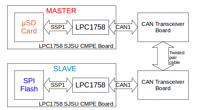
| − | + | The main objective of this project is to design a CAN boot loader protocol. The firmware will be stored in .bin format in the SD card and this card will be connected to master device. This bin file will be transferred from master device to slave device through CAN bus. The receiver board flashes this received bin file into internal flash from external flash using IAP once this file transfer process is completed and restarts to start executing from this newly flashed bin file. | |
| + | |||
| + | Block Diagram: | ||
| + | |||
| + | [[File:CmpeE244_S14_T7_blockDiagramSystem.png]] | ||
=== Team Members & Responsibilities === | === Team Members & Responsibilities === | ||
| Line 53: | Line 46: | ||
| 3/14 | | 3/14 | ||
| Build H/w and read on establishing CAN communication | | Build H/w and read on establishing CAN communication | ||
| − | | | + | | Completed.Hardware built. Plan to test it with CAN driver by 3/22 |
|- | |- | ||
! scope="row"| 4 | ! scope="row"| 4 | ||
| Line 59: | Line 52: | ||
| 3/21 | | 3/21 | ||
| Design CAN protocol and Establish SIMPLE CAN communication | | Design CAN protocol and Establish SIMPLE CAN communication | ||
| − | | | + | | Completed on 4/17. We faced few problems in CAN driver and hardware. |
|- | |- | ||
! scope="row"| 5 | ! scope="row"| 5 | ||
| Line 65: | Line 58: | ||
| 3/28 | | 3/28 | ||
| Read/Develop about SPI Flash driver to read and write .bin files | | Read/Develop about SPI Flash driver to read and write .bin files | ||
| − | | | + | | Completed on 4/21. Integrating bin reading logic with CAN driver. |
|- | |- | ||
! scope="row"| 6 | ! scope="row"| 6 | ||
| Line 71: | Line 64: | ||
| 4/11 | | 4/11 | ||
| Transmit .bin file by integrating SPI driver and CAN | | Transmit .bin file by integrating SPI driver and CAN | ||
| − | | | + | | Ongoing. Tried sending sample bin to the receiver board. File save logic at receiver is being implemented now. As of now facing few sync problems in CAN ISR. Completed on 5/1/2014. |
|- | |- | ||
! scope="row"| 7 | ! scope="row"| 7 | ||
| Line 77: | Line 70: | ||
| 4/18 | | 4/18 | ||
| Read about IAP | | Read about IAP | ||
| − | | | + | | Completed on 4/22 |
|- | |- | ||
! scope="row"| 8 | ! scope="row"| 8 | ||
| Line 83: | Line 76: | ||
| 4/25 | | 4/25 | ||
| Implement IAP | | Implement IAP | ||
| − | | | + | | Completed on 4/22. It has to be integrated with CAN transfer state diagram logic. |
|- | |- | ||
! scope="row"| 9 | ! scope="row"| 9 | ||
| Line 89: | Line 82: | ||
| 5/5 | | 5/5 | ||
| Testing and remove bugs, further enhancements | | Testing and remove bugs, further enhancements | ||
| − | | | + | | Ongoing. Completed testing on 5/1/2014. Further enhancements could not be done due to time constraints. |
|- | |- | ||
! scope="row"| 10 | ! scope="row"| 10 | ||
| Line 95: | Line 88: | ||
| 5/8 | | 5/8 | ||
| Demo | | Demo | ||
| + | | Demo is on 5/22/2014. Wiki page update going on. Demo will be given at 5/22/2014 6pm and Wiki page updation will be completed by 6pm. | ||
| | | | ||
|} | |} | ||
| Line 100: | Line 94: | ||
== Parts List & Cost == | == Parts List & Cost == | ||
<table class="wikitable"> | <table class="wikitable"> | ||
| − | <th>Parts</th> <th>Cost*</th> | + | <th>Parts</th> <th>Quantity</th> <th>Rate</th> <th>Cost*</th> |
<tr> | <tr> | ||
| Line 108: | Line 102: | ||
<td> | <td> | ||
| − | $80.00 | + | 2 |
| + | </td> | ||
| + | |||
| + | <td> | ||
| + | $80 | ||
| + | </td> | ||
| + | |||
| + | <td> | ||
| + | $160.00 | ||
</td> | </td> | ||
</tr> | </tr> | ||
| Line 118: | Line 120: | ||
<td> | <td> | ||
| − | $1.02 x2 | + | 2 |
| + | </td> | ||
| + | |||
| + | <td> | ||
| + | $1.02 | ||
| + | </td> | ||
| + | |||
| + | <td> | ||
| + | $2.04 | ||
| + | </td> | ||
| + | </tr> | ||
| + | |||
| + | <tr> | ||
| + | |||
| + | <td> | ||
| + | Resistors(1K x2,120E x2) | ||
| + | </td> | ||
| + | |||
| + | <td> | ||
| + | 4 | ||
| + | </td> | ||
| + | |||
| + | <td> | ||
| + | - | ||
| + | </td> | ||
| + | |||
| + | <td> | ||
| + | $1.00 | ||
</td> | </td> | ||
</tr> | </tr> | ||
| Line 124: | Line 153: | ||
<tr> | <tr> | ||
<td> | <td> | ||
| − | + | Capacitors (1nF x2) | |
| + | </td> | ||
| + | |||
| + | <td> | ||
| + | 2 | ||
| + | </td> | ||
| + | |||
| + | <td> | ||
| + | - | ||
| + | </td> | ||
| + | |||
| + | <td> | ||
| + | $1.00 | ||
| + | </td> | ||
| + | </tr> | ||
| + | |||
| + | <tr> | ||
| + | <td> | ||
| + | Screw Connectors | ||
| + | </td> | ||
| + | |||
| + | <td> | ||
| + | 2 | ||
</td> | </td> | ||
| + | |||
<td> | <td> | ||
| − | + | $0.50 | |
| + | </td> | ||
| + | |||
| + | <td> | ||
| + | $1.00 | ||
</td> | </td> | ||
</tr> | </tr> | ||
| + | <tr> | ||
| + | <td> | ||
| + | Wires and Cables | ||
| + | </td> | ||
| + | <td> | ||
| + | - | ||
| + | </td> | ||
| + | |||
| + | <td> | ||
| + | - | ||
| + | </td> | ||
| + | |||
| + | <td> | ||
| + | $1.00 | ||
| + | </td> | ||
| + | </tr> | ||
| + | |||
| + | |||
| + | <tr> | ||
| + | <td> | ||
| + | TOTAL | ||
| + | </td> | ||
| + | <td> | ||
| + | </td> | ||
| + | <td> | ||
| + | </td> | ||
| + | <td> | ||
| + | 166.04 | ||
| + | </td> | ||
| + | </tr> | ||
</table> | </table> | ||
== Design & Implementation == | == Design & Implementation == | ||
| − | + | ||
=== Hardware Design === | === Hardware Design === | ||
| − | + | Hardware features of SJSU One board used: | |
| + | |||
| + | 1. External Atmel DataFlash AT45DB08 | ||
| + | |||
| + | This is used on all slave controllers. This is as a temporary storage for the CAN firmware (.bin file) received by the slave over CAN bus. | ||
| + | |||
| + | 2. Micro SD Card interface | ||
| + | |||
| + | This is used on the master controller. The master reads the CAN firmware (.bin) files from the SD card. | ||
| + | |||
| + | 3. LPC1758 (CAN module and SSP module) | ||
| + | |||
| + | This is the microcontroller for the system | ||
| + | |||
| + | 4. Mini-USB Connector | ||
| + | |||
| + | VBUS pin of this connector is used to power the MCP2551 IC on the CAN Transceiver board. The SJSU CMPE Board is powered over this connector. The 5V obtained from VBUS pin of this connector is used to power the MCP2551 IC on the CAN Transceiver board. | ||
| + | |||
| + | CAN Transceiver Board: | ||
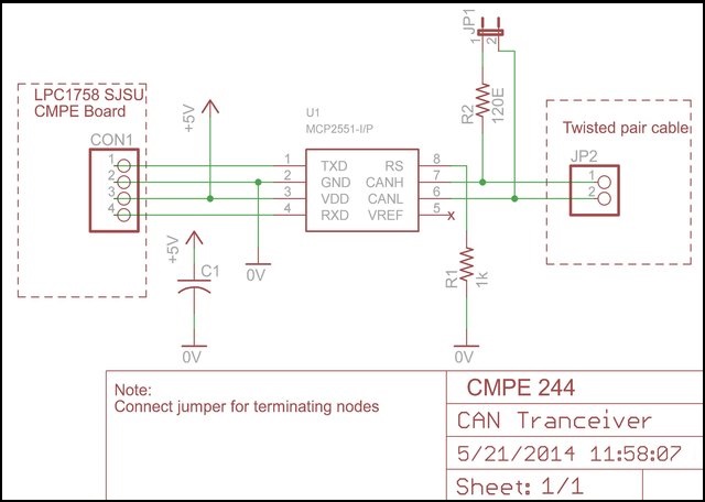
| + | |||
| + | The CAN transceiver board converts the digital logic signals into differential transmit and receive CAN protocol signals, and is fully compatible with the ISO-11898 standard. | ||
| + | |||
| + | The schematic of the transceiver is as follows: | ||
| + | |||
| + | [[File:CmpeE244_S14_T7_SchematicTranceiver.jpg]] | ||
=== Hardware Interface === | === Hardware Interface === | ||
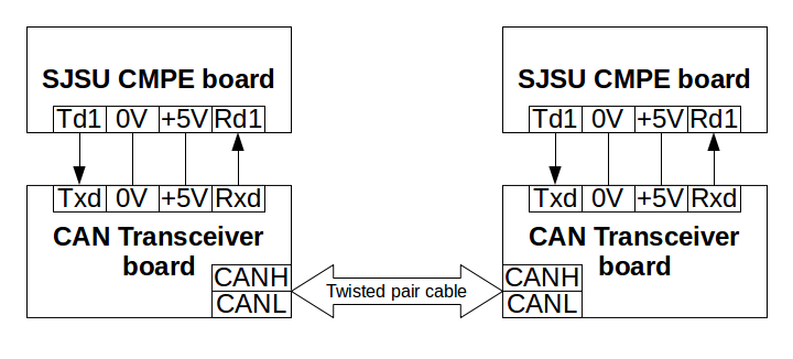
| − | + | The following diagram explains the hardware communication: | |
| + | |||
| + | [[File:CmpeE244_S14_T7_BlockDiagram.png]] | ||
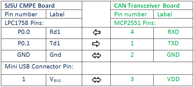
| − | + | The connections are made as follows: | |
| − | |||
| − | === Implementation === | + | [[File:CmpeE244_S14_T7_ConnectionsTable.PNG]] |
| − | + | ||
| + | === Software Design and Implementation === | ||
| + | |||
| + | In this project a bin file is transferred from Master SJSUOne board to Slave SJSUOne board via CAN. Both of these boards are connected to CAN transceivers as explained in hardware section and these transceivers are connected to each other through can bus. For the software implementation of this project we are using concepts like - | ||
| + | |||
| + | 1. CAN driver | ||
| + | |||
| + | 2. IAP | ||
| + | |||
| + | 3. File access API | ||
| + | |||
| + | |||
| + | '''1. CAN driver -''' | ||
| + | |||
| + | Controller Area Network is a very deterministic communication bus which is heavily used in automotive industry. It is a differential pair half duplex bus. 100K, 250K, 500K or 1Mbit speed are the standards. We are using 100Kbit speed in out project. Each frame of CAN data contains 0 to 8 bytes of data in it and has 11bit or 29bit message ID. We are using 1 or 8 bytes of data in CAN frames and are also using 11 bit messageID. | ||
| + | |||
| + | First step in software part implementation of this project is development of CAN driver. We have reused the CAN driver present in the software project which was part of the setup provided by Prof. Kang in http://www.socialledge.com/sjsu/index.php?title=Development_Package. CAN drivers are implemented in can.c and can.h. These files are uploaded as a part of Master project and Slave project. Steps to implement can driver - | ||
| + | |||
| + | i. Use the files named can.c and can.h provided in the setup. These files has the basic CAN driver functionality. | ||
| + | |||
| + | ii. Check whether transceivers are working by using self- loop test at both the master and slave end separately. If self-test loop is working then it means that transceiver connection with the board is working. There is a function named 'bool CAN_test2(void )' in can.c file (in the Master project)and this function can be used to test self-test loop functionality. | ||
| + | |||
| + | '''2. IAP-''' | ||
| + | |||
| + | A boot loader's main functionality is to copy a bin file from external memory like external flash to internal flash when the program is executing. When we load a program from Hyperload to SJSUOne board through USB/UART wire IAP is used to flash the bin file from PC to internal flash. We are using this same functionality to flash bin file from external flash to internal flash. The only difference is that when hyperload is used USB and UART is used to transfer the data while in our project we are using CAN to transfer bin file. Steps to use IAP - | ||
| + | |||
| + | i. Use Flash Magic to flash IAP project into SJSUOne board(SJSUOne board already has this project flashed into it, this set maybe be required if modifications in done to this project). Project named 'lpc1758_Hyperload_uart_sdcard_spiflash' which is provided in the setup files of SJSUOne board has the IAP functionality. This file has to be flashed into SJSUOne board's internal flash and after flashing this file occupies first 64k byte of memory. | ||
| + | |||
| + | ii. Any running program can start IAP functionality by calling 'chip_program_from_filename((const char*)&pFilename);' . Here, pFilename is the file path of the bin file which has to flashed into the internal flash. After this function call 'sys_reboot()' has to be called to restart the system. When this restart is done the newly flashed project starts executing. | ||
| + | |||
| + | '''3. File access API-''' | ||
| + | |||
| + | SJSUOne board has Micro SD card slot and LPC1758 processor has external flash of size 1mb. File I/O tutorial in http://www.socialledge.com/sjsu/index.php?title=SJ_One_Board can be read to get an idea how to use file system APIs. 'ff.c' file provides the functions to read and write files into micro-sd card or external flash. | ||
| + | |||
| + | |||
| + | '''Master State Diagram''' - | ||
| + | |||
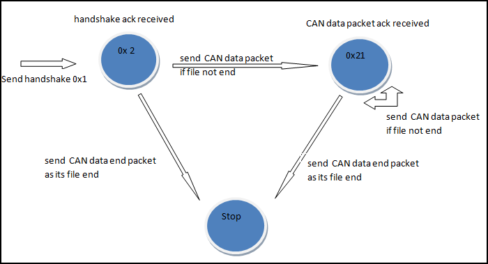
| + | [[File:CmpeE244_S14_T7_MasterStateDiagram.png]] | ||
| + | |||
| + | '''Slave State Diagram''' - | ||
| + | |||
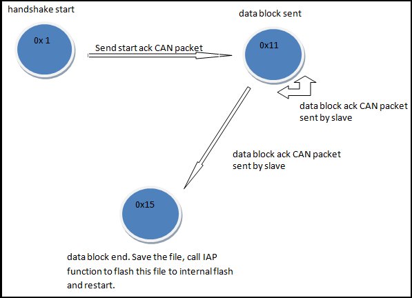
| + | [[File:CmpeE244_S14_T7_SlaveStateDiagram.png]] | ||
| + | |||
| + | |||
| + | '''Implementation steps''' - | ||
| + | |||
| + | 1. Build hardware as described in hardware section. | ||
| + | |||
| + | 2. Download the project setup given in http://www.socialledge.com/sjsu/index.php?title=Development_Package. This project setup contains CAN driver files (can.c and can.h). | ||
| + | |||
| + | 3. Check whether hardware is working using 'CAN_test2' function in our uploaded project (it is given in the Project source Code section of this page). | ||
| + | |||
| + | 4. Save the bin file (file which has to be sent to slave) in micro-sd card of Master SJSUOne board. Using Master state diagram as reference implement state diagram code logic in master project. Read the bin saved in sd card and start sending the data as per state diagram. | ||
| + | |||
| + | 5. At the receiver end implement slave state diagram code logic and save the can messages received from master data in external flash. Once the whole file is transferred send this newly created file's path to IAP function and restart. Once restart is done newly flashed bin is executed. | ||
== MOM == | == MOM == | ||
| Line 155: | Line 320: | ||
2) Get resistors and assemble CAN setup by 3/15 | 2) Get resistors and assemble CAN setup by 3/15 | ||
3) Test and modify existing CAN driver by 3/21 | 3) Test and modify existing CAN driver by 3/21 | ||
| + | |||
| + | (We tried to document MOM of our project meeting and work plans updation here. We didn't follow it up after sometime.) | ||
== Testing & Technical Challenges == | == Testing & Technical Challenges == | ||
| − | |||
| − | |||
| − | + | == Hardware Issues == | |
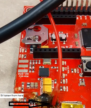
| + | 1. Can transceiver needs 5V source and it was difficult to source it. Since we are lazy we sourced this 5V from SJSUOne board's USB connector. | ||
| + | |||
| + | [[File:CmpeE244_S14_T7_SJSUOne5V.png]][[File:CmpeE244_S14_T7_SJOneBoard5VGlue.jpeg|right]] | ||
| + | |||
| + | 2. The wiring used in hardware part of the project used to come off easily and we used proper connectors to avoid this. We also used hot glue to make this wiring stable. | ||
| + | |||
| + | 3. We faced hardware issue when we were trying to take demo video. We changed twisted pair cable before the demo to increase the look and feel of the hardware but this resulted in us spending whole night just before the demo debugging this issue. There was a problem in twisted pair connection and we realized this after few longs hours of debugging. | ||
| + | |||
| + | == Software Issues == | ||
| + | 1. CAN driver taken from the setup was not working initially. Few small changes were required in it. Can files in uploaded projects works properly and can be used for any can projects. Prof. Kang and Sowmya helped in resolving this issue. | ||
| + | |||
| + | 2. Initially the idea was to send 512 bytes at a time from master to slave and get back the acknowledgement byte from slave for every 512 bytes of data sent. But this was resulting in buffer overflow error at the receiver end because the speed at which receiver used to take data from hardware register was slow compared to the speed at which master used to send the data. To avoid this problem acknowledgment data was sent from slave to master every time when it received data packet. This helped in adding synchronization to the communication protocol. | ||
| + | |||
| + | 3. Initially hex file was sent from master to slave and it was tried to flash. But we realized later on that bin file has to be sent and hex or elf shouldn't be sent as these formats add extra data in the file. | ||
| + | |||
| + | ==Future Enhancement== | ||
| + | 1. State diagram logic in Master and Slave can be implemented using tasks. CAN interrupt handler should communicate with the task using semaphore and should use queue to pass the CAN data. This task should process the data once it gets from ISR. | ||
| + | |||
| + | 2. Sensor reception logic can implemented as a separate task and this task can me made to co exist with boot loader task. | ||
| − | + | 3. This project can be scaled to work with multiple slaves. | |
| − | |||
== Conclusion == | == Conclusion == | ||
| − | + | This project was a good learning experience for us. We got an idea about CAN driver. We understood the basic functionality of a boot loader and how it actually works. We understood the flow of project flashing through hyper load and CAN and this understanding of IAP helped us to understand the flow of project compilation to project execution. | |
| + | This project can be further improved as our present implementation had basic working functionality. | ||
=== Project Video === | === Project Video === | ||
| − | + | Our project demo has been published at - https://www.youtube.com/watch?v=FjCvMMhLQpo&feature=youtu.be | |
| + | In this demo we are uploading master project and slave project in their respective SJSUOne board. Once the master sends bin file to slave it stops and once the slave receives the bin file sent by master it copies this file from external flash to internal flash using IAP and starts executing from it after restart. | ||
| + | |||
| + | === Project Hardware Setup === | ||
| + | |||
| + | [[File:CmpeE244_S14_T7_HardwareSetup_1.jpg]] | ||
=== Project Source Code === | === Project Source Code === | ||
| − | + | * [https://sourceforge.net/projects/sjsu/files/CmpE244_SJSU_S2014/ Sourceforge source code link] | |
== References == | == References == | ||
=== Acknowledgement === | === Acknowledgement === | ||
| − | + | We would like to sincerely thank Prof. Preetpal Kang for taking up this course and thereby providing us the opportunity to learn new things. | |
| + | We would also like to appreciate other classmates for the help during project work especially other teams working on projects based on CAN. | ||
=== References Used === | === References Used === | ||
List any references used in project. | List any references used in project. | ||
| − | + | #Preetpal Kang, Lecture notes of CMPE 244, Computer Engineering, Charles W. Davidson College of Engineering, San Jose StateUniversity, Feb-May 2014. | |
| − | + | #Project setup provided by Prof. Preetpal Kang. | |
| − | + | #http://elm-chan.org/fsw/ff/en/lseek.html | |
| + | #LPC1758 User Manual | ||
| + | #MCP2551 schematic: http://www.fischl.de/arm/can_bus_interface_for_stellaris_launchpad/ | ||
| + | #http://www.socialledge.com/sjsu/ | ||
Latest revision as of 23:41, 6 August 2014
Contents
Project Title
CAN Firmware Uploader
Abstract
Designing a method to load firmware through CAN bus. Master device will be able to load firmware in a slave device.
Objectives & Introduction
The main objective of this project is to design a CAN boot loader protocol. The firmware will be stored in .bin format in the SD card and this card will be connected to master device. This bin file will be transferred from master device to slave device through CAN bus. The receiver board flashes this received bin file into internal flash from external flash using IAP once this file transfer process is completed and restarts to start executing from this newly flashed bin file.
Block Diagram:
Team Members & Responsibilities
- Pradyumna Upadhya
- CAN Bus Driver Software Design
- In Application Programming
- Yash Parulekar
- Hardware Design
- SPI Flash Driver Software Design
Schedule
| Sl. No | Start Date | End Date | Task | Actual | |
|---|---|---|---|---|---|
| 1 | 2/25 | 2/28 | Order CAN Transceiver | Completed | |
| 2 | 3/1 | 3/7 | Procure Components | Completed | |
| 3 | 3/8 | 3/14 | Build H/w and read on establishing CAN communication | Completed.Hardware built. Plan to test it with CAN driver by 3/22 | |
| 4 | 3/15 | 3/21 | Design CAN protocol and Establish SIMPLE CAN communication | Completed on 4/17. We faced few problems in CAN driver and hardware. | |
| 5 | 3/22 | 3/28 | Read/Develop about SPI Flash driver to read and write .bin files | Completed on 4/21. Integrating bin reading logic with CAN driver. | |
| 6 | 3/29 | 4/11 | Transmit .bin file by integrating SPI driver and CAN | Ongoing. Tried sending sample bin to the receiver board. File save logic at receiver is being implemented now. As of now facing few sync problems in CAN ISR. Completed on 5/1/2014. | |
| 7 | 4/12 | 4/18 | Read about IAP | Completed on 4/22 | |
| 8 | 4/19 | 4/25 | Implement IAP | Completed on 4/22. It has to be integrated with CAN transfer state diagram logic. | |
| 9 | 4/26 | 5/5 | Testing and remove bugs, further enhancements | Ongoing. Completed testing on 5/1/2014. Further enhancements could not be done due to time constraints. | |
| 10 | 5/8 | 5/8 | Demo | Demo is on 5/22/2014. Wiki page update going on. Demo will be given at 5/22/2014 6pm and Wiki page updation will be completed by 6pm. |
Parts List & Cost
| Parts | Quantity | Rate | Cost* |
|---|---|---|---|
|
SJ One Board[1] |
2 |
$80 |
$160.00 |
|
MCP2551 |
2 |
$1.02 |
$2.04 |
|
Resistors(1K x2,120E x2) |
4 |
- |
$1.00 |
|
Capacitors (1nF x2) |
2 |
- |
$1.00 |
|
Screw Connectors |
2 |
$0.50 |
$1.00 |
|
Wires and Cables |
- |
- |
$1.00 |
|
TOTAL |
166.04 |
Design & Implementation
Hardware Design
Hardware features of SJSU One board used:
1. External Atmel DataFlash AT45DB08
This is used on all slave controllers. This is as a temporary storage for the CAN firmware (.bin file) received by the slave over CAN bus.
2. Micro SD Card interface
This is used on the master controller. The master reads the CAN firmware (.bin) files from the SD card.
3. LPC1758 (CAN module and SSP module)
This is the microcontroller for the system
4. Mini-USB Connector
VBUS pin of this connector is used to power the MCP2551 IC on the CAN Transceiver board. The SJSU CMPE Board is powered over this connector. The 5V obtained from VBUS pin of this connector is used to power the MCP2551 IC on the CAN Transceiver board.
CAN Transceiver Board:
The CAN transceiver board converts the digital logic signals into differential transmit and receive CAN protocol signals, and is fully compatible with the ISO-11898 standard.
The schematic of the transceiver is as follows:
Hardware Interface
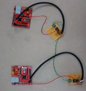
The following diagram explains the hardware communication:
The connections are made as follows:
Software Design and Implementation
In this project a bin file is transferred from Master SJSUOne board to Slave SJSUOne board via CAN. Both of these boards are connected to CAN transceivers as explained in hardware section and these transceivers are connected to each other through can bus. For the software implementation of this project we are using concepts like -
1. CAN driver
2. IAP
3. File access API
1. CAN driver -
Controller Area Network is a very deterministic communication bus which is heavily used in automotive industry. It is a differential pair half duplex bus. 100K, 250K, 500K or 1Mbit speed are the standards. We are using 100Kbit speed in out project. Each frame of CAN data contains 0 to 8 bytes of data in it and has 11bit or 29bit message ID. We are using 1 or 8 bytes of data in CAN frames and are also using 11 bit messageID.
First step in software part implementation of this project is development of CAN driver. We have reused the CAN driver present in the software project which was part of the setup provided by Prof. Kang in http://www.socialledge.com/sjsu/index.php?title=Development_Package. CAN drivers are implemented in can.c and can.h. These files are uploaded as a part of Master project and Slave project. Steps to implement can driver -
i. Use the files named can.c and can.h provided in the setup. These files has the basic CAN driver functionality.
ii. Check whether transceivers are working by using self- loop test at both the master and slave end separately. If self-test loop is working then it means that transceiver connection with the board is working. There is a function named 'bool CAN_test2(void )' in can.c file (in the Master project)and this function can be used to test self-test loop functionality.
2. IAP-
A boot loader's main functionality is to copy a bin file from external memory like external flash to internal flash when the program is executing. When we load a program from Hyperload to SJSUOne board through USB/UART wire IAP is used to flash the bin file from PC to internal flash. We are using this same functionality to flash bin file from external flash to internal flash. The only difference is that when hyperload is used USB and UART is used to transfer the data while in our project we are using CAN to transfer bin file. Steps to use IAP -
i. Use Flash Magic to flash IAP project into SJSUOne board(SJSUOne board already has this project flashed into it, this set maybe be required if modifications in done to this project). Project named 'lpc1758_Hyperload_uart_sdcard_spiflash' which is provided in the setup files of SJSUOne board has the IAP functionality. This file has to be flashed into SJSUOne board's internal flash and after flashing this file occupies first 64k byte of memory.
ii. Any running program can start IAP functionality by calling 'chip_program_from_filename((const char*)&pFilename);' . Here, pFilename is the file path of the bin file which has to flashed into the internal flash. After this function call 'sys_reboot()' has to be called to restart the system. When this restart is done the newly flashed project starts executing.
3. File access API-
SJSUOne board has Micro SD card slot and LPC1758 processor has external flash of size 1mb. File I/O tutorial in http://www.socialledge.com/sjsu/index.php?title=SJ_One_Board can be read to get an idea how to use file system APIs. 'ff.c' file provides the functions to read and write files into micro-sd card or external flash.
Master State Diagram -
Slave State Diagram -
Implementation steps -
1. Build hardware as described in hardware section.
2. Download the project setup given in http://www.socialledge.com/sjsu/index.php?title=Development_Package. This project setup contains CAN driver files (can.c and can.h).
3. Check whether hardware is working using 'CAN_test2' function in our uploaded project (it is given in the Project source Code section of this page).
4. Save the bin file (file which has to be sent to slave) in micro-sd card of Master SJSUOne board. Using Master state diagram as reference implement state diagram code logic in master project. Read the bin saved in sd card and start sending the data as per state diagram.
5. At the receiver end implement slave state diagram code logic and save the can messages received from master data in external flash. Once the whole file is transferred send this newly created file's path to IAP function and restart. Once restart is done newly flashed bin is executed.
MOM
MOM1 Date: 3/14 1) Read about CAN code by 3/15 2) Get resistors and assemble CAN setup by 3/15 3) Test and modify existing CAN driver by 3/21
(We tried to document MOM of our project meeting and work plans updation here. We didn't follow it up after sometime.)
Testing & Technical Challenges
Hardware Issues
1. Can transceiver needs 5V source and it was difficult to source it. Since we are lazy we sourced this 5V from SJSUOne board's USB connector.
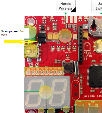
2. The wiring used in hardware part of the project used to come off easily and we used proper connectors to avoid this. We also used hot glue to make this wiring stable.
3. We faced hardware issue when we were trying to take demo video. We changed twisted pair cable before the demo to increase the look and feel of the hardware but this resulted in us spending whole night just before the demo debugging this issue. There was a problem in twisted pair connection and we realized this after few longs hours of debugging.
Software Issues
1. CAN driver taken from the setup was not working initially. Few small changes were required in it. Can files in uploaded projects works properly and can be used for any can projects. Prof. Kang and Sowmya helped in resolving this issue.
2. Initially the idea was to send 512 bytes at a time from master to slave and get back the acknowledgement byte from slave for every 512 bytes of data sent. But this was resulting in buffer overflow error at the receiver end because the speed at which receiver used to take data from hardware register was slow compared to the speed at which master used to send the data. To avoid this problem acknowledgment data was sent from slave to master every time when it received data packet. This helped in adding synchronization to the communication protocol.
3. Initially hex file was sent from master to slave and it was tried to flash. But we realized later on that bin file has to be sent and hex or elf shouldn't be sent as these formats add extra data in the file.
Future Enhancement
1. State diagram logic in Master and Slave can be implemented using tasks. CAN interrupt handler should communicate with the task using semaphore and should use queue to pass the CAN data. This task should process the data once it gets from ISR.
2. Sensor reception logic can implemented as a separate task and this task can me made to co exist with boot loader task.
3. This project can be scaled to work with multiple slaves.
Conclusion
This project was a good learning experience for us. We got an idea about CAN driver. We understood the basic functionality of a boot loader and how it actually works. We understood the flow of project flashing through hyper load and CAN and this understanding of IAP helped us to understand the flow of project compilation to project execution. This project can be further improved as our present implementation had basic working functionality.
Project Video
Our project demo has been published at - https://www.youtube.com/watch?v=FjCvMMhLQpo&feature=youtu.be In this demo we are uploading master project and slave project in their respective SJSUOne board. Once the master sends bin file to slave it stops and once the slave receives the bin file sent by master it copies this file from external flash to internal flash using IAP and starts executing from it after restart.
Project Hardware Setup
Project Source Code
References
Acknowledgement
We would like to sincerely thank Prof. Preetpal Kang for taking up this course and thereby providing us the opportunity to learn new things. We would also like to appreciate other classmates for the help during project work especially other teams working on projects based on CAN.
References Used
List any references used in project.
- Preetpal Kang, Lecture notes of CMPE 244, Computer Engineering, Charles W. Davidson College of Engineering, San Jose StateUniversity, Feb-May 2014.
- Project setup provided by Prof. Preetpal Kang.
- http://elm-chan.org/fsw/ff/en/lseek.html
- LPC1758 User Manual
- MCP2551 schematic: http://www.fischl.de/arm/can_bus_interface_for_stellaris_launchpad/
- http://www.socialledge.com/sjsu/
