Difference between revisions of "S19: Automophiles"
Proj user3 (talk | contribs) (→Lost transmission) |
Proj user3 (talk | contribs) (→Automophiles) |
||
| (218 intermediate revisions by 2 users not shown) | |||
| Line 1: | Line 1: | ||
| − | == | + | == Automophiles == |
* [https://gitlab.com/cmpe-243-group/cmpe-243-self-driving-car/ Automophiles] | * [https://gitlab.com/cmpe-243-group/cmpe-243-self-driving-car/ Automophiles] | ||
| − | == Abstract == | + | |
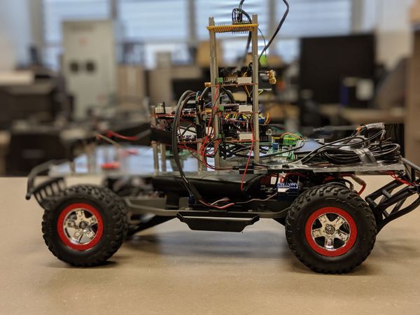
| + | [[File:CMPE243_S19_Automophiles Self_Driving_Car_Left.jpeg|600x600px|thumb|left]] | ||
| + | |||
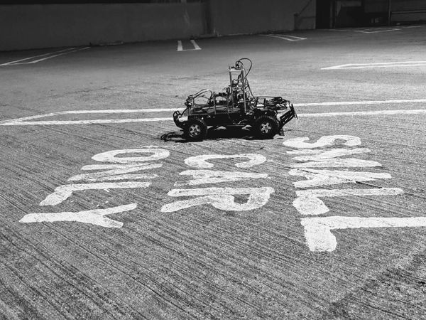
| + | [[File:CMPE_243_S19_Automophiles_Self_Driving_Car_centre.jpg|600x600px|thumb|center]] | ||
| + | |||
| + | |||
| + | === Abstract === | ||
Automophiles is a an autonomous RC car capable of navigating to destination set from Android application with obstacle avoidance and GPS navigation along certain routes on the SJSU campus. The embedded system driving the car is essentially a distributed system of different nodes communicating with one another and each focusing on a specific task such as polling sensor data, driving motor or monitoring GPS location data. These nodes are then integrated into a functional vehicle on the CAN bus exchanging meaningful data and commands to drive the car. | Automophiles is a an autonomous RC car capable of navigating to destination set from Android application with obstacle avoidance and GPS navigation along certain routes on the SJSU campus. The embedded system driving the car is essentially a distributed system of different nodes communicating with one another and each focusing on a specific task such as polling sensor data, driving motor or monitoring GPS location data. These nodes are then integrated into a functional vehicle on the CAN bus exchanging meaningful data and commands to drive the car. | ||
| Line 18: | Line 24: | ||
=== Team Members & Responsibilities === | === Team Members & Responsibilities === | ||
| − | |||
* Sensor | * Sensor | ||
| Line 182: | Line 187: | ||
| | | | ||
* <font color="red"> Figure out the cut off values to take left/right turns and fine tune those values.</font> | * <font color="red"> Figure out the cut off values to take left/right turns and fine tune those values.</font> | ||
| + | * <font color="magenta">Decide and Experiment with different cut-off values from sensor to command right / left / straight to motor.</font> | ||
* <font color="magenta">Build obstacle avoidance state machine in Master controller</font> | * <font color="magenta">Build obstacle avoidance state machine in Master controller</font> | ||
* <font color="blue">Test motor responsiveness in hallway testing</font> | * <font color="blue">Test motor responsiveness in hallway testing</font> | ||
| Line 198: | Line 204: | ||
| | | | ||
* <font color="blue">Mount RPM sensor on DC motor and do ramp testing</font> | * <font color="blue">Mount RPM sensor on DC motor and do ramp testing</font> | ||
| − | * <font color=" | + | * <font color="magenta">Figure out the normal speed of car on flat surface, in order to send speed value to motor.</font> |
| + | * <font color="magenta">Streamline and verify obstacle avoidance on uphill and downhill ramp tests</font> | ||
| + | * <font color="red">Check whether sensors are detecting ground surface on ramp or not and change offset accordingly.</font> | ||
* <font color="purple">Mount compass on RC car and transmit calibrated heading on CAN bus</font> | * <font color="purple">Mount compass on RC car and transmit calibrated heading on CAN bus</font> | ||
* <font color="purple">Mount GPS with external antenna on RC car and transmit GPS fix and current coords</font> | * <font color="purple">Mount GPS with external antenna on RC car and transmit GPS fix and current coords</font> | ||
| Line 244: | Line 252: | ||
* Finalize wiki report | * Finalize wiki report | ||
| | | | ||
| − | + | Completed | |
| | | | ||
| − | + | 5/14/19 | |
|- | |- | ||
! scope="row"| 15 | ! scope="row"| 15 | ||
| Line 253: | Line 261: | ||
* '''Final Demo''' | * '''Final Demo''' | ||
| | | | ||
| − | + | Completed | |
| | | | ||
| − | + | 5/22/19 | |
|} | |} | ||
| Line 335: | Line 343: | ||
== Printed Circuit Board == | == Printed Circuit Board == | ||
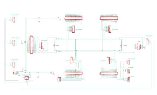
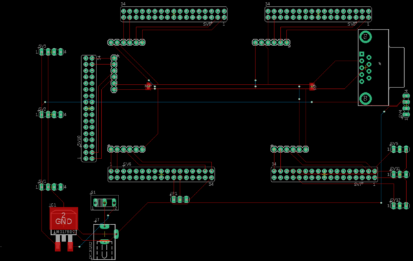
| − | + | The PCB schematic and layout was designed using the available Eagle software. For fabrication purpose, it was converted to Gerber zip file. Further, uploaded the printed circuit board (PCB) design files and received a Design for Manufacturability (DFM) report from one of the online tool available on the Bay area circuits website. This automated tool identifies possible production issues enabling us to address areas of concern prior to beginning the manufacturing process. Multi-layered printed circuit boards (PCBs) are typically preferred since they offer high signal intensity. Of all the multi-layered types, the 2-layer PCB is the most common, as it can accommodate interconnects on both sides. So, the PCB that we designed was a 2 layer PCB. | |
| − | <br> | + | [[ File: CmpE243_S19_Automophiles_PCB_schematic.png|600px|thumb|center|| PCB Schematic with all the five controller units]] <br> |
| + | [[ File: CmpE243_S19_Automophiles_PCB_layout.png|600px|thumb|center|| PCB Layout]] | ||
== CAN Communication == | == CAN Communication == | ||
| − | + | ||
| + | Each controller has its own block of CAN message IDs, with master and motor commands/feedback taking highest priority at the early 100s block. Compass messages come in at the 110 block with current heading and debug, and gps information takes up the rest of the 100 block. Starting at the 200 ID block, sensor readings come in. MIA management only really comes into play for messages that are expected to be regularly received such as sensor values and motor commands. Certain one-time messages such as destination latlng and bridge_headlights don't have MIA management. | ||
=== Hardware Design === | === Hardware Design === | ||
| − | + | [[File:CmpE243_S19_Automophiles_System_can_diagram.jpg|750x900px|thumb|center]] | |
| + | |||
| + | |||
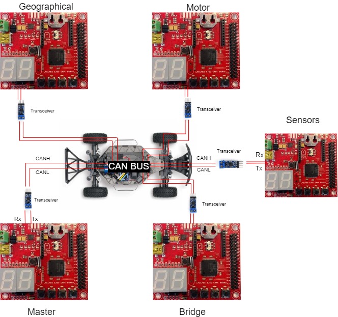
| + | All five SJone boards are connected to each other through the CAN Bus. The Master controls the activity of all the boards. It takes in data through the CAN Bus from the Sensors, GPS and Bridge Module and commands the Motor module. | ||
=== DBC File === | === DBC File === | ||
| Line 397: | Line 410: | ||
SG_ NEXT_CHECKPOINT : 0|8@1+ (1,0) [0|0] "" BRIDGE | SG_ NEXT_CHECKPOINT : 0|8@1+ (1,0) [0|0] "" BRIDGE | ||
| − | BO_ 200 | + | BO_ 200 SENSOR_READINGS: 8 SENSOR |
SG_ SENSOR_FRONT : 0|16@1+ (1,0) [0|0] "milimeters" BRIDGE,MASTER | SG_ SENSOR_FRONT : 0|16@1+ (1,0) [0|0] "milimeters" BRIDGE,MASTER | ||
SG_ SENSOR_LEFT : 16|16@1+ (1,0) [0|0] "milimeters" BRIDGE,MASTER | SG_ SENSOR_LEFT : 16|16@1+ (1,0) [0|0] "milimeters" BRIDGE,MASTER | ||
SG_ SENSOR_RIGHT : 32|16@1+ (1,0) [0|0] "milimeters" BRIDGE,MASTER | SG_ SENSOR_RIGHT : 32|16@1+ (1,0) [0|0] "milimeters" BRIDGE,MASTER | ||
| − | SG_ SENSOR_LEFT_BLOCKED : | + | SG_ SENSOR_BACK : 48|16@1+ (1,0) [0|0] "milimeters" BRIDGE,MASTER |
| − | SG_ SENSOR_CENTER_BLOCKED : | + | |
| − | SG_ SENSOR_RIGHT_BLOCKED : | + | BO_ 205 SENSOR_DEBUG_MESSAGES: 1 SENSOR |
| − | SG_ SENSORS_HEARTBEAT : | + | SG_ SENSOR_LEFT_BLOCKED : 0|1@1+ (1,0) [0|0] "" BRIDGE,MASTER |
| + | SG_ SENSOR_CENTER_BLOCKED : 1|1@1+ (1,0) [0|0] "" BRIDGE,MASTER | ||
| + | SG_ SENSOR_RIGHT_BLOCKED : 2|1@1+ (1,0) [0|0] "" BRIDGE,MASTER | ||
| + | SG_ SENSOR_BACK_BLOCKED : 3|1@1+ (1,0) [0|0] "" BRIDGE,MASTER | ||
| + | SG_ SENSORS_HEARTBEAT : 4|1@1+ (1,0) [0|0] "" BRIDGE,MASTER | ||
BO_ 300 BRIDGE_STOP: 1 BRIDGE | BO_ 300 BRIDGE_STOP: 1 BRIDGE | ||
| Line 441: | Line 458: | ||
</pre> | </pre> | ||
| + | |||
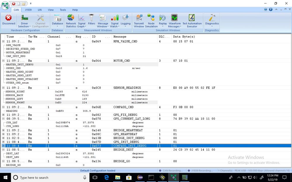
| + | === BusMaster Can Bus Messages === | ||
| + | |||
| + | [[File: CmpE243_S19_Automophiles_busmaster.jpeg|1000x1200px|center|thumb|Busmaster screenshot]] | ||
== Sensor ECU == | == Sensor ECU == | ||
| Line 451: | Line 472: | ||
''' Sensor Introduction ''' | ''' Sensor Introduction ''' | ||
| − | We have used ''' | + | |
| + | We have used '''VL53L0X Time of Flight(ToF) Ranging Sensor''' by ST Microelectronics, which offers several advantages over Ultrasonic sensor counterparts. It can measure absolute distances up to 2m in its long range mode. Four different modes of operation namely '''Default mode''', '''High Speed mode''', '''High Accuracy mode''' and '''Long Range mode''' make it customizable for suitable applications. | ||
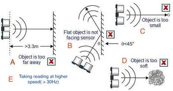
[[File:Ultrasonic_limitations.jpg|350x200px|thumb|Limitations of Ultrasonic]] | [[File:Ultrasonic_limitations.jpg|350x200px|thumb|Limitations of Ultrasonic]] | ||
| + | |||
==== Advantage of Laser Sensor over popular Ultrasonics ==== | ==== Advantage of Laser Sensor over popular Ultrasonics ==== | ||
| − | Ultrasonic Sensors are quite popular in use in this class, but they have several limitations described in the picture | + | Ultrasonic Sensors are quite popular in use in this class, but they have several limitations described in the picture next. VL53L0X Laser sensor avoids limitations B, D, E very easily in the following ways |
| − | * B : Even if obstacle surface is tilted to more than 60 degrees, laser would still detect it and give the distance reading accordingly. | + | * B: Even if obstacle surface is tilted to more than 60 degrees, the laser would still detect it and give the distance reading accordingly. |
| − | * D : Light can be passed through soft surfaces. | + | * D: Light can be passed through soft surfaces. |
| − | * E : In High speed mode, we can get reliable sensor values even at 50Hz frequency. | + | * E: In High-speed mode, we can get reliable sensor values even at 50Hz frequency. |
* Laser sensor beam has Field of View(FOV) of 25 degrees which is suitable in our left, center and right set up and it doesn't add interference between center-right pair or center-left pair like Ultrasonic; hence, all three sensor readings can be taken simultaneously. | * Laser sensor beam has Field of View(FOV) of 25 degrees which is suitable in our left, center and right set up and it doesn't add interference between center-right pair or center-left pair like Ultrasonic; hence, all three sensor readings can be taken simultaneously. | ||
| + | The sensor values range from 0 to 8190 in millimeters, 0 being the lowest value and 8190 being the free value. Any value above 2200 mm was given to be the free value of 8190. | ||
| + | |||
'''Problem Resolution''' | '''Problem Resolution''' | ||
| − | + | The sensor should be fast enough to detect rapid obstacles movement in all 3 primary directions; i.e. forward, right and left. In order to do that, all 3 front sensors should be taking readings at the minimum 20Hz frequency, but faster the better. As laser sensor doesn't work based on the reflected wave like ultrasonic, there is no interference even if two centers are next to each other and simultaneous readings are taken. Hence, we were able to take simultaneous readings from all sensors. Sensor data is obtained on the I2C bus, hence, all sensors are operated as a slave with different Slave address and Sensor ECU is Master on I2C bus. | |
=== Hardware Design === | === Hardware Design === | ||
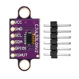
| + | [[File:CMPE_243_S19_Automophiles_Time_of_Flight_Sensors.jpg|160px|right|thumb|Time Of Flight Sensors]] | ||
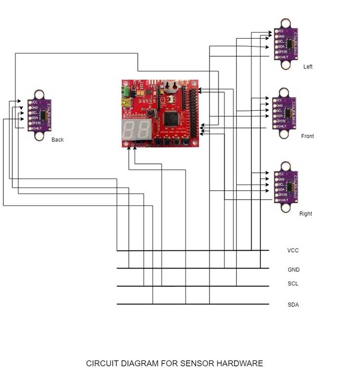
| + | Our Self Driving Car consists of 4 VL53L0X, time of flight sensors. Three of them mounted on the front for the Front, Left and Right obstacles and one for the obstacles on the back. | ||
| + | The time of flight consists of 6 pins named, Vcc, GND, SCL, SDA, GPIO and XSHUT respectively. | ||
| + | We use 5 pins out of those 6 such that the GPIO is left unused. | ||
| + | |||
| + | |||
| + | The Time of Flight sensors uses I2C such that the I2C transmits data and clock with SDA and SCL pins. Both these pins are open drain which means I2C master and slave devices can only drive these lines low or leave them open. For this reason, more than one slave can communicate at the same time. The XSHUT pin is connected to a GPIO pin on the SJone board. | ||
| + | |||
| + | The XSHUT pin controls the register address of the sensor. The GPIO that is connected first gets the default address. We can change the address at the boot time of the sensor. | ||
| + | This is used when more than one sensor is used, which is the case for us. | ||
| + | |||
| + | |||
| + | [[File:CMPE_243_S19_Automophiles_Circuit_Diagram_for_Sensor_Hardware.jpg|700px|centre|thumb|Circuit Diagram for Sensor Hardware]] | ||
=== Software Design === | === Software Design === | ||
| − | + | [[File:CmpE243_S19_Automophiles_Sensor_software_flow.jpg|520px|thumb|left|Sensor Software Flow]] | |
| + | |||
| + | [[File:CmpE243_S19_Automophiles_Sensor_structs123.png|400px|thumb|center|Sensor structs]] | ||
| + | |||
| + | |||
| + | |||
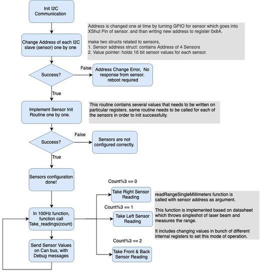
| + | The Sensor module works on I2C communication. Once the I2C communication is initialized, we change the address of each I2C slave one by one. The Address is changed one at a time by turning the GPIO for the sensors on. This pin goes to the XSHUT pin for the sensor. We write a new address to the register 0x8A. | ||
| + | |||
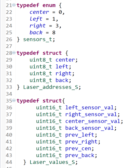
| + | We make two structs for the sensors. | ||
| + | 1. Sensor address struct: which contains Address of all 4 sensors. | ||
| + | 2. Value pointer that holds 16 sensor values for each sensor. | ||
| + | |||
| + | If it is not a success, It throws an address change error, thus, rebooting the sensor module. If it succeeds, the sensors are configured. | ||
| + | |||
| + | 100 Hz Function: | ||
| + | |||
| + | We take the sensor value readings every count % 3 times. Inside the function, readRangeSingleMillimetres() function is called with the sensor address passed as argument. | ||
| + | This function is implemented based on datasheet which throws singleshot of the laser beam and measures the range. It includes the changing values in a bunch of different internal registers to set this mode of operation. | ||
| + | |||
| + | In Count%3==0, we take the right sensor reading. Similarly, in Count%3==1 and Count%3==2 we take left sensor and front and back sensor reading respectively. We send the sensor values on the CAN Bus with the Debug Messages. | ||
| + | |||
| + | === Problems & Solutions === | ||
| + | '''Problem1:''' We were facing trouble changing the address of I2C slave(sensor). The default address of sensor was getting responded, but after changing the address to particular value; i.e. say 0x66, the sensor wasn't responding with that address. | ||
| + | |||
| + | '''Solution 1:''' It turned out whenever value as the address was written on I2C register, it was internally right shifting that value and setting the shifted value as address of the sensor. Hence, we have to give the value left shifted by one. | ||
| + | |||
| + | |||
| + | '''Problem 2:''' As Laser sensors don't have interference in case of adjacent sensors, we tried running it at 50Hz, simultaneously taking two sensor values, but values were not consistent. | ||
| + | |||
| + | '''Solution 2:''' After referring to the datasheet of the sensor, it was known that in default mode, taking one sensor reading takes 30 ms of time. Hence, we could take sensor values at 33Hz. We also found out that using High-speed mode can allow us to execute sensors at 50Hz but with less accuracy. | ||
| + | |||
| + | |||
| + | '''Problem 3:''' One main problem we faced was the center couldn't detect the standing person's feet or pole which is not that wide and has a lesser radius. In this case, another sensor might require to successfully detect thin obstacles by increasing its accuracy. | ||
| − | |||
| − | |||
| − | |||
| + | '''Problem 4:''' Another problem we faced was with the 3D mounting of the sensor modules which were mounted on a declined angle such that the sensor didn't detect a value farther than 750 mm, so we had to bump down our steer distances and thus our servos were having a problem and therefore car ended up hitting the obstacle. | ||
| + | '''Solution 4:''' We could improve the design of the 3D mounts such that the angle could be about 5 degrees. That would have helped us solve this issue. | ||
<HR> | <HR> | ||
| Line 479: | Line 548: | ||
== Motor Controller & LCD == | == Motor Controller & LCD == | ||
| − | https://gitlab.com/cmpe-243-group/cmpe-243-self-driving-car/tree/master/Motor | + | '''Gitalb link''' |
| + | |||
| + | https://gitlab.com/cmpe-243-group/cmpe-243-self-driving-car/tree/master/Motor | ||
==== Group Members ==== | ==== Group Members ==== | ||
| Line 485: | Line 556: | ||
* ''' Alisha Jean Patrao ''' | * ''' Alisha Jean Patrao ''' | ||
* ''' Sanjana Devegowdanakoppalu Swamy Gowda ''' | * ''' Sanjana Devegowdanakoppalu Swamy Gowda ''' | ||
| + | |||
| + | |||
| + | Motor controller is designed to execute functions as commanded by the master. Motor controller performs operations to steer in any direction by driving the dc motor consistently and also performs reverse operations. This unit drives the dc motor and steers servo wheels by increasing or decreasing the pulse width modulation. | ||
| + | |||
| + | LCD unit is used display useful data regarding the motor operation. This is interfaced to our SJ One board with the help of UART protocol. | ||
=== Hardware Design === | === Hardware Design === | ||
[[File:Untitled Diagram.png]] | [[File:Untitled Diagram.png]] | ||
| − | === Software Design === | + | === Design & Implementation === |
| + | |||
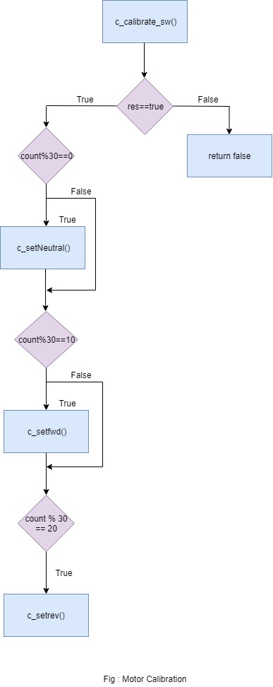
| + | Motor controller module plays an important role in our project. The motion of servo motor and dc motor is provided by this module.Motor controller in our design communicates only with the master module. This module handles several servo various commands given by master such as steer right, left, slight left, slight right. It also handles dc motor commands such as forward, reverse, stop and brake. DC motor needs a calibration before we start any of the motor operations. In our project we have calibrated the dc and servo motor to run at 100Hz. | ||
| + | |||
| + | '''DC motor Calibration''' | ||
| + | |||
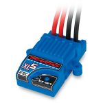
| + | The EZ button on the XL5 needs to be long pressed until the LED light changes from flashing green to solid red. Once the LED reaches this state, the LED blinks red light once this indicates that the neutral value is latched. After this the LED blinks red once more indicating the maximum forward PWM value of the dc motor is set. Now the LED goes blinking green indicating that maximum reverse PWM value of the dc motor is set. Our dc motor has a neutral PWM value of 15%, it can go upto maximum forward PWM value of 21.8% and reverse maximum PWM value of 5%. This initial calibration sequence is included in our init function so that every time the dc motor is turned on this init sequence is executed because providing the neutral value is a prime thing to be done. | ||
| + | [[File:dcmotor.jpeg|200x150px|right|thumb|DC Motor]] | ||
| + | |||
| + | === DC Motor === | ||
| + | [[File:esc.jpeg|200x150px|right|thumb|ESC]] | ||
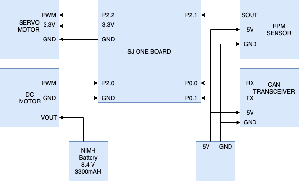
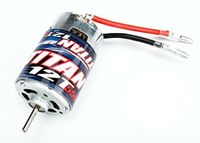
| + | Our RC car has a Titan 12T motor embedded in it. Titan 12T motors are used in single motor and single battery pack.Any FreeRTOS tasks can use this motor and it provides voltage up to 8.4 volts. DC Motor is powered up using the 5V supply.The car is driven either forward or backward by setting the different PWM values with varied duty cycles. The DC motor converts electrical signal to mechanical power. The PWM signal from the Sjone Board is given ESC(Electronic Speed Control). For reverse mechanism, there is a separate flow of operations. The dc motor as to be provided with the neutral value, give a delay, then a reverse value, delay and reverse value. Regular operations such as driving fowrard does not require any delay, but an initial neutral value should be given before starting the motor. | ||
| + | |||
| + | === ESC === | ||
| + | [[File:servo.jpeg|200x150px|right|thumb|Servo Motor]] | ||
| + | ESC is an electronic circuit that controls and regulates the speed of an electric motor. It also provides reversing of the motor tasks and dynamic braking. It also consists of EZ push button which is prominently used in motor calibration. We also use this button to turn on and off the DC motor. The EZ button also provides three different modes of operation Sports mode( 100% Forward, 100% Brakes, 100% Reverse), Race mode(100% Forward, 100% Brakes, No Reverse) and Training mode( 50% Forward, 100% Brakes, 50% Reverse). We have always kept our car in training mode in all our cases. An electronic speed control has 3- sets of wires. The signal and Gnd pins of DC motor are connected to the pin 2.0 and Gnd pins of the Sjone Board. Since the VCC pin of XL5 outputs a higher voltage than 5v, for the safety of sj one board we ignore the vcc wire of dc motor. | ||
| + | |||
| + | |||
| + | |||
| + | |||
| + | === Servo Motor === | ||
| + | [[File:rpm.jpg|200x150px|right|thumb|Rpm Sensor]] | ||
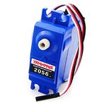
| + | Our RC car has a servo motor embedded in it. The Servo motor is used to drive the front pair of wheels using power supply. We provide varied PWM values from sj one board. The different values of PWM are used to turn the wheels right or left. The servo motor is running at a frequency of 100HZ. Servo motor has three wires namely gnd, vcc and signal. Signal wire is connected to P2.2 of sj one..The Vcc and Gnd pins of servo are connected to the Vcc and Gnd pins of the Sjone Board. | ||
| + | |||
| + | === RPM Sensor === | ||
| + | [[File:lcd.jpg|200x150px|right|thumb|LCD Module]] | ||
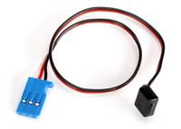
| + | Traxaas 6520 Rpm Sensor was is in our car to monitor the speed . The rpm sensor is mounted to the car using a Traxaas 6537 wire retainer closer to the DC motor. The sensor works on the Hall Effect principle.The sensor comes with a single magnet and the idea here is every time the motor completes one rotation the magnet moves closer to the sensor, the sensor will send an high pulse during this phase until the magnet moves away from it. This give us the number of rotations per second.The signal pin,Vcc and Gnd pins of the Rpm Sensor are interfaced to the P2.1, Vcc and Gnd pins of the sj one Board. We get the number of rotation every one millisecond. This sensor is used move the motor consistently on an uphill, down hill and on a flat surface. | ||
| + | |||
| + | |||
| + | |||
| + | |||
| + | |||
| + | |||
| + | === LCD Module Interface === | ||
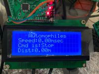
| + | LCD module is used to display information such as the speed at which our motor is running, the command received by master and distance remaining to the destination. This is a 4x20 matrix LCD. Serial LCD driver is interfaced with SJ one board using Universal Asynchronous Transmitter and Receiver protocol. The TXD and RXD pins of the serial LCD is connected to RXD2 and TXD2 pins of the micro controller respectively with a 5v power supply. | ||
| + | |||
| + | Sj one board is initialized with baud rate, TX and RX queue size. Serial LCD module is initialized by sending a baud of 0xF0 that will be detected by Sj one board. Later we will invoke functions which will print speed in msec, command and distance in m on the serial LCD driver. The LCD module picture shows a sample of the initial values of the motor module before the motor module is initiated. | ||
| + | |||
| + | |||
| + | |||
| + | |||
| + | |||
| + | === Software Design === | ||
| + | The Motor module acts on the commands it receives from the Master module. Basic directions are controlled by the Servo Motor and the forward,reverse movements are controlled by the DC Motor. | ||
| + | |||
| + | *Initialization of motor and LCD module is done in the C_period_init function. Motor is initialized to work in 100Hz and neutral PWM value is provided. LCD unit is initialized to 38400 baud rate. CAN communication is also initialized by providing baud, Rx and Tx queue sizes. | ||
| + | |||
| + | *In 1Hz task, we check if motor module is able to perform CAN communication. If it has reached a bus_off state we reset the CAN bus. The contents that needs to be printed on LCD is performed in this task | ||
| + | |||
| + | *In 10Hz task, we check if master is commanding reverse and perform reverse if master asks for it. We execute reverse function by setting the reverse flag to true if master commands reverse. | ||
| + | |||
| + | *In 100Hz task, we perform CAN communication. The motor speed is continuously monitored every 250 millisecond to check if the number of rotations per second is enough to maintain the speed. There is a dedicated function which provides the number of rotations per second.We also check the status and if the reverse flag value is false, we use the decoded message sent by master and execute relevant functions. | ||
| + | |||
| + | [[File: CmpE243_S19_Automophiles_Motor_Calibration.jpeg|500px|left|thumb|Motor Calibration]] | ||
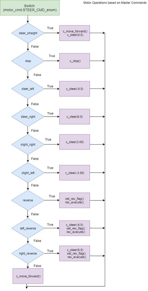
| + | [[File: CmpE243_S19_Automophiles_MotorOperations_MasterCommands.jpeg|500px|right|thumb|MotorOperation based on Master Commands]] | ||
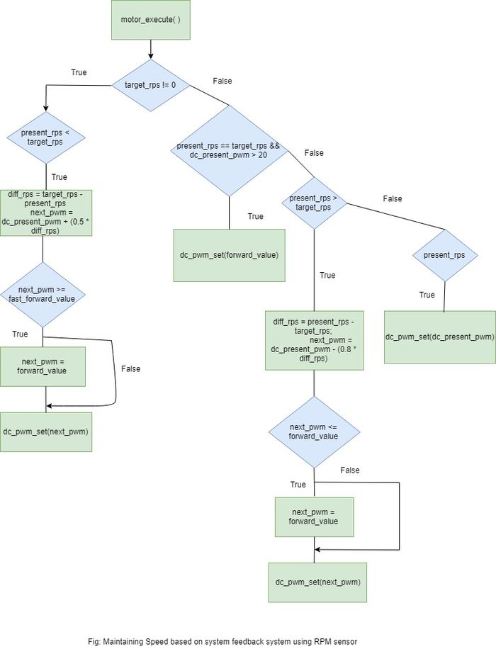
| + | [[File: CmpE243_S19_Automophiles_RPM_Sensor.jpeg|700px|center|thumb|RPM Sensor Flowchart]]<br><br><br><br> | ||
| + | Motor Calibration flowchart explains the sequence of the dc motor calibration. This is accomplished by by providing relevant PWM values with delay in between them. | ||
| + | |||
| + | Motor Operations based on master commands explains the actions taken by motor module. It performs actions such as right, left, slight left, align etc. The respective PWM values are set based on the functions called. | ||
| + | |||
| + | RPM sensor flow chart explains PID logic. We check for the number of rotations per second and compare it with target rotations per second. If the values are not equal we increase the PWM value gradually. Similar steps is taken taken when present number of rotations is more than the target rotations per second to decrease the PWM gradually. | ||
=== Technical Challenges === | === Technical Challenges === | ||
| + | * '''Understanding PWM class:''' | ||
| + | '''Problem Summary''' : Initially, the dc motor did not work as expected. The dc motor is initialized to run at 100Hz frequency. We did not have clear understanding of how the frequency of dc and servo motor is set and how pwm class constructor is initialized. We had given two different frequencies for both servo and dc. After a lot of trial and errors, the servo motor worked as expected, not the dc. | ||
| + | |||
| + | '''Solution''' : We realized that once dc/servo motor's frequency is set first, the same frequency is also set for the servo/dc motor. There is no concept of two unique frequency values for servo and dc. Both servo and dc works at same frequency, whichever modules frequency is set first, the same value goes for other one too. | ||
| + | |||
| + | |||
| + | * '''DC Motor Calibration:''' | ||
| + | '''Problem Summary''' : Initially it was hard for us to figure out what is range of actual PWM value to move forward for the dc motor with a given frequency. Trying random PWM values did not help. | ||
| + | |||
| + | '''Solution''' : We approached this problem in two ways after we read the traxxas manual for calibration sequence. First we wrote a for loop to check for which number will the ESC's LED will change from flashing green to solid red, this gave us the neutral PWM value. Similarly we waited for another LED red blink to check the forward maximum PWM and noted it down. The second approach is that wrote a terminal command(complete trial and error method) to set to a particular frequency and provided a lot of values to check if the neutral value got latched. We got to know about the neutral value from the for loop method. The neutral value can also be found using an oscilloscope. | ||
| + | |||
| − | + | * '''Reverse Logic:''' | |
| − | + | '''Problem Summary''' : When the dc motor logic is to drive forward and master commands a reverse, our motor stopped. It did not move at all until we restarted the module. | |
| − | |||
| − | |||
| + | '''Solution''' : Reverse logic unlike forward logic needs to go through few states for the reverse operation. Then, we figured out that the dc motor needs a neutral PWM value before reverse PWM being set. We should provide a neutral value which is basically our stop command. We had to give a minimum delay of 0.3s after the neutral value and then provide reverse PWM value. We had three states for reverse logic, stop -> reverse -> reverse for smooth reverse operation. | ||
<HR> | <HR> | ||
<BR/> | <BR/> | ||
== Geographical Controller == | == Geographical Controller == | ||
| + | |||
| + | Link: https://gitlab.com/cmpe-243-group/cmpe-243-self-driving-car/tree/master/GPS | ||
| + | |||
| + | ==== Group Members ==== | ||
| + | * '''Kevin Gadek''' | ||
| + | * '''Nivedita Shiva Murthy''' | ||
| + | * '''Alisha Jean Patrao''' | ||
| + | |||
Geographical Controller is used for the navigation of the vehicle to reach from its current location to the desired destination. This can be achieved by using the GPS module and the Compass module. | Geographical Controller is used for the navigation of the vehicle to reach from its current location to the desired destination. This can be achieved by using the GPS module and the Compass module. | ||
| Line 516: | Line 670: | ||
Tracking - to keep track of the vehicle movement | Tracking - to keep track of the vehicle movement | ||
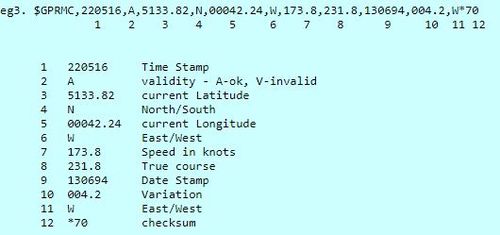
| + | Our GPS module outputs NMEA sentences containing several pieces of useful information as shown below. The most relevant parts of this sentence are located in the first half of the sentence. | ||
| + | [[File: CmpE243_S19_Automophiles_gprmc_parse_ss.JPG|500px|left|thumb|Sample GPS parsing]] | ||
| + | |||
| + | <br><br><br><br><br><br><br><br><br><br><br><br><br><br><br><br> | ||
'''Compass:''' | '''Compass:''' | ||
| − | Compass has a small magnetic needle suspended that rotates freely around a fixed axis until it settles pointing towards magnetic north. The major task performed using a compass is to calculate the difference of angle between the source and destination location then navigate/direct it accordingly. The LSM303D combines a digital 3-axis accelerometer and 3-axis magnetometer into a single package that is ideal for making a tilt-compensated compass. The six independent readings, whose sensitivities can be set in the ranges of ±2 to ±16 g and ±2 to ±12 gauss, are available through I²C and SPI interfaces. | + | Compass has a small magnetic needle suspended that rotates freely around a fixed axis until it settles pointing towards magnetic north. The major task performed using a compass is to calculate the difference of angle between the source and destination location then navigate/direct it accordingly. The LSM303D combines a digital 3-axis accelerometer and 3-axis magnetometer into a single package that is ideal for making a tilt-compensated compass. The six independent readings, whose sensitivities can be set in the ranges of ±2 to ±16 g and ±2 to ±12 gauss, are available through I²C and SPI interfaces. I2C was used in our case as a better API is provided for reading and writing registers over I2C rather than over SPI. Several config registers need to be set in initialization to set reading resolution, update rate and power-on state of the compass. For the purposes of this project, the update rate of the compass is set to 50Hz with low resolution. After that, the only initialization action is to enable the continuous conversion mode of the compass. |
| − | |||
| − | |||
| − | |||
| − | |||
| − | |||
| − | |||
=== Hardware Design === | === Hardware Design === | ||
| Line 535: | Line 687: | ||
=== Software Design === | === Software Design === | ||
| − | |||
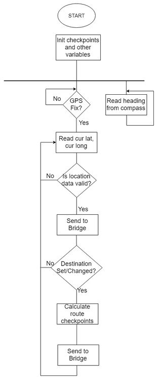
The Geographical Controller's software design consists of several main periodic tasks, gps_1Hz(), gps_50Hz(), and compass_50Hz(). | The Geographical Controller's software design consists of several main periodic tasks, gps_1Hz(), gps_50Hz(), and compass_50Hz(). | ||
| + | |||
| + | * 1 Hz | ||
| + | ** Reset CAN bus if bus off | ||
| + | |||
| + | * 10 Hz | ||
| + | ** Build route checkpoints array if isCheckpointsDone bool is false and destination is set | ||
| + | |||
| + | * 25 Hz | ||
| + | ** Parse latest gps NMEA sentence and store curLat and curLong. Once a sufficient number of bytes is read over UART from the gps module, strtok is applied with a delimiter of ',' to essentially deconstruct the NMEA sentence and pull the latitude and longitude values. Rather than using the hardware Fix pin provided by the module, the parser is able to determine whether there is a GPS fix by looking at one of the tokens of the NMEA sentence. An 'A' indicates valid data while a 'V' indicates the latter. The values for latitude and longitude are provided in decimal format and must be converted into coordinates such as {37.125678, -121.892098}. Once the conversion is complete, these coords are then sent on the CAN bus. If the CAN_rx loop in this function also returns a destination, the gps_25Hz() callback also computes checkpoints to be added to a global route_checkpoints array. These checkpoints are then stepped through to determine the target distance and bearing that the car should go to reach the next selected checkpoint. There will eventually come a case where there are no more checkpoints along the route but the car is still not at the destination. When this happens, gps_25Hz() will simply transmit the target heading and distance straight to the destination. The target distance and bearing calculations used are outlined below. Sample code for stepping through the route_checkpoints array to calculate target bearing and distance is given below. | ||
| + | <pre> | ||
| + | void next_checkpoint_handler(void) | ||
| + | { | ||
| + | target_heading = calculate_target_heading(curLat, curLong, route_checkpoints[nextCheckpointIndex][0], route_checkpoints[nextCheckpointIndex][1]); | ||
| + | target_distance = calculate_target_distance(curLat, curLong, route_checkpoints[nextCheckpointIndex][0], route_checkpoints[nextCheckpointIndex][1]); | ||
| + | geo_can_tx_target_heading_distance(target_heading,target_distance); | ||
| + | if(target_distance < 5) //5 meters away from our current checkpoint, set next checkpoint to aim for | ||
| + | { | ||
| + | nextCheckpointIndex++; | ||
| + | } | ||
| + | } | ||
| + | </pre> | ||
| + | |||
| + | [[File:CmpE243_S19_Automophiles_gps_checkpoints.JPG|300px|center]] | ||
| + | |||
| + | * 50 Hz | ||
| + | ** Read latest compass heading and send on CAN bus. The LSM303D provides three 16-bit values corresponding to magnetic x-axis, magnetic y-axis and magnetic z-axis that are each available to users in 8-bit high and low registers. These values can then be used to calculate current compass heading based on the formula described below. If an offset is required in order to make the compass more accurate, this 50Hz task also provides a way for a manual switch press to set an offset that can then be applied to the compass readings. This was only deemed necessary in the early stages of compass software development and has not been used since. | ||
| + | |||
| + | [[File: CmpE243_S19_Automophiles_gps_sw_flow_chart.jpg|500x750px|thumb|center]] | ||
| + | |||
| + | ==== Necessary calculations ==== | ||
| + | '''Compass Heading formula:''' | ||
| + | <pre> | ||
| + | mx = (int16_t) i2c2_read_reg(COMPASS_DEVICE_ADDR, OUT_X_H_M) << 8 | i2c2_read_reg(COMPASS_DEVICE_ADDR, OUT_X_L_M); | ||
| + | my = (int16_t) i2c2_read_reg(COMPASS_DEVICE_ADDR, OUT_Y_H_M) << 8 | i2c2_read_reg(COMPASS_DEVICE_ADDR, OUT_Y_L_M); | ||
| + | curHeading = atan2(my,mx); | ||
| + | if(curHeading < 0) | ||
| + | { | ||
| + | curHeading += 2 * M_PI; | ||
| + | } | ||
| + | curHeading = ((curHeading * 180)/M_PI); | ||
| + | //apply a calibration offset | ||
| + | if(calibrated) | ||
| + | { | ||
| + | curHeading -= cal_offset; | ||
| + | } | ||
| + | curHeading = 360 - curHeading; | ||
| + | //adjust value until it's within 0-360 range | ||
| + | if(curHeading < 0) | ||
| + | { | ||
| + | curHeading = 360 + curHeading; | ||
| + | } | ||
| + | |||
| + | </pre> | ||
| + | |||
| + | '''Target Heading formula:''' | ||
| + | deltaLngRad = destLngRad - curLngRad | ||
| + | x = sin(deltaLngRad) * cos(destLatRad) | ||
| + | y = cos(curLatRad) * sin(destLatRad) - sin(curLatRad) * cos(destLatRad) * cos(deltaLngRad) | ||
| + | targetHeading = fmodf(to_degree(atan2(x,y)) + 360, 360) | ||
| + | |||
| + | '''Target Distance formula:''' | ||
| + | deltaLatRad = destLatRad - curLatRad | ||
| + | deltaLngRad = destLngRad - curLngRad | ||
| + | a = sin(deltaLatRad/2) * sin(deltaLatRad/2) + cos(curLatRad) * cos(destLatRad) * sin(deltaLngRad/2) * sin(deltaLngRad/2) | ||
| + | c = 2 * atan2(sqrt(a), sqrt(1-a)) | ||
| + | targetdistance = R * c | ||
| + | where R = 6371 * (10^3) | ||
| + | |||
| + | '''Route checkpoint formula:''' | ||
| + | <pre> | ||
| + | uint8_t calculate_initial_checkpoint(float cur_lat, float cur_long) | ||
| + | { | ||
| + | //u0_dbg_printf("calculate_initial_checkpoint\n"); | ||
| + | //car to dest or most recently selected route checkpoint to destination | ||
| + | bool isThereInitialCheckpoint = false; | ||
| + | uint8_t checkpoint_index = 0; | ||
| + | float src_distance_to_dest = calculate_target_distance(cur_lat, cur_long, savedDestLat, savedDestLong); | ||
| + | float car_distance_to_checkpoint, checkpoint_distance_to_dest; | ||
| + | float shortest_checkpoint_distance = GPS_CHECKPOINT_MAX_DISTANCE; | ||
| + | //loop through all our checkpoints and find the closest one to our src that also closes the distance to dest | ||
| + | for(int i = 0; i < NUM_CHECKPOINTS; i++) | ||
| + | { | ||
| + | //cur_lat and cur_long are current car coords | ||
| + | car_distance_to_checkpoint = calculate_target_distance(cur_lat, cur_long, gps_checkpoints[i][0], gps_checkpoints[i][1]); | ||
| + | checkpoint_distance_to_dest = calculate_target_distance(gps_checkpoints[i][0], gps_checkpoints[i][1], savedDestLat, savedDestLong); | ||
| + | if((checkpoint_distance_to_dest < src_distance_to_dest) && (car_distance_to_checkpoint < shortest_checkpoint_distance)) | ||
| + | { | ||
| + | //led_set(2, true); | ||
| + | shortest_checkpoint_distance = car_distance_to_checkpoint; | ||
| + | checkpoint_index = i; | ||
| + | isThereInitialCheckpoint = true; | ||
| + | } | ||
| + | } | ||
| + | //only if there is a checkpoint that satisfies the above conditions can we say there is an initial checkpoint and can add to route_checkpoints | ||
| + | if(isThereInitialCheckpoint) | ||
| + | { | ||
| + | //u0_dbg_printf("init %d\n", checkpoint_index); | ||
| + | route_checkpoints[0][0] = gps_checkpoints[checkpoint_index][0]; | ||
| + | route_checkpoints[0][1] = gps_checkpoints[checkpoint_index][1]; | ||
| + | route_checkpoints[0][2] = checkpoint_index; | ||
| + | numRouteCheckpoints++; | ||
| + | return checkpoint_index; | ||
| + | } | ||
| + | else | ||
| + | { | ||
| + | //returning this magic number means we didn't find a checkpoint, assume it's just a straight line to dest | ||
| + | return DEFAULT_CHECKPT_IDX; | ||
| + | } | ||
| + | |||
| + | } | ||
| + | |||
| + | </pre> | ||
| + | |||
| + | === Relevant CAN Messages === | ||
| + | <pre> | ||
| + | BO_ 120 GPS_CURRENT_LAT_LONG: 8 GPS | ||
| + | SG_ CUR_LAT : 0|32@1+ (0.000001,0.000000) [36.000000|38.000000] "degrees" BRIDGE,MASTER | ||
| + | SG_ CUR_LONG : 32|32@1+ (0.000001,-123.000000) [-123.000000|-120.000000] "degrees" BRIDGE,MASTER | ||
| + | |||
| + | BO_ 125 GPS_INIT_DEBUG: 1 GPS | ||
| + | SG_ INIT_DEBUG : 0|1@1+ (1,0) [0|0] "" MASTER | ||
| + | |||
| + | BO_ 130 GPS_FIX_DEBUG: 1 GPS | ||
| + | SG_ GPS_FIX_DEBUG : 0|1@1+ (1,0) [0|0] "" BRIDGE,MASTER | ||
| + | |||
| + | BO_ 135 COMPASS_MAN_CAL_DEBUG: 1 GPS | ||
| + | SG_ IS_CAL_DEBUG : 0|1@1+ (1,0) [0|0] "" MASTER | ||
| + | |||
| + | BO_ 140 GPS_HEARTBEAT: 1 GPS | ||
| + | SG_ GPS_HEARTBEAT : 0|1@1+ (1,0) [0|0] "" MASTER | ||
| + | |||
| + | BO_ 145 GPS_TARGET_HEADING: 8 GPS | ||
| + | SG_ TARGET_HEADING : 0|32@1+ (0.1,0) [0.00|360.00] "degrees" MOTOR,BRIDGE,MASTER | ||
| + | SG_ DISTANCE : 32|32@1+ (0.1,0) [0|0] "meters" MOTOR,BRIDGE,MASTER | ||
| + | |||
| + | BO_ 150 GPS_CHECKPOINT_INDEX: 1 GPS | ||
| + | SG_ NEXT_CHECKPOINT : 0|8@1+ (1,0) [0|0] "" BRIDGE | ||
| + | |||
| + | </pre> | ||
=== Technical Challenges === | === Technical Challenges === | ||
| Line 548: | Line 838: | ||
'''Summary:''' The time-to-first-fix interval is largely inconsistent regardless of whether a battery backup is attached to the GPS breakout. Sometimes, it may take several minutes to get a fix while at other times, almost instantaneously. Once it gets a fix, it may also take an inconsistent amount of time to report accurate locations. Location at first fix may be a kilometer off and then the GPS will take some time to slowly correct itself. Even after some time, the GPS might be slightly inaccurate as in it believes it's inside a building when it's actually a few dozen feet outside of it. This can cause issues when calculating target bearing and distance as an accurate understanding of the car's current location needs to be established to figure out where to go. | '''Summary:''' The time-to-first-fix interval is largely inconsistent regardless of whether a battery backup is attached to the GPS breakout. Sometimes, it may take several minutes to get a fix while at other times, almost instantaneously. Once it gets a fix, it may also take an inconsistent amount of time to report accurate locations. Location at first fix may be a kilometer off and then the GPS will take some time to slowly correct itself. Even after some time, the GPS might be slightly inaccurate as in it believes it's inside a building when it's actually a few dozen feet outside of it. This can cause issues when calculating target bearing and distance as an accurate understanding of the car's current location needs to be established to figure out where to go. | ||
| − | '''Resolution:''' | + | '''Resolution:''' A coin cell battery backup was added to allow the GPS module to keep track of time and satellite positions while the geo controller is off. This drastically reduces the time-to-first-fix interval as well as allows the gps module to provide more accurate readings in a shorter amount of time. In certain cases, the gps module was able to get a fix inside buidings with this battery backup hooked up as well. |
<HR> | <HR> | ||
| Line 554: | Line 844: | ||
== Communication Bridge Controller == | == Communication Bridge Controller == | ||
| − | + | https://gitlab.com/cmpe-243-group/cmpe-243-self-driving-car/tree/master/Bridge | |
| + | |||
| + | Bridge Controller is essentially the communication apparatus between the car and the Android application. Critical pieces of information such as destination latitude and longitude are received and processed in this controller before getting sent to the geographical controller. | ||
==== Group Members ==== | ==== Group Members ==== | ||
| Line 566: | Line 858: | ||
=== Software Design === | === Software Design === | ||
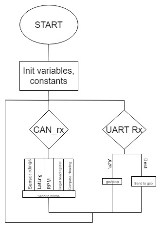
| − | + | The bridge's software design is a largely simple implementation of a CAN Rx and Uart Rx loop. A whole host of information useful to the rest of the car's system are also sent here as they may prove useful to display on the Android application. As such, inside the central CAN Rx loop and the dbc_decode switch logic, generalized UART transmit statements are used to transmit formatted data that was received onto the application. Essentially the same logic applies to the UART Rx loop, as the application may send information such as a 'bridge go/stop' or destination latlng which would ultimately get processed and ultimately forwarded to the necessary module such as geographical or master module. This general software flow is detailed below: | |
| + | |||
| + | [[File:CmpE243_S19_Automophiles_bridge_sw_chart.jpg|500px|center]] | ||
| + | |||
| + | |||
| + | ==== Relevant CAN messages ==== | ||
| + | <pre> | ||
| + | BO_ 300 BRIDGE_STOP: 1 BRIDGE | ||
| + | SG_ BRIDGE_STOP : 0|1@1+ (1,0) [0|0] "" MASTER | ||
| + | |||
| + | BO_ 310 BRIDGE_GO: 1 BRIDGE | ||
| + | SG_ BRIDGE_GO : 0|1@1+ (1,0) [0|0] "" MASTER | ||
| + | |||
| + | BO_ 315 BRIDGE_INIT_DEBUG: 1 BRIDGE | ||
| + | SG_ INIT_DEBUG : 0|1@1+ (1,0) [0|0] "" MASTER | ||
| + | |||
| + | BO_ 320 BRIDGE_HEARTBEAT: 1 BRIDGE | ||
| + | SG_ BRIDGE_HEARTBEAT : 0|1@1+ (1,0) [0|0] "" MASTER | ||
| + | |||
| + | BO_ 325 BRIDGE_DEST: 8 BRIDGE | ||
| + | SG_ DEST_LAT : 0|32@1+ (0.000001,0) [36.000000|38.000000] "degrees" GPS | ||
| + | SG_ DEST_LNG : 32|32@1+ (0.000001,-123) [-123.000000|-120.000000] "degrees" GPS | ||
| + | |||
| + | BO_ 330 BRIDGE_HEADLIGHTS: 1 BRIDGE | ||
| + | SG_ HEADLIGHT_VALUE : 0|1@1+ (1,0) [0|0] "" MASTER | ||
| + | </pre> | ||
==== Implementation ==== | ==== Implementation ==== | ||
| + | The bridge controller consists of the following periodic callbacks: | ||
* ''' In 1 Hz periodic ''' | * ''' In 1 Hz periodic ''' | ||
** Reset CAN bus if bus off | ** Reset CAN bus if bus off | ||
| Line 574: | Line 892: | ||
* ''' In 10 Hz ''' | * ''' In 10 Hz ''' | ||
| + | ** Receive all messages in CAN_rx loop | ||
| + | ** Receive all queued bytes on UART3 from Xbee module | ||
| + | ** Send UART messages to Bluetooth Xbee module depending on received CAN messages | ||
| + | |||
| + | The bridge is initialized to talk with the Xbee module at a standard 9600 baudrate. Because the transmission of bytes by the bridge controller and the reception of these bytes by the Android application can't necessarily be synchronized, a primitive implementation of a frame header is used by the bridge to let the app know what message it's about to receive. For instance, when bridge is about to send 12 bytes of data for 3 sensor float values, it first puts an 0x53 ('S') out on UART. Once the Android application's Bluetooth handler reads that byte, it knows to expect 12 bytes immediately after and knows what to do with them. For instance, it knows to read the next 4 bytes and convert those into a float for the left sensor value. While this works for the limited implementation of this project, it will ultimately fail as more and more types of data is sent to the application. Even with the half-a-dozen pieces of information received, corrupt data is already being seen from the application. For instance, this start of frame header can't be seen in another message's data or there will be a risk of lost data. A more professional implementation of this transmission protocol would be a more fully-featured header frame as well as a checksum at the end of message. However, the critical pieces of data sent back and forth over the Bluetooth socket are ultimately preserved and accurate over the course of this project. | ||
=== Technical Challenges === | === Technical Challenges === | ||
| − | |||
==== Lost transmission ==== | ==== Lost transmission ==== | ||
'''Summary:''' Even while using a start of frame byte to essentially tell the Android app what information it's getting and how many bytes to expect for that information, some information is lost or garbled. This data loss/corruption seems to depend on the frequency of which the bridge is running at. The faster the bridge runs at, the more non-sense seems to be sprinkled into the transmission, which can cause issues with debug panels. For instance, as sensor values are constantly getting transmitted to the app, the app's debug panel might show rapidly changing but accurate values, there are occasionally abnormally large values sprinkled in. | '''Summary:''' Even while using a start of frame byte to essentially tell the Android app what information it's getting and how many bytes to expect for that information, some information is lost or garbled. This data loss/corruption seems to depend on the frequency of which the bridge is running at. The faster the bridge runs at, the more non-sense seems to be sprinkled into the transmission, which can cause issues with debug panels. For instance, as sensor values are constantly getting transmitted to the app, the app's debug panel might show rapidly changing but accurate values, there are occasionally abnormally large values sprinkled in. | ||
| Line 587: | Line 909: | ||
== Master Module == | == Master Module == | ||
| − | |||
https://gitlab.com/cmpe-243-group/cmpe-243-self-driving-car/tree/master/Master | https://gitlab.com/cmpe-243-group/cmpe-243-self-driving-car/tree/master/Master | ||
| Line 594: | Line 915: | ||
* '''Sagar Kalathia''' | * '''Sagar Kalathia''' | ||
| − | === | + | === Software Design === |
| + | |||
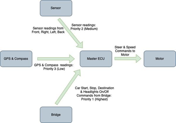
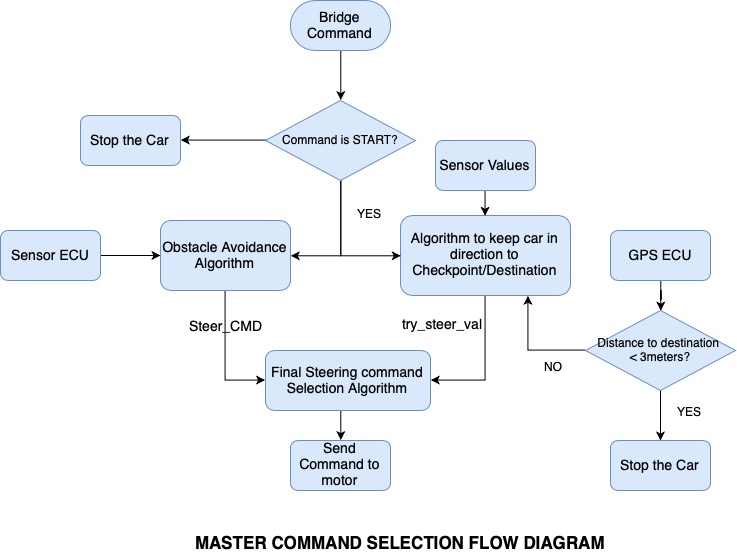
| + | Master Module is the brain of the car that takes critical decisions based on the Sensor data from surroundings and GPS coordinates; some of the critical decisions are the direction in which the car should be moving, the speed of the car, when to start the car, and when to stop / reverse. Master module is responsible to move the car to destination set in the Android application without crashing to any obstacles on the way. Master module makes this decision based on the input obtained from 3 different ECUs. | ||
| + | |||
| + | '''1. Bridge Controller''' It sends commands like Start car, stop car, Turn on/off Headlights. It basically acts as Starting and Stopping mechanism for the car, hence commands from Bridge Controller are given the higest priority in decesion making of Master module state machine. | ||
| + | |||
| + | '''2. Sensor Controller''' It sends sensor values in direction of front, right, left and rear sensors. After car has started and running, Obstacles need to be avoided first, hence, sesor data has given Priority 2 (Medium) in Master state machine. Obstacle avoidance mechanism in master ECU is based on these sensor data. | ||
| + | |||
| + | '''3. GPS Controller''' It sends current & target destination and compass headings to master module in order to keep the car on track and in direction and route closest to the destination. Obstacles need to avoid first and if there are no obstacle in our way, then car should try to move in the direction of destination; hence, GPS readings are given Priority 3 (lowest) in Master ECU. | ||
| + | Based on the data and commands from all the 3 ECU, Master decision making algorithm decides in which direction the car should be moving and at which speed. Master sends these steer and speed commands to Motor ECU. The whole Process flow is shown in the diagram below. | ||
| + | [[File:CmpE243_S19_Automophiles_Master_overall_flow.jpg|600px|thumb|left|Master Flow]] | ||
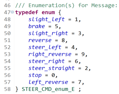
| + | [[File:CmpE243_S19_Automophiles_Ss_master.png|400px|thumb|center|Enumerations generated from dbc file]] | ||
| + | |||
| + | |||
| + | |||
| + | |||
| + | |||
| + | |||
| + | |||
| + | |||
| + | |||
| + | |||
| + | |||
| + | === Software Flowchart=== | ||
| + | ''' Obstacle Avoidance Algorithm Flowchart ''' | ||
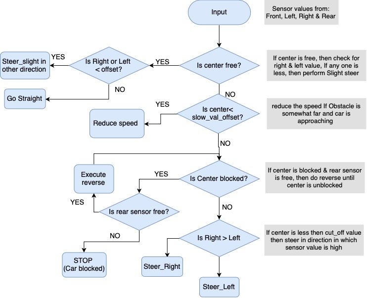
| + | *The Master needs to decide steer command based on Sensor, GPS and Compass data. Obstacle Avoidance algorithm decides where to steer based on sensor data obtained from center, right, left and rear censor. | ||
| + | [[File:CmpE243_S19_Automophiles_MasterOA1.jpg|750x900px|thumb|center|Obstacle Avoidance Algorithm Flowchart]] | ||
| + | |||
| + | ''' Master Command Selection Algorithm''' | ||
| + | In order for car to stay in direction to destination, Master decides based on following two values: Current Heading & Target Heading. | ||
| + | based on these values, algorithm would decide where car should move to keep directed towards destination. | ||
| + | After getting steer value to keep the car in direction of destination; i.e. steer_right, algorithm only checks for sensor value in that particular direction and not all sensor values. This will make the car on track quickly. If after processing compass heading values, if car should turn right and right sensor is free, then command would be steer right even when center sensor is free. This is due to the fact that Destination location or next checkpoint to be reached is on the right side. Master module also gets distance to destination value from GPS module, which helps master command motor to stop when destination is reached or car is within 1 meter radius of destination location. | ||
| + | |||
| + | [[File:CmpE243_S19_Automophiles_MASTER_CMD_SELECTION.jpg|750x900px|thumb|center|Master Command Selection Algorithm]] | ||
| − | === | + | === Technical Challenges & Solution=== |
| − | + | *'''Problem 1:''' Car was taking long time to steer in the direction of destination/next checkpoint. | |
| + | *'''Solution 1:''' After getting the steer value from compass headings, we were checking all the sensor values and if all are free, than only we were steering in direction of next checkpoint. We improved this algorithm by checking sensor value only in the direction where next checkpoint is; and if that particular sensor (right or left) is free, we steer in that direction irrespective of other sensor. This reduced the overhead of other sensor being less than free value due to fluctuations and made the car turn quickly in direction of next checkpoint/destination. | ||
| − | + | *'''Problem 2:''' We were facing difficulty in avoiding car to hit the wall facing directly in front. | |
| + | *'''Partial Solution 2:''' Even after adding braking command, car was hitting the wall. Hence, we tried moving to slower speed when center detects obstacle at 50 cm. This sort of worked in our case but still in some cases car was hitting the wall as our speed was slightly more than normal speed. | ||
| − | |||
| − | |||
| − | |||
| − | |||
<HR> | <HR> | ||
| Line 610: | Line 962: | ||
== Mobile Application == | == Mobile Application == | ||
| − | + | https://gitlab.com/cmpe-243-group/cmpe-243-self-driving-car/tree/master/Android | |
==== Group Members ==== | ==== Group Members ==== | ||
| Line 620: | Line 972: | ||
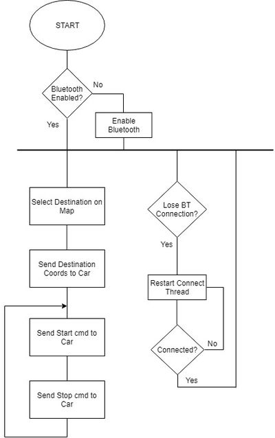
The application uses UI fragments to allow for better modularity and flexibility when building the application. In our case, all Google Map related activity could be constrained to MainActivity.java, all Bluetooth UI related activity to BluetoothFragment.java and Bluetooth background service activity to BluetoothService.java. Various UI layouts that are used such as activity_main.xml, bluetooth_fragment.xml and debug_popup.xml are subsequentially hooked up to these source files. This view-controller setup ensures a somewhat more focused interaction between Java source code and the various UI elements being hooked up. | The application uses UI fragments to allow for better modularity and flexibility when building the application. In our case, all Google Map related activity could be constrained to MainActivity.java, all Bluetooth UI related activity to BluetoothFragment.java and Bluetooth background service activity to BluetoothService.java. Various UI layouts that are used such as activity_main.xml, bluetooth_fragment.xml and debug_popup.xml are subsequentially hooked up to these source files. This view-controller setup ensures a somewhat more focused interaction between Java source code and the various UI elements being hooked up. | ||
| + | [[File:CmpE243_S19_Automophiles_app_flow_diagram.jpg|thumb|400px|center]] | ||
==== MainActivity.java ==== | ==== MainActivity.java ==== | ||
| − | The main focus of this code module is to hook up and interact with the Google Maps fragment as well as the toolbar at the top of the screen. activity_main.xml and debug_popup.xml are hooked up to this code module with the latter layout being displayed only when the debug button's onClickListener is invoked. | + | |
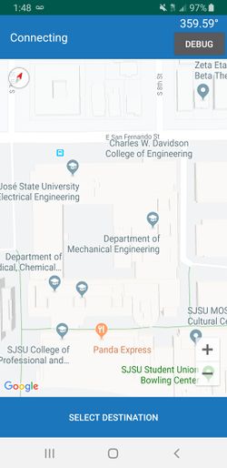
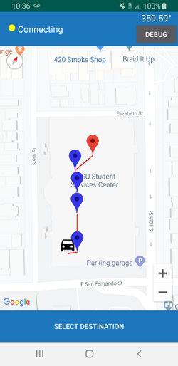
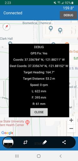
| + | The main focus of this code module is to hook up and interact with the Google Maps fragment as well as the toolbar at the top of the screen. activity_main.xml and debug_popup.xml are hooked up to this code module with the latter layout being displayed only when the debug button's onClickListener is invoked. An onClickListener is also implemented on the map to regard a clicked point on the map as the destination and essentially run the same route calculation as in the geo controller in order to display the selected checkpoints on the map fragment. | ||
{| | {| | ||
| Line 630: | Line 984: | ||
|[[File:CmpE243 S19 Automophiles app debug 2.jpg|thumb|250px|right]] | |[[File:CmpE243 S19 Automophiles app debug 2.jpg|thumb|250px|right]] | ||
|} | |} | ||
| + | |||
| + | MainActivity.java serves as the launching point of the entire application. From this module's onCreate method, all of the various UI elements such as the toolbar and Maps fragment are instantiated. The bluetooth fragment that inflates the primary button at the bottom of the app is also inserted within this method as well. MainActivity.java also provides many public methods to allow BluetoothFragment to update private member variables that will ultimately update MainActivity's various UI elements such as the toolbar and map. | ||
==== BluetoothFragment.java ==== | ==== BluetoothFragment.java ==== | ||
| − | The | + | The primary UI element of this source file is the central button at the bottom of the screen. This Bluetooth button has an onClickListener that is tied to the app's global state machine. Depending on the current state of the app transaction, the main Bluetooth button will vary between "Select Destination", "Send Destination", "Start" and "Stop". This module is also responsible for verifying that Bluetooth is enabled on the phone as well as starting the background BluetoothService module that is responsible for connecting and managing the actual socket connection. A message handler is defined in this file and is used in BluetoothService's constructor in order to provide a means for this fragment to communicate with BluetoothService. This is critical as all of the sent and received data that will go through the Bluetooth socket will at some point be forwarded through this handler. The fragment is also responsible for communicating with MainActivity in cases where the map would need to get updated with Bluetooth information, such as the car's current latitude and longitude. |
==== BluetoothService.java ==== | ==== BluetoothService.java ==== | ||
| + | |||
| + | This java module contains no UI elements but instead consists entirely of a helper class to connect and manage a Bluetooth socket connection. Two thread classes are defined with one (ConnectThread) dedicated entirely to discovering the HC-06 Xbee module with its specific MAC address and the other (ConnectedThread) devoted entirely to managing an active socket connection and processing received information. Both of these threads have try-catch blocks that are incredibly useful in cases such as where ConnectThread would need to continually be restarted until the HC-06 is available. ConnectedThread is launched once ConnectThread successfully connects to the vehicle. Its primary purpose is to allow BluetoothFragment to write bytes to the socket as well as handle received bytes. Once received bytes go through basic parsing and processing, such as conversion to floats or ints, this data is bundled into a message that is then sent over to BluetoothFragment's handler. From there, BluetoothFragment can decide what to do, such as updating MainActivity's UI elements or the app's transaction state. | ||
=== Technical Challenges === | === Technical Challenges === | ||
| Line 649: | Line 1,007: | ||
'''Resolution:''' The problem was likely caused by out-of-order bytes being received after the start of frame byte sent by the bridge is received. This issue largely went away after slowing down the bridge to 10Hz. | '''Resolution:''' The problem was likely caused by out-of-order bytes being received after the start of frame byte sent by the bridge is received. This issue largely went away after slowing down the bridge to 10Hz. | ||
| + | ==== Null value crashes ==== | ||
| + | '''Summary:''' Crashes were frequent at times as more debug information was added with their respective member variables instantiated to null. If BluetoothService didn't receive the information and tell MainActivity to set its member variables to these values, MainActivity could at times try to set a TextView to a null value and crash. These crashes would only pop up when the car was connected. | ||
| + | |||
| + | '''Resolution:''' This problem was easily remedied by doing != null checks before attempting to display the values. | ||
<HR> | <HR> | ||
| Line 654: | Line 1,016: | ||
== Conclusion == | == Conclusion == | ||
| − | + | This project was a very useful exercise in building an engineering product from the ground up. Components had to be largely sourced by ourselves and critical thinking skills had to be employed to address problems that sprang up. The kind of skills exercised over the course of this project are skills that are necessary to be successful in industry. In addition, working on a project as distributed as this one where certain members are solely focused on one specific module with little information on others is a tremendous exercise in building team skills. Having an understanding of the CAN format and its intricacies also acts towards broadening the knowledge base of all members involved, which is always useful regardless of any intention to work in the automotive or other industry where the CAN bus is used. | |
| − | |||
| − | |||
=== Project Video === | === Project Video === | ||
| + | https://youtu.be/o2EehIcVZT4 | ||
=== Project Source Code === | === Project Source Code === | ||
| Line 664: | Line 1,025: | ||
=== Advise for Future Students === | === Advise for Future Students === | ||
| − | + | ||
| + | * '''Splurge on sensors: ''' Having reliable sensors along with stable sensor mounts can go a long way towards dealing with obstacle avoidance. Having an idea of how selected sensors should be mounted and orientated and then creating a custom 3D printed mount to see that vision come to fruition can protect against problems down the road during crunch time. | ||
| + | |||
| + | * '''Pick compass carefully: ''' Pick a compass that can reliably produce accurate headings. Do research and read the datasheets on possible parts and don't simply buy the cheapest compass chip. A good and bad compass could make the difference between your car following a route well or going all over the place. | ||
| + | |||
| + | * '''Prepare for the worst: ''' Buy backup components, especially important ones such as a digital compass, RC car battery. Assume something will get fried or catch on fire the night before the final demo and you'll be better prepared if that actually happens. | ||
=== Acknowledgement === | === Acknowledgement === | ||
| + | We would like to acknowledge Preet and Pratap for their guidance and generous grading of this project. | ||
=== References === | === References === | ||
| + | |||
| + | [https://www.pololu.com/file/0J703/LSM303D.pdf LSM303D datasheet]<br> | ||
| + | [https://learn.adafruit.com/adafruit-ultimate-gps/downloads Adafruit GPS module documentation]<br> | ||
| + | [http://yopero-tech.blogspot.com/2013/08/parsing-nmea-sentences-in-c.html GPS parsing example]<br> | ||
| + | [https://www.movable-type.co.uk/scripts/latlong.html Target distance/bearing calculations]<br> | ||
Latest revision as of 04:58, 24 May 2019
Contents
Automophiles
Abstract
Automophiles is a an autonomous RC car capable of navigating to destination set from Android application with obstacle avoidance and GPS navigation along certain routes on the SJSU campus. The embedded system driving the car is essentially a distributed system of different nodes communicating with one another and each focusing on a specific task such as polling sensor data, driving motor or monitoring GPS location data. These nodes are then integrated into a functional vehicle on the CAN bus exchanging meaningful data and commands to drive the car.
Introduction
The project was divided into 7 modules:
- Sensor Controller: This unit initializes and constantly reads the three front-facing laser sensors using I2C. These unfiltered readings are then immediately sent over the CAN bus to the Master controller for processing.
- Motor Controller: This unit directly interfaces with the Electronic Speed Controller (ESC) for the DC motors as well as the servo motors. The two PWM interfaces for each of the respective motors are controlled depending on commands sent from the Master controller.
- Master Controller: This unit is responsible for implementing a state machine and determining the current behavior of the vehicle depending on the various inputs fed from the four other support controllers.
- Geographical Controller: This unit is responsible for interfacing with a digital compass and GPS and determining the current location state of the vehicle at all times. GPS checkpoints are also defined and handled here for the purposes of route calculation. This information is then fed to the Master and Bridge controllers over the CAN bus.
- Bridge Controller: This unit acts as the central communication module for the vehicle. All interactions with the Android application back and forth are handled here.
- Android Application: The application works as the entry point for users to interact with the vehicle. Critical interactions like setting destination as well as viewing debug information are handled through the application.
- PCB/Hardware Integration: Hardware integration over PCB/protoboard is done to reduce the likelihood of potential failures coming from hardware connections/interfaces
Team Members & Responsibilities
- Geographical
- Bridge/Android Application
- Hardware, Connections
- Integration/Repository Management
Schedule
| Week# | Date | Task | Status | Completion Date |
|---|---|---|---|---|
| 1 | 02/12/19 |
|
Completed |
02/12/19 |
| 2 | 02/19/19 |
|
Completed |
02/19/19 |
| 3 | 02/26/19 |
|
Completed |
02/26/19 |
| 4 | 03/05/19 |
|
Completed |
03/11/19 |
| 5 | 03/12/19 |
|
Completed |
03/18/19 |
| 6 | 03/19/19 |
|
Completed |
03/25/19 |
| 7 | 03/26/19 |
|
Completed |
04/01/19 |
| 8 | 04/02/19 |
|
Completed |
04/08/19 |
| 9 | 04/09/19 |
|
Completed |
04/15/19 |
| 10 | 04/16/19 |
|
Completed |
04/22/19 |
| 11 | 04/23/19 |
|
Completed |
04/29/19 |
| 12 | 04/30/19 |
|
Completed |
05/06/19 |
| 13 | 05/07/19 |
|
Completed |
05/07/19 |
| 14 | 05/14/19 |
|
Completed |
5/14/19 |
| 15 | 05/22/19 |
|
Completed |
5/22/19 |
Parts List & Cost
| Item# | Part Desciption | Vendor | Qty | Cost |
|---|---|---|---|---|
| 1 | RC Car | Traxxas | 1 | $240.00 |
| 2 | RC Car Charger Wall Adapter | Traxxas | 1 | $25.00 |
| 3 | CAN Transceiver PCB Board | Waveshare | 7 | $48.03 |
| 4 | HC-06 Bluetooth Module | eBay | 1 | $10.51 |
| 5 | PCB | Bay Area Circuits | 2 | $250 |
| 6 | Laser Sensors | Amazon | 4 | $29.97 |
| 7 | LCD | Preet | 1 | Free |
| 8 | DB9 Connector Breakout | Amazon | 1 | $6.99 |
| 9 | Adafruit GPS Breakout | Amazon | 1 | $43.61 |
| 10 | External GPS Antenna | Amazon | 1 | $14.99 |
| 11 | Mini-PCI to RP-SMA Antenna Cable | Amazon | 1 | $4.99 |
Printed Circuit Board
The PCB schematic and layout was designed using the available Eagle software. For fabrication purpose, it was converted to Gerber zip file. Further, uploaded the printed circuit board (PCB) design files and received a Design for Manufacturability (DFM) report from one of the online tool available on the Bay area circuits website. This automated tool identifies possible production issues enabling us to address areas of concern prior to beginning the manufacturing process. Multi-layered printed circuit boards (PCBs) are typically preferred since they offer high signal intensity. Of all the multi-layered types, the 2-layer PCB is the most common, as it can accommodate interconnects on both sides. So, the PCB that we designed was a 2 layer PCB.
CAN Communication
Each controller has its own block of CAN message IDs, with master and motor commands/feedback taking highest priority at the early 100s block. Compass messages come in at the 110 block with current heading and debug, and gps information takes up the rest of the 100 block. Starting at the 200 ID block, sensor readings come in. MIA management only really comes into play for messages that are expected to be regularly received such as sensor values and motor commands. Certain one-time messages such as destination latlng and bridge_headlights don't have MIA management.
Hardware Design
All five SJone boards are connected to each other through the CAN Bus. The Master controls the activity of all the boards. It takes in data through the CAN Bus from the Sensors, GPS and Bridge Module and commands the Motor module.
DBC File
VERSION ""

NS_ :

BS_:

BU_: MASTER GPS BRIDGE MOTOR SENSOR

BO_ 100 MOTOR_CMD: 3 MASTER
 SG_ STEER_CMD_enum : 0|8@1+ (1,0) [0|0] "" MOTOR
 SG_ SPEED_CMD : 8|8@1+ (0.1,0) [0|0] "m/sec" MOTOR
 SG_ MASTER_INIT_DEBUG : 16|1@1+ (1,0) [0|0] "" MOTOR
 SG_ MASTER_SEND_LEFT : 17|1@1+ (1,0) [0|0] "" MOTOR
 SG_ MASTER_SEND_STRAIGHT : 18|1@1+ (1,0) [0|0] "" MOTOR
 SG_ MASTER_SEND_RIGHT : 19|1@1+ (1,0) [0|0] "" MOTOR

BO_ 105 RPM_VALUE_CMD: 4 MOTOR
 SG_ RPM_VALUE : 0|8@1+ (1,0) [0|0] "" BRIDGE,MASTER
 SG_ CAN_INIT_MSG : 8|8@1+ (1,0) [0|0] "" BRIDGE,MASTER
 SG_ RECEIVED_STEER_CMD : 16|8@1+ (1,0) [0|0] "" BRIDGE,MASTER
 SG_ MOTOR_HEARTBEAT : 24|1@1+ (1,0) [0|0] "" BRIDGE,MASTER

BO_ 110 COMPASS_CMD: 4 GPS
 SG_ HEADING : 0|32@1+ (0.1,0) [0|0] "" BRIDGE,MASTER

BO_ 115 COMPASS_INIT_DEBUG: 1 GPS
 SG_ INIT_DEBUG : 0|1@1+ (1,0) [0|0] "" MASTER

BO_ 120 GPS_CURRENT_LAT_LONG: 8 GPS
 SG_ CUR_LAT : 0|32@1+ (0.000001,0.000000) [36.000000|38.000000] "degrees" BRIDGE,MASTER
 SG_ CUR_LONG : 32|32@1+ (0.000001,-123.000000) [-123.000000|-120.000000] "degrees" BRIDGE,MASTER

BO_ 125 GPS_INIT_DEBUG: 1 GPS
 SG_ INIT_DEBUG : 0|1@1+ (1,0) [0|0] "" MASTER

BO_ 130 GPS_FIX_DEBUG: 1 GPS
 SG_ GPS_FIX_DEBUG : 0|1@1+ (1,0) [0|0] "" BRIDGE,MASTER

BO_ 135 COMPASS_MAN_CAL_DEBUG: 1 GPS
 SG_ IS_CAL_DEBUG : 0|1@1+ (1,0) [0|0] "" MASTER

BO_ 140 GPS_HEARTBEAT: 1 GPS
 SG_ GPS_HEARTBEAT : 0|1@1+ (1,0) [0|0] "" MASTER

BO_ 145 GPS_TARGET_HEADING: 8 GPS
 SG_ TARGET_HEADING : 0|32@1+ (0.1,0) [0.00|360.00] "degrees" MOTOR,BRIDGE,MASTER
 SG_ DISTANCE : 32|32@1+ (0.1,0) [0|0] "meters" MOTOR,BRIDGE,MASTER

BO_ 150 GPS_CHECKPOINT_INDEX: 1 GPS
 SG_ NEXT_CHECKPOINT : 0|8@1+ (1,0) [0|0] "" BRIDGE

BO_ 200 SENSOR_READINGS: 8 SENSOR
 SG_ SENSOR_FRONT : 0|16@1+ (1,0) [0|0] "milimeters" BRIDGE,MASTER
 SG_ SENSOR_LEFT : 16|16@1+ (1,0) [0|0] "milimeters" BRIDGE,MASTER
 SG_ SENSOR_RIGHT : 32|16@1+ (1,0) [0|0] "milimeters" BRIDGE,MASTER
 SG_ SENSOR_BACK : 48|16@1+ (1,0) [0|0] "milimeters" BRIDGE,MASTER

BO_ 205 SENSOR_DEBUG_MESSAGES: 1 SENSOR
 SG_ SENSOR_LEFT_BLOCKED : 0|1@1+ (1,0) [0|0] "" BRIDGE,MASTER
 SG_ SENSOR_CENTER_BLOCKED : 1|1@1+ (1,0) [0|0] "" BRIDGE,MASTER
 SG_ SENSOR_RIGHT_BLOCKED : 2|1@1+ (1,0) [0|0] "" BRIDGE,MASTER
 SG_ SENSOR_BACK_BLOCKED : 3|1@1+ (1,0) [0|0] "" BRIDGE,MASTER
 SG_ SENSORS_HEARTBEAT : 4|1@1+ (1,0) [0|0] "" BRIDGE,MASTER

BO_ 300 BRIDGE_STOP: 1 BRIDGE
 SG_ BRIDGE_STOP : 0|1@1+ (1,0) [0|0] "" MASTER

BO_ 310 BRIDGE_GO: 1 BRIDGE
 SG_ BRIDGE_GO : 0|1@1+ (1,0) [0|0] "" MASTER

BO_ 315 BRIDGE_INIT_DEBUG: 1 BRIDGE
 SG_ INIT_DEBUG : 0|1@1+ (1,0) [0|0] "" MASTER

BO_ 320 BRIDGE_HEARTBEAT: 1 BRIDGE
 SG_ BRIDGE_HEARTBEAT : 0|1@1+ (1,0) [0|0] "" MASTER

BO_ 325 BRIDGE_DEST: 8 BRIDGE
 SG_ DEST_LAT : 0|32@1+ (0.000001,0) [36.000000|38.000000] "degrees" GPS
 SG_ DEST_LNG : 32|32@1+ (0.000001,-123) [-123.000000|-120.000000] "degrees" GPS

BO_ 330 BRIDGE_HEADLIGHTS: 1 BRIDGE
 SG_ HEADLIGHT_VALUE : 0|1@1+ (1,0) [0|0] "" MASTER

CM_ BU_ MASTER "The master controller driving the RC car";
CM_ BU_ SENSOR "The obstacle avoidance sensor module";
CM_ BU_ MOTOR "The motor module driving the car";
CM_ BU_ GPS "The GPS module";
CM_ BU_ BRIDGE "The main communications module between car and app";

BA_DEF_ SG_ "FieldType" STRING ;

BA_DEF_DEF_ "FieldType" "";

BA_ "FieldType" SG_ 100 STEER_CMD_enum "STEER_CMD_enum";

VAL_ 100 STEER_CMD_enum 2 "steer_straight" 1 "slight_left" 3 "slight_right" 0 "stop" 6 "steer_right" 4 "steer_left" 8 "reverse" 7 "left_reverse" 9 "right_reverse" 5 "brake";
BusMaster Can Bus Messages
Sensor ECU
Gitlab link https://gitlab.com/cmpe-243-group/cmpe-243-self-driving-car/tree/master/Sensors
Group Members
- Sarvpreet Singh
- Sanjana Devegowdanakoppalu Swamy Gowda
- Sagar Kalathia
Sensor Introduction
We have used VL53L0X Time of Flight(ToF) Ranging Sensor by ST Microelectronics, which offers several advantages over Ultrasonic sensor counterparts. It can measure absolute distances up to 2m in its long range mode. Four different modes of operation namely Default mode, High Speed mode, High Accuracy mode and Long Range mode make it customizable for suitable applications.
Advantage of Laser Sensor over popular Ultrasonics
Ultrasonic Sensors are quite popular in use in this class, but they have several limitations described in the picture next. VL53L0X Laser sensor avoids limitations B, D, E very easily in the following ways
- B: Even if obstacle surface is tilted to more than 60 degrees, the laser would still detect it and give the distance reading accordingly.
- D: Light can be passed through soft surfaces.
- E: In High-speed mode, we can get reliable sensor values even at 50Hz frequency.
- Laser sensor beam has Field of View(FOV) of 25 degrees which is suitable in our left, center and right set up and it doesn't add interference between center-right pair or center-left pair like Ultrasonic; hence, all three sensor readings can be taken simultaneously.
The sensor values range from 0 to 8190 in millimeters, 0 being the lowest value and 8190 being the free value. Any value above 2200 mm was given to be the free value of 8190.
Problem Resolution
The sensor should be fast enough to detect rapid obstacles movement in all 3 primary directions; i.e. forward, right and left. In order to do that, all 3 front sensors should be taking readings at the minimum 20Hz frequency, but faster the better. As laser sensor doesn't work based on the reflected wave like ultrasonic, there is no interference even if two centers are next to each other and simultaneous readings are taken. Hence, we were able to take simultaneous readings from all sensors. Sensor data is obtained on the I2C bus, hence, all sensors are operated as a slave with different Slave address and Sensor ECU is Master on I2C bus.
Hardware Design
Our Self Driving Car consists of 4 VL53L0X, time of flight sensors. Three of them mounted on the front for the Front, Left and Right obstacles and one for the obstacles on the back. The time of flight consists of 6 pins named, Vcc, GND, SCL, SDA, GPIO and XSHUT respectively. We use 5 pins out of those 6 such that the GPIO is left unused.
The Time of Flight sensors uses I2C such that the I2C transmits data and clock with SDA and SCL pins. Both these pins are open drain which means I2C master and slave devices can only drive these lines low or leave them open. For this reason, more than one slave can communicate at the same time. The XSHUT pin is connected to a GPIO pin on the SJone board.
The XSHUT pin controls the register address of the sensor. The GPIO that is connected first gets the default address. We can change the address at the boot time of the sensor. This is used when more than one sensor is used, which is the case for us.
Software Design
The Sensor module works on I2C communication. Once the I2C communication is initialized, we change the address of each I2C slave one by one. The Address is changed one at a time by turning the GPIO for the sensors on. This pin goes to the XSHUT pin for the sensor. We write a new address to the register 0x8A.
We make two structs for the sensors. 1. Sensor address struct: which contains Address of all 4 sensors. 2. Value pointer that holds 16 sensor values for each sensor.
If it is not a success, It throws an address change error, thus, rebooting the sensor module. If it succeeds, the sensors are configured.
100 Hz Function:
We take the sensor value readings every count % 3 times. Inside the function, readRangeSingleMillimetres() function is called with the sensor address passed as argument.
This function is implemented based on datasheet which throws singleshot of the laser beam and measures the range. It includes the changing values in a bunch of different internal registers to set this mode of operation.
In Count%3==0, we take the right sensor reading. Similarly, in Count%3==1 and Count%3==2 we take left sensor and front and back sensor reading respectively. We send the sensor values on the CAN Bus with the Debug Messages.
Problems & Solutions
Problem1: We were facing trouble changing the address of I2C slave(sensor). The default address of sensor was getting responded, but after changing the address to particular value; i.e. say 0x66, the sensor wasn't responding with that address.
Solution 1: It turned out whenever value as the address was written on I2C register, it was internally right shifting that value and setting the shifted value as address of the sensor. Hence, we have to give the value left shifted by one.
Problem 2: As Laser sensors don't have interference in case of adjacent sensors, we tried running it at 50Hz, simultaneously taking two sensor values, but values were not consistent.
Solution 2: After referring to the datasheet of the sensor, it was known that in default mode, taking one sensor reading takes 30 ms of time. Hence, we could take sensor values at 33Hz. We also found out that using High-speed mode can allow us to execute sensors at 50Hz but with less accuracy.
Problem 3: One main problem we faced was the center couldn't detect the standing person's feet or pole which is not that wide and has a lesser radius. In this case, another sensor might require to successfully detect thin obstacles by increasing its accuracy.
Problem 4: Another problem we faced was with the 3D mounting of the sensor modules which were mounted on a declined angle such that the sensor didn't detect a value farther than 750 mm, so we had to bump down our steer distances and thus our servos were having a problem and therefore car ended up hitting the obstacle.
Solution 4: We could improve the design of the 3D mounts such that the angle could be about 5 degrees. That would have helped us solve this issue.
Motor Controller & LCD
Gitalb link
https://gitlab.com/cmpe-243-group/cmpe-243-self-driving-car/tree/master/Motor
Group Members
- Uma Nataraj
- Alisha Jean Patrao
- Sanjana Devegowdanakoppalu Swamy Gowda
Motor controller is designed to execute functions as commanded by the master. Motor controller performs operations to steer in any direction by driving the dc motor consistently and also performs reverse operations. This unit drives the dc motor and steers servo wheels by increasing or decreasing the pulse width modulation.
LCD unit is used display useful data regarding the motor operation. This is interfaced to our SJ One board with the help of UART protocol.
Hardware Design
Design & Implementation
Motor controller module plays an important role in our project. The motion of servo motor and dc motor is provided by this module.Motor controller in our design communicates only with the master module. This module handles several servo various commands given by master such as steer right, left, slight left, slight right. It also handles dc motor commands such as forward, reverse, stop and brake. DC motor needs a calibration before we start any of the motor operations. In our project we have calibrated the dc and servo motor to run at 100Hz.
DC motor Calibration
The EZ button on the XL5 needs to be long pressed until the LED light changes from flashing green to solid red. Once the LED reaches this state, the LED blinks red light once this indicates that the neutral value is latched. After this the LED blinks red once more indicating the maximum forward PWM value of the dc motor is set. Now the LED goes blinking green indicating that maximum reverse PWM value of the dc motor is set. Our dc motor has a neutral PWM value of 15%, it can go upto maximum forward PWM value of 21.8% and reverse maximum PWM value of 5%. This initial calibration sequence is included in our init function so that every time the dc motor is turned on this init sequence is executed because providing the neutral value is a prime thing to be done.
DC Motor
Our RC car has a Titan 12T motor embedded in it. Titan 12T motors are used in single motor and single battery pack.Any FreeRTOS tasks can use this motor and it provides voltage up to 8.4 volts. DC Motor is powered up using the 5V supply.The car is driven either forward or backward by setting the different PWM values with varied duty cycles. The DC motor converts electrical signal to mechanical power. The PWM signal from the Sjone Board is given ESC(Electronic Speed Control). For reverse mechanism, there is a separate flow of operations. The dc motor as to be provided with the neutral value, give a delay, then a reverse value, delay and reverse value. Regular operations such as driving fowrard does not require any delay, but an initial neutral value should be given before starting the motor.
ESC
ESC is an electronic circuit that controls and regulates the speed of an electric motor. It also provides reversing of the motor tasks and dynamic braking. It also consists of EZ push button which is prominently used in motor calibration. We also use this button to turn on and off the DC motor. The EZ button also provides three different modes of operation Sports mode( 100% Forward, 100% Brakes, 100% Reverse), Race mode(100% Forward, 100% Brakes, No Reverse) and Training mode( 50% Forward, 100% Brakes, 50% Reverse). We have always kept our car in training mode in all our cases. An electronic speed control has 3- sets of wires. The signal and Gnd pins of DC motor are connected to the pin 2.0 and Gnd pins of the Sjone Board. Since the VCC pin of XL5 outputs a higher voltage than 5v, for the safety of sj one board we ignore the vcc wire of dc motor.
Servo Motor
Our RC car has a servo motor embedded in it. The Servo motor is used to drive the front pair of wheels using power supply. We provide varied PWM values from sj one board. The different values of PWM are used to turn the wheels right or left. The servo motor is running at a frequency of 100HZ. Servo motor has three wires namely gnd, vcc and signal. Signal wire is connected to P2.2 of sj one..The Vcc and Gnd pins of servo are connected to the Vcc and Gnd pins of the Sjone Board.
RPM Sensor
Traxaas 6520 Rpm Sensor was is in our car to monitor the speed . The rpm sensor is mounted to the car using a Traxaas 6537 wire retainer closer to the DC motor. The sensor works on the Hall Effect principle.The sensor comes with a single magnet and the idea here is every time the motor completes one rotation the magnet moves closer to the sensor, the sensor will send an high pulse during this phase until the magnet moves away from it. This give us the number of rotations per second.The signal pin,Vcc and Gnd pins of the Rpm Sensor are interfaced to the P2.1, Vcc and Gnd pins of the sj one Board. We get the number of rotation every one millisecond. This sensor is used move the motor consistently on an uphill, down hill and on a flat surface.
LCD Module Interface
LCD module is used to display information such as the speed at which our motor is running, the command received by master and distance remaining to the destination. This is a 4x20 matrix LCD. Serial LCD driver is interfaced with SJ one board using Universal Asynchronous Transmitter and Receiver protocol. The TXD and RXD pins of the serial LCD is connected to RXD2 and TXD2 pins of the micro controller respectively with a 5v power supply.
Sj one board is initialized with baud rate, TX and RX queue size. Serial LCD module is initialized by sending a baud of 0xF0 that will be detected by Sj one board. Later we will invoke functions which will print speed in msec, command and distance in m on the serial LCD driver. The LCD module picture shows a sample of the initial values of the motor module before the motor module is initiated.
Software Design
The Motor module acts on the commands it receives from the Master module. Basic directions are controlled by the Servo Motor and the forward,reverse movements are controlled by the DC Motor.
- Initialization of motor and LCD module is done in the C_period_init function. Motor is initialized to work in 100Hz and neutral PWM value is provided. LCD unit is initialized to 38400 baud rate. CAN communication is also initialized by providing baud, Rx and Tx queue sizes.
- In 1Hz task, we check if motor module is able to perform CAN communication. If it has reached a bus_off state we reset the CAN bus. The contents that needs to be printed on LCD is performed in this task
- In 10Hz task, we check if master is commanding reverse and perform reverse if master asks for it. We execute reverse function by setting the reverse flag to true if master commands reverse.
- In 100Hz task, we perform CAN communication. The motor speed is continuously monitored every 250 millisecond to check if the number of rotations per second is enough to maintain the speed. There is a dedicated function which provides the number of rotations per second.We also check the status and if the reverse flag value is false, we use the decoded message sent by master and execute relevant functions.
Motor Calibration flowchart explains the sequence of the dc motor calibration. This is accomplished by by providing relevant PWM values with delay in between them.
Motor Operations based on master commands explains the actions taken by motor module. It performs actions such as right, left, slight left, align etc. The respective PWM values are set based on the functions called.
RPM sensor flow chart explains PID logic. We check for the number of rotations per second and compare it with target rotations per second. If the values are not equal we increase the PWM value gradually. Similar steps is taken taken when present number of rotations is more than the target rotations per second to decrease the PWM gradually.
Technical Challenges
- Understanding PWM class:
Problem Summary : Initially, the dc motor did not work as expected. The dc motor is initialized to run at 100Hz frequency. We did not have clear understanding of how the frequency of dc and servo motor is set and how pwm class constructor is initialized. We had given two different frequencies for both servo and dc. After a lot of trial and errors, the servo motor worked as expected, not the dc.
Solution : We realized that once dc/servo motor's frequency is set first, the same frequency is also set for the servo/dc motor. There is no concept of two unique frequency values for servo and dc. Both servo and dc works at same frequency, whichever modules frequency is set first, the same value goes for other one too.
- DC Motor Calibration:
Problem Summary : Initially it was hard for us to figure out what is range of actual PWM value to move forward for the dc motor with a given frequency. Trying random PWM values did not help.
Solution : We approached this problem in two ways after we read the traxxas manual for calibration sequence. First we wrote a for loop to check for which number will the ESC's LED will change from flashing green to solid red, this gave us the neutral PWM value. Similarly we waited for another LED red blink to check the forward maximum PWM and noted it down. The second approach is that wrote a terminal command(complete trial and error method) to set to a particular frequency and provided a lot of values to check if the neutral value got latched. We got to know about the neutral value from the for loop method. The neutral value can also be found using an oscilloscope.
- Reverse Logic:
Problem Summary : When the dc motor logic is to drive forward and master commands a reverse, our motor stopped. It did not move at all until we restarted the module.
Solution : Reverse logic unlike forward logic needs to go through few states for the reverse operation. Then, we figured out that the dc motor needs a neutral PWM value before reverse PWM being set. We should provide a neutral value which is basically our stop command. We had to give a minimum delay of 0.3s after the neutral value and then provide reverse PWM value. We had three states for reverse logic, stop -> reverse -> reverse for smooth reverse operation.
Geographical Controller
Link: https://gitlab.com/cmpe-243-group/cmpe-243-self-driving-car/tree/master/GPS
Group Members
- Kevin Gadek
- Nivedita Shiva Murthy
- Alisha Jean Patrao
Geographical Controller is used for the navigation of the vehicle to reach from its current location to the desired destination. This can be achieved by using the GPS module and the Compass module.
GPS: The Global Positioning System(GPS) is a network of about 30 satellites orbiting the earth at an altitude of 20,000Km. Anyone with a GPS device (mobile phone or handheld GPS unit) can receive the radio signals broadcasted from the satellites. At any time, there are at least 4 or more GPS satellites in a line of sight communication to a receiver on the earth.
GPS is used for three major tasks:
Location - determining the current location of the vehicle,
Navigation - to move from the source to destination location,
Tracking - to keep track of the vehicle movement
Our GPS module outputs NMEA sentences containing several pieces of useful information as shown below. The most relevant parts of this sentence are located in the first half of the sentence.
Compass:
Compass has a small magnetic needle suspended that rotates freely around a fixed axis until it settles pointing towards magnetic north. The major task performed using a compass is to calculate the difference of angle between the source and destination location then navigate/direct it accordingly. The LSM303D combines a digital 3-axis accelerometer and 3-axis magnetometer into a single package that is ideal for making a tilt-compensated compass. The six independent readings, whose sensitivities can be set in the ranges of ±2 to ±16 g and ±2 to ±12 gauss, are available through I²C and SPI interfaces. I2C was used in our case as a better API is provided for reading and writing registers over I2C rather than over SPI. Several config registers need to be set in initialization to set reading resolution, update rate and power-on state of the compass. For the purposes of this project, the update rate of the compass is set to 50Hz with low resolution. After that, the only initialization action is to enable the continuous conversion mode of the compass.
Hardware Design
The interface with the Adafruit GPS module follows a standard UART connection with Rx going to Tx and vice versa. The compass is interfaced through I2C with SDA and SCL wires. Both modules are tied to the Geo Controller's common ground. In addition, a battery backup module is tied to the GPS chip's voltage battery chip in order to allow for a quicker time-to-first-fix and more stable readings.
Software Design
The Geographical Controller's software design consists of several main periodic tasks, gps_1Hz(), gps_50Hz(), and compass_50Hz().
- 1 Hz
- Reset CAN bus if bus off
- 10 Hz
- Build route checkpoints array if isCheckpointsDone bool is false and destination is set
- 25 Hz
- Parse latest gps NMEA sentence and store curLat and curLong. Once a sufficient number of bytes is read over UART from the gps module, strtok is applied with a delimiter of ',' to essentially deconstruct the NMEA sentence and pull the latitude and longitude values. Rather than using the hardware Fix pin provided by the module, the parser is able to determine whether there is a GPS fix by looking at one of the tokens of the NMEA sentence. An 'A' indicates valid data while a 'V' indicates the latter. The values for latitude and longitude are provided in decimal format and must be converted into coordinates such as {37.125678, -121.892098}. Once the conversion is complete, these coords are then sent on the CAN bus. If the CAN_rx loop in this function also returns a destination, the gps_25Hz() callback also computes checkpoints to be added to a global route_checkpoints array. These checkpoints are then stepped through to determine the target distance and bearing that the car should go to reach the next selected checkpoint. There will eventually come a case where there are no more checkpoints along the route but the car is still not at the destination. When this happens, gps_25Hz() will simply transmit the target heading and distance straight to the destination. The target distance and bearing calculations used are outlined below. Sample code for stepping through the route_checkpoints array to calculate target bearing and distance is given below.
void next_checkpoint_handler(void)
{
    target_heading = calculate_target_heading(curLat, curLong, route_checkpoints[nextCheckpointIndex][0], route_checkpoints[nextCheckpointIndex][1]);
    target_distance = calculate_target_distance(curLat, curLong, route_checkpoints[nextCheckpointIndex][0], route_checkpoints[nextCheckpointIndex][1]);
    geo_can_tx_target_heading_distance(target_heading,target_distance);
    if(target_distance < 5) //5 meters away from our current checkpoint, set next checkpoint to aim for
    {
        nextCheckpointIndex++;
    }
}
- 50 Hz
- Read latest compass heading and send on CAN bus. The LSM303D provides three 16-bit values corresponding to magnetic x-axis, magnetic y-axis and magnetic z-axis that are each available to users in 8-bit high and low registers. These values can then be used to calculate current compass heading based on the formula described below. If an offset is required in order to make the compass more accurate, this 50Hz task also provides a way for a manual switch press to set an offset that can then be applied to the compass readings. This was only deemed necessary in the early stages of compass software development and has not been used since.
Necessary calculations
Compass Heading formula:
    mx = (int16_t) i2c2_read_reg(COMPASS_DEVICE_ADDR, OUT_X_H_M) << 8 | i2c2_read_reg(COMPASS_DEVICE_ADDR, OUT_X_L_M);
    my = (int16_t) i2c2_read_reg(COMPASS_DEVICE_ADDR, OUT_Y_H_M) << 8 | i2c2_read_reg(COMPASS_DEVICE_ADDR, OUT_Y_L_M);
    curHeading = atan2(my,mx);
    if(curHeading < 0)
    {
        curHeading += 2 * M_PI;
    }
    curHeading = ((curHeading * 180)/M_PI);
    //apply a calibration offset
    if(calibrated)
    {
        curHeading -= cal_offset;
    }
    curHeading = 360 - curHeading;
    //adjust value until it's within 0-360 range
    if(curHeading < 0)
    {
        curHeading = 360 + curHeading;
    }
Target Heading formula:
deltaLngRad = destLngRad - curLngRad
x = sin(deltaLngRad) * cos(destLatRad)
y = cos(curLatRad) * sin(destLatRad) - sin(curLatRad) * cos(destLatRad) * cos(deltaLngRad)
targetHeading = fmodf(to_degree(atan2(x,y)) + 360, 360)
Target Distance formula:
deltaLatRad =  destLatRad - curLatRad
deltaLngRad = destLngRad - curLngRad
a = sin(deltaLatRad/2) * sin(deltaLatRad/2) + cos(curLatRad) * cos(destLatRad) * sin(deltaLngRad/2) * sin(deltaLngRad/2)
c = 2 * atan2(sqrt(a), sqrt(1-a))
targetdistance = R * c
where R = 6371 * (10^3)
Route checkpoint formula:
uint8_t calculate_initial_checkpoint(float cur_lat, float cur_long)
{
    //u0_dbg_printf("calculate_initial_checkpoint\n");
    //car to dest or most recently selected route checkpoint to destination
    bool isThereInitialCheckpoint = false;
    uint8_t checkpoint_index = 0;
    float src_distance_to_dest = calculate_target_distance(cur_lat, cur_long, savedDestLat, savedDestLong);
    float car_distance_to_checkpoint, checkpoint_distance_to_dest;
    float shortest_checkpoint_distance = GPS_CHECKPOINT_MAX_DISTANCE;
    //loop through all our checkpoints and find the closest one to our src that also closes the distance to dest
    for(int i = 0; i < NUM_CHECKPOINTS; i++)
    {
            //cur_lat and cur_long are current car coords
            car_distance_to_checkpoint = calculate_target_distance(cur_lat, cur_long, gps_checkpoints[i][0], gps_checkpoints[i][1]);
            checkpoint_distance_to_dest = calculate_target_distance(gps_checkpoints[i][0], gps_checkpoints[i][1], savedDestLat, savedDestLong);
            if((checkpoint_distance_to_dest < src_distance_to_dest) && (car_distance_to_checkpoint < shortest_checkpoint_distance))
            {
                //led_set(2, true);
                shortest_checkpoint_distance = car_distance_to_checkpoint;
                checkpoint_index = i;
                isThereInitialCheckpoint = true;
            }
    }
    //only if there is a checkpoint that satisfies the above conditions can we say there is an initial checkpoint and can add to route_checkpoints
    if(isThereInitialCheckpoint)
    {
        //u0_dbg_printf("init %d\n", checkpoint_index);
        route_checkpoints[0][0] = gps_checkpoints[checkpoint_index][0];
        route_checkpoints[0][1] = gps_checkpoints[checkpoint_index][1];
        route_checkpoints[0][2] = checkpoint_index;
        numRouteCheckpoints++;
        return checkpoint_index;
    }
    else
    {
        //returning this magic number means we didn't find a checkpoint, assume it's just a straight line to dest
        return DEFAULT_CHECKPT_IDX;
    }

}
Relevant CAN Messages
BO_ 120 GPS_CURRENT_LAT_LONG: 8 GPS
 SG_ CUR_LAT : 0|32@1+ (0.000001,0.000000) [36.000000|38.000000] "degrees" BRIDGE,MASTER
 SG_ CUR_LONG : 32|32@1+ (0.000001,-123.000000) [-123.000000|-120.000000] "degrees" BRIDGE,MASTER

BO_ 125 GPS_INIT_DEBUG: 1 GPS
 SG_ INIT_DEBUG : 0|1@1+ (1,0) [0|0] "" MASTER

BO_ 130 GPS_FIX_DEBUG: 1 GPS
 SG_ GPS_FIX_DEBUG : 0|1@1+ (1,0) [0|0] "" BRIDGE,MASTER

BO_ 135 COMPASS_MAN_CAL_DEBUG: 1 GPS
 SG_ IS_CAL_DEBUG : 0|1@1+ (1,0) [0|0] "" MASTER

BO_ 140 GPS_HEARTBEAT: 1 GPS
 SG_ GPS_HEARTBEAT : 0|1@1+ (1,0) [0|0] "" MASTER

BO_ 145 GPS_TARGET_HEADING: 8 GPS
 SG_ TARGET_HEADING : 0|32@1+ (0.1,0) [0.00|360.00] "degrees" MOTOR,BRIDGE,MASTER
 SG_ DISTANCE : 32|32@1+ (0.1,0) [0|0] "meters" MOTOR,BRIDGE,MASTER

BO_ 150 GPS_CHECKPOINT_INDEX: 1 GPS
 SG_ NEXT_CHECKPOINT : 0|8@1+ (1,0) [0|0] "" BRIDGE
Technical Challenges
Unreliable Compass heading
Summary: The LSM303D as well as many other compasses used for this kind of project is subject to big fluctuations depending on factors such as "magnetic noise" and movement. This can cause a whole host of issues which scale depending on the magnitude of fluctuations. For instance, since the master controller relies on current compass bearing and tries to steer the vehicle towards a target bearing, having fluctuations of greater than 10 degrees can cause erratic and inaccurate behavior for the vehicle.
Resolution:This fluctuation issue can be reduced by measures to reduce the impact of outside forces such as the DC motor's magnetic fields. Tin foil is wrapped around the motor and the compass breakout is physically lifted higher from the car. In addition, the master module also takes measures to reduce the impact of erroneous compass headings by simply dividing the heading received by 10 and then measuring its difference from the target heading that's also divided by 10. This could act to reduce the amount of rapid steer actions by a measurable factor.
Unreliable GPS lock
Summary: The time-to-first-fix interval is largely inconsistent regardless of whether a battery backup is attached to the GPS breakout. Sometimes, it may take several minutes to get a fix while at other times, almost instantaneously. Once it gets a fix, it may also take an inconsistent amount of time to report accurate locations. Location at first fix may be a kilometer off and then the GPS will take some time to slowly correct itself. Even after some time, the GPS might be slightly inaccurate as in it believes it's inside a building when it's actually a few dozen feet outside of it. This can cause issues when calculating target bearing and distance as an accurate understanding of the car's current location needs to be established to figure out where to go.
Resolution: A coin cell battery backup was added to allow the GPS module to keep track of time and satellite positions while the geo controller is off. This drastically reduces the time-to-first-fix interval as well as allows the gps module to provide more accurate readings in a shorter amount of time. In certain cases, the gps module was able to get a fix inside buidings with this battery backup hooked up as well.
Communication Bridge Controller
https://gitlab.com/cmpe-243-group/cmpe-243-self-driving-car/tree/master/Bridge
Bridge Controller is essentially the communication apparatus between the car and the Android application. Critical pieces of information such as destination latitude and longitude are received and processed in this controller before getting sent to the geographical controller.
Group Members
- Kevin Gadek
Hardware Design
The hardware design of the bridge is simply an Xbee Bluetooth UART module plugged into the built-in SJOne port. The connections necessary for CAN communication, namely CAN Rx and Tx are all that's required in terms of physical cable connections.
Software Design
The bridge's software design is a largely simple implementation of a CAN Rx and Uart Rx loop. A whole host of information useful to the rest of the car's system are also sent here as they may prove useful to display on the Android application. As such, inside the central CAN Rx loop and the dbc_decode switch logic, generalized UART transmit statements are used to transmit formatted data that was received onto the application. Essentially the same logic applies to the UART Rx loop, as the application may send information such as a 'bridge go/stop' or destination latlng which would ultimately get processed and ultimately forwarded to the necessary module such as geographical or master module. This general software flow is detailed below:
Relevant CAN messages
BO_ 300 BRIDGE_STOP: 1 BRIDGE
 SG_ BRIDGE_STOP : 0|1@1+ (1,0) [0|0] "" MASTER

BO_ 310 BRIDGE_GO: 1 BRIDGE
 SG_ BRIDGE_GO : 0|1@1+ (1,0) [0|0] "" MASTER

BO_ 315 BRIDGE_INIT_DEBUG: 1 BRIDGE
 SG_ INIT_DEBUG : 0|1@1+ (1,0) [0|0] "" MASTER

BO_ 320 BRIDGE_HEARTBEAT: 1 BRIDGE
 SG_ BRIDGE_HEARTBEAT : 0|1@1+ (1,0) [0|0] "" MASTER

BO_ 325 BRIDGE_DEST: 8 BRIDGE
 SG_ DEST_LAT : 0|32@1+ (0.000001,0) [36.000000|38.000000] "degrees" GPS
 SG_ DEST_LNG : 32|32@1+ (0.000001,-123) [-123.000000|-120.000000] "degrees" GPS

BO_ 330 BRIDGE_HEADLIGHTS: 1 BRIDGE
 SG_ HEADLIGHT_VALUE : 0|1@1+ (1,0) [0|0] "" MASTER
Implementation
The bridge controller consists of the following periodic callbacks:
- In 1 Hz periodic
- Reset CAN bus if bus off
- Send heartbeat to master
- In 10 Hz
- Receive all messages in CAN_rx loop
- Receive all queued bytes on UART3 from Xbee module
- Send UART messages to Bluetooth Xbee module depending on received CAN messages
The bridge is initialized to talk with the Xbee module at a standard 9600 baudrate. Because the transmission of bytes by the bridge controller and the reception of these bytes by the Android application can't necessarily be synchronized, a primitive implementation of a frame header is used by the bridge to let the app know what message it's about to receive. For instance, when bridge is about to send 12 bytes of data for 3 sensor float values, it first puts an 0x53 ('S') out on UART. Once the Android application's Bluetooth handler reads that byte, it knows to expect 12 bytes immediately after and knows what to do with them. For instance, it knows to read the next 4 bytes and convert those into a float for the left sensor value. While this works for the limited implementation of this project, it will ultimately fail as more and more types of data is sent to the application. Even with the half-a-dozen pieces of information received, corrupt data is already being seen from the application. For instance, this start of frame header can't be seen in another message's data or there will be a risk of lost data. A more professional implementation of this transmission protocol would be a more fully-featured header frame as well as a checksum at the end of message. However, the critical pieces of data sent back and forth over the Bluetooth socket are ultimately preserved and accurate over the course of this project.
Technical Challenges
Lost transmission
Summary: Even while using a start of frame byte to essentially tell the Android app what information it's getting and how many bytes to expect for that information, some information is lost or garbled. This data loss/corruption seems to depend on the frequency of which the bridge is running at. The faster the bridge runs at, the more non-sense seems to be sprinkled into the transmission, which can cause issues with debug panels. For instance, as sensor values are constantly getting transmitted to the app, the app's debug panel might show rapidly changing but accurate values, there are occasionally abnormally large values sprinkled in.
Resolution: A resolution to this fix can be done on the Android side where received bytes are put through a filter to make sure they make sense before they are displayed. For instance, since sensor values are always between 0 and 8190 millimeters, any value outside of that range can be simply discarded and the previous accurate value is preserved until the next sensor frame comes in. While this may reduce the update rate of debug and other information, it provides a somewhat cleaner interface on the app.
Master Module
https://gitlab.com/cmpe-243-group/cmpe-243-self-driving-car/tree/master/Master
Group Members
- Sarvpreet Singh
- Sagar Kalathia
Software Design
Master Module is the brain of the car that takes critical decisions based on the Sensor data from surroundings and GPS coordinates; some of the critical decisions are the direction in which the car should be moving, the speed of the car, when to start the car, and when to stop / reverse. Master module is responsible to move the car to destination set in the Android application without crashing to any obstacles on the way. Master module makes this decision based on the input obtained from 3 different ECUs.
1. Bridge Controller It sends commands like Start car, stop car, Turn on/off Headlights. It basically acts as Starting and Stopping mechanism for the car, hence commands from Bridge Controller are given the higest priority in decesion making of Master module state machine.
2. Sensor Controller It sends sensor values in direction of front, right, left and rear sensors. After car has started and running, Obstacles need to be avoided first, hence, sesor data has given Priority 2 (Medium) in Master state machine. Obstacle avoidance mechanism in master ECU is based on these sensor data.
3. GPS Controller It sends current & target destination and compass headings to master module in order to keep the car on track and in direction and route closest to the destination. Obstacles need to avoid first and if there are no obstacle in our way, then car should try to move in the direction of destination; hence, GPS readings are given Priority 3 (lowest) in Master ECU. Based on the data and commands from all the 3 ECU, Master decision making algorithm decides in which direction the car should be moving and at which speed. Master sends these steer and speed commands to Motor ECU. The whole Process flow is shown in the diagram below.
Software Flowchart
Obstacle Avoidance Algorithm Flowchart
- The Master needs to decide steer command based on Sensor, GPS and Compass data. Obstacle Avoidance algorithm decides where to steer based on sensor data obtained from center, right, left and rear censor.
Master Command Selection Algorithm In order for car to stay in direction to destination, Master decides based on following two values: Current Heading & Target Heading. based on these values, algorithm would decide where car should move to keep directed towards destination. After getting steer value to keep the car in direction of destination; i.e. steer_right, algorithm only checks for sensor value in that particular direction and not all sensor values. This will make the car on track quickly. If after processing compass heading values, if car should turn right and right sensor is free, then command would be steer right even when center sensor is free. This is due to the fact that Destination location or next checkpoint to be reached is on the right side. Master module also gets distance to destination value from GPS module, which helps master command motor to stop when destination is reached or car is within 1 meter radius of destination location.
Technical Challenges & Solution
- Problem 1: Car was taking long time to steer in the direction of destination/next checkpoint.
- Solution 1: After getting the steer value from compass headings, we were checking all the sensor values and if all are free, than only we were steering in direction of next checkpoint. We improved this algorithm by checking sensor value only in the direction where next checkpoint is; and if that particular sensor (right or left) is free, we steer in that direction irrespective of other sensor. This reduced the overhead of other sensor being less than free value due to fluctuations and made the car turn quickly in direction of next checkpoint/destination.
- Problem 2: We were facing difficulty in avoiding car to hit the wall facing directly in front.
- Partial Solution 2: Even after adding braking command, car was hitting the wall. Hence, we tried moving to slower speed when center detects obstacle at 50 cm. This sort of worked in our case but still in some cases car was hitting the wall as our speed was slightly more than normal speed.
Mobile Application
https://gitlab.com/cmpe-243-group/cmpe-243-self-driving-car/tree/master/Android
Group Members
- Kevin Gadek
The Android application was the main gateway for user interaction with the vehicle and as such is crucial to the overall utility of the project. Critical elements such as setting destination and verifying debug values such as sensor values and current GPS coords without having to physically hook up the vehicle to Busmaster are all facilitated through the application. The app was designed for Android 8.1 (API level 27) with a minimum support requirement of Android 5.0 (API level 21).
Software Design
The application uses UI fragments to allow for better modularity and flexibility when building the application. In our case, all Google Map related activity could be constrained to MainActivity.java, all Bluetooth UI related activity to BluetoothFragment.java and Bluetooth background service activity to BluetoothService.java. Various UI layouts that are used such as activity_main.xml, bluetooth_fragment.xml and debug_popup.xml are subsequentially hooked up to these source files. This view-controller setup ensures a somewhat more focused interaction between Java source code and the various UI elements being hooked up.
MainActivity.java
The main focus of this code module is to hook up and interact with the Google Maps fragment as well as the toolbar at the top of the screen. activity_main.xml and debug_popup.xml are hooked up to this code module with the latter layout being displayed only when the debug button's onClickListener is invoked. An onClickListener is also implemented on the map to regard a clicked point on the map as the destination and essentially run the same route calculation as in the geo controller in order to display the selected checkpoints on the map fragment.
MainActivity.java serves as the launching point of the entire application. From this module's onCreate method, all of the various UI elements such as the toolbar and Maps fragment are instantiated. The bluetooth fragment that inflates the primary button at the bottom of the app is also inserted within this method as well. MainActivity.java also provides many public methods to allow BluetoothFragment to update private member variables that will ultimately update MainActivity's various UI elements such as the toolbar and map.
BluetoothFragment.java
The primary UI element of this source file is the central button at the bottom of the screen. This Bluetooth button has an onClickListener that is tied to the app's global state machine. Depending on the current state of the app transaction, the main Bluetooth button will vary between "Select Destination", "Send Destination", "Start" and "Stop". This module is also responsible for verifying that Bluetooth is enabled on the phone as well as starting the background BluetoothService module that is responsible for connecting and managing the actual socket connection. A message handler is defined in this file and is used in BluetoothService's constructor in order to provide a means for this fragment to communicate with BluetoothService. This is critical as all of the sent and received data that will go through the Bluetooth socket will at some point be forwarded through this handler. The fragment is also responsible for communicating with MainActivity in cases where the map would need to get updated with Bluetooth information, such as the car's current latitude and longitude.
BluetoothService.java
This java module contains no UI elements but instead consists entirely of a helper class to connect and manage a Bluetooth socket connection. Two thread classes are defined with one (ConnectThread) dedicated entirely to discovering the HC-06 Xbee module with its specific MAC address and the other (ConnectedThread) devoted entirely to managing an active socket connection and processing received information. Both of these threads have try-catch blocks that are incredibly useful in cases such as where ConnectThread would need to continually be restarted until the HC-06 is available. ConnectedThread is launched once ConnectThread successfully connects to the vehicle. Its primary purpose is to allow BluetoothFragment to write bytes to the socket as well as handle received bytes. Once received bytes go through basic parsing and processing, such as conversion to floats or ints, this data is bundled into a message that is then sent over to BluetoothFragment's handler. From there, BluetoothFragment can decide what to do, such as updating MainActivity's UI elements or the app's transaction state.
Technical Challenges
Connecting over Bluetooth
Summary: Application was was only connecting at startup and not continually trying to connect to car. The issue was that when the initial connect thread failed to connect to the paired HC-06, the thread would throw an exception and quit instead of relaunching and trying to connect again.
Resolution: When connect thread fails, simply restart the thread repeatedly until connection succeeds.
Junk data
Summary: Application frequently shows junk data for debug values such as for target distance/heading. This was determined to be an app issue as Busmaster showed that the correct values were getting sent by the GPS and the bridge successfully decoded those values before sending them.
Resolution: The problem was likely caused by out-of-order bytes being received after the start of frame byte sent by the bridge is received. This issue largely went away after slowing down the bridge to 10Hz.
Null value crashes
Summary: Crashes were frequent at times as more debug information was added with their respective member variables instantiated to null. If BluetoothService didn't receive the information and tell MainActivity to set its member variables to these values, MainActivity could at times try to set a TextView to a null value and crash. These crashes would only pop up when the car was connected.
Resolution: This problem was easily remedied by doing != null checks before attempting to display the values.
Conclusion
This project was a very useful exercise in building an engineering product from the ground up. Components had to be largely sourced by ourselves and critical thinking skills had to be employed to address problems that sprang up. The kind of skills exercised over the course of this project are skills that are necessary to be successful in industry. In addition, working on a project as distributed as this one where certain members are solely focused on one specific module with little information on others is a tremendous exercise in building team skills. Having an understanding of the CAN format and its intricacies also acts towards broadening the knowledge base of all members involved, which is always useful regardless of any intention to work in the automotive or other industry where the CAN bus is used.
Project Video
Project Source Code
https://gitlab.com/cmpe-243-group/cmpe-243-self-driving-car
Advise for Future Students
- Splurge on sensors: Having reliable sensors along with stable sensor mounts can go a long way towards dealing with obstacle avoidance. Having an idea of how selected sensors should be mounted and orientated and then creating a custom 3D printed mount to see that vision come to fruition can protect against problems down the road during crunch time.
- Pick compass carefully: Pick a compass that can reliably produce accurate headings. Do research and read the datasheets on possible parts and don't simply buy the cheapest compass chip. A good and bad compass could make the difference between your car following a route well or going all over the place.
- Prepare for the worst: Buy backup components, especially important ones such as a digital compass, RC car battery. Assume something will get fried or catch on fire the night before the final demo and you'll be better prepared if that actually happens.
Acknowledgement
We would like to acknowledge Preet and Pratap for their guidance and generous grading of this project.
References
LSM303D datasheet
Adafruit GPS module documentation
GPS parsing example
Target distance/bearing calculations
