Difference between revisions of "S19: Lightfury"
Proj user2 (talk | contribs) (→Implementation) |
Proj user3 (talk | contribs) (→Project Video) |
||
| (244 intermediate revisions by 3 users not shown) | |||
| Line 1: | Line 1: | ||
| − | == | + | == LightFury== |
| − | + | ||
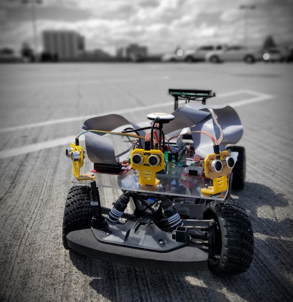
| + | Ultrasonic and Geo Sensor Based Self-Navigating Autonomous Car using CAN communication bus. | ||
| + | |||
| + | [[File:CMPE243 S19 LF main Car.jpeg|center|581px]] | ||
== Abstract == | == Abstract == | ||
| − | '''LightFury''' is an autonomous electric car project that aims to bring different embedded system paradigms together and consolidate them with industry level sophistication and robustness. This project will feature an RC car which will employ different sensors and motors to navigate the track without human assistance. Every sensor | + | '''LightFury''' is an autonomous electric car project that aims to bring different embedded system paradigms together and consolidate them with industry level sophistication and robustness. This project will feature an RC car which will employ different sensors and motors to navigate the track without human assistance. Every sensor and motor combined with a dedicated functionality is managed and processed by a controller. Such different controllers will communicate with the master node using the CAN bus protocol. Real time interaction with the car for communicating destination and getting car updates is possible with bridge controller and mobile application. The autonomous car navigation is a result of all electronic module functioning harmoniously to reach the destination location. |
| + | |||
| + | The navigation is based on destination position and car position. The autonomous car navigates with the help of GPS and compass along the checkpoints. Also, upon detecting obstacle, the car effectively navigates away from obstacle coming into its path. The motor controller effectively controls speed at turning and on ramp. Using the communication bridge and on board LED indicators we can have interpretation of the controller decisions. Also, the CAN bus communication can be used to observe the messages and sensor output on GUI or graphs. Thus we can observe the navigation decisions taken by the autonomous car. | ||
=== Introduction === | === Introduction === | ||
| Line 11: | Line 16: | ||
* Master Controller | * Master Controller | ||
* Motor Controller | * Motor Controller | ||
| − | * Sensor Controller | + | * Ultrasonic Sensor Controller |
* GPS Controller | * GPS Controller | ||
* Android application and Bluetooth Connectivity | * Android application and Bluetooth Connectivity | ||
| − | * Hardware (PCB designing) | + | * Hardware (PCB designing and Electronic layout) |
| − | * Testing | + | * Testing and Verification |
| + | |||
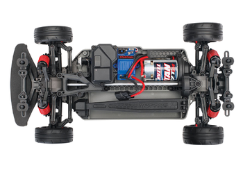
| + | The system has five SJOne Boards that run FreeRTOS and communicate with CAN bus. The car uses low power source for Boards and Sensory Units and high power source for Motor Driving Unit. The LEDs on each board are used to indicate status of controllers. The system is mounted and arranged on Traxis chassis. The final autonomous car is functional and compact unit. | ||
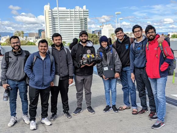
=== Team Members & Responsibilities === | === Team Members & Responsibilities === | ||
| − | + | [[File:CMPE 243 S19 LF Team.jpeg|right|581px]] | |
Project Link: <font color = blue>[https://gitlab.com/BPradnya/light-fury Gitlab Link]</font> | Project Link: <font color = blue>[https://gitlab.com/BPradnya/light-fury Gitlab Link]</font> | ||
| Line 27: | Line 34: | ||
** [https://www.linkedin.com/in/pritam-gholap/ Pritam Gholap] | ** [https://www.linkedin.com/in/pritam-gholap/ Pritam Gholap] | ||
| − | * [http://socialledge.com/sjsu/index.php/S19:_Lightfury#Sensor_ECU <font color=Maroon> | + | * [http://socialledge.com/sjsu/index.php/S19:_Lightfury#Sensor_ECU <font color=Maroon><B>Sensors</B></font>] |
** '''Ultrasonic''' | ** '''Ultrasonic''' | ||
*** [https://www.linkedin.com/in/pritam-gholap/ Pritam Gholap] | *** [https://www.linkedin.com/in/pritam-gholap/ Pritam Gholap] | ||
| − | |||
** '''Compass''' | ** '''Compass''' | ||
*** [https://www.linkedin.com/in/pradnya-bhangle/ Pradnya Bhangle] | *** [https://www.linkedin.com/in/pradnya-bhangle/ Pradnya Bhangle] | ||
*** [https://www.linkedin.com/in/akshay-ghodke-4aa4a3131/ Akshay Ghodke] | *** [https://www.linkedin.com/in/akshay-ghodke-4aa4a3131/ Akshay Ghodke] | ||
| + | ** '''RPM Sensor''' | ||
| + | *** [https://www.linkedin.com/in/niraj-surati/ Niraj Surati] | ||
| − | * [http://socialledge.com/sjsu/index.php/S19:_Lightfury#Motor_ECU <font color=purple><B>Motor Controller </B></font>] | + | * [http://socialledge.com/sjsu/index.php/S19:_Lightfury#Motor_ECU<font color=purple><B>Motor Controller & LCD </B></font>] |
** [https://www.linkedin.com/in/gaurav12yadav/ Gaurav Yadav] | ** [https://www.linkedin.com/in/gaurav12yadav/ Gaurav Yadav] | ||
** [https://www.linkedin.com/in/niraj-surati/ Niraj Surati] | ** [https://www.linkedin.com/in/niraj-surati/ Niraj Surati] | ||
| Line 44: | Line 52: | ||
** [https://www.linkedin.com/in/siddharth-chawla/ Siddharth Chawla] | ** [https://www.linkedin.com/in/siddharth-chawla/ Siddharth Chawla] | ||
| − | * [http://socialledge.com/sjsu/index.php/S19:_Lightfury#Communication_Bridge_Controller_.26_LCD <font color=Red><B>Communication Bridge Controller | + | * [http://socialledge.com/sjsu/index.php/S19:_Lightfury#Communication_Bridge_Controller_.26_LCD <font color=Red><B>Communication Bridge Controller</B></font>] |
** [https://www.linkedin.com/in/kaustubh-jawalekar-03958b106/ Kaustubh Jawalekar] | ** [https://www.linkedin.com/in/kaustubh-jawalekar-03958b106/ Kaustubh Jawalekar] | ||
** [https://www.linkedin.com/in/siddharth-chawla/ Siddharth Chawla] | ** [https://www.linkedin.com/in/siddharth-chawla/ Siddharth Chawla] | ||
| Line 123: | Line 131: | ||
| 03/19/2019 | | 03/19/2019 | ||
| | | | ||
| − | * Sensor: Perused the datasheet to get started with development | + | * <font color=Maroon>Sensor: Perused the datasheet to get started with development</font> |
| − | * GPS: Went through the datasheet and circuitry details for GPS module(no.) | + | * <font color=blue>GPS: Went through the datasheet and circuitry details for GPS module(no.)</font> |
| − | * Compass & LCD: Read the respective datasheets and manuals | + | * <font color=Maroon>Compass & LCD: Read the respective datasheets and manuals</font> |
| − | * Motor: Getting hold of the specification and the user manuals | + | * <font color=purple>Motor: Getting hold of the specification and the user manuals</font> |
| − | * Android: Design the basic template of the Application | + | * <font color=Green>Android: Design the basic template of the Application</font> |
| − | * BLE: Thorough understanding of the module | + | * <font color=Red>BLE: Thorough understanding of the module</font> |
| <font color = green><B>Completed </B></font> | | <font color = green><B>Completed </B></font> | ||
| Line 136: | Line 144: | ||
| 03/26/2019 | | 03/26/2019 | ||
| | | | ||
| − | * Sensor: Successful interfaced ultrasonic with LPC to get raw data | + | * <font color=Maroon>Sensor: Successful interfaced ultrasonic with LPC to get raw data</font> |
| − | * GPS & Compass: Acquire data from GPS and Compass | + | * <font color=blue>GPS & Compass: Acquire data from GPS and Compass</font> |
| − | * Motor: Basic motor controlled vehicle orientation | + | * <font color=purple>Motor: Basic motor controlled vehicle orientation</font> |
| − | * Android: | + | * <font color=Green>Android: Working code for scanning and connecting with a BLE standard chip</font> |
* Unit-testing for each module | * Unit-testing for each module | ||
| <font color = green><B>Completed </B></font> | | <font color = green><B>Completed </B></font> | ||
| Line 158: | Line 166: | ||
| 04/09/2019 | | 04/09/2019 | ||
| | | | ||
| − | * Sensor: Parsed the raw data to achieve useful data | + | * <font color=Maroon>Sensor: Parsed the raw data to achieve useful data</font> |
| − | * GPS & Compass: Parsing of raw data to get meaningful values | + | * <font color=blue>GPS & Compass: Parsing of raw data to get meaningful values</font> |
| − | * Motor: Take motor feedback through encoder and speed control on ramp | + | * <font color=purple>Motor: Take motor feedback through encoder and speed control on ramp</font> |
| − | * Android: Basic Android app | + | * <font color=Green>Android: Basic Android app working with the new Bluetooth SPP module </font> |
| − | * BLE: Bridge to receive Driver Heartbeat | + | * <font color=Red>BLE: Bridge to receive Driver Heartbeat</font> |
| <font color = green><B>Completed </B></font> | | <font color = green><B>Completed </B></font> | ||
| Line 172: | Line 180: | ||
| 04/16/2019 | | 04/16/2019 | ||
| | | | ||
| − | * Sensor: Design mounts and stabilize sensor input | + | * <font color=Maroon>Sensor: Design mounts and stabilize sensor input</font> |
| − | * GPS & Compass: Acquire GPS coordinate after GPS lock, Compass calliberation | + | * <font color=blue>GPS & Compass: Acquire GPS coordinate after GPS lock, Compass calliberation</font> |
| − | * Motor: Speed control and angle control precision testing | + | * <font color=purple>Motor: Speed control and angle control precision testing</font> |
| − | * Android: Develop | + | * <font color=Green>Android: Develop receiving logic and user interface for data display</font> |
| − | * BLE: Interfacing bridge to Android app | + | * <font color=Red>BLE: Interfacing bridge to Android app</font> |
| − | * PCB designing | + | * <font color=pink>PCB designing</font> |
| <font color = green><B>Completed </B></font> | | <font color = green><B>Completed </B></font> | ||
| Line 186: | Line 194: | ||
| 04/23/2019 | | 04/23/2019 | ||
| | | | ||
| − | * Sensor: Analysis for jitters in sensor value | + | * <font color=Maroon>Sensor: Analysis for jitters in sensor value</font> |
| − | * GPS & Compass: Range and bearing calculation | + | * <font color=Black>Obstacle avoidance logic on Master Controller |
| − | * Motor: Implemented LCD to display motor parameters | + | * <font color=blue>GPS & Compass: Range and bearing calculation</font> |
| − | * Android: | + | * <font color=purple>Motor: Implemented LCD to display motor parameters</font> |
| − | * BLE: Send checkpoints to GeoSensors | + | * <font color=Green>Android: Added Maps activity and sending destination button</font> |
| + | * <font color=Red>BLE: Send checkpoints to GeoSensors</font> | ||
* Master: Testing Sensor Obstacle Distance Limits | * Master: Testing Sensor Obstacle Distance Limits | ||
| − | * PCB Designing | + | * <font color=pink>PCB Designing</font> |
| <font color = green><B>Completed </B></font> | | <font color = green><B>Completed </B></font> | ||
| Line 201: | Line 210: | ||
| 04/23/2019 | | 04/23/2019 | ||
| | | | ||
| − | * Integration testing with obstacle avoidance | + | * <font color=Black>Add Geo Navigation logic on Master Controller |
| − | * Order designed PCB | + | * <font color=Maroon>Integration testing with obstacle avoidance</font> |
| + | * <font color=pink>Order designed PCB</font> | ||
| <font color = green><B>Completed </B></font> | | <font color = green><B>Completed </B></font> | ||
| Line 211: | Line 221: | ||
| 04/30/2019 | | 04/30/2019 | ||
| | | | ||
| − | * Outdoor testing and GPS navigation | + | * <font color=blue>Outdoor testing and GPS navigation</font> |
| <font color = green><B>Completed </B></font> | | <font color = green><B>Completed </B></font> | ||
| Line 220: | Line 230: | ||
| 05/07/2019 | | 05/07/2019 | ||
| | | | ||
| − | * Outdoor testing | + | * Outdoor testing and Checkpoints tracking |
| − | | | + | | <font color = green><B>Completed </B></font> |
| 05/14/2019 | | 05/14/2019 | ||
| − | |||
| − | |||
| − | |||
| − | |||
| − | |||
| − | |||
| − | |||
| − | |||
| − | |||
|- | |- | ||
| Line 239: | Line 240: | ||
| | | | ||
* ----DEMO DAY---- | * ----DEMO DAY---- | ||
| − | | | + | | <font color = green><B>Completed </B></font> |
| 05/22/2019 | | 05/22/2019 | ||
| Line 247: | Line 248: | ||
== Parts List & Cost == | == Parts List & Cost == | ||
| + | [[File:CMPE_243_SP19_LF_Traxxis.png|right|350px]] | ||
{| class="wikitable" | {| class="wikitable" | ||
|- | |- | ||
| Line 268: | Line 270: | ||
|- | |- | ||
! scope="row"| 3 | ! scope="row"| 3 | ||
| − | | | + | | Naza GPS and compass |
| − | | [ | + | | [https://www.getfpv.com/dji-naza-m-v2-gps-compass.html NazaGPS ] |
| 1 | | 1 | ||
| − | | | + | | $34 |
|- | |- | ||
! scope="row"| 4 | ! scope="row"| 4 | ||
| − | |||
| − | |||
| − | |||
| − | |||
| − | |||
| − | |||
| LIPO Batteries + Charger | | LIPO Batteries + Charger | ||
| | | | ||
| Line 285: | Line 281: | ||
| with car package | | with car package | ||
|- | |- | ||
| − | ! scope="row"| | + | ! scope="row"| 5 |
| 7" LCD | | 7" LCD | ||
| | | | ||
| Line 291: | Line 287: | ||
| | | | ||
|- | |- | ||
| − | ! scope="row"| | + | ! scope="row"| 6 |
| RPM 6520 Traxxas | | RPM 6520 Traxxas | ||
|[https://www.amazon.com/Traxxas-6520-RPM-Sensor-long/dp/B006IRXEZM/ref=sr_1_fkmr1_1?keywords=traxxas+6250+rpm&qid=1555453332&s=gateway&sr=8-1-fkmr1 Amazon] | |[https://www.amazon.com/Traxxas-6520-RPM-Sensor-long/dp/B006IRXEZM/ref=sr_1_fkmr1_1?keywords=traxxas+6250+rpm&qid=1555453332&s=gateway&sr=8-1-fkmr1 Amazon] | ||
| Line 297: | Line 293: | ||
| $11.67 | | $11.67 | ||
|- | |- | ||
| − | ! scope="row"| | + | ! scope="row"|7 |
| − | | | + | | Parallax Ping Ultrasonic Sensor |
| − | | [https://www. | + | | [https://www.amazon.com/Parallax-Ultrasonic-Range-Sensor-28015/dp/B004SRTM0K/ref=asc_df_B004SRTM0K/?tag=hyprod-20&linkCode=df0&hvadid=312127837151&hvpos=1o1&hvnetw=g&hvrand=11113507837975239347&hvpone=&hvptwo=&hvqmt=&hvdev=c&hvdvcmdl=&hvlocint=&hvlocphy=9032166&hvtargid=pla-568526044446&psc=1&tag=&ref=&adgrpid=57636291530&hvpone=&hvptwo=&hvadid=312127837151&hvpos=1o1&hvnetw=g&hvrand=11113507837975239347&hvqmt=&hvdev=c&hvdvcmdl=&hvlocint=&hvlocphy=9032166&hvtargid=pla-568526044446 Parallax ping] |
| 4 | | 4 | ||
| $150 | | $150 | ||
| + | |- | ||
| + | ! scope="row"| 8 | ||
| + | | Sensor Mounts | ||
| + | |[https://www.amazon.com/HC-SR04-Ultrasonic-Distance-Measuring-Transducer/dp/B01N0G8BCV/ref=sr_1_7?crid=3LDNRIW3H50NE&keywords=ultrasonic+sensor+mounting+bracket&qid=1558658522&s=electronics&sprefix=ultrasonic+sensor+m%2Celectronics%2C180&sr=1-7 Sensor Mounts] | ||
| + | |4 | ||
| + | | $11.96 | ||
|- | |- | ||
! scope="row"| 9 | ! scope="row"| 9 | ||
| Line 307: | Line 309: | ||
|[https://www.pcbway.com/ PCBWay] | |[https://www.pcbway.com/ PCBWay] | ||
|1 | |1 | ||
| − | | $ | + | | $30.00 |
| + | |- | ||
| + | ! scope="row"| 10 | ||
| + | | SJOne board | ||
| + | | | ||
| + | | 5 | ||
| + | | From Preet | ||
|- | |- | ||
|} | |} | ||
| + | == DBC File == | ||
| + | <pre> | ||
| + | VERSION "" | ||
| + | |||
| + | NS_ : | ||
| + | BA_ | ||
| + | BA_DEF_ | ||
| + | BA_DEF_DEF_ | ||
| + | BA_DEF_DEF_REL_ | ||
| + | BA_DEF_REL_ | ||
| + | BA_DEF_SGTYPE_ | ||
| + | BA_REL_ | ||
| + | BA_SGTYPE_ | ||
| + | BO_TX_BU_ | ||
| + | BU_BO_REL_ | ||
| + | BU_EV_REL_ | ||
| + | BU_SG_REL_ | ||
| + | CAT_ | ||
| + | CAT_DEF_ | ||
| + | CM_ | ||
| + | ENVVAR_DATA_ | ||
| + | EV_DATA_ | ||
| + | FILTER | ||
| + | NS_DESC_ | ||
| + | SGTYPE_ | ||
| + | SGTYPE_VAL_ | ||
| + | SG_MUL_VAL_ | ||
| + | SIGTYPE_VALTYPE_ | ||
| + | SIG_GROUP_ | ||
| + | SIG_TYPE_REF_ | ||
| + | SIG_VALTYPE_ | ||
| + | VAL_ | ||
| + | VAL_TABLE_ | ||
| + | |||
| + | BS_: | ||
| + | |||
| + | BU_: DBG DRIVER IO MOTOR SENSOR LF_SENSOR LF_MOTOR LF_DRIVER LF_GEO LF_BRIDGE LF_DEBUG_NODE | ||
| + | |||
| + | BO_ 10 LF_BRIDGE_START_STOP: 1 LF_BRIDGE | ||
| + | SG_ start_stop_flag : 0|2@1+ (1,0) [0|0] "ON/OFF" LF_DRIVER,LF_DEBUG_NODE | ||
| + | |||
| + | BO_ 11 LF_bridge_dest: 8 LF_BRIDGE | ||
| + | SG_ dest_lat : 0|32@1+ (0.000001,0) [0|0] "Degree" LF_GEO | ||
| + | SG_ dest_long : 32|32@1- (-0.000001,0) [0|0] "Degree" LF_GEO | ||
| + | |||
| + | BO_ 51 LF_SENSOR_HB: 1 LF_SENSOR | ||
| + | SG_ sensor_hb : 0|1@1+ (1,0) [0|0] "HB" LF_DRIVER | ||
| + | |||
| + | BO_ 52 LF_MOTOR_HB: 1 LF_MOTOR | ||
| + | SG_ motor_hb : 0|1@1+ (1,0) [0|0] "HB" LF_DRIVER | ||
| + | |||
| + | BO_ 53 LF_GEO_HB: 1 LF_GEO | ||
| + | SG_ geo_hb : 0|1@1+ (1,0) [0|0] "HB" LF_DRIVER | ||
| + | |||
| + | BO_ 54 LF_BRIDGE_HB: 1 LF_BRIDGE | ||
| + | SG_ bridge_hb : 0|1@1+ (1,0) [0|0] "HB" LF_DRIVER | ||
| + | |||
| + | BO_ 55 LF_DRIVER_HB: 1 LF_DRIVER | ||
| + | SG_ driver_hb : 0|1@1+ (1,0) [0|0] "HB" LF_SENSOR,LF_MOTOR,LF_GEO,LF_BRIDGE | ||
| + | |||
| + | BO_ 80 LF_SENSOR_DATA: 5 LF_SENSOR | ||
| + | SG_ left_sensor : 0|8@1+ (1,0) [0|0] "Centimeters" LF_DRIVER,LF_BRIDGE | ||
| + | SG_ front_sensor : 8|8@1+ (1,0) [0|0] "Centimeters" LF_DRIVER,LF_BRIDGE | ||
| + | SG_ right_sensor : 16|8@1+ (1,0) [0|0] "Centimeters" LF_DRIVER,LF_BRIDGE | ||
| + | SG_ rear_sensor : 24|8@1+ (1,0) [0|0] "Centimeters" LF_DRIVER,LF_BRIDGE | ||
| + | |||
| + | BO_ 81 LF_MOTOR_CMD: 1 LF_DRIVER | ||
| + | SG_ MOTOR_CMD_drive_enum : 0|4@1+ (1,0) [0|0] "" LF_MOTOR | ||
| + | SG_ MOTOR_CMD_steer_enum : 4|4@1+ (1,0) [0|0] "" LF_MOTOR | ||
| + | |||
| + | BO_ 82 LF_GEO_BT_LAT_LONG: 8 LF_GEO | ||
| + | SG_ GEO_BT_lat_debug : 0|32@1+ (0.000001,0) [0|0] "Degree" LF_BRIDGE | ||
| + | SG_ GEO_BT_long_debug : 32|32@1- (-0.000001,0) [0|0] "Degree" LF_BRIDGE | ||
| + | |||
| + | BO_ 83 LF_GEO_BT_COMP: 6 LF_GEO | ||
| + | SG_ GEO_BT_comp_debug : 0|10@1+ (1,0) [0|0] "Degree" LF_BRIDGE,LF_DEBUG_NODE | ||
| + | SG_ GPS_FIX : 10|3@1+ (1,0) [0|0] "" LF_BRIDGE,LF_DEBUG_NODE | ||
| + | SG_ GPS_LOCK : 13|1@1+ (1,0) [0|0] "" LF_BRIDGE,LF_DEBUG_NODE | ||
| + | SG_ GEO_BT_turning_angle_debug : 14|10@1- (-1,0) [0|0] "" LF_BRIDGE,LF_MOTOR,LF_DEBUG_NODE | ||
| + | SG_ CURRENT_CHECKPOINT : 24|8@1+ (1,0) [0|0] "" LF_BRIDGE,LF_MOTOR,LF_DEBUG_NODE | ||
| + | SG_ CURRENT_RADIUS : 32|16@1+ (0.01,0) [0|0] "Meters" LF_BRIDGE,LF_MOTOR,LF_DEBUG_NODE | ||
| + | |||
| + | BO_ 84 LF_GEO_DATA: 2 LF_GEO | ||
| + | SG_ direction_geo : 0|3@1+ (1,0) [0|1] "GeoDirection" LF_DRIVER | ||
| + | SG_ magnitude_geo : 3|8@1+ (1,0) [0|180] "Degree" LF_DRIVER | ||
| + | |||
| + | BO_ 85 LF_CHECKPOINT_BT_LAT_LONG: 8 LF_GEO | ||
| + | SG_ CHECKPOINT_BT_lat_debug : 0|32@1+ (0.000001,0) [0|0] "Degree" LF_BRIDGE,LF_DEBUG_NODE | ||
| + | SG_ CHECKPOINT_BT_long_debug : 32|32@1- (-0.000001,0) [0|0] "Degree" LF_BRIDGE,LF_DEBUG_NODE | ||
| + | |||
| + | BO_ 600 LF_GEO_CAN_DEBUG_MSG: 3 LF_GEO | ||
| + | SG_ GEO_DEBUG_lat : 0|8@1+ (1,0) [0|0] "Degree" LF_DEBUG_NODE | ||
| + | SG_ GEO_DEBUG_long : 8|8@1+ (1,0) [0|0] "Degree" LF_DEBUG_NODE | ||
| + | SG_ GEO_DEBUG_comp : 16|8@1+ (1,0) [0|0] "Degree" LF_DEBUG_NODE | ||
| + | |||
| + | BO_ 601 LF_MOTOR_CAN_DEBUG_MSG: 7 LF_MOTOR | ||
| + | SG_ Duty_cycle : 0|16@1+ (0.1,0) [0|0] "Percent" LF_DEBUG_NODE,LF_BRIDGE | ||
| + | SG_ TargetSpeed : 16|16@1+ (0.1,0) [0|0] "MpH" LF_DEBUG_NODE,LF_BRIDGE | ||
| + | SG_ car_mph : 32|16@1+ (0.1,0) [0|0] "MpH" LF_DEBUG_NODE,LF_BRIDGE | ||
| + | SG_ axle_rps : 48|8@1+ (1,0) [0|0] "Rot/S" LF_DEBUG_NODE,LF_BRIDGE | ||
| + | |||
| + | BA_ "FieldType" SG_ 81 MOTOR_CMD_drive_enum "MOTOR_CMD_drive_enum"; | ||
| + | BA_ "FieldType" SG_ 81 MOTOR_CMD_steer_enum "MOTOR_CMD_steer_enum"; | ||
| + | |||
| + | VAL_ 81 MOTOR_CMD_drive_enum 1 "drive_forward" 2 "drive_moderate" 3 "drive_slow" 4 "drive_stop" 5 "drive_reverse"; | ||
| + | VAL_ 81 MOTOR_CMD_steer_enum 1 "steer_front" 2 "steer_soft_left" 3 "steer_moderate_left" 4 "steer_soft_right" 5 "steer_moderate_right"; | ||
| + | |||
| + | |||
| + | </pre> | ||
| + | |||
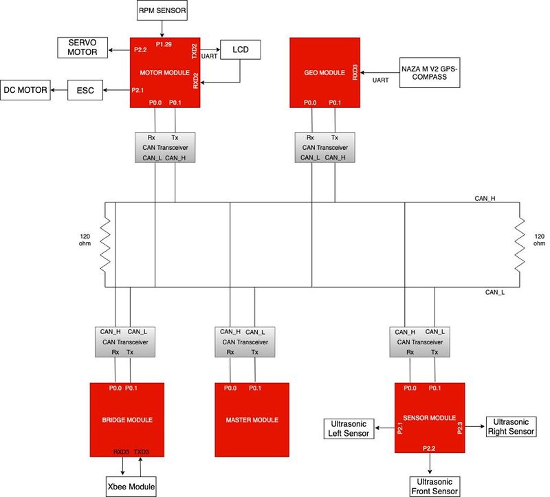
| + | == System Architecture == | ||
| + | |||
| + | [[File:CMPE 243 S19 LF Sys Arch.jpeg|center|800px|'''PCB Schematic]] | ||
== Printed Circuit Board == | == Printed Circuit Board == | ||
| + | |||
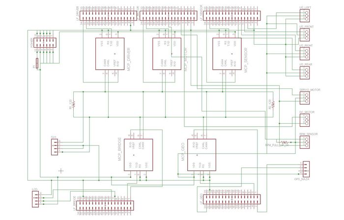
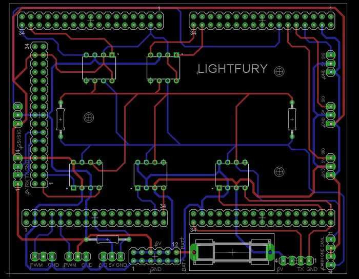
Initial prototyping was done on wire wrapping board for a common CAN bus and power input to all the controllers. Over time on finalizing the layout and components, we designed a PCB to have a compact and stable connections for our electronic and mechanical components. | Initial prototyping was done on wire wrapping board for a common CAN bus and power input to all the controllers. Over time on finalizing the layout and components, we designed a PCB to have a compact and stable connections for our electronic and mechanical components. | ||
| − | Planned a single PCB to place and route CAN transceivers and eliminate dangling wires. | + | Planned a single PCB to place and route CAN transceivers and eliminate dangling wires. The PCB was designed with Eagle CAD software tool. Components were placed on the design after careful consideration for compactness and routing constraints. The design was modified multiple time to cater for new requirement. Finally, the designed PCB was placed on the chassis for stable and compact car design. |
| + | [[File:CMPE_243_S19_PCB_Schematic.jpg|center|700px|'''PCB Schematic]] | ||
| + | [[File:CMPE_243_S19_PCB_design.jpg|center|700px|'''PCB Layout]] | ||
| − | |||
| − | |||
| − | < | + | <BR/> |
== CAN Communication == | == CAN Communication == | ||
| − | |||
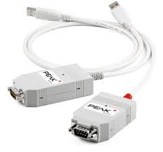
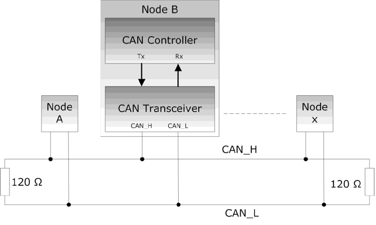
| − | + | Controlled Area Network or CAN is broadcast bus used in modern autonomous car systems for reliably communicating between devices. Here we use CAN bus to communicate between different controllers and debug with CAN messages. An errorneous node goes in bus off mode and other node keep communicating over CAN bus. This is why CAN is preferred over other communication protocols. Using PCAN dongle we can debug CAN communication on the bus in real time. These messages have helped in developing the navigation algorithm after observing the system in real time and monitoring CAN communication channel. | |
| − | + | ||
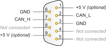
| + | The CAN Bus physical design and communication is described in this section. The CAN controller present over SJOne board communicates to external transceiver over Rx and Tx. CAN transceiver transmit the message to CAN bus using differential signals. 0 is the dominant bit. This means that message with lower CAN message ID wins the bus arbitration and transmits its message on the bus. The other transceiver stops transmitting and waits for the next clock cycle to begin arbitration. Hence CAN message ID also acts as priority indicator. This arrangement is terminated with 2 terminal resistors of 120 Ohm. This removes signal reflection from the node end for combating echo from the signal. Due to differential means of transmitting the signal, the CAN bus is immune to noise loss and interference. All transceivers receive the CAN message. Only the intended terminal decodes the message. In case the message is not received by the terminal it goes into MIA state and consequent action can be decided by the user. This makes CAN convenient to be used in any applications. | ||
| + | |||
| + | The CAN follows certain data formatting method known as DBC. With the help of CAN transceivers, each sensor module sends data in DBC format to the controller. The data from ultrasonic sensor helps in obstacle detection. The GPS and Compass Module helps with navigation. The LCD gives live information of component status and values. Finally there is motors and control unit for navigating the car as per the commands from controller. All this controllers share information over CAN bus. | ||
| + | |||
| + | The CAN DBC file is unique format for information storage into structure and recording sender and receiver of the CAN network. It include the different message IDs along with message format and scale offset operations if any. Also there can be debugging node which keeps note of all the node data and can be used to observe the CAN communication. The DBC file comes handy while observing CAN operations in action with the help of Peak CAN. This became really helpful while observing sensor values in graph to detect false triggering. | ||
| + | |||
| + | [[File:CMPE_243_S19_LF_PeakCAN.jpg|frame|right|200px|PeakCAN dongle]][[File:CMPE_243_S19_LF_PCANconnections.png|frame|right|200px|Can DB9 connections]] | ||
| + | [[File:CMPE_243_S19_LF_CAN_HW.png|frame|center|300px|CAN Hardware]] | ||
=== DBC File === | === DBC File === | ||
| Line 338: | Line 467: | ||
== Sensor ECU == | == Sensor ECU == | ||
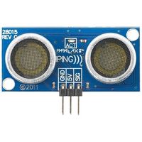
| − | + | [[File:CMPE_243_S19_UltrasonicSensor.jpg|thumb|right|200px|Parallax Ultrasonic Sensor]] | |
The sensor ECU is consist of SJOne board interfaced with four Parallax ping ultrasonic sensors. The primary objective of sensor ECU is to detect the obstacles and provide the corresponding information to the master controller in order to avoid those obstacles. According to beam angles, each sensor is mounted in such a way that the car can avoid the obstacles present in front and rear of the car. Based on the acquired information from sensors, distance is calculated and forwarded to the master controller over CAN bus. Based on the previous project reports, Parallax ping sensors were decided for this project as they provided reliable outputs with better range. | The sensor ECU is consist of SJOne board interfaced with four Parallax ping ultrasonic sensors. The primary objective of sensor ECU is to detect the obstacles and provide the corresponding information to the master controller in order to avoid those obstacles. According to beam angles, each sensor is mounted in such a way that the car can avoid the obstacles present in front and rear of the car. Based on the acquired information from sensors, distance is calculated and forwarded to the master controller over CAN bus. Based on the previous project reports, Parallax ping sensors were decided for this project as they provided reliable outputs with better range. | ||
| Line 347: | Line 476: | ||
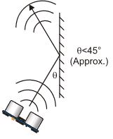
*Obstacle with the reflective surface will reflect sound at a shallow angle ( < 45 degrees), which won't be reflected back towards the sensor | *Obstacle with the reflective surface will reflect sound at a shallow angle ( < 45 degrees), which won't be reflected back towards the sensor | ||
*The sound pulse gets reflected off the floor when the sensor is mounted low on the device | *The sound pulse gets reflected off the floor when the sensor is mounted low on the device | ||
| + | |||
| + | |||
| + | <table> | ||
| + | <tr> | ||
| + | <td> | ||
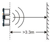
| + | <li style="display: inline-block;"> [[File:Cmpe243_S19_LF_sensor_1.jpg|left|300px|thumb|Distance greater than 3 m]] </li> | ||
| + | </td> | ||
| + | <td> | ||
| + | </td> | ||
| + | <td> | ||
| + | <li style="display: inline-block;"> [[File:Cmpe243_S19_LF_sensor_2.jpg|left|300px|thumb|Shallow angle ( < 45 degrees) reflection]] </li> | ||
| + | </td> | ||
| + | <td> | ||
| + | </td> | ||
| + | <td> | ||
| + | <li style="display: inline-block;"> [[File:Cmpe243_S19_LF_sensor_3.jpg|right|900px|thumb|Unable to detect small object]] </li> | ||
| + | </td> | ||
| + | </tr> | ||
| + | </table> | ||
=== Hardware Design === | === Hardware Design === | ||
| Line 359: | Line 507: | ||
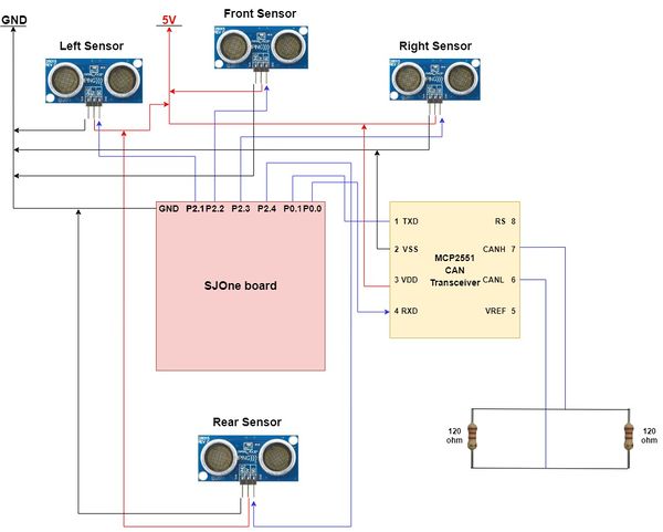
#Pin 0.1 of SJOne board is configured as TD1 and is connected to TXD pin (Pin 1) of MCP 2551 (can transceiver). | #Pin 0.1 of SJOne board is configured as TD1 and is connected to TXD pin (Pin 1) of MCP 2551 (can transceiver). | ||
| − | |||
| − | |||
| − | + | <center> | |
| + | <table> | ||
| + | <tr> | ||
| + | <td> | ||
| + | <li style="display: inline-block;"> [[File:Cmpe243_S19_LF_sensor_HW.jpg|600px|thumb|Sensor Hardware Interface]] </li> | ||
| + | </td> | ||
| + | </tr> | ||
| + | </table> | ||
| + | </center> | ||
| + | === Software Design === | ||
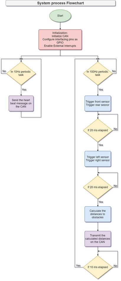
| + | [[File:CMPE_243_S19_Sensor_ECU_SW_flowchart.jpg|right|thumb|Sensor ECU SW flowchart|410px]] | ||
| + | Sensor triggering is implemented in the 100Hz periodic task. Sensors are triggered in sets instead of all the sensors triggering at the same time. This technique helped in minimizing signal interference between two adjoining sensors. The front and back sensors are triggered first and then the left and right sensors. Each sensor is fed with a 5us high pulse from the host controller and it emits a short ultrasonic burst and then starts listening for the echo. After sending out the pulse, the SIG pin becomes high and it goes low when the obstacle is detected. To sense this pulse, external interrupts are enabled. The maximum duration of this pulse is 18.5ms which denotes that there is no obstacle in front of the sensor. Given this time period, left and right sensors are triggered 20ms after front and back sensors are triggered. Each sensor is triggered at 20Hz, i.e., after 50ms. | ||
| + | After collecting the data from sensors, distance is calculated and it is transmitted over CAN bus. CAN transmission also takes place 100Hz task only so that updated values are sent at the faster speed. A heartbeat message is sent to the master controller indicating that the sensor controller is up and running. This message is sent using 10Hz periodic task. | ||
| − | + | === Implementation === | |
| − | |||
#Initialize the CAN bus either on can1 or can2 with baud rate of 100 kbps and RX/TX queues of size 100 | #Initialize the CAN bus either on can1 or can2 with baud rate of 100 kbps and RX/TX queues of size 100 | ||
#Configure the host controller pins 2.1, 2.2, 2.3 and 2.4 as GPIO pins (These pins are connected to SIG pin of left, front, right and rear sensor respectively) | #Configure the host controller pins 2.1, 2.2, 2.3 and 2.4 as GPIO pins (These pins are connected to SIG pin of left, front, right and rear sensor respectively) | ||
| Line 384: | Line 541: | ||
#Fetch the system uptime when falling edge interrupt occurs. The noted time can be considered as the "stop_time" of the echo pulse. | #Fetch the system uptime when falling edge interrupt occurs. The noted time can be considered as the "stop_time" of the echo pulse. | ||
#Calculate the distance from the obstacle. (Distance = ((start_time - stop_time)/147) in inches or Distance = ((start_time - stop_time)/57.14) in cm). | #Calculate the distance from the obstacle. (Distance = ((start_time - stop_time)/147) in inches or Distance = ((start_time - stop_time)/57.14) in cm). | ||
| + | #Send the calculated distance to the master controller over the CAN bus. | ||
| + | Steps 4 to 10 are executed within the 100Hz periodic task. | ||
=== Technical Challenges === | === Technical Challenges === | ||
| Line 415: | Line 574: | ||
== Motor ECU == | == Motor ECU == | ||
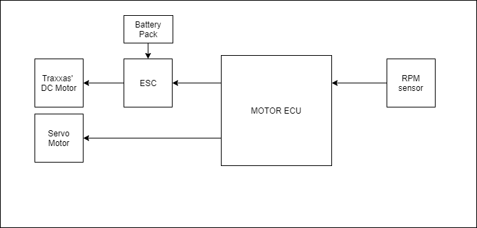
| + | The motor controller is responsible for controlling the steering, direction of rotation ( forward, stop or reverse) and maintaining speed of the car. Additionally the Motor ECU also shelters an LCD to display parameters that are relevant for debugging certain features. It controls steering at different angles with the help of a servo motor. Rotation of the DC motor and speed is controlled by the ESC (Electronic Speed Controller). Different components that are in scope of Motor ECU: | ||
| + | * ESC | ||
| + | * DC Motor | ||
| + | * Servo Motor | ||
| + | * RPM Sensor (Hall Effect Sensor) | ||
| + | * LCD Module | ||
| + | |||
| + | [[File:CMPE_243_S19_MotorECU_Block.png|800px|thumb|center| '''Block Diagram of Motor ECU''']] | ||
| + | |||
| + | |||
| + | === Prerequisites === | ||
| + | |||
| + | ==== [https://traxxas.com/support/Programming-Your-Traxxas-Electronic-Speed-Control '''Getting Started with ESC'''] ==== | ||
| + | |||
| + | Before you begin calibration of a Traxxas ESC, please check the traxxas ESC datasheet and select appropriate profile: | ||
| + | *Sport Mode : 100% Forward, 100% Brakes, 100% Reverse | ||
| + | *Race Mode : 100% Forward, 100% Brakes, No Reverse | ||
| + | *Training Mode: 50% Forward, 100% Brakes, 50% Reverse | ||
| + | |||
| + | If you configure your ESC in Racing Mode, it will not respond to reverse signals. | ||
| + | |||
| + | To select the Sports Profile: | ||
| + | * Connect a fully charged battery pack to the ESC and turn on your transmitter. | ||
| + | * With the ESC off, press and hold the EZ-Set button until the LED turns solid green, then solid red and then begins blinking red (indicating the Profile numbers). | ||
| + | *When the LED blinks red once, release the EZ-Set button. | ||
| + | |||
| + | ==== [https://traxxas.com/support/Programming-Your-Traxxas-Electronic-Speed-Control '''Calibrating ESC'''] ==== | ||
| + | |||
| + | ESC takes an PWM wave as input and controls direction and speed of the motor. In order for the ESC to repsond to PWM signals from SJone board, it needs to be calibrated. | ||
| + | |||
| + | * To move the motor speed forward in full throttle ('''100 % forward''') the ESC requires a high pulse of """2 ms""". | ||
| + | * To """stop""" the motor a PWM pulse with on-time of '''1.5 ms''' is required by the ESC. | ||
| + | * To move motor full-throttle backwards ('''100% backward''') pulse of on-time """1 ms""" is required. | ||
| + | |||
| + | The PWM can be any frequency as long as above on-time condition is satisfied. | ||
| + | |||
| + | Example: For our project, we chose a 50 Hz frequency PWM wave for ESC as well as Servo. | ||
| + | A 50 Hz frequency wave has 20 ms period. So get on-time of 1.5 ms, duty cycle needs to be 7.5%. | ||
| + | *100% Forward - 2 ms - 10% duty cycle. | ||
| + | *Stop/Neutral - 1.5 ms - 7.5% duty cycle. | ||
| + | *100% Backward - 1 ms - 5% duty cycle. | ||
| + | |||
| + | |||
| + | ===== Steps to calibrate ESC ===== | ||
| + | *Connect a fully charged battery pack to the ESC. | ||
| + | |||
| + | *Generate PWM for stop/neutral position. | ||
| + | |||
| + | *Press and hold the EZ-Set button. The LED will first turn green and then red. Release the EZ-Set button. | ||
| + | |||
| + | *When the LED blinks RED ONCE, generate PWM to the full throttle position (100% forward) and hold it there. | ||
| + | |||
| + | *When the LED blinks RED TWICE, generate PWM to the full reverse and hold it there. | ||
| − | + | *When the LED blinks GREEN ONCE, programming is complete. The LED will then shine green or red indicating the ESC is on and at neutral. | |
=== Hardware Design === | === Hardware Design === | ||
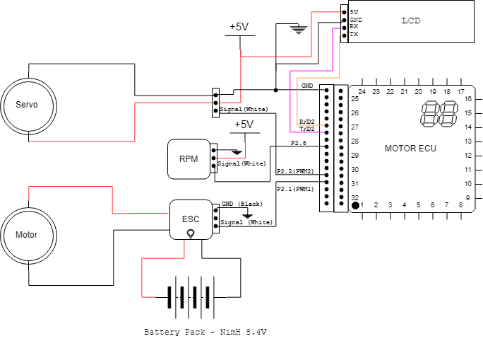
| − | The traxxas chassis came with ECU and servo controller. It has DC motor with servo control for turning. Working on 3.4 V/ 3000mAH power specifications it has axle to rotate all the four wheels. The feedback for PWM controlled speed attained is fed back through magnetic encoder. The front wheels have servo connection for turning. The chassis is placed on suspension unit for shock absorbing. An acrylic sheet is mounted over certain height on which the PCB and controller is placed. The motor controller sends signals for | + | The traxxas chassis came with ECU and servo controller. It has DC motor with servo control for turning. Working on 3.4 V/ 3000mAH power specifications it has axle to rotate all the four wheels. The feedback for PWM controlled speed attained is fed back through magnetic encoder. The front wheels have servo connection for turning. The chassis is placed on suspension unit for shock absorbing. An acrylic sheet is mounted over certain height on which the PCB and controller is placed. The motor controller PWM sends signals for DC motor and servo motor angles for driving the car. |
| + | |||
| + | [[File:CMPE 243 S19 LF motor HW2.png|800px|thumb|center| '''Hardware Design Motor ECU''']] | ||
| + | |||
| + | ==== RPM Sensor ==== | ||
=== Software Design === | === Software Design === | ||
| Line 447: | Line 663: | ||
== Geographical Controller == | == Geographical Controller == | ||
| + | [[File:CMPE_243_SP19_LF_NAZA.jpg| 200px|right|thumb|NAZA GPS and Compass module]] | ||
| + | The GPS module provides the location of the car on the earth in terms of latitude and longitude in degrees. This helps us know the current position of the car to navigate to the destination. We use this information to calculate range and bearing of the car to the destination and navigate according to this information. The compass gives the heading of the car with respect to North direction. In case the car is facing north, we will get 0 degree in compass. However, that is not always true and repeatable, hence the compass module needs caliberation. The gps and compass module together called as geo sensors form important part of Geographical Controller. The geo sensors module used in the car is from NAZA. The positioning of the module on the car is such that it is away from all the electromagnetic interference. The NAZA module communicates to geographical controller over UART to send data. This data is decoded by the Geographical Controller and send to Master Controller for further action to the Motor Controller. The part of the LCD display mounted on the car. The Geographical Controller interprets geo data for the Master Controller. | ||
| − | + | === Hardware Design === | |
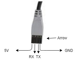
| + | The NAZA module consisting of both gps locator and compass is mounted on a stbaud rateand to avoid electromagnetic interference. The small notch on the device indicates the front direction of the compass. The module is interfaced to the SJOne board through UART at a baud rate of 115200 and called periodically in 10Hz frequency. The module is set to transmit mode hence receiver UART signal connection was used to just configure the GPS baud rate (Initially comes with 9600 ). It sends longitude and latitude (message id: 0x10) in one cycle and compass value (message id: 0x20) in the next. It also sends the version number (message id : 0x30), but it is not being used in the project. | ||
| − | = | + | The GPS module, works in all weather conditions, within an unobstructed line of sight communication using 4 or more GPS satellites. As more number of satellite in line of sight to a GPS receiver, higher is the accuracy in determining the position of the module. When a receiver receives a signal from one of the satellite, it calculates its distance from the satellite considering a 3-D sphere with the satellite located at the center of the sphere. Once the receiver receives the signal from at least three satellites out of 32, the receiver then points its location using trilateration process. The trilateration is the process of determining module position based on intersecting spheres of satellite distance to module. The GPS module calculates its distance from the satellite considering a 3-D sphere with the satellite located at the center of the sphere. Once the receiver does the same with 3 other GPS satellites, the receiver then proceeds to find the intersection point of the 3 spheres to calculate it’s location.A GPS requires at least 3 satellites to calculate 2-D position(latitude and longitude on a map) at mean sea level. However, it requires at least 4 satellites to find receivers 3-D position(latitude, longitude, and altitude) |
| + | |||
| + | |||
| + | <center> | ||
| + | <table> | ||
| + | <tr> | ||
| + | <td> | ||
| + | <li style="display: inline-block;"> [[File:Naza_Connections.jpg|600px|thumb|Geo Controller Software Implementation]] </li> | ||
| + | </td> | ||
| + | </tr> | ||
| + | </table> | ||
| + | </center> | ||
=== Software Design === | === Software Design === | ||
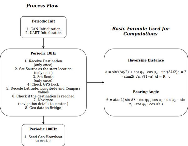
| − | < | + | '''Bearing distance calculation''': |
| + | Bearing distance is the shortest distance from point A to point B on the great-cicle of the Earth. We have used Haversine Distance formula for the same | ||
| + | |||
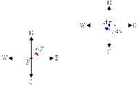
| + | '''Bearing Angle Calculation''': | ||
| + | Bearing angle is the angle representing the desired navigation of the object with respect to the north in clockwise direction. The bearing angle is used to calculate the relative angle between two points on the map. In our case we used this to calculate the turning angle which tells the car how much to turn by and which direction. | ||
| + | |||
| + | '''Route Planning''': | ||
| + | We have designed a simple algorithm takes in source and destination as a input parameter. Also we have maintained a pool of checkpoints which avoids the car to approach inaccessible locations. The algorithm calculates midpoint of the source and destination and calculates the nearest checkpoint to it. Later this checkpoint will be used as a source to calculate midpoint and searched for the nearest checkpoint. | ||
| + | |||
| + | [[File:Cmpe243 bearing angle.gif| 200px|right|thumb|NAZA GPS and Compass module]] | ||
| + | |||
| + | <center> | ||
| + | <table> | ||
| + | <tr> | ||
| + | <td> | ||
| + | <li style="display: inline-block;"> [[File:Cmpe243_GPS_Software_Implementation.jpg|600px|thumb|Geo Controller Software Implementation]] </li> | ||
| + | </td> | ||
| + | </tr> | ||
| + | </table> | ||
| + | </center> | ||
=== Technical Challenges === | === Technical Challenges === | ||
| − | |||
==== Unreliable GPS lock ==== | ==== Unreliable GPS lock ==== | ||
| − | |||
| − | |||
| + | '''''Problem Summary:''''' Was losing GPS lock necessary to get reliable GPS data. | ||
| + | |||
| + | '''''Problem Resolution:''''' Worked on the received data from the GPS module. Ensured GPS lock only upon receiving reliable and consistent geo data. | ||
| + | |||
| + | ==== Noisy Compass Values ==== | ||
| + | '''''Problem Summary:''''' The compass would not return same value at same position on switching power off and on again. | ||
| + | |||
| + | '''''Problem Resolution:''''' Initially, we thought it was just due to electromagnetic interference. However that was not just the case and the problem also was with compass calibration. Hence, implemented Kalman filter to reduce the sudden change in compass sensor values. | ||
| + | |||
| + | '''NOTE:''' | ||
| + | # Always for testing and data calibration, do it in an open air. | ||
| + | # Before testing the car for navigation, check multiple times (on the car) if there is any offset associated with the compass. If it does and the offset is constant, just compensate the offset in the received data.# | ||
| + | # Also try including filters to avoid compass angle fluctuations. | ||
<BR/> | <BR/> | ||
| − | == Communication Bridge Controller | + | == Communication Bridge Controller == |
| − | + | ||
| + | The bridge controller is an interface of communication between car and the android Application controlling the car. Whatever commands App needs to send to the car, they are sent using Bridge Controller. All the data to be updated on the android application such as current location, car speed etc., is first sent to Bridge controller and then bridge controller sends the whole data to Android Application. Effectively, this controller communicates with each and every controller on the car and hence it is one of the crucial controllers. This controller also keeps the track of Master Controller's Heart Beat and Resets the car if master controller is not responding with heart beat. | ||
=== Hardware Design === | === Hardware Design === | ||
| − | + | ||
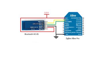
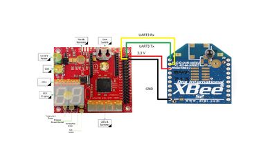
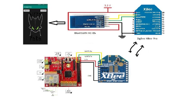
| + | Bridge controller uses XBee Pro ZigBee module to communicate with the android application. ZigBee provides long range of communication i.e. approximately up to 100 meters when in line of sight or practically around 80 meters. However, there is no method to send data directly to ZigBee module from android application. Thus, to work around, a Bluetooth module is connected with Zigbee module. In this method, app can send data to Bluetooth module placed near to it. The BT module is connected to 1 ZigBee module directly with Tx-Rx wires. Hence The data received by BT is automatically transmitted to ZigBee module 1. This XBee receives the data from BT and sends it ahead to another XBee Pro; placed on the Bridge Controller on the car. The whole process occurs in reverse when any data is to be updated on the application from car. | ||
| + | Thus, the hardware design of Bridge controller consists of 3 parts:- | ||
| + | *Bluetooth HC05 - XBee Pro Connection | ||
| + | *SJOne- XBee Pro Connection | ||
| + | *Integration for the communication | ||
| + | <center> | ||
| + | <table> | ||
| + | <tr> | ||
| + | <td> | ||
| + | <li style="display: inline-block;"> [[File:Cmpe243_S19_LF_BT_XBee_connection.jpg|370px|thumb|Bluetooth - XBee Connection]] </li> | ||
| + | </td> | ||
| + | <td> | ||
| + | <li style="display: inline-block;"> [[File:Cmpe243_S19_LF_SJOne_Xbee_Interface.jpg|400px|thumb|Bluetooth - XBee Connection]] </li> | ||
| + | </td> | ||
| + | </tr> | ||
| + | </table> | ||
| + | |||
| + | |||
| + | <table> | ||
| + | <tr> | ||
| + | <td> | ||
| + | <li style="display: inline-block;"> [[File:Cmpe243_S19_LF_Bridge_HW.jpg|700px|thumb|Bridge Hardware Interface]] </li> | ||
| + | </td> | ||
| + | </tr> | ||
| + | </table> | ||
| + | </center> | ||
=== Software Design === | === Software Design === | ||
| − | The bridge controller being the controller to communicate with all the controller on the car has to adhere to the data formats send by the respective controllers. | + | |
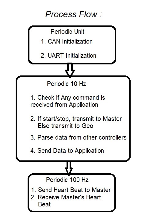
| + | The bridge controller being the controller to communicate with all the controller on the car has to adhere to the data formats send by the respective controllers. The controller should always fetch the data in different formats, parse it to convert to a single format and then send to mobile application. The process becomes reverse i.e. accept the data from application in one format and parse it to convert in different formats to send to every other controller. | ||
| + | |||
| + | The software design starts with initialization of few peripherals such as Can Bus for communication with other controllers, UART for XBee Pro module. These initializations are not periodic and hence initialized only once in Init functions. | ||
| + | |||
| + | Android Application sends 2 commands to the car using Bridge Controller:- | ||
| + | *Start/Stop the car:- This command is nothing but a 1 character command to start or stop the car manually. The car will not start driving till it receives start and destination co-ordinates from the application. However, it automatically stops after reaching the destination. The stop command is for manual stops. | ||
| + | |||
| + | *Destination of the car:- Android application gives the destination latitude and longitude coordinates in the form of comma separated string. | ||
| + | |||
| + | Both of the commands above need to be parsed in 2 different formats. | ||
| + | |||
| + | *Any of the command with single character is not Start/stop. Thus, start/Stop command validated before forwarding it to the CAN bus. It is then parsed and a boolean variable is given to master controller to start the car. | ||
| + | |||
| + | *Any command with single comma and greater than single character command is destination. This command is also validated and then transmitted to over CAN bus to Geo Controller for route determination. | ||
| + | |||
| + | These Two commands are generally not periodic and hence both of these are called in 10Hz periodic tasks. | ||
| + | |||
| + | <pre> | ||
| + | void C_period_10Hz(uint32_t count) | ||
| + | { | ||
| + | (void) count; | ||
| + | |||
| + | if(xBee_receive(cmd_over_wireless,sizeof(cmd_over_wireless),3)) | ||
| + | { | ||
| + | if(cmd_over_wireless[1] == '\0') | ||
| + | { | ||
| + | sendStartStop(cmd_over_wireless); | ||
| + | } | ||
| + | |||
| + | else | ||
| + | { | ||
| + | parseDestination(cmd_over_wireless); | ||
| + | } | ||
| + | } | ||
| + | |||
| + | sendToApp(); | ||
| + | </pre> | ||
| + | |||
| + | The data updated from Car to the android application should be real time and hence the data is parsed in 100 Hz function. This data parsing is nothing but reading data from CAN bus using required message IDs and then converting it to a single string that is sent to the application.the data is read on every 10ms and then converted to string. This string is then sent to XBee module and effectively to Bluetooth to send it wirelessly to the application. | ||
| + | |||
| + | <pre> | ||
| + | void C_period_100Hz(uint32_t count) { | ||
| + | (void) count; | ||
| + | |||
| + | Can_HB_tx(can1); | ||
| + | |||
| + | can_rx(can1); | ||
| + | |||
| + | parseData(); | ||
| + | } | ||
| + | </pre> | ||
| + | |||
| + | |||
| + | The whole software process is as follows: | ||
| + | |||
| + | <center> | ||
| + | <table> | ||
| + | <tr> | ||
| + | <td> | ||
| + | <li style="display: inline-block;"> [[File:Cmpe243_S19_LF_Bridge_Sw_flow.jpg|700px|frame|Bridge Software Flow]] </li> | ||
| + | </td> | ||
| + | </tr> | ||
| + | </table> | ||
| + | </center> | ||
=== Technical Challenges === | === Technical Challenges === | ||
| − | + | ==== Unable to send string ahead without termination ==== | |
| − | ==== | + | '''''Problem Summary:''''' The string coming from mobile application can not be forwarded since UART_gets() function requires termination character for string to be found complete. |
| − | + | ||
| − | + | '''''Problem Resolution:''''' The string coming from android application is already appended with '\n' so that the UART_gets() function will understand the completion of string. Hence, as soon as gets() will receive '\n', it will assume the command is complete and will forward to respective controller. | |
| + | |||
| + | ==== Delayed or no response to mobile switch on off data ==== | ||
| + | '''''Problem Summary:''''' The on and off from the mobile app did not reliably switched on the Master Board. Often had to send start/stop signal multiple times to be registered by the Master bridge controller. | ||
| + | |||
| + | '''''Problem Resolution:''''' During code review we came to know to decode all CAN messages inside 1 while loop and assign the data into respective structure. Prior to that the code was designed to decode CAN message for each structure in different while loops. This also resolved the dim led glow of Master controller heartbeat. | ||
| + | |||
| + | ==== Co ordination with Geo Controller for destination details ==== | ||
| + | '''''Problem Summary:''''' The destination geo location data (longitude and latitude) is available to bridge controller from the mobile application before the geo controller gets geo fix. This caused synchronization problem as the destination coordinates was only sent once and not received by the geo controller. | ||
| + | |||
| + | '''''Problem Resolution:''''' Synchronized the data sending of destination coordinates by sending destination data only after geo fix was attained. the process on each controller after that were independent and did not require synchronization. | ||
<BR/> | <BR/> | ||
| Line 485: | Line 845: | ||
== Master Module == | == Master Module == | ||
| − | + | The Master Controller is important part of the system. It takes data from Geo Controller board and Ultrasonic Controller board and decides the movement of the car through Motor Controller board. Also it tracks heart beat of all the controllers. Its main objective is to navigate to destination with obstacle avoidance. It receives navigation start signal from bridge controller. It stops navigation when Geo controller sends destination is reached. The master controller makes use of onboard LEDs as indicators of different status. | |
=== Hardware Design === | === Hardware Design === | ||
| − | The master controller is connected to all the controllers through CAN bus. It uses on board LEDs to display | + | The master controller is connected to all the controllers through CAN bus. The master receives and sends CAN message at 100 Hz frequency. It uses on board LEDs to display functioning controller which gives heartbeat. If any board goes off the CAN bus, from the LED off status we can come to know which board has reached MIA condition. To display sent motor command it sets appropriate numeric value on LED segment. For different states it indicates respective number on the 7 segment LED display. For navigating based on sensor value, logic is written with higher priority to sensor and stopping the car then to react to response from Geo Controller. Ultimately, the master has movement control of the car operations through commanding Master controller. |
=== Software Design === | === Software Design === | ||
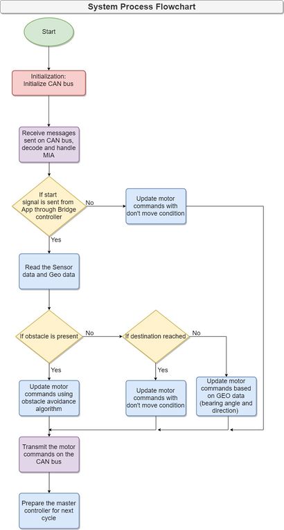
| − | The master controller gets start-stop command from bridge controller | + | [[File:Cmpe243_S19_master_SW_flowchart.jpg|right|thumb|Master Controller Process Flowchart|410px]] |
| + | The master controller gets start-stop command from bridge controller. This signal is sent from the mobile application by the user. From each ultrasonic sensors, it gets distance to obstacle and compares it to threshold value. The master sees the following conditions with respect to obstacles from the three ultrasonic sensor: left, front and right. | ||
| + | {| class="wikitable" | ||
| + | |- | ||
| + | ! scope="col"| Case number | ||
| + | ! scope="col"| Left sensor value | ||
| + | ! scope="col"| Middle sensor value | ||
| + | ! scope="col"| Right sensor value | ||
| + | ! scope="col"| Motor reaction | ||
| + | ! scope="col"| Motor Command Drive | ||
| + | ! scope="col"| Motor Command Steer | ||
| + | |||
| + | |- | ||
| + | ! scope="row"| 0 | ||
| + | | 0 | ||
| + | | 0 | ||
| + | | 0 | ||
| + | | movFrwd | ||
| + | | drive_front | ||
| + | | steer_front | ||
| + | |||
| + | |- | ||
| + | ! scope="row"| 1 | ||
| + | | 0 | ||
| + | | 0 | ||
| + | | 1 | ||
| + | | movSoftLeft | ||
| + | | drive_moderate | ||
| + | | steer_soft_left | ||
| + | |||
| + | |- | ||
| + | ! scope="row"| 2 | ||
| + | | 0 | ||
| + | | 1 | ||
| + | | 1 | ||
| + | | movModLeft | ||
| + | | drive_slow | ||
| + | | steer_moderate_left | ||
| + | |||
| + | |- | ||
| + | ! scope="row"| 3 | ||
| + | | 0 | ||
| + | | 1 | ||
| + | | 0 | ||
| + | | movModLeft | ||
| + | | drive_slw | ||
| + | | steer_moderate_left | ||
| + | |||
| + | |- | ||
| + | ! scope="row"| 4 | ||
| + | | 1 | ||
| + | | 1 | ||
| + | | 0 | ||
| + | | movModRight | ||
| + | | drive_slow | ||
| + | | steer_moderate_right | ||
| + | |- | ||
| + | ! scope="row"| 5 | ||
| + | | 1 | ||
| + | | 0 | ||
| + | | 0 | ||
| + | | movSoftRight | ||
| + | | drive_moderate | ||
| + | | steer_soft_right | ||
| + | |||
| + | |- | ||
| + | ! scope="row"| 6 | ||
| + | | 1 | ||
| + | | 0 | ||
| + | | 1 | ||
| + | | movFrwd | ||
| + | | drive_forward | ||
| + | | steer_front | ||
| + | |||
| + | |- | ||
| + | ! scope="row"| 7 | ||
| + | | 1 | ||
| + | | 1 | ||
| + | | 1 | ||
| + | | movReverse | ||
| + | | drive_reverse | ||
| + | | steer_moderate_left | ||
| + | |- | ||
| + | |} | ||
| + | The '1' represents obstacle detected and '0' represents no obstacle. This is based on the thresholds determined through trials and error method. The threshold is distance after which the object is to be avoided. The sensor can sense upto 125 inch in front of it and has 2 inch blind spot right in front of it. Threshold selection has to be such that, the turns would be able to avoid obstacle without crashing into it and some delay to transmit the motor command and then motor latency respond to the master controller command. It was observed that with higher speed higher threshold are required to cater for motor controller latency. Also the threshold for front sensor is higher than the adjacent left and right sensor because of the position and bending radius of car. The car reduces speed on turning at corners or around edges as well to avoid collision. There are 2 levels of turning possible on each side of the car. It is dependent on the size of the obstacle observed by combination of the sensor. When front and any adjacent signal detects '1', the object to be avoided is assumed to be thicker or wide (wall or corner) and needs to be turned away by a larger angle. For people travelling into the cars peripherally the car turns by smaller angle or 'soft_steers'. When object is detected by all 3 sensors we assume it has run into a corner or dead end and needs to be reversed. This is possible by reversing the motor direction in left to get out of that spot and then navigating to the destination. | ||
| + | |||
| + | Next it checks for direction and magnitude from geo sensor input to send motor controller commands for driving and steer control. The geo sensors sends direction for turning towards destination and magnitude for turning angle. This turning angle is then converted to 'soft_steer' and 'mod_steer' based on angle thresholds. Upon reaching the destination location the geo sensor sends stop signal to Master Controller. The Master Controller than issues motor stop command to the Motor Controller. Thus the geo signal helps Master with navigation to destination. | ||
| + | |||
| + | Also the master controller monitors and displays heartbeat for remaining controllers through on board LED. If any board resets, the CAN message received is MIA and onboard LED for that controller goes off. | ||
=== Technical Challenges === | === Technical Challenges === | ||
| Line 514: | Line 962: | ||
Problem Resolution: This was a programming bug. Code restructuring and verifying the conditions helped solve this problem. The nested if structure had most frequently used command at the top of nested if, to reduce time lag. This proved unreliable as the frequently used command had ultrasonics default condition which overshadowed the geo data analysis part. Putting this condition to the end of the nested structure helped solve this default behaviour taking precedence everytime. Geo data had same conditions for stop and no data received from geo sensors. Hence the car stopped when no geo data was received. Remedying this with separate constants for each helped solve this problem. | Problem Resolution: This was a programming bug. Code restructuring and verifying the conditions helped solve this problem. The nested if structure had most frequently used command at the top of nested if, to reduce time lag. This proved unreliable as the frequently used command had ultrasonics default condition which overshadowed the geo data analysis part. Putting this condition to the end of the nested structure helped solve this default behaviour taking precedence everytime. Geo data had same conditions for stop and no data received from geo sensors. Hence the car stopped when no geo data was received. Remedying this with separate constants for each helped solve this problem. | ||
| + | '''Evaluating both Geo sensors and Ultrasonic''' | ||
| + | |||
| + | Problem Summary: The conditions for steering was taken with both ultrasonic and geo sensors data. This created delay and uncertainty in decision making even with checking ultrasonic first. | ||
| + | |||
| + | Problem Resolution: Restructuring the code to check all possible outcomes of Ultrasonic and then checking Geo sensors outcome. This made sure ultrasonic obstacle detection always got higher priority and faster response then geo navigation outcome. | ||
<BR/> | <BR/> | ||
== Mobile Application == | == Mobile Application == | ||
| − | |||
| − | === | + | === Description === |
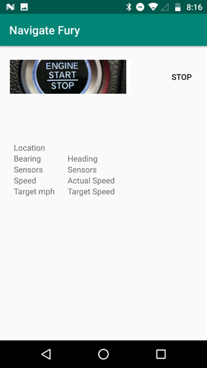
| + | The mobile application facilitates functionalities such as starting and stopping the device. It features a dashboard where live readings from sensors and other, important parameters such as heading, current location are displayed. The application was built using the android platform, the major reasons for this choice were the high support of Android and also some prior background in Java. | ||
| + | |||
| + | A good getting started with Android tutorial is mentioned [https://developer.android.com/training/basics/firstapp here]. | ||
| + | |||
| + | <center> | ||
| + | <table> | ||
| + | <tr> | ||
| + | <td> | ||
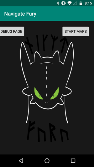
| + | <li style="display: inline-block;"> [[File:UI.png|300px|thumb|left||Home]] </li> | ||
| + | <li style="display: inline-block;"> [[File:Debug page.png|300px|thumb|left||Dashboard]]</li> | ||
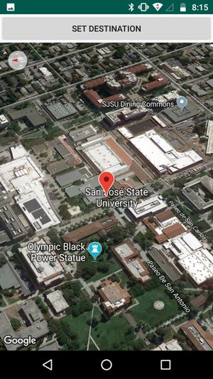
| + | <li style="display: inline-block;"> [[File:Navigation.jpg|300px|thumb|left||Destination Page]] </li> | ||
| + | |||
| + | </td> | ||
| + | </tr> | ||
| + | </table> | ||
| + | </center> | ||
=== Software Design === | === Software Design === | ||
| − | + | ||
| + | The software of the system is divided into three activities. | ||
| + | |||
| + | 1. Home Activity | ||
| + | |||
| + | 2. Dashboard Activity | ||
| + | |||
| + | 3. Maps Activity | ||
| + | |||
| + | '''1. Home Activity''' | ||
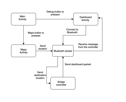
| + | * As shown in the flow chart below. Home Activity is the main activity of the application and it spawns the Dashboard or the Maps Activity. | ||
| + | [[File:App overview.png|500px|thumb|centre||Navigate fury overview]] | ||
| + | |||
| + | * It checks for basic access rights and sanity checks the configuration of the device. The access rights that this activity or this application requires are - | ||
| + | ** Location access | ||
| + | ** Bluetooth access | ||
| + | |||
| + | Once these accesses are granted the user can proceed to the next selection. | ||
| + | |||
| + | The Dashboard and Maps Activity both interfaces with the Bluetooth device and opens an RF comm socket, which is used to send or receive messages to the Bridge controller. The RF comm socket is just another type of socket which is maintained in a background thread so that it doesn't block the main UI thread. This can be achieved either by the Async Task or by creating a background thread which keeps running, polling for new messages from the client. | ||
| + | |||
| + | The psuedo code for the Home Activity is given below: | ||
| + | |||
| + | 1. Check for location permission | ||
| + | if permission is not granted | ||
| + | Ask user for location access | ||
| + | |||
| + | 2. Check for bluetooth permissions | ||
| + | if bluetooth access granted and bluetooth is off | ||
| + | Ask the user to turn on Bluetooth | ||
| + | |||
| + | 3. Add two buttons in the layout | ||
| + | set onclick listeners for both buttons | ||
| + | Dashboard button will start the intent of the dashboard activity and the map button will start the intent of the maps activity | ||
| + | |||
| + | 2. '''Dashboard activity''' | ||
| + | |||
| + | *This Activity features Bluetooth connectivity and also the layout for receiving messages from the Bridge controller. | ||
| + | *The Bluetooth connection is maintained in a background thread such that it doesn't interfere with the UI thread. | ||
| + | The pseudo code for this activity is shown below: | ||
| + | |||
| + | Bluetooth connection | ||
| + | // We can either hardcode the bluetooth mac address or get it by scanning the device. | ||
| + | // Recommended method in this usecase is hard coding the bluetooth mac address. | ||
| + | a. Pair the Bluetooth device with the android phone. | ||
| + | b. Get the mac address shown under the Bluetooth connection. Hardcode the mac address in a String. | ||
| + | c. Get a remoteDevice object for the mac address. If the device with the same mac address is not paired in your Bluetooth connection, this will return a null object. | ||
| + | d. Create a Bluetooth socket object from the remote device in the last step. | ||
| + | |||
| + | Managing Bluetooth operations in a thread | ||
| + | Extend a class of type thread. Initialize the class such that it opens two streams from the Bluetooth socket. One is the input stream and the other is the output stream. | ||
| + | Connect to the Bluetooth socket. | ||
| + | |||
| + | |||
| + | Sending messages | ||
| + | Using the new class created in the step above. We can send messages by the writing message to the output stream generated in the constructor of the new class. | ||
| + | |||
| + | Receiving messages | ||
| + | a. Override the run method in the thread class, to receive messages in the buffer of any size. The received message should be a specialized format and for integrity reasons, should end with a special character which can mark an end of a message. | ||
| + | b. Create a handler in the onCreate method of the activity such that this handler is called every time a new message is received and this handler can then update the UI components. | ||
| + | |||
| + | Creating a layout for UI components | ||
| + | The UI of this application is fairly simple. However, to prevent layout elements from crossing each other, we can use a linear layout. | ||
| + | |||
| + | 3. '''Maps activity''' | ||
| + | |||
| + | Maps activities is a fairly simple activity which extends a Fragment Activity and implements onMapReady callback. On MapReady callback is used as a callback whenever the map is ready to be used.The pseudo code for this activity is as under - | ||
| + | |||
| + | a. Add maps fragment in the xml | ||
| + | xmlns:map="http://schemas.android.com/apk/res-auto" | ||
| + | xmlns:tools="http://schemas.android.com/tools" | ||
| + | android:id="@+id/map" | ||
| + | android:name="com.google.android.gms.maps.SupportMapFragment" | ||
| + | android:layout_width="match_parent" | ||
| + | android:layout_height="match_parent" | ||
| + | tools:context=".MapsActivity" | ||
| + | |||
| + | b. Override the onMapReady callback which will be called when the map is ready for use. | ||
| + | |||
| + | c. Set onMapclick listener to select location on the map. | ||
| + | setDestination.setOnClickListener(new View.OnClickListener() { | ||
| + | @Override | ||
| + | public void onClick(View v) { | ||
| + | String loc = null; | ||
| + | if (dest_loc!=null) { | ||
| + | loc = df2.format(dest_loc.latitude)+ ", " + df2.format((dest_loc.longitude) ); | ||
| + | Log.println(Log.INFO, "Location sent", loc); | ||
| + | } | ||
| + | if (loc!=null) | ||
| + | sendSignal(loc); | ||
| + | } | ||
| + | }); | ||
=== Technical Challenges === | === Technical Challenges === | ||
| − | + | '''1. Message parsing''' | |
| − | + | ||
| − | + | Problem: The incoming message from the Bridge controller contained a lot of messages, due to which the output on the Android application was random as the thread fetched data way faster than the client can send it. | |
| − | + | ||
| + | Solution: The solution to this problem was to structure the message such that a line was terminated with a special character. So, the message until this character is found can be considered as one packet. | ||
| + | |||
| + | '''2. Passing message from the map activity to the Bluetooth activity. | ||
| + | |||
| + | Problem: To avoid redundancy and to send a message from the server(app) to the client. In this case, we were sending the destination location to the controller. Since the activities which catered to Bluetooth connection was different than the maps activity, passing data between these activities was challenging given that the Bluetooth socket gets destroyed after one activity exits. | ||
| + | |||
| + | Solution: A workaround was made in this case. The Bluetooth class was inherited by this activity such as a Bluetooth connection can be created and the destination can be sent to the client. | ||
| − | |||
<BR/> | <BR/> | ||
| + | |||
== Conclusion == | == Conclusion == | ||
| − | + | Successfully designed, implemented and tested autonomous car navigation as part of course requirement. Additionally, we worked as a team and completed the assigned tasks successfully. | |
| − | + | We achieved following learning goals: | |
| + | *Usage of CAN bus | ||
| + | Working extensively with CAN bus for communication has given us better understanding of this communication protocol. With CAN, it became really easy to get system status in real time instead of using print statements over UART. Further, understanding the DBC file format made us more aware about the data being transmitted. | ||
| + | *GIT version control | ||
| + | With GITLab it became really easy for the team members to work on their portion of code and then push it to their respective branch for sharing with others. The merge resolve gave valuable peer feedback. The simplicity of use of the tool was added bonus to learn and do necessary version control. | ||
| + | *Unit Testing | ||
| + | Unit testing helped us to remove programming bugs at development stage itself. Anytime with new logic insertion, the unit test would give warning if the modified algorithm is compatible with the overall logic or not. It proved to be challenging task with the developing logic be it use of static elements or restructuring the code for ease of unit testing. | ||
| + | *Team work and Dedication | ||
| + | Team members were always open minded about approaching difficulties. Everyone worked diligently on their module often staying overnight to finish task at hand. The team structure would evolve with the requirement of that week. No one limited themselves to one particular task and always went out of their way to lend helping hand. | ||
=== Project Video === | === Project Video === | ||
| + | |||
| + | https://youtu.be/-F9lSJ-Cud8 | ||
=== Project Source Code === | === Project Source Code === | ||
| + | *[https://gitlab.com/BPradnya/light-fury Gitlab Code Link] | ||
=== Advise for Future Students === | === Advise for Future Students === | ||
| − | + | Do '''lots of field testing!''' Initially for obstacle avoidance then with geographical sensors. Finally with both integrated on the designed PCB. As this is mostly last minute, one can miss the minor/major bugs at this crucial stage. So do lots of field testing and analyse the behavior of the autonomous car. | |
| + | |||
| + | '''Use reliable sensors''' and not only cheap ones. Sensors provide the controller with reliable and crucial data for navigating autonomously. Hence selected sensor should be repeatable and reliable. | ||
| + | |||
| + | '''Using CAN bus for debugging''' the issues in the car. CAN has graphical tools which can make debugging easier. In our case, we noticed right away that sensor values were jumping randomly and triggering falsely. We caught this immediately over the Bus Master representation of CAN data values. | ||
| + | |||
| + | '''Order extra components!''' This is important as during testing your component may get damaged. Replacing them at that point is time consuming and frustrating. So always order more components than requirement. You can always return the unused components later. | ||
| + | |||
| + | '''Follow the grading rubrics'''. The rubrics is designed such that it tests stages of development for the autonomous car. Completing the rubrics goals is completing the basic system functionality and testing them with ISA or Professor. They provide valuable feedback on the current and next course of action. | ||
=== Acknowledgement === | === Acknowledgement === | ||
| + | We would like to acknowledge the following people for their help in completing this project: | ||
| + | *Prof. Preetpal Kang for teaching CAN and Git and guiding throughout the project | ||
| + | *Prof. Kai Kai Liu for the Car chassis and geographical sensor | ||
| + | *[https://www.linkedin.com/in/pratap-desai-03/ Pratap] for advice on obstacle avoidance | ||
| + | *Maxbotix for a generous student discount on their product. | ||
| + | *Microchip for the free CAN ICs. | ||
| − | === References === | + | === References Used === |
| + | *[http://www.nxp.com/documents/user_manual/UM10360.pdf LPC_USER_MANUAL] | ||
| + | *[http://www.microchip.com/wwwproducts/en/en010405 CAN transceiver] | ||
| + | *[https://dl.djicdn.com/downloads/nazam-v2/en/NAZA-M_Quick_Start_Guide_v1.26_en.pdf NAZA datasheet] | ||
| + | *[https://en.wikipedia.org/wiki/Hall_effect_sensor Hall Effect Sensor Wikipedia] | ||
| + | *[https://www.parallax.com/product/28015 Ultrasonic Datasheet] | ||
| + | *[http://www.electronicaestudio.com/docs/istd016A.pdf HC05 datasheet] | ||
| + | *[https://www.digi.com/resources/documentation/digidocs/PDFs/90000976.pdf Xbee API Guid] | ||
| + | *[https://www.digi.com/products/embedded-systems/rf-modules/2-4-ghz-modules/xbee-zigbee Buy Xbee Zigbee] | ||
| + | *[https://developers.google.com/maps/documentation/android-api/ Maps Android API] | ||
| + | *[https://traxxas.com/sites/default/files/Slash%204x4%20RPM.pdf RPM sensor 6520 Installation Guide] | ||
| + | *[https://traxxas.com/support/Programming-Your-Traxxas-Electronic-Speed-Control Traxxas Guide for Configuration of Electronics Speed Control] | ||
| + | *[https://developer.android.com/guide/topics/connectivity/bluetooth Bluetooth API Android] | ||
| + | *[https://developers.google.com/maps/documentation/android-sdk/start Getting started with maps] | ||
Latest revision as of 01:05, 24 May 2019
Contents
LightFury
Ultrasonic and Geo Sensor Based Self-Navigating Autonomous Car using CAN communication bus.
Abstract
LightFury is an autonomous electric car project that aims to bring different embedded system paradigms together and consolidate them with industry level sophistication and robustness. This project will feature an RC car which will employ different sensors and motors to navigate the track without human assistance. Every sensor and motor combined with a dedicated functionality is managed and processed by a controller. Such different controllers will communicate with the master node using the CAN bus protocol. Real time interaction with the car for communicating destination and getting car updates is possible with bridge controller and mobile application. The autonomous car navigation is a result of all electronic module functioning harmoniously to reach the destination location.
The navigation is based on destination position and car position. The autonomous car navigates with the help of GPS and compass along the checkpoints. Also, upon detecting obstacle, the car effectively navigates away from obstacle coming into its path. The motor controller effectively controls speed at turning and on ramp. Using the communication bridge and on board LED indicators we can have interpretation of the controller decisions. Also, the CAN bus communication can be used to observe the messages and sensor output on GUI or graphs. Thus we can observe the navigation decisions taken by the autonomous car.
Introduction
The project is divided into 7 modules:
- Master Controller
- Motor Controller
- Ultrasonic Sensor Controller
- GPS Controller
- Android application and Bluetooth Connectivity
- Hardware (PCB designing and Electronic layout)
- Testing and Verification
The system has five SJOne Boards that run FreeRTOS and communicate with CAN bus. The car uses low power source for Boards and Sensory Units and high power source for Motor Driving Unit. The LEDs on each board are used to indicate status of controllers. The system is mounted and arranged on Traxis chassis. The final autonomous car is functional and compact unit.
Team Members & Responsibilities
Project Link: Gitlab Link
- Sensors
- Ultrasonic
- Compass
- RPM Sensor
- PCB Design
- Testing, Integration & Repository Maintenance
Schedule
| Week# | Start Date | Task | Status | Completion Date |
|---|---|---|---|---|
| 1 | 02/12/2019 |
|
Completed | 02/12/2019 |
| 2 | 02/19/2019 |
|
Completed | 02/19/2019 |
| 3 | 02/26/2019 |
|
Completed | 02/26/2019 |
| 4 | 03/05/2019 |
|
Completed | 03/09/2019 |
| 5 | 03/12/2019 |
|
Completed | 03/19/2019 |
| 5 | 03/19/2019 |
|
Completed | 03/26/2019 |
| 6 | 03/26/2019 |
|
Completed | 04/02/2019 |
| 7 | 04/02/2019 |
|
Completed | 04/09/2019 |
| 8 | 04/09/2019 |
|
Completed | 04/16/2019 |
| 9 | 04/16/2019 |
|
Completed | 04/23/2019 |
| 10 | 04/23/2019 |
|
Completed | 04/30/2019 |
| 10 | 04/23/2019 |
|
Completed | 04/30/2019 |
| 11 | 04/30/2019 |
|
Completed | 05/07/2019 |
| 12 | 05/07/2019 |
|
Completed | 05/14/2019 |
| 12 | 05/22/2019 |
|
Completed | 05/22/2019 |
Parts List & Cost
| Item# | Part Desciption | Vendor | Qty | Cost |
|---|---|---|---|---|
| 1 | RC Car | Traxxas | 1 | From Prof. KaiKai Liu |
| 2 | CAN Transceivers MCP2551-I/P | Microchip | 15 | Free Samples |
| 3 | Naza GPS and compass | NazaGPS | 1 | $34 |
| 4 | LIPO Batteries + Charger | 1 | with car package | |
| 5 | 7" LCD | 1 | ||
| 6 | RPM 6520 Traxxas | Amazon | 1 | $11.67 |
| 7 | Parallax Ping Ultrasonic Sensor | Parallax ping | 4 | $150 |
| 8 | Sensor Mounts | Sensor Mounts | 4 | $11.96 |
| 9 | PCB | PCBWay | 1 | $30.00 |
| 10 | SJOne board | 5 | From Preet |
DBC File
VERSION ""

NS_ :
	BA_
	BA_DEF_
	BA_DEF_DEF_
	BA_DEF_DEF_REL_
	BA_DEF_REL_
	BA_DEF_SGTYPE_
	BA_REL_
	BA_SGTYPE_
	BO_TX_BU_
	BU_BO_REL_
	BU_EV_REL_
	BU_SG_REL_
	CAT_
	CAT_DEF_
	CM_
	ENVVAR_DATA_
	EV_DATA_
	FILTER
	NS_DESC_
	SGTYPE_
	SGTYPE_VAL_
	SG_MUL_VAL_
	SIGTYPE_VALTYPE_
	SIG_GROUP_
	SIG_TYPE_REF_
	SIG_VALTYPE_
	VAL_
	VAL_TABLE_

BS_:

BU_: DBG DRIVER IO MOTOR SENSOR LF_SENSOR LF_MOTOR LF_DRIVER LF_GEO LF_BRIDGE LF_DEBUG_NODE

BO_ 10 LF_BRIDGE_START_STOP: 1 LF_BRIDGE
 SG_ start_stop_flag : 0|2@1+ (1,0) [0|0] "ON/OFF" LF_DRIVER,LF_DEBUG_NODE

BO_ 11 LF_bridge_dest: 8 LF_BRIDGE
 SG_ dest_lat : 0|32@1+ (0.000001,0) [0|0] "Degree" LF_GEO
 SG_ dest_long : 32|32@1- (-0.000001,0) [0|0] "Degree" LF_GEO

BO_ 51 LF_SENSOR_HB: 1 LF_SENSOR
 SG_ sensor_hb : 0|1@1+ (1,0) [0|0] "HB" LF_DRIVER

BO_ 52 LF_MOTOR_HB: 1 LF_MOTOR
 SG_ motor_hb : 0|1@1+ (1,0) [0|0] "HB" LF_DRIVER

BO_ 53 LF_GEO_HB: 1 LF_GEO
 SG_ geo_hb : 0|1@1+ (1,0) [0|0] "HB" LF_DRIVER

BO_ 54 LF_BRIDGE_HB: 1 LF_BRIDGE
 SG_ bridge_hb : 0|1@1+ (1,0) [0|0] "HB" LF_DRIVER

BO_ 55 LF_DRIVER_HB: 1 LF_DRIVER
 SG_ driver_hb : 0|1@1+ (1,0) [0|0] "HB" LF_SENSOR,LF_MOTOR,LF_GEO,LF_BRIDGE

BO_ 80 LF_SENSOR_DATA: 5 LF_SENSOR
 SG_ left_sensor : 0|8@1+ (1,0) [0|0] "Centimeters" LF_DRIVER,LF_BRIDGE
 SG_ front_sensor : 8|8@1+ (1,0) [0|0] "Centimeters" LF_DRIVER,LF_BRIDGE
 SG_ right_sensor : 16|8@1+ (1,0) [0|0] "Centimeters" LF_DRIVER,LF_BRIDGE
 SG_ rear_sensor : 24|8@1+ (1,0) [0|0] "Centimeters" LF_DRIVER,LF_BRIDGE

BO_ 81 LF_MOTOR_CMD: 1 LF_DRIVER
 SG_ MOTOR_CMD_drive_enum : 0|4@1+ (1,0) [0|0] "" LF_MOTOR
 SG_ MOTOR_CMD_steer_enum : 4|4@1+ (1,0) [0|0] "" LF_MOTOR

BO_ 82 LF_GEO_BT_LAT_LONG: 8 LF_GEO
 SG_ GEO_BT_lat_debug : 0|32@1+ (0.000001,0) [0|0] "Degree" LF_BRIDGE
 SG_ GEO_BT_long_debug : 32|32@1- (-0.000001,0) [0|0] "Degree" LF_BRIDGE

BO_ 83 LF_GEO_BT_COMP: 6 LF_GEO
 SG_ GEO_BT_comp_debug : 0|10@1+ (1,0) [0|0] "Degree" LF_BRIDGE,LF_DEBUG_NODE
 SG_ GPS_FIX : 10|3@1+ (1,0) [0|0] "" LF_BRIDGE,LF_DEBUG_NODE
 SG_ GPS_LOCK : 13|1@1+ (1,0) [0|0] "" LF_BRIDGE,LF_DEBUG_NODE
 SG_ GEO_BT_turning_angle_debug : 14|10@1- (-1,0) [0|0] "" LF_BRIDGE,LF_MOTOR,LF_DEBUG_NODE
 SG_ CURRENT_CHECKPOINT : 24|8@1+ (1,0) [0|0] "" LF_BRIDGE,LF_MOTOR,LF_DEBUG_NODE
 SG_ CURRENT_RADIUS : 32|16@1+ (0.01,0) [0|0] "Meters" LF_BRIDGE,LF_MOTOR,LF_DEBUG_NODE

BO_ 84 LF_GEO_DATA: 2 LF_GEO
 SG_ direction_geo : 0|3@1+ (1,0) [0|1] "GeoDirection" LF_DRIVER
 SG_ magnitude_geo : 3|8@1+ (1,0) [0|180] "Degree" LF_DRIVER

BO_ 85 LF_CHECKPOINT_BT_LAT_LONG: 8 LF_GEO
 SG_ CHECKPOINT_BT_lat_debug : 0|32@1+ (0.000001,0) [0|0] "Degree" LF_BRIDGE,LF_DEBUG_NODE
 SG_ CHECKPOINT_BT_long_debug : 32|32@1- (-0.000001,0) [0|0] "Degree" LF_BRIDGE,LF_DEBUG_NODE

BO_ 600 LF_GEO_CAN_DEBUG_MSG: 3 LF_GEO
 SG_ GEO_DEBUG_lat : 0|8@1+ (1,0) [0|0] "Degree" LF_DEBUG_NODE
 SG_ GEO_DEBUG_long : 8|8@1+ (1,0) [0|0] "Degree" LF_DEBUG_NODE
 SG_ GEO_DEBUG_comp : 16|8@1+ (1,0) [0|0] "Degree" LF_DEBUG_NODE

BO_ 601 LF_MOTOR_CAN_DEBUG_MSG: 7 LF_MOTOR
 SG_ Duty_cycle : 0|16@1+ (0.1,0) [0|0] "Percent" LF_DEBUG_NODE,LF_BRIDGE
 SG_ TargetSpeed : 16|16@1+ (0.1,0) [0|0] "MpH" LF_DEBUG_NODE,LF_BRIDGE
 SG_ car_mph : 32|16@1+ (0.1,0) [0|0] "MpH" LF_DEBUG_NODE,LF_BRIDGE
 SG_ axle_rps : 48|8@1+ (1,0) [0|0] "Rot/S" LF_DEBUG_NODE,LF_BRIDGE

BA_ "FieldType" SG_ 81 MOTOR_CMD_drive_enum "MOTOR_CMD_drive_enum";
BA_ "FieldType" SG_ 81 MOTOR_CMD_steer_enum "MOTOR_CMD_steer_enum";

VAL_ 81 MOTOR_CMD_drive_enum 1 "drive_forward" 2 "drive_moderate" 3 "drive_slow" 4 "drive_stop" 5 "drive_reverse";
VAL_ 81 MOTOR_CMD_steer_enum 1 "steer_front" 2 "steer_soft_left" 3 "steer_moderate_left" 4 "steer_soft_right" 5 "steer_moderate_right";
System Architecture
Printed Circuit Board
Initial prototyping was done on wire wrapping board for a common CAN bus and power input to all the controllers. Over time on finalizing the layout and components, we designed a PCB to have a compact and stable connections for our electronic and mechanical components. Planned a single PCB to place and route CAN transceivers and eliminate dangling wires. The PCB was designed with Eagle CAD software tool. Components were placed on the design after careful consideration for compactness and routing constraints. The design was modified multiple time to cater for new requirement. Finally, the designed PCB was placed on the chassis for stable and compact car design.
CAN Communication
Controlled Area Network or CAN is broadcast bus used in modern autonomous car systems for reliably communicating between devices. Here we use CAN bus to communicate between different controllers and debug with CAN messages. An errorneous node goes in bus off mode and other node keep communicating over CAN bus. This is why CAN is preferred over other communication protocols. Using PCAN dongle we can debug CAN communication on the bus in real time. These messages have helped in developing the navigation algorithm after observing the system in real time and monitoring CAN communication channel.
The CAN Bus physical design and communication is described in this section. The CAN controller present over SJOne board communicates to external transceiver over Rx and Tx. CAN transceiver transmit the message to CAN bus using differential signals. 0 is the dominant bit. This means that message with lower CAN message ID wins the bus arbitration and transmits its message on the bus. The other transceiver stops transmitting and waits for the next clock cycle to begin arbitration. Hence CAN message ID also acts as priority indicator. This arrangement is terminated with 2 terminal resistors of 120 Ohm. This removes signal reflection from the node end for combating echo from the signal. Due to differential means of transmitting the signal, the CAN bus is immune to noise loss and interference. All transceivers receive the CAN message. Only the intended terminal decodes the message. In case the message is not received by the terminal it goes into MIA state and consequent action can be decided by the user. This makes CAN convenient to be used in any applications.
The CAN follows certain data formatting method known as DBC. With the help of CAN transceivers, each sensor module sends data in DBC format to the controller. The data from ultrasonic sensor helps in obstacle detection. The GPS and Compass Module helps with navigation. The LCD gives live information of component status and values. Finally there is motors and control unit for navigating the car as per the commands from controller. All this controllers share information over CAN bus.
The CAN DBC file is unique format for information storage into structure and recording sender and receiver of the CAN network. It include the different message IDs along with message format and scale offset operations if any. Also there can be debugging node which keeps note of all the node data and can be used to observe the CAN communication. The DBC file comes handy while observing CAN operations in action with the help of Peak CAN. This became really helpful while observing sensor values in graph to detect false triggering.
DBC File
Sensor ECU
The sensor ECU is consist of SJOne board interfaced with four Parallax ping ultrasonic sensors. The primary objective of sensor ECU is to detect the obstacles and provide the corresponding information to the master controller in order to avoid those obstacles. According to beam angles, each sensor is mounted in such a way that the car can avoid the obstacles present in front and rear of the car. Based on the acquired information from sensors, distance is calculated and forwarded to the master controller over CAN bus. Based on the previous project reports, Parallax ping sensors were decided for this project as they provided reliable outputs with better range.
Parallax ping
The Parallax ping sensor works on 5V supply voltage. It provides precise distance measurement ranging from about 2 cm to 3 meters. Beyond the mentioned range, the measurement provided by the sensor is not accurate. The sensor operates at 40 kHz. Blinking of LED provided on the sensor depends on triggering frequency. It has only one pin called "Signal" pin for triggering and listening to the echo pulse, which reduces hardware complexity. The distance from the obstacle is calculated by measuring the width of echo pulse and multiplying it with a constant (speed of sound in air). Also, there are some scenarios under which these sensors won't give proper readings such as:
- Object is too small to reflect enough sound back to the sensor
- Obstacle with the reflective surface will reflect sound at a shallow angle ( < 45 degrees), which won't be reflected back towards the sensor
- The sound pulse gets reflected off the floor when the sensor is mounted low on the device
|
|
|
|
Hardware Design
Four ultrasonic sensors are used to detect obstacle on left, front, right and rear of the car. The sensor has 124 inches (3.1m) detection range for an obstacle in line of sight. All ultrasonic sensors are mounted upright with an upward tilt to avoid ground reflection. The sensors have a minimum overlap of detection area and have a blind spot too close to the car. All the sensors are interfaced with SJOne board on port 2. Four GPIO pins are used for each sensor and external interrupts are enabled for those pins. The measured distance is transmitted over CAN bus using CAN transceiver (MCP 2551).
Hardware Interface
- Pin 2.1 of SJOne board is configured as GPIO and is connected to the signal pin (SIG) of the left sensor. External interrupt for rising and falling edge is enabled to calculate the distance from an obstacle if any.
- Pin 2.2 of SJOne board is configured as GPIO and is connected to the signal pin (SIG) of the front sensor. External interrupt for rising and falling edge is enabled to calculate the distance from an obstacle if any.
- Pin 2.3 of SJOne board is configured as GPIO and is connected to the signal pin (SIG) of the right sensor. External interrupt for rising and falling edge is enabled to calculate the distance from an obstacle if any.
- Pin 2.4 of SJOne board is configured as GPIO and is connected to the signal pin (SIG) of the rear sensor. External interrupt for rising and falling edge is enabled to calculate the distance from an obstacle if any.
- Pin 0.0 of SJOne board is configured as RD1 and is connected to RXD pin (Pin 4) of MCP 2551 (can transceiver).
- Pin 0.1 of SJOne board is configured as TD1 and is connected to TXD pin (Pin 1) of MCP 2551 (can transceiver).
|
|
Software Design
Sensor triggering is implemented in the 100Hz periodic task. Sensors are triggered in sets instead of all the sensors triggering at the same time. This technique helped in minimizing signal interference between two adjoining sensors. The front and back sensors are triggered first and then the left and right sensors. Each sensor is fed with a 5us high pulse from the host controller and it emits a short ultrasonic burst and then starts listening for the echo. After sending out the pulse, the SIG pin becomes high and it goes low when the obstacle is detected. To sense this pulse, external interrupts are enabled. The maximum duration of this pulse is 18.5ms which denotes that there is no obstacle in front of the sensor. Given this time period, left and right sensors are triggered 20ms after front and back sensors are triggered. Each sensor is triggered at 20Hz, i.e., after 50ms.
After collecting the data from sensors, distance is calculated and it is transmitted over CAN bus. CAN transmission also takes place 100Hz task only so that updated values are sent at the faster speed. A heartbeat message is sent to the master controller indicating that the sensor controller is up and running. This message is sent using 10Hz periodic task.
Implementation
- Initialize the CAN bus either on can1 or can2 with baud rate of 100 kbps and RX/TX queues of size 100
- Configure the host controller pins 2.1, 2.2, 2.3 and 2.4 as GPIO pins (These pins are connected to SIG pin of left, front, right and rear sensor respectively)
- Enable the external interrupts for corresponding pins to detect rising and falling edge of the input pulse
- Set the micro-controller pin connected to SIG pin as an output
- Triggering the sensors:
- Send low signal from the controller to SIG pin (for a clean high pulse)
- Insert delay of 2us
- Send high signal from the controller to SIG pin
- Insert delay of 5us
- Send low signal from the controller to SIG pin
- Set the corresponding pin on the controller as an input which is connected to SIG pin
- Fetch the system uptime when rising edge interrupt occurs. The noted time can be considered as the "start_time" of the echo pulse.
- Fetch the system uptime when falling edge interrupt occurs. The noted time can be considered as the "stop_time" of the echo pulse.
- Calculate the distance from the obstacle. (Distance = ((start_time - stop_time)/147) in inches or Distance = ((start_time - stop_time)/57.14) in cm).
- Send the calculated distance to the master controller over the CAN bus.
Steps 4 to 10 are executed within the 100Hz periodic task.
Technical Challenges
Unreliable sonor sensors values
Problem Summary: Observed lots of false detection for sensor over CAN bus resulting in unwanted motor turning.
Problem Resolution: Reduced noise with the help of mounts to reduce vibration from car.
Reduced range when mounted on car
Problem Summary: Max detection range reduced when mounted on car with mounts.
Problem Resolution: Increased ampere to entire circuit to support complete functionality of sensors.
False triggering due to proximity
Problem Summary: All the sensors transmitted pulse at the same time which caused interference among adjoining sensors.
Problem Resolution: Revised sensor placement and triggered non-overlapping sensors at the same time to have minimum overlapping detection range and reduced interference among sensors.
Calculation Error
Problem Summary: Calculated distance in ISR which provided random results.
Problem Resolution: ISR should be kept simple and it should take less time for execution. So for distance calculation other function was created which was called in the 100Hz task.
Motor ECU
The motor controller is responsible for controlling the steering, direction of rotation ( forward, stop or reverse) and maintaining speed of the car. Additionally the Motor ECU also shelters an LCD to display parameters that are relevant for debugging certain features. It controls steering at different angles with the help of a servo motor. Rotation of the DC motor and speed is controlled by the ESC (Electronic Speed Controller). Different components that are in scope of Motor ECU:
- ESC
- DC Motor
- Servo Motor
- RPM Sensor (Hall Effect Sensor)
- LCD Module
Prerequisites
Getting Started with ESC
Before you begin calibration of a Traxxas ESC, please check the traxxas ESC datasheet and select appropriate profile:
- Sport Mode : 100% Forward, 100% Brakes, 100% Reverse
- Race Mode : 100% Forward, 100% Brakes, No Reverse
- Training Mode: 50% Forward, 100% Brakes, 50% Reverse
If you configure your ESC in Racing Mode, it will not respond to reverse signals.
To select the Sports Profile:
- Connect a fully charged battery pack to the ESC and turn on your transmitter.
- With the ESC off, press and hold the EZ-Set button until the LED turns solid green, then solid red and then begins blinking red (indicating the Profile numbers).
- When the LED blinks red once, release the EZ-Set button.
Calibrating ESC
ESC takes an PWM wave as input and controls direction and speed of the motor. In order for the ESC to repsond to PWM signals from SJone board, it needs to be calibrated.
- To move the motor speed forward in full throttle (100 % forward) the ESC requires a high pulse of """2 ms""".
- To """stop""" the motor a PWM pulse with on-time of 1.5 ms is required by the ESC.
- To move motor full-throttle backwards (100% backward) pulse of on-time """1 ms""" is required.
The PWM can be any frequency as long as above on-time condition is satisfied.
Example: For our project, we chose a 50 Hz frequency PWM wave for ESC as well as Servo. A 50 Hz frequency wave has 20 ms period. So get on-time of 1.5 ms, duty cycle needs to be 7.5%.
- 100% Forward - 2 ms - 10% duty cycle.
- Stop/Neutral - 1.5 ms - 7.5% duty cycle.
- 100% Backward - 1 ms - 5% duty cycle.
Steps to calibrate ESC
- Connect a fully charged battery pack to the ESC.
- Generate PWM for stop/neutral position.
- Press and hold the EZ-Set button. The LED will first turn green and then red. Release the EZ-Set button.
- When the LED blinks RED ONCE, generate PWM to the full throttle position (100% forward) and hold it there.
- When the LED blinks RED TWICE, generate PWM to the full reverse and hold it there.
- When the LED blinks GREEN ONCE, programming is complete. The LED will then shine green or red indicating the ESC is on and at neutral.
Hardware Design
The traxxas chassis came with ECU and servo controller. It has DC motor with servo control for turning. Working on 3.4 V/ 3000mAH power specifications it has axle to rotate all the four wheels. The feedback for PWM controlled speed attained is fed back through magnetic encoder. The front wheels have servo connection for turning. The chassis is placed on suspension unit for shock absorbing. An acrylic sheet is mounted over certain height on which the PCB and controller is placed. The motor controller PWM sends signals for DC motor and servo motor angles for driving the car.
RPM Sensor
Software Design
The motor gets signal from motor controller. The motor controller sends PWM signals for speed control of DC motor. Also it implements PID for uniform performance on ramp. For direction control, the servo has 2 levels of turning: soft and moderate. Depending on Driver Controller signal, the Motor Controller sends control signals to the motor. In case of communication loss from Master Controller, the Motor Controller displays CAN MIA condition on LED.
Technical Challenges
Finding PID constants
Problem Summary: For uniform speed over ramp, we implemented PID. However, calculating the constants for PID proved to be challenging due to oscillations of set speed.
Problem Resolution: Set discrete speed levels to prevent oscillations. Determined PID constants through trials and errors.
Determining RPM accurately
Problem Summary: No support available for motor encoder reed sensor.
Problem Resolution: After checking values on DSO, we noticed irregular output. We resolved it by using pull up resistor of 1k ohms.
Motor stop functioning before demo
Problem Summary: The motor stopped functioning even with correct power and signal input.
Problem Resolution: Had previously dismantled the chassis for encoder study. Re assembled the chassis to function correctly at demo.
Geographical Controller
The GPS module provides the location of the car on the earth in terms of latitude and longitude in degrees. This helps us know the current position of the car to navigate to the destination. We use this information to calculate range and bearing of the car to the destination and navigate according to this information. The compass gives the heading of the car with respect to North direction. In case the car is facing north, we will get 0 degree in compass. However, that is not always true and repeatable, hence the compass module needs caliberation. The gps and compass module together called as geo sensors form important part of Geographical Controller. The geo sensors module used in the car is from NAZA. The positioning of the module on the car is such that it is away from all the electromagnetic interference. The NAZA module communicates to geographical controller over UART to send data. This data is decoded by the Geographical Controller and send to Master Controller for further action to the Motor Controller. The part of the LCD display mounted on the car. The Geographical Controller interprets geo data for the Master Controller.
Hardware Design
The NAZA module consisting of both gps locator and compass is mounted on a stbaud rateand to avoid electromagnetic interference. The small notch on the device indicates the front direction of the compass. The module is interfaced to the SJOne board through UART at a baud rate of 115200 and called periodically in 10Hz frequency. The module is set to transmit mode hence receiver UART signal connection was used to just configure the GPS baud rate (Initially comes with 9600 ). It sends longitude and latitude (message id: 0x10) in one cycle and compass value (message id: 0x20) in the next. It also sends the version number (message id : 0x30), but it is not being used in the project.
The GPS module, works in all weather conditions, within an unobstructed line of sight communication using 4 or more GPS satellites. As more number of satellite in line of sight to a GPS receiver, higher is the accuracy in determining the position of the module. When a receiver receives a signal from one of the satellite, it calculates its distance from the satellite considering a 3-D sphere with the satellite located at the center of the sphere. Once the receiver receives the signal from at least three satellites out of 32, the receiver then points its location using trilateration process. The trilateration is the process of determining module position based on intersecting spheres of satellite distance to module. The GPS module calculates its distance from the satellite considering a 3-D sphere with the satellite located at the center of the sphere. Once the receiver does the same with 3 other GPS satellites, the receiver then proceeds to find the intersection point of the 3 spheres to calculate it’s location.A GPS requires at least 3 satellites to calculate 2-D position(latitude and longitude on a map) at mean sea level. However, it requires at least 4 satellites to find receivers 3-D position(latitude, longitude, and altitude)
|
|
Software Design
Bearing distance calculation: Bearing distance is the shortest distance from point A to point B on the great-cicle of the Earth. We have used Haversine Distance formula for the same
Bearing Angle Calculation: Bearing angle is the angle representing the desired navigation of the object with respect to the north in clockwise direction. The bearing angle is used to calculate the relative angle between two points on the map. In our case we used this to calculate the turning angle which tells the car how much to turn by and which direction.
Route Planning: We have designed a simple algorithm takes in source and destination as a input parameter. Also we have maintained a pool of checkpoints which avoids the car to approach inaccessible locations. The algorithm calculates midpoint of the source and destination and calculates the nearest checkpoint to it. Later this checkpoint will be used as a source to calculate midpoint and searched for the nearest checkpoint.
|
|
Technical Challenges
Unreliable GPS lock
Problem Summary: Was losing GPS lock necessary to get reliable GPS data.
Problem Resolution: Worked on the received data from the GPS module. Ensured GPS lock only upon receiving reliable and consistent geo data.
Noisy Compass Values
Problem Summary: The compass would not return same value at same position on switching power off and on again.
Problem Resolution: Initially, we thought it was just due to electromagnetic interference. However that was not just the case and the problem also was with compass calibration. Hence, implemented Kalman filter to reduce the sudden change in compass sensor values.
NOTE:
- Always for testing and data calibration, do it in an open air.
- Before testing the car for navigation, check multiple times (on the car) if there is any offset associated with the compass. If it does and the offset is constant, just compensate the offset in the received data.#
- Also try including filters to avoid compass angle fluctuations.
Communication Bridge Controller
The bridge controller is an interface of communication between car and the android Application controlling the car. Whatever commands App needs to send to the car, they are sent using Bridge Controller. All the data to be updated on the android application such as current location, car speed etc., is first sent to Bridge controller and then bridge controller sends the whole data to Android Application. Effectively, this controller communicates with each and every controller on the car and hence it is one of the crucial controllers. This controller also keeps the track of Master Controller's Heart Beat and Resets the car if master controller is not responding with heart beat.
Hardware Design
Bridge controller uses XBee Pro ZigBee module to communicate with the android application. ZigBee provides long range of communication i.e. approximately up to 100 meters when in line of sight or practically around 80 meters. However, there is no method to send data directly to ZigBee module from android application. Thus, to work around, a Bluetooth module is connected with Zigbee module. In this method, app can send data to Bluetooth module placed near to it. The BT module is connected to 1 ZigBee module directly with Tx-Rx wires. Hence The data received by BT is automatically transmitted to ZigBee module 1. This XBee receives the data from BT and sends it ahead to another XBee Pro; placed on the Bridge Controller on the car. The whole process occurs in reverse when any data is to be updated on the application from car. Thus, the hardware design of Bridge controller consists of 3 parts:-
- Bluetooth HC05 - XBee Pro Connection
- SJOne- XBee Pro Connection
- Integration for the communication
|
|
|
|
|
Software Design
The bridge controller being the controller to communicate with all the controller on the car has to adhere to the data formats send by the respective controllers. The controller should always fetch the data in different formats, parse it to convert to a single format and then send to mobile application. The process becomes reverse i.e. accept the data from application in one format and parse it to convert in different formats to send to every other controller.
The software design starts with initialization of few peripherals such as Can Bus for communication with other controllers, UART for XBee Pro module. These initializations are not periodic and hence initialized only once in Init functions.
Android Application sends 2 commands to the car using Bridge Controller:-
- Start/Stop the car:- This command is nothing but a 1 character command to start or stop the car manually. The car will not start driving till it receives start and destination co-ordinates from the application. However, it automatically stops after reaching the destination. The stop command is for manual stops.
- Destination of the car:- Android application gives the destination latitude and longitude coordinates in the form of comma separated string.
Both of the commands above need to be parsed in 2 different formats.
- Any of the command with single character is not Start/stop. Thus, start/Stop command validated before forwarding it to the CAN bus. It is then parsed and a boolean variable is given to master controller to start the car.
- Any command with single comma and greater than single character command is destination. This command is also validated and then transmitted to over CAN bus to Geo Controller for route determination.
These Two commands are generally not periodic and hence both of these are called in 10Hz periodic tasks.
void C_period_10Hz(uint32_t count)
{
    (void) count;

    if(xBee_receive(cmd_over_wireless,sizeof(cmd_over_wireless),3))
    {
        if(cmd_over_wireless[1] == '\0')
        {
            sendStartStop(cmd_over_wireless);
        }

        else
        {
            parseDestination(cmd_over_wireless);
        }
    }

    sendToApp();
The data updated from Car to the android application should be real time and hence the data is parsed in 100 Hz function. This data parsing is nothing but reading data from CAN bus using required message IDs and then converting it to a single string that is sent to the application.the data is read on every 10ms and then converted to string. This string is then sent to XBee module and effectively to Bluetooth to send it wirelessly to the application.
void C_period_100Hz(uint32_t count) {
    (void) count;

    Can_HB_tx(can1);

    can_rx(can1);

    parseData();
}
The whole software process is as follows:
|
|
Technical Challenges
Unable to send string ahead without termination
Problem Summary: The string coming from mobile application can not be forwarded since UART_gets() function requires termination character for string to be found complete.
Problem Resolution: The string coming from android application is already appended with '\n' so that the UART_gets() function will understand the completion of string. Hence, as soon as gets() will receive '\n', it will assume the command is complete and will forward to respective controller.
Delayed or no response to mobile switch on off data
Problem Summary: The on and off from the mobile app did not reliably switched on the Master Board. Often had to send start/stop signal multiple times to be registered by the Master bridge controller.
Problem Resolution: During code review we came to know to decode all CAN messages inside 1 while loop and assign the data into respective structure. Prior to that the code was designed to decode CAN message for each structure in different while loops. This also resolved the dim led glow of Master controller heartbeat.
Co ordination with Geo Controller for destination details
Problem Summary: The destination geo location data (longitude and latitude) is available to bridge controller from the mobile application before the geo controller gets geo fix. This caused synchronization problem as the destination coordinates was only sent once and not received by the geo controller.
Problem Resolution: Synchronized the data sending of destination coordinates by sending destination data only after geo fix was attained. the process on each controller after that were independent and did not require synchronization.
Master Module
The Master Controller is important part of the system. It takes data from Geo Controller board and Ultrasonic Controller board and decides the movement of the car through Motor Controller board. Also it tracks heart beat of all the controllers. Its main objective is to navigate to destination with obstacle avoidance. It receives navigation start signal from bridge controller. It stops navigation when Geo controller sends destination is reached. The master controller makes use of onboard LEDs as indicators of different status.
Hardware Design
The master controller is connected to all the controllers through CAN bus. The master receives and sends CAN message at 100 Hz frequency. It uses on board LEDs to display functioning controller which gives heartbeat. If any board goes off the CAN bus, from the LED off status we can come to know which board has reached MIA condition. To display sent motor command it sets appropriate numeric value on LED segment. For different states it indicates respective number on the 7 segment LED display. For navigating based on sensor value, logic is written with higher priority to sensor and stopping the car then to react to response from Geo Controller. Ultimately, the master has movement control of the car operations through commanding Master controller.
Software Design
The master controller gets start-stop command from bridge controller. This signal is sent from the mobile application by the user. From each ultrasonic sensors, it gets distance to obstacle and compares it to threshold value. The master sees the following conditions with respect to obstacles from the three ultrasonic sensor: left, front and right.
| Case number | Left sensor value | Middle sensor value | Right sensor value | Motor reaction | Motor Command Drive | Motor Command Steer |
|---|---|---|---|---|---|---|
| 0 | 0 | 0 | 0 | movFrwd | drive_front | steer_front |
| 1 | 0 | 0 | 1 | movSoftLeft | drive_moderate | steer_soft_left |
| 2 | 0 | 1 | 1 | movModLeft | drive_slow | steer_moderate_left |
| 3 | 0 | 1 | 0 | movModLeft | drive_slw | steer_moderate_left |
| 4 | 1 | 1 | 0 | movModRight | drive_slow | steer_moderate_right |
| 5 | 1 | 0 | 0 | movSoftRight | drive_moderate | steer_soft_right |
| 6 | 1 | 0 | 1 | movFrwd | drive_forward | steer_front |
| 7 | 1 | 1 | 1 | movReverse | drive_reverse | steer_moderate_left |
The '1' represents obstacle detected and '0' represents no obstacle. This is based on the thresholds determined through trials and error method. The threshold is distance after which the object is to be avoided. The sensor can sense upto 125 inch in front of it and has 2 inch blind spot right in front of it. Threshold selection has to be such that, the turns would be able to avoid obstacle without crashing into it and some delay to transmit the motor command and then motor latency respond to the master controller command. It was observed that with higher speed higher threshold are required to cater for motor controller latency. Also the threshold for front sensor is higher than the adjacent left and right sensor because of the position and bending radius of car. The car reduces speed on turning at corners or around edges as well to avoid collision. There are 2 levels of turning possible on each side of the car. It is dependent on the size of the obstacle observed by combination of the sensor. When front and any adjacent signal detects '1', the object to be avoided is assumed to be thicker or wide (wall or corner) and needs to be turned away by a larger angle. For people travelling into the cars peripherally the car turns by smaller angle or 'soft_steers'. When object is detected by all 3 sensors we assume it has run into a corner or dead end and needs to be reversed. This is possible by reversing the motor direction in left to get out of that spot and then navigating to the destination.
Next it checks for direction and magnitude from geo sensor input to send motor controller commands for driving and steer control. The geo sensors sends direction for turning towards destination and magnitude for turning angle. This turning angle is then converted to 'soft_steer' and 'mod_steer' based on angle thresholds. Upon reaching the destination location the geo sensor sends stop signal to Master Controller. The Master Controller than issues motor stop command to the Motor Controller. Thus the geo signal helps Master with navigation to destination.
Also the master controller monitors and displays heartbeat for remaining controllers through on board LED. If any board resets, the CAN message received is MIA and onboard LED for that controller goes off.
Technical Challenges
Levels of turning
Problem Summary: For turning on detecting obstacle, the large servo turning value would result in oversensitive behaviour.
Problem Resolution: Set 2 discrete servo levels for turning based on how many ultrasonic sensors are triggered. A moderate turning angle command is sent if two sensors (front or any one of the side sensors) and a soft turn command is sent if only one of the side sensor detects obstacle closer than threshold.
Determining threshold
Problem Summary: The car kept crashing even after detecting obstacle.
Problem Resolution: Determined threshold values through trials and errors. For high speed, large clearance is required for stopping distance. Ideally keep higher threshold value for front sensor than side sensors.
Unresponsive to GEO sensor data
Problem Summary: The motor command responded only to ultrasonic commands and disregarded the geo information even after including it the geo data in motor command decision making.
Problem Resolution: This was a programming bug. Code restructuring and verifying the conditions helped solve this problem. The nested if structure had most frequently used command at the top of nested if, to reduce time lag. This proved unreliable as the frequently used command had ultrasonics default condition which overshadowed the geo data analysis part. Putting this condition to the end of the nested structure helped solve this default behaviour taking precedence everytime. Geo data had same conditions for stop and no data received from geo sensors. Hence the car stopped when no geo data was received. Remedying this with separate constants for each helped solve this problem.
Evaluating both Geo sensors and Ultrasonic
Problem Summary: The conditions for steering was taken with both ultrasonic and geo sensors data. This created delay and uncertainty in decision making even with checking ultrasonic first.
Problem Resolution: Restructuring the code to check all possible outcomes of Ultrasonic and then checking Geo sensors outcome. This made sure ultrasonic obstacle detection always got higher priority and faster response then geo navigation outcome.
Mobile Application
Description
The mobile application facilitates functionalities such as starting and stopping the device. It features a dashboard where live readings from sensors and other, important parameters such as heading, current location are displayed. The application was built using the android platform, the major reasons for this choice were the high support of Android and also some prior background in Java.
A good getting started with Android tutorial is mentioned here.
|
|
Software Design
The software of the system is divided into three activities.
1. Home Activity
2. Dashboard Activity
3. Maps Activity
1. Home Activity
- As shown in the flow chart below. Home Activity is the main activity of the application and it spawns the Dashboard or the Maps Activity.
- It checks for basic access rights and sanity checks the configuration of the device. The access rights that this activity or this application requires are -
- Location access
- Bluetooth access
Once these accesses are granted the user can proceed to the next selection.
The Dashboard and Maps Activity both interfaces with the Bluetooth device and opens an RF comm socket, which is used to send or receive messages to the Bridge controller. The RF comm socket is just another type of socket which is maintained in a background thread so that it doesn't block the main UI thread. This can be achieved either by the Async Task or by creating a background thread which keeps running, polling for new messages from the client.
The psuedo code for the Home Activity is given below:
1. Check for location permission
   if permission is not granted
   Ask user for location access
2. Check for bluetooth permissions
   if bluetooth access granted and bluetooth is off
   Ask the user to turn on Bluetooth

3. Add two buttons in the layout
   set onclick listeners for both buttons
   Dashboard button will start the intent of the dashboard activity and the map button will start the intent of the maps activity
2. Dashboard activity
- This Activity features Bluetooth connectivity and also the layout for receiving messages from the Bridge controller.
- The Bluetooth connection is maintained in a background thread such that it doesn't interfere with the UI thread.
The pseudo code for this activity is shown below:
Bluetooth connection
  // We can either hardcode the bluetooth mac address or get it by scanning the device.
  // Recommended method in this usecase is hard coding the bluetooth mac address.
   a. Pair the Bluetooth device with the android phone.
   b. Get the mac address shown under the Bluetooth connection. Hardcode the mac address in a String.
   c. Get a remoteDevice object for the mac address. If the device with the same mac address is not paired in your Bluetooth connection, this will return a null object.
   d. Create a Bluetooth socket object from the remote device in the last step.
Managing Bluetooth operations in a thread
Extend a class of type thread. Initialize the class such that it opens two streams from the Bluetooth socket. One is the input stream and the other is the output stream.
Connect to the Bluetooth socket.
Sending messages
Using the new class created in the step above. We can send messages by the writing message to the output stream generated in the constructor of the new class.
Receiving messages
a. Override the run method in the thread class, to receive messages in the buffer of any size. The received message should be a specialized format and for integrity reasons, should end with a special character which can mark an end of a message.
b. Create a handler in the onCreate method of the activity such that this handler is called every time a new message is received and this handler can then update the UI components.
Creating a layout for UI components
The UI of this application is fairly simple. However, to prevent layout elements from crossing each other, we can use a linear layout.
3. Maps activity
Maps activities is a fairly simple activity which extends a Fragment Activity and implements onMapReady callback. On MapReady callback is used as a callback whenever the map is ready to be used.The pseudo code for this activity is as under -
a. Add maps fragment in the xml
xmlns:map="http://schemas.android.com/apk/res-auto"
           xmlns:tools="http://schemas.android.com/tools"
           android:id="@+id/map"
           android:name="com.google.android.gms.maps.SupportMapFragment"
           android:layout_width="match_parent"
           android:layout_height="match_parent"
           tools:context=".MapsActivity"
b. Override the onMapReady callback which will be called when the map is ready for use.
c. Set onMapclick listener to select location on the map.
setDestination.setOnClickListener(new View.OnClickListener() {
           @Override
           public void onClick(View v) {
           String loc = null;
               if (dest_loc!=null) {
                   loc = df2.format(dest_loc.latitude)+ ", " + df2.format((dest_loc.longitude) );
                   Log.println(Log.INFO, "Location sent", loc);
               }
               if (loc!=null)
                   sendSignal(loc);
           }
       });
Technical Challenges
1. Message parsing
Problem: The incoming message from the Bridge controller contained a lot of messages, due to which the output on the Android application was random as the thread fetched data way faster than the client can send it.
Solution: The solution to this problem was to structure the message such that a line was terminated with a special character. So, the message until this character is found can be considered as one packet.
2. Passing message from the map activity to the Bluetooth activity.
Problem: To avoid redundancy and to send a message from the server(app) to the client. In this case, we were sending the destination location to the controller. Since the activities which catered to Bluetooth connection was different than the maps activity, passing data between these activities was challenging given that the Bluetooth socket gets destroyed after one activity exits.
Solution: A workaround was made in this case. The Bluetooth class was inherited by this activity such as a Bluetooth connection can be created and the destination can be sent to the client.
Conclusion
Successfully designed, implemented and tested autonomous car navigation as part of course requirement. Additionally, we worked as a team and completed the assigned tasks successfully.
We achieved following learning goals:
- Usage of CAN bus
Working extensively with CAN bus for communication has given us better understanding of this communication protocol. With CAN, it became really easy to get system status in real time instead of using print statements over UART. Further, understanding the DBC file format made us more aware about the data being transmitted.
- GIT version control
With GITLab it became really easy for the team members to work on their portion of code and then push it to their respective branch for sharing with others. The merge resolve gave valuable peer feedback. The simplicity of use of the tool was added bonus to learn and do necessary version control.
- Unit Testing
Unit testing helped us to remove programming bugs at development stage itself. Anytime with new logic insertion, the unit test would give warning if the modified algorithm is compatible with the overall logic or not. It proved to be challenging task with the developing logic be it use of static elements or restructuring the code for ease of unit testing.
- Team work and Dedication
Team members were always open minded about approaching difficulties. Everyone worked diligently on their module often staying overnight to finish task at hand. The team structure would evolve with the requirement of that week. No one limited themselves to one particular task and always went out of their way to lend helping hand.
Project Video
Project Source Code
Advise for Future Students
Do lots of field testing! Initially for obstacle avoidance then with geographical sensors. Finally with both integrated on the designed PCB. As this is mostly last minute, one can miss the minor/major bugs at this crucial stage. So do lots of field testing and analyse the behavior of the autonomous car.
Use reliable sensors and not only cheap ones. Sensors provide the controller with reliable and crucial data for navigating autonomously. Hence selected sensor should be repeatable and reliable.
Using CAN bus for debugging the issues in the car. CAN has graphical tools which can make debugging easier. In our case, we noticed right away that sensor values were jumping randomly and triggering falsely. We caught this immediately over the Bus Master representation of CAN data values.
Order extra components! This is important as during testing your component may get damaged. Replacing them at that point is time consuming and frustrating. So always order more components than requirement. You can always return the unused components later.
Follow the grading rubrics. The rubrics is designed such that it tests stages of development for the autonomous car. Completing the rubrics goals is completing the basic system functionality and testing them with ISA or Professor. They provide valuable feedback on the current and next course of action.
Acknowledgement
We would like to acknowledge the following people for their help in completing this project:
- Prof. Preetpal Kang for teaching CAN and Git and guiding throughout the project
- Prof. Kai Kai Liu for the Car chassis and geographical sensor
- Pratap for advice on obstacle avoidance
- Maxbotix for a generous student discount on their product.
- Microchip for the free CAN ICs.
References Used
- LPC_USER_MANUAL
- CAN transceiver
- NAZA datasheet
- Hall Effect Sensor Wikipedia
- Ultrasonic Datasheet
- HC05 datasheet
- Xbee API Guid
- Buy Xbee Zigbee
- Maps Android API
- RPM sensor 6520 Installation Guide
- Traxxas Guide for Configuration of Electronics Speed Control
- Bluetooth API Android
- Getting started with maps
