Difference between revisions of "F18: 2048"
Proj user16 (talk | contribs) (→Hardware Interface) |
Proj user16 (talk | contribs) (→References Used) |
||
| (39 intermediate revisions by the same user not shown) | |||
| Line 1: | Line 1: | ||
=='''''2048''''' == | =='''''2048''''' == | ||
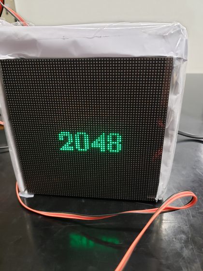
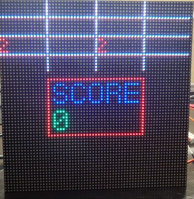
| − | + | [[File:2048start_screen.jpg|center|thumb|420px|Game Start Screen]] | |
== Abstract == | == Abstract == | ||
| − | 2048 is a game having a grid of numbered tiles (i.e., a power of 2) to combine them to create a tile with the number 2048. It is usually played on a 4x4 grid with tiles that slide smoothly when a player moves them towards the right, left, up or down. Every time a new tile will randomly appear in an empty spot on the display with a value of either 2 or 4. If two tiles of the same number collide then they will merge into one tile with a value of the sum of those two tiles. The game continues until no merge is possible. The game uses RGB LED matrix to display the 4x4 game grid and the scores. The player is given a choice to choose thumb joystick or an onboard accelerometer to give direction inputs; left, right, up and down. The Game Logic and the display are updated using | + | 2048 is a game having a grid of numbered tiles (i.e., a power of 2) to combine them to create a tile with the number 2048. It is usually played on a 4x4 grid with tiles that slide smoothly when a player moves them towards the right, left, up or down. Every time a new tile will randomly appear in an empty spot on the display with a value of either 2 or 4. If two tiles of the same number collide then they will merge into one tile with a value of the sum of those two tiles. The game continues until no merge is possible. The game uses RGB LED matrix to display the 4x4 game grid and the scores. The player is given a choice to choose thumb joystick or an onboard accelerometer to give direction inputs; left, right, up and down. The Game Logic and the display are updated using FreeRTOS tasks. |
== Objectives & Introduction == | == Objectives & Introduction == | ||
| Line 136: | Line 136: | ||
| | | | ||
* Completed | * Completed | ||
| − | * | + | * Completed |
| − | * | + | * Completed |
| | | | ||
* 12/04 | * 12/04 | ||
| − | * | + | *12/18 |
| − | * | + | *12/18 |
|- | |- | ||
! 9 | ! 9 | ||
| Line 149: | Line 149: | ||
* Make project demo video and presentation. | * Make project demo video and presentation. | ||
| | | | ||
| − | * | + | * Completed |
| − | * | + | * Completed |
| | | | ||
| + | *12/18 | ||
| + | *12/18 | ||
|- | |- | ||
! 10 | ! 10 | ||
| Line 158: | Line 160: | ||
* Finalize Wiki Report | * Finalize Wiki Report | ||
| | | | ||
| − | * | + | * Completed |
| | | | ||
| + | *12/18 | ||
|- | |- | ||
|} | |} | ||
| Line 263: | Line 266: | ||
[[File:Accelerometer.PNG|center|thumb|300px|Accelerometer]] | [[File:Accelerometer.PNG|center|thumb|300px|Accelerometer]] | ||
| − | An accelerometer is an electromechanical device that will measure acceleration forces. These forces may be static, like the constant force of gravity pulling at your feet, or they could be dynamic - caused by | + | An accelerometer is an electromechanical device that will measure acceleration forces. These forces may be static, like the constant force of gravity pulling at your feet, or they could be dynamic - caused by tilting the accelerometer. We are using an accelerometer that is available on the SJOne Board just to give the player the choice of controls. The accelerometer gives the orientation of the board when it is moved in up, down, left and right directions which further controls the grid movement based on the 3-axis output value. |
In this project we are using the MMA8452Q is a smart low-power, three-axis, capacitive micromachined accelerometer with 12 bits of resolution. It is interfaced using the I2C digital output interface (operates to 2.25 MHz with 4.7 kΩ pull-up resistor) and works on up to 3.6V of supply voltage with 6uA – 165uA current consumption. | In this project we are using the MMA8452Q is a smart low-power, three-axis, capacitive micromachined accelerometer with 12 bits of resolution. It is interfaced using the I2C digital output interface (operates to 2.25 MHz with 4.7 kΩ pull-up resistor) and works on up to 3.6V of supply voltage with 6uA – 165uA current consumption. | ||
| Line 271: | Line 274: | ||
<tr> | <tr> | ||
<td> | <td> | ||
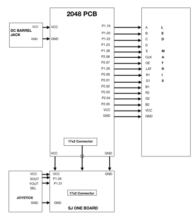
| − | [[File: | + | [[File:2048_ledmatrix_2.jpg|600px|thumb|left|LED Matrix Schematic]] |
| − | |||
| − | |||
| − | |||
| − | |||
| − | |||
</td> | </td> | ||
</tr> | </tr> | ||
| Line 282: | Line 280: | ||
</center> | </center> | ||
| − | === '''Hardware Design''' === | + | A 64x64 RGB LED Matrix Panel is used as a display. It has 4096 full-color RGB LEDs. Each LED can be independently addressed and controlled. It requires at 13 digital GPIOs to control the LED matrix. The led matrix has 2 IDC connectors DATA_IN and DATA_OUT on the back, we can cascade multiple panels and make a huge screen together. The LED display is constructed using a decoder to decode address rows. A 64 bit Shift register should be clocked for enabling the color. When the row is low we need to select which all pixels in the column are to be configured with the required color. This is done by clocking the 64Bit shift register. There are 6 64Bit registers each for R1 R2 B1 B2 G1 G2. A single clock is interfaced to all these 6 64bit shift registers. So at once we shift and fill the required color for the column display. Once the clocking and shifting the register is completed we need to latch this data to the register. The register data is sent out to all the row lines and that Row line which is pulled low by the decoder will receive this data and corresponding pixels are turned on. |
| + | |||
| + | RGB LED matrix pins: | ||
| + | {| class="wikitable" | ||
| + | |- | ||
| + | ! align="center"|S.NO | ||
| + | ! align="center"|RGB LED pins | ||
| + | ! align="center"|Function | ||
| + | |- | ||
| + | | scope="row" align="center"|1 | ||
| + | | scope="row" align="center"|R1 | ||
| + | | scope="row" align="center"|High R data | ||
| + | |- | ||
| + | | scope="row" align="center"|2 | ||
| + | | scope="row" align="center"|G1 | ||
| + | | scope="row" align="center"|High G data | ||
| + | |- | ||
| + | | scope="row" align="center"|3 | ||
| + | | scope="row" align="center"|B1 | ||
| + | | scope="row" align="center"|High B data | ||
| + | |- | ||
| + | | scope="row" align="center"|4 | ||
| + | | scope="row" align="center"|R2 | ||
| + | | scope="row" align="center"|Low R data | ||
| + | |- | ||
| + | | scope="row" align="center"|5 | ||
| + | | scope="row" align="center"|G2 | ||
| + | | scope="row" align="center"|Low G data | ||
| + | |- | ||
| + | | scope="row" align="center"|6 | ||
| + | | scope="row" align="center"|B2 | ||
| + | | scope="row" align="center"|Low B data | ||
| + | |- | ||
| + | | scope="row" align="center"|7 | ||
| + | | scope="row" align="center"|A | ||
| + | | scope="row" align="center"|Row select A | ||
| + | |- | ||
| + | | scope="row" align="center"|8 | ||
| + | | scope="row" align="center"|B | ||
| + | | scope="row" align="center"|Row select B | ||
| + | |- | ||
| + | | scope="row" align="center"|9 | ||
| + | | scope="row" align="center"|C | ||
| + | | scope="row" align="center"|Row select C | ||
| + | |- | ||
| + | | scope="row" align="center"|10 | ||
| + | | scope="row" align="center"|D | ||
| + | | scope="row" align="center"|Row select D | ||
| + | |- | ||
| + | |- | ||
| + | | scope="row" align="center"|11 | ||
| + | | scope="row" align="center"|E | ||
| + | | scope="row" align="center"|Row select E | ||
| + | |- | ||
| + | |||
| + | | scope="row" align="center"|12 | ||
| + | | scope="row" align="center"|CLK | ||
| + | | scope="row" align="center"|Clock signal. | ||
| + | |- | ||
| + | | scope="row" align="center"|13 | ||
| + | | scope="row" align="center"|OE | ||
| + | | scope="row" align="center"|Output enables to cascade LED panel. | ||
| + | |- | ||
| + | | scope="row" align="center"|14 | ||
| + | | scope="row" align="center"|LAT | ||
| + | | scope="row" align="center"|Latch denotes the end of data. | ||
| + | |- | ||
| + | | scope="row" align="center"|15 | ||
| + | | scope="row" align="center"|VCC | ||
| + | | scope="row" align="center"|5V | ||
| + | |- | ||
| + | | scope="row" align="center"|16 | ||
| + | | scope="row" align="center"|GND | ||
| + | | scope="row" align="center"|GND | ||
| + | |- | ||
| + | |} | ||
| + | |||
| + | ===== Row Selection ===== | ||
| + | |||
| + | The RGB matrix has a 5:32 decoder. This decoder takes 5 bits as input and decodes the corresponding row to be kept low. There are five address inputs to the display marked A, B, C, D and E. Based on the truth table, only one input is active (low) at a time. The outputs of the decoder are connected to a P-Channel MOSFET because the decoder itself can only handle low currents and cannot drive a row of LEDs directly. The P-Channel MOSFET provides the high current needed to drive a row of LEDs. | ||
| + | The decoder outputs are shared between every 32 outputs. Since, the 5-to-32 address decoder select rows in parallel like 1 and 33, 2 and 34, repeating that pattern until row 32 and 64. | ||
| + | |||
| + | ===== Column Selection ===== | ||
| + | |||
| + | The column data is stored in a 64-bit serial-in, a parallel-out shift register. The shift register is designed to work with LEDs and implements a constant-current system that ensures the LED brightness remains uniform. R1 G1 B1 is used for configuring the color for the top half of the display and R2 G2 B2 for the bottom half of the display. For 64 rows using with 32 outputs of the decoder, we must have unique data for each row pair. When Row 1 and Row 33 are selected, we must provide each row with unique data. This forces us to use two different shift registers for each row pair, an upper register, and a lower register. Because of this, the display is divided into an upper half and a lower half. The data is shifted into the top half via the R1, G1 and B1 signals on the connector. The bottom halves data is supplied by the R2, G2 and B2 signals on the connector. Then, since our display is 64 pixels wide, we use 64-bit shift registers to hold all 64 bits of pixel data for a single row. Each half of the display is controlled by 3 shift registers, one for each color. First, Row 1 and Row 33 are selected then 64 bits of data are shifted into each color’s shift register (R1, G1, B1), and then latched. At the same time, 64 bits of data are also shifted into each color’s shift register for the bottom half (R2, G2, B2), and then latched. The process repeats 31 more times, each time incrementing the rows are selected until every line has been updated. | ||
| + | |||
| + | In order to display something on the LED panels the following steps need to be performed by the driver | ||
| + | * Shift the pixel data for row 1 into the top column drivers and the pixel data for row 33 into the bottom column drivers using the R1, G1, B1, R2, G2, and B2 data inputs and the SCLK shift clock signal. | ||
| + | * Clear the blanking signal to blank the display. | ||
| + | * Set the address input to 1. | ||
| + | * Latch the contents of the column driver's shift registers to the output registers using the LATCH signal. | ||
| + | * Make the blanking signal high to display rows 1 and 33. | ||
| + | * Repeat the process for each of the pairs of rows in the display for 31 times. | ||
| + | |||
| + | ===== Specifications: ===== | ||
| + | The LED display used in our project is a 64*64 pixel panel with a pixel pitch of 3mm. More specifications are tabulated. | ||
| + | * Operating voltage: DC 5V | ||
| + | * Average power consumption: <500W/㎡ | ||
| + | * Maxim Power Consumption: <1000w/㎡ | ||
| + | * Pixel: 64x64=4096 | ||
| + | * Level of viewing Angle: ≧160° | ||
| + | * Control mode: Synchronous control | ||
| + | * Drive mode: 1/16 scan rate | ||
| + | * Repetition frequency: ≧60Hz | ||
| + | * White Balance Brightness: ≧1200cd/㎡ | ||
| + | * Refresh frequency : ≧300Hz | ||
| + | * MTTF: ≧5000 hours | ||
| + | * Service Life: 75000~100000 hours | ||
| + | * Pixel pitch: 3mm | ||
| + | * Thickness: 11mm | ||
| + | |||
| + | ==='''Hardware Design'''=== | ||
| + | |||
==== Printed Circuit Board (PCB) ==== | ==== Printed Circuit Board (PCB) ==== | ||
| Line 655: | Line 765: | ||
===Testing === | ===Testing === | ||
| + | Testing plays a crucial role in the development of a project. Testing is used at key checkpoints in the overall process to determine whether objectives are being met. | ||
| + | |||
| + | ====Display Driver==== | ||
| + | |||
| + | * We tested our driver by trying to control each pixel and each row. | ||
| + | * We also tested it for color control by dumping same data in different colors. | ||
| + | * After a lot of testing we realized that delay between writing two rows is very important. So after some R&D we set it to 80us which gave us the brightness needed. | ||
| + | |||
| + | ====Display Application==== | ||
| + | * We designed three different fonts. So, we tested display application by printing every digit on the display and made corrections to font designs. | ||
| + | |||
| + | ====Game Logic==== | ||
| + | * Scope of game logic is to only update a 4x4 matrix. So, we tested and verified our game logic part by printing values on our linux console. | ||
| + | |||
| + | ====Tasks==== | ||
| + | * Although we have only two tasks, we realized that the priority levels really mattered a lot. So, we tested code by changing priority and finally fixed on one combination. | ||
=== Challenges === | === Challenges === | ||
| − | + | Unlike our initial assumption, our game logic was not really complex to implement. But some other aspects of the project really were. | |
| − | + | ||
| + | ====Working with LED Matrix Display==== | ||
| + | Because of unavailability of data sheet for the display, we had to do a lot of experiments to understand how it works. There were still some surprises almost until the end. | ||
| + | Writing display application on top of the driver was also challenging, since we had to fit all our data in 64x64 pixels. So, we had to be thrifty with printing anything on display. | ||
| + | ====Finding the right components for PCB==== | ||
| + | We did not know that finding components will also pose a challenge, before this project. We got all the right components just a couple of days before the final demo. | ||
| − | + | ===Bugs=== | |
| + | ====Multiple Input Option Does Not Work==== | ||
| + | We wrote code for Accelerometer application. We also used it to play. Playing with accelerometer works fine. But we could not complete implementing start screen, with options to select input type. | ||
| − | === | + | ====Reading Continuous Input==== |
| − | + | Holding joystick at same position will read the input continuously, which should not be the case. This can be solved by proper delay in sampling input and maintaining previous state of the input and comparing with current. | |
== Conclusion == | == Conclusion == | ||
| − | + | We successfully designed and implemented the classic 2048 game which is controlled by a joystick/accelerometer. This project was a success both in terms of output and learnings. It provided us an exposure of working with RGB LED matrix, joystick, and accelerometer. We learned to write a driver for an RGB LED matrix. It helped us utilize the knowledge of FreeRTOS which we gained through the CMPE-244 class. | |
=== Project Video === | === Project Video === | ||
| − | + | [https://www.youtube.com/watch?v=ZYkCdsC31NA 2048 YouTube Video] | |
=== Project Source Code === | === Project Source Code === | ||
| − | * [https://github.com/vishalsjsu/2048_Game 2048-Game] | + | * [https://github.com/vishalsjsu/2048_Game GitHub-2048-Game] |
== References == | == References == | ||
| Line 685: | Line 818: | ||
[2] [https://en.wikipedia.org/wiki/2048_(video_game) 2048_Game] | [2] [https://en.wikipedia.org/wiki/2048_(video_game) 2048_Game] | ||
| − | [3] CMPE 244 Lecture notes and assignments from Preetpal Kang, Computer Engineering, San Jose State University. Aug-Dec 2018. | + | [3] CMPE 244 Lecture notes and assignments from Prof. Preetpal Kang, Computer Engineering, San Jose State University. Aug-Dec 2018. |
[4] [https://www.adafruit.com/product/3649 Adafruit 64x64 RGB LED Matrix] | [4] [https://www.adafruit.com/product/3649 Adafruit 64x64 RGB LED Matrix] | ||
| − | |||
| − | |||
| − | |||
| − | |||
| − | |||
| − | |||
| − | |||
| − | |||
Latest revision as of 19:20, 6 February 2019
Contents
2048
Abstract
2048 is a game having a grid of numbered tiles (i.e., a power of 2) to combine them to create a tile with the number 2048. It is usually played on a 4x4 grid with tiles that slide smoothly when a player moves them towards the right, left, up or down. Every time a new tile will randomly appear in an empty spot on the display with a value of either 2 or 4. If two tiles of the same number collide then they will merge into one tile with a value of the sum of those two tiles. The game continues until no merge is possible. The game uses RGB LED matrix to display the 4x4 game grid and the scores. The player is given a choice to choose thumb joystick or an onboard accelerometer to give direction inputs; left, right, up and down. The Game Logic and the display are updated using FreeRTOS tasks.
Objectives & Introduction
The primary goal of this project is to develop 2048 game with FreeRTOS using SJone Board and to drive the LED matrix to display the 4x4 game grid. The game's objective is to slide numbered tiles on a grid to combine them to create a tile with the number 2048. The player is given the choice to choose between the thumb joystick and an onboard accelerometer to give directions.
Objectives:
- Write drivers to display number grid, score on the RGB LED matrix and update the display continuously.
- Write drivers to give directions from the input devices (joystick/accelerometer).
- Implement game algorithm for movement of blocks in real-time, generate a random tile (2 or 4) and update scores.
- Implement game over logic once the grid is full and no merges are possible.
- Create FeeRTOS tasks for display and game logic and understand the communication and synchronization between them.
Team Members & Responsibilties
- Deepak Shivani
- Hardware Design
- LED Display Drivers
- PCB Design
- Navyashree Chandraiah
- Game Logic
- PCB Design
- Sai Kiran Duggineni
- LED Display Application
- Shrusti Shashidhar
- Joystick Drivers
- Game Logic
- Vishal Yarabandi
- LED Display Drivers
- Wiki Schedule
Schedule
| Week# | Start Date | Task | Status | Completion Date |
|---|---|---|---|---|
| 1 | 09/18 |
|
|
|
| 2 | 10/09 |
|
|
|
| 3 | 10/16 |
|
|
|
| 4 | 10/23 |
|
|
|
| 5 | 10/30 |
|
|
|
| 6 | 11/06 |
|
|
|
| 7 | 11/13 |
|
|
|
| 8 | 11/20 |
|
|
|
| 9 | 11/27 |
|
|
|
| 10 | 12/03 |
|
|
|
Parts List & Cost
| Component | Cost | Quantity | Seller |
|---|---|---|---|
| SJOne Board | $80 | 1 | Preetpal Kang |
| Adafruit RGB (64x64) LED Matrix Display | $74.95 | 1 | Adafruit |
| Adafruit Analog 2-axis thumb Joystick | $10.18 | 1 | Amazon |
| 5V/4A Power Supply Adapter | $15.95 | 1 | Amazon |
| 34 Pin Flat Ribbon Cable | $6.12 | 1 | Amazon |
| PCB | $23 | 5 | PCBWay |
| DC barrel Jack | $6.70 | 1 | Amazon |
| Terminal Blocks | $8.70 | 1 | Amazon |
| Sliding Switches | $5.35 | 1 | Amazon |
Design & Implementation
Hardware Interface
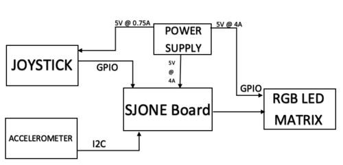
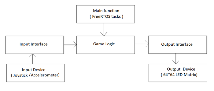
The figure below shows the basic block diagram for our game 2048 implemented on a 64x64 RGB LED matrix display.
Joystick
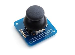
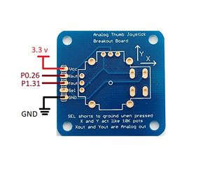
A joystick is an input device consisting of a stick that moves on a base and reports its angle or direction to the device it is controlling. In this project, we are using a joystick to give the control input. The joystick controls our game grid by moving it up, down, left and right based on the respective input fed to the microcontroller. This gives the access to the player to make the desired move and achieve the number 2048. The Joystick also has a select functionality which is nothing but a digital signal that helps the player to give a high/low signal from the joystick. In this project, we are using the Adafruit’s analog 2-axis thumb joystick (ADA512). It is an analog joystick with 2 analog pins and 1 digital pin for the select functionality. The joystick also consists of a VCC and GND pin for the power supply. The 2 analog pins give the output value corresponding to direction based on the movement of the joystick. The joystick is functional with any voltage up to 5V with 1mA current draw.
Accelerometer
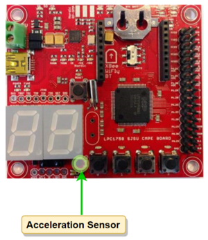
An accelerometer is an electromechanical device that will measure acceleration forces. These forces may be static, like the constant force of gravity pulling at your feet, or they could be dynamic - caused by tilting the accelerometer. We are using an accelerometer that is available on the SJOne Board just to give the player the choice of controls. The accelerometer gives the orientation of the board when it is moved in up, down, left and right directions which further controls the grid movement based on the 3-axis output value. In this project we are using the MMA8452Q is a smart low-power, three-axis, capacitive micromachined accelerometer with 12 bits of resolution. It is interfaced using the I2C digital output interface (operates to 2.25 MHz with 4.7 kΩ pull-up resistor) and works on up to 3.6V of supply voltage with 6uA – 165uA current consumption.
RGB LED Matrix
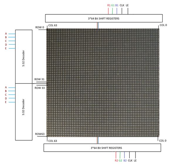
A 64x64 RGB LED Matrix Panel is used as a display. It has 4096 full-color RGB LEDs. Each LED can be independently addressed and controlled. It requires at 13 digital GPIOs to control the LED matrix. The led matrix has 2 IDC connectors DATA_IN and DATA_OUT on the back, we can cascade multiple panels and make a huge screen together. The LED display is constructed using a decoder to decode address rows. A 64 bit Shift register should be clocked for enabling the color. When the row is low we need to select which all pixels in the column are to be configured with the required color. This is done by clocking the 64Bit shift register. There are 6 64Bit registers each for R1 R2 B1 B2 G1 G2. A single clock is interfaced to all these 6 64bit shift registers. So at once we shift and fill the required color for the column display. Once the clocking and shifting the register is completed we need to latch this data to the register. The register data is sent out to all the row lines and that Row line which is pulled low by the decoder will receive this data and corresponding pixels are turned on.
RGB LED matrix pins:
| S.NO | RGB LED pins | Function |
|---|---|---|
| 1 | R1 | High R data |
| 2 | G1 | High G data |
| 3 | B1 | High B data |
| 4 | R2 | Low R data |
| 5 | G2 | Low G data |
| 6 | B2 | Low B data |
| 7 | A | Row select A |
| 8 | B | Row select B |
| 9 | C | Row select C |
| 10 | D | Row select D |
| 11 | E | Row select E |
| 12 | CLK | Clock signal. |
| 13 | OE | Output enables to cascade LED panel. |
| 14 | LAT | Latch denotes the end of data. |
| 15 | VCC | 5V |
| 16 | GND | GND |
Row Selection
The RGB matrix has a 5:32 decoder. This decoder takes 5 bits as input and decodes the corresponding row to be kept low. There are five address inputs to the display marked A, B, C, D and E. Based on the truth table, only one input is active (low) at a time. The outputs of the decoder are connected to a P-Channel MOSFET because the decoder itself can only handle low currents and cannot drive a row of LEDs directly. The P-Channel MOSFET provides the high current needed to drive a row of LEDs. The decoder outputs are shared between every 32 outputs. Since, the 5-to-32 address decoder select rows in parallel like 1 and 33, 2 and 34, repeating that pattern until row 32 and 64.
Column Selection
The column data is stored in a 64-bit serial-in, a parallel-out shift register. The shift register is designed to work with LEDs and implements a constant-current system that ensures the LED brightness remains uniform. R1 G1 B1 is used for configuring the color for the top half of the display and R2 G2 B2 for the bottom half of the display. For 64 rows using with 32 outputs of the decoder, we must have unique data for each row pair. When Row 1 and Row 33 are selected, we must provide each row with unique data. This forces us to use two different shift registers for each row pair, an upper register, and a lower register. Because of this, the display is divided into an upper half and a lower half. The data is shifted into the top half via the R1, G1 and B1 signals on the connector. The bottom halves data is supplied by the R2, G2 and B2 signals on the connector. Then, since our display is 64 pixels wide, we use 64-bit shift registers to hold all 64 bits of pixel data for a single row. Each half of the display is controlled by 3 shift registers, one for each color. First, Row 1 and Row 33 are selected then 64 bits of data are shifted into each color’s shift register (R1, G1, B1), and then latched. At the same time, 64 bits of data are also shifted into each color’s shift register for the bottom half (R2, G2, B2), and then latched. The process repeats 31 more times, each time incrementing the rows are selected until every line has been updated.
In order to display something on the LED panels the following steps need to be performed by the driver
- Shift the pixel data for row 1 into the top column drivers and the pixel data for row 33 into the bottom column drivers using the R1, G1, B1, R2, G2, and B2 data inputs and the SCLK shift clock signal.
- Clear the blanking signal to blank the display.
- Set the address input to 1.
- Latch the contents of the column driver's shift registers to the output registers using the LATCH signal.
- Make the blanking signal high to display rows 1 and 33.
- Repeat the process for each of the pairs of rows in the display for 31 times.
Specifications:
The LED display used in our project is a 64*64 pixel panel with a pixel pitch of 3mm. More specifications are tabulated.
- Operating voltage: DC 5V
- Average power consumption: <500W/㎡
- Maxim Power Consumption: <1000w/㎡
- Pixel: 64x64=4096
- Level of viewing Angle: ≧160°
- Control mode: Synchronous control
- Drive mode: 1/16 scan rate
- Repetition frequency: ≧60Hz
- White Balance Brightness: ≧1200cd/㎡
- Refresh frequency : ≧300Hz
- MTTF: ≧5000 hours
- Service Life: 75000~100000 hours
- Pixel pitch: 3mm
- Thickness: 11mm
Hardware Design
Printed Circuit Board (PCB)
The PCB was designed using the free version of AUTODESK Eagle v9.2.0. We used the preinstalled libraries in the Eagle software and also imported Sparkfun libraries for the PCB components. The PCB constitutes the power supply circuit and all the internal connections between the devices for this project. The power supply for the joystick, SJOne Board and the RGB LED matrix display comes from this PCB. We designed a 2-layer PCB which is capable of supplying 5V output voltage at different current ratings.
PCB Schematic
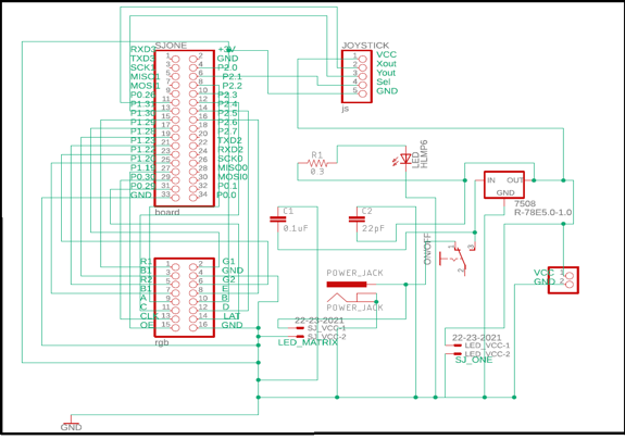
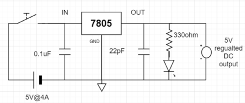
The PCB consists of a 2x17 pin header to replicate the pins of the SJOne board, it also consists of a 2x8 pin header for the RGB LED matrix display and a 5 pin header for the joystick. The circuit is controlled by the main sliding switch which gives the project an ON/OFF functionality. The circuit gets the main power supply from a 5V, 4A DC adapter which is connected to a DC barrel jack mounted on the PCB. The PCB provides the desired voltages to the SJOne board, LED display and joystick using a combination of resistors and capacitors with 7805 voltage regulator IC.
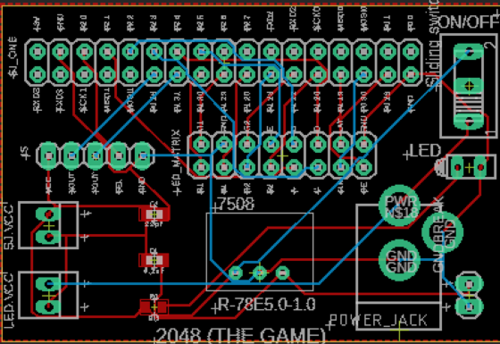
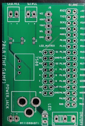
Board Layout
EAGLE’s board designer is where the dimensions of the board come into play. The parts are arranged and connected by copper traces. In the board editor, the conceptual, idealized schematic we have designed becomes a precisely dimensioned and routed PCB.
| Sl.No | Components | Specifications | Quantity |
|---|---|---|---|
| 1 | 2x17 Pin header | 0.5 in | 1 |
| 2 | 2x8 Pin header | 0.5 in | 1 |
| 3 | 1x5 Pin header | 0.5 in | 1 |
| 4 | DC Barrel Jack | 2.1mm x 5.5mm | 1 |
| 5 | Sliding Switch | 5 mm | 1 |
| 6 | 2 pin Terminal blocks | 2.54 mm | 2 |
| 7 | 1x2 Pin header | 0.5 in | 1 |
| 8 | IC 7805 | 5mm | 1 |
| 9 | Resistor | 2mm | 1 |
| 10 | Capacitors | 2mm | 2 |
| 11 | Indicator LED | 5mm | 1 |
Software Design
There are four modules in the software design: Game Logic, Output Interface, Input Interface and the FreeRTOS tasks. When the board boots up, user is given option to select the Input type (Joystick/Accelerometer). An application interface to the selected input device is given to the Game Logic. Two FreeRTOS tasks are created to run the Game Logic and update the display. Game Logic manipulates the game grid, by taking direction as the input through the Input Interface. It invokes the Display Application to dump updated game grid onto the LED Matrix display.
Implementation
Display Driver
Purpose of the driver is to give capability to control the device. The LED Matrix display is interfaced over the GPIO pins on the SJOne board. So, the driver for LED matrix display is internally using the GPIO drivers. LED matrix display driver configures all the GPIO pins as output pins at start and sets their values to default. It gives capability to control every pixel on the display. It keeps a frame buffer in its memory and writes application data on the buffer. The main code creates a task to dump the frame buffer onto the Display Device.
typedef struct {
    LPC1758_GPIO_Type A;
    LPC1758_GPIO_Type B;
    LPC1758_GPIO_Type C;
    LPC1758_GPIO_Type D;
    LPC1758_GPIO_Type E;

    LPC1758_GPIO_Type latch;
    LPC1758_GPIO_Type oe;
    LPC1758_GPIO_Type clk;

    LPC1758_GPIO_Type r1;
    LPC1758_GPIO_Type g1;
    LPC1758_GPIO_Type b1;
    LPC1758_GPIO_Type r2;
    LPC1758_GPIO_Type g2;
    LPC1758_GPIO_Type b2;
}LEDMatrixDisplayPincon;

enum Color { //RGB (000 => Off)
    Off,
    Blue,
    Green,
    Cyan,
    Red,
    Pink,
    Lime,
    White
};

enum ColorPlane {
    RedPlane,
    GreenPlane,
    BluePlane
};

class LEDMatrix : public SingletonTemplate<LEDMatrix> {
private:
    friend class SingletonTemplate<LEDMatrix>;
    GPIO *A, *B, *C, *D, *E, *latch, *oe, *clk, *r1, *g1, *b1, *r2, *g2, *b2;
    uint64_t farmeBuffer[64][3];  //64 rows of 3 64 bit integers, for RGB color control of each row

public:
    void init(LEDMatrixDisplayPincon &);
    void enableDisplay();
    void disableDisplay();
    void enableLatch();
    void disableLatch();
    void clearFrameBuffer();
    void updateDisplay();
    void selectRow(int row);
    void clearPixel(int row, int col);
    void setPixel(int row, int col, Color color);
    void setRowData(int row, Color color, uint64_t = 0xFFFFFFFFFFFFFFFF);
    void setRowDataRaw(int row, ColorPlane plane, uint64_t data); //If you know what you're doing!
    void fillFrameBuffer(uint64_t data, Color color);
};
Display Application
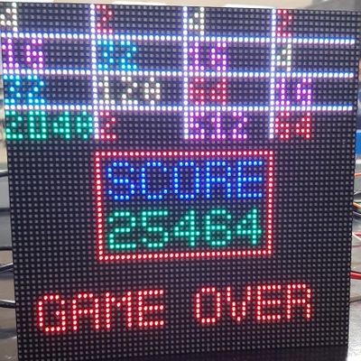
The display application is the middle-ware between the Game Logic and the Display Drivers. It is responsible for translating the 4x4 matrix of integers into the 64x64 data to display on the LED matrix. The display application refers to the digit designs that are in a lookup table and sets or clears the pixels according to this lookup table. There are two different font sizes in this application; One which uses 5x3 matrix of pixels and another, which is relatively bigger, using 7x5 matrix of pixels. The numbers in the grid are displayed using the smaller font size and all the remaining data is displayed in the bigger font.
using namespace std;
typedef std::map<int, Color> ColorMap;

void getDigitsFromNumber(int num, std::vector<int>&digits);

enum FontType {
    SmallFont,
    BigFont
};

class DisplayApp {
private:
    LEDMatrix display = LEDMatrix::getInstance();

public:
    void initDisplay(LEDMatrixDisplayPincon &pincon);
    void updateDisplay();
    void displayGrid(int (*grid)[4], ColorMap &colorMap);
    void displayGridBorders(Color color);
    void displayNumber(int num, Color color, int start_row, int start_pixel, FontType font);
    void displayDigit(int digit, Color color, int start_row, int start_pixel, FontType font);
    void displayString(string s, Color color, int start_row, int start_pixel);
    void displayCharacter(char c, Color color, int start_row, int start_pixel);
    void displayNumberSmallFont(int num, Color color, int start_row, int start_pixel);
    void displayNumberBigFont(int num, Color color, int start_row, int start_pixel);
    void displayDigitSmallFont(int digit, Color color, int start_row, int start_pixel);
    void displayDigitBigFont(int digit, Color color, int start_row, int start_pixel);
    void drawBox(int xMin, int yMin, int xMax, int yMax, Color color);
};
Game Logic
The game logic has interface to the input and output devices. It takes direction as the input from the input device and runs move logic on the game grid. The game algorithm iterates over the 4x4 matrix of integers and merges tiles if there are two same value tiles, adjacent to each other in the direction of the input. The game score is cumulative sum of all the merges that happen in the grid. Once the game grid and scores are updated, display application is used to update the screen.
class Game {
private:
    int grid[4][4];
    int score;
    bool moved;
    DisplayApp *displayApp;   //Output Interface
    Input *input;             //Input Interface

public:
    Game(DisplayApp *displayApp, Input *gameInput);
    void updateScreen();
    void run();            //Takes direction input and calls moveTiles() and invokes updateScreen()
    void generateNewTile();
    bool moveTiles(Direction inputDirection);
    void displayScore();
    void rotate();
    void moveUp();
    void moveDown();
    void moveLeft();
    void moveRight();
    bool gridIsFull();
    bool anyPairsPresent();
    bool gameEnded();
};
Input Interface
The input for this game is just the direction. So, we can use any device that can give us the direction input. We are letting the user chose between the on-board accelerometer and a thumb joystick. In future we might also want to update the project by integrating a different input device such as touchscreen. But, adding a different device must not change anything in the Game Logic class. This idea can be implemented using an interface class, which defines the input interface. The application code for each of the input devices must implement this interface. This way game logic will only talk to the interface and not to the input device applications directly.
enum Direction {
        Still,
        Up,
        Down,
        Right,
        Left
};

class Input {
public:
    virtual Direction getDirection() = 0;
    virtual bool selectPressed() = 0;
};
Joystick Application
Joystick application implements the Input interface class. The Joystick driver gives out analog X-axis and Y-axis values when it is moved. Joystick application takes these analog values and maps them to a direction value.
class JoystickApp : public Input {
private:
    Joystick *JS;

public:
    JoystickApp(Pin pinX, Pin pinY);
    Direction getDirection();
    bool selectPressed();
    virtual ~JoystickApp();
};
Accelerometer Application
Accelerometer application implements the Input interface class. We are using the existing Accelerometer drivers from the SJOne development package. The Accelerometer driver gives out analog X-axis and Y-axis values when it is moved. The accelerometer application takes these analog values and maps them to a direction value.
class AccelerometerApp : public Input {
private:
    Acceleration_Sensor acc_sense = Acceleration_Sensor::getInstance();

public:
    AccelerometerApp() {}
    Direction getDirection();
    bool selectPressed();
    virtual ~AccelerometerApp();
};
Joystick Driver
Thumb Joystick is an analog device. It gives the analog X-axis and Y-axis values whenever it is moved. So, input from joystick is read through the ADC channels of lpc1758. We are using the existing ADC driver available in our SJOne development package and building the joystick driver on top of it. Select signal in the Joystick is currently not being used.
enum Pin {
        k0_25,       // AD0.2 <-- Light Sensor -->
        k0_26,       // AD0.3
        k1_30,       // AD0.4
        k1_31,       // AD0.5
};

class Joystick {
private:
    uint8_t channelX, channelY;

public:
    Joystick(Pin pinX, Pin pinY);
    void selectPin(Pin pin);
    uint8_t getChannelNumberOfPin(Pin pin);
    uint16_t getX();
    uint16_t getY();
};
FreeRTOS Tasks
The entire application being very simple, does not need too many tasks. The game grid is updated only when there is any input from the user. So, there must be a task that can sample the input at regular intervals and run the game algorithm based on the input. Display has to be updated very frequently for the output to seem stable on the display. We could use either a Repetitive Software Interrupt or a task that runs at right frequency. We have chosen to use a task for updating display since an interrupt based design would be less predictable.
The main code initiates the display and takes user selection of input device. It then creates tasks to start the game.
displayApp.initDisplay(displayPincon);
xTaskCreate(displayTask, "Display", STACK_SIZE, 0, PRIORITY_HIGH, NULL);
xTaskCreate(gameLogicTask, "Game", STACK_SIZE, 0, PRIORITY_MEDIUM, NULL);

void displayTask(void *p)
{
    while(1) {
        displayApp.updateDisplay();
        vTaskDelay(7);
    }
}

void gameLogicTask(void *p)
{
    game.generateNewTile();
    game.generateNewTile();
    while(1) {
        game.run();
        vTaskDelay(150);
    }
}
Testing & Technical Challenges
Testing
Testing plays a crucial role in the development of a project. Testing is used at key checkpoints in the overall process to determine whether objectives are being met.
Display Driver
- We tested our driver by trying to control each pixel and each row.
- We also tested it for color control by dumping same data in different colors.
- After a lot of testing we realized that delay between writing two rows is very important. So after some R&D we set it to 80us which gave us the brightness needed.
Display Application
- We designed three different fonts. So, we tested display application by printing every digit on the display and made corrections to font designs.
Game Logic
- Scope of game logic is to only update a 4x4 matrix. So, we tested and verified our game logic part by printing values on our linux console.
Tasks
- Although we have only two tasks, we realized that the priority levels really mattered a lot. So, we tested code by changing priority and finally fixed on one combination.
Challenges
Unlike our initial assumption, our game logic was not really complex to implement. But some other aspects of the project really were.
Working with LED Matrix Display
Because of unavailability of data sheet for the display, we had to do a lot of experiments to understand how it works. There were still some surprises almost until the end. Writing display application on top of the driver was also challenging, since we had to fit all our data in 64x64 pixels. So, we had to be thrifty with printing anything on display.
Finding the right components for PCB
We did not know that finding components will also pose a challenge, before this project. We got all the right components just a couple of days before the final demo.
Bugs
Multiple Input Option Does Not Work
We wrote code for Accelerometer application. We also used it to play. Playing with accelerometer works fine. But we could not complete implementing start screen, with options to select input type.
Reading Continuous Input
Holding joystick at same position will read the input continuously, which should not be the case. This can be solved by proper delay in sampling input and maintaining previous state of the input and comparing with current.
Conclusion
We successfully designed and implemented the classic 2048 game which is controlled by a joystick/accelerometer. This project was a success both in terms of output and learnings. It provided us an exposure of working with RGB LED matrix, joystick, and accelerometer. We learned to write a driver for an RGB LED matrix. It helped us utilize the knowledge of FreeRTOS which we gained through the CMPE-244 class.
Project Video
Project Source Code
References
Acknowledgement
We would like to thank our professor, Preetpal Kang for all his assistance and inspirational lectures. We had a great learning experience during the project and throughout the coursework. We would also like to thank the ISA team for their valuable advice and constructive feedback.
References Used
[2] 2048_Game
[3] CMPE 244 Lecture notes and assignments from Prof. Preetpal Kang, Computer Engineering, San Jose State University. Aug-Dec 2018.
