Difference between revisions of "F18: baem geim"
Proj user10 (talk | contribs) (→1.3 Game Over condition) |
Proj user4 (talk | contribs) (→Hardware Design) |
||
| (101 intermediate revisions by 2 users not shown) | |||
| Line 1: | Line 1: | ||
| − | + | [[File:snakepixel.jpg|thumb|900x600px|right|Snake]] | |
| − | + | ||
| − | |||
| − | |||
| − | |||
| − | |||
| − | |||
| − | |||
| − | |||
| − | |||
| − | |||
== Project Title == | == Project Title == | ||
'''baem geim - Snake Game Reborn''' | '''baem geim - Snake Game Reborn''' | ||
| Line 16: | Line 7: | ||
== Abstract == | == Abstract == | ||
| − | baem geim is a revived, | + | baem geim is a revived, amusing Snake Game where a player maneuvers a line which grows in length, with the line itself and wall as obstacle. The concept originated in the 1976 arcade game Blockade, and the ease of implementing snake has led to hundreds of versions for many platforms. This is a new version of snake game which we have developed. The player controls the dot using handheld joystick. As it moves forward, it leaves a trail behind, resembling a moving snake. The snake movement is visually displayed in real time on a 32*32 LED Matrix. The player attempts to eat randomly generated dots as fruits by running into it with the head of the snake. Each fruit eaten increases the length of the snake and controlling it becomes progressively difficult. The player loses the game if the snake runs into itself or hits the screen border. |
| − | The game is designed using two SJone LPC1758 microcontroller boards one each to drive LED Matrix and Joystick module respectively. They communicate wirelessly through RF Nordic transceiver. | + | The game is designed using two SJone LPC1758 microcontroller boards one each to drive LED Matrix and Joystick module respectively. They communicate wirelessly through RF Nordic transceiver. An additional feature is the use of active buzzer for sound effects. |
== Objectives & Introduction == | == Objectives & Introduction == | ||
| Line 34: | Line 25: | ||
== Team Members & Responsibilities == | == Team Members & Responsibilities == | ||
| − | * '''[https://www.linkedin.com/in/bharath-vyas/ Bharath Vyas Balasubramanyam]''' | + | * '''[https://www.linkedin.com/in/bharath-vyas/ Bharath "Boa" Vyas Balasubramanyam]''' |
| − | ** Nordic Wireless Transmitter driver implementation and Driver for | + | ** Nordic Wireless Transmitter driver implementation and Driver for Joystick Module |
| − | * '''[https://www.linkedin.com/in/neeraj-dhavale-4ba651164/ Neeraj Dhavale]''' | + | * '''[https://www.linkedin.com/in/neeraj-dhavale-4ba651164/ Neeraj "Naag" Dhavale]''' |
** Driver for LED Matrix and Nordic Wireless Receiver Driver Implementation | ** Driver for LED Matrix and Nordic Wireless Receiver Driver Implementation | ||
| − | * '''[https://www.linkedin.com/in/sudarshan-aithal/ Sudarshan Aithal]''' | + | * '''[https://www.linkedin.com/in/sudarshan-aithal/ Sudarshan "Python" Aithal]''' |
** Design, Development and Implementation of Game Algorithm | ** Design, Development and Implementation of Game Algorithm | ||
| − | * '''[https://www.linkedin.com/in/vignesh-kumar-v/ Vignesh Kumar Venkateshwar]''' | + | * '''[https://www.linkedin.com/in/vignesh-kumar-v/ Vignesh "Viper" Kumar Venkateshwar]''' |
** PCB Design and Driver Implementation for Joystick Module | ** PCB Design and Driver Implementation for Joystick Module | ||
| Line 250: | Line 241: | ||
* Test the fabricated PCB. | * Test the fabricated PCB. | ||
| | | | ||
| − | * | + | * Completed |
| − | * | + | * Completed |
| | | | ||
| − | * | + | * 12/05/18 |
| − | * | + | * 12/07/18 |
| | | | ||
|- | |- | ||
| Line 263: | Line 254: | ||
* Final testing of the game and resolve flaws if any | * Final testing of the game and resolve flaws if any | ||
| | | | ||
| − | * | + | * Completed |
| + | | | ||
| + | * 12/14/2018 | ||
| + | | | ||
| + | |- | ||
| + | |||
| + | ! scope="row"| 12 | ||
| + | | 12/08/18 | ||
| + | | | ||
| + | * Report Completion and Project Demonstration | ||
| + | | | ||
| + | * Completed | ||
| | | | ||
| − | * | + | * 12/19/18 |
| | | | ||
|- | |- | ||
| Line 325: | Line 327: | ||
| 5 | | 5 | ||
| $19.36 | | $19.36 | ||
| + | |- | ||
| + | |||
| + | ! scope="row"| 8 | ||
| + | | PCB Components | ||
| + | |[https://www.digikey.com/ Digikey] | ||
| + | | 5 | ||
| + | | $20.96 | ||
|- | |- | ||
! | ! | ||
| Line 330: | Line 339: | ||
!- | !- | ||
!- | !- | ||
| − | ! $ | + | ! $291.27 |
|} | |} | ||
| Line 336: | Line 345: | ||
=== Hardware Design === | === Hardware Design === | ||
| − | The Hardware design for baem geim involves the use of two SJone LPC1758 microcontroller boards, 32x32 RGB LED Matrix, Joystick module | + | |
| + | The design flow diagram of the project is shown below. | ||
| + | |||
| + | [[File:FlowDiagram.jpg|thumb|1000px|center|Design Flow Diagram]] <br> | ||
| + | |||
| + | The Hardware design for baem geim involves the use of two SJone LPC1758 microcontroller boards, 32x32 RGB LED Matrix, Joystick module, Nordic Wireless Transceiver and Active Buzzer as described below. Pin configuration information for integration with PCB and power source have been detailed. | ||
'''LED Matrix''' | '''LED Matrix''' | ||
| Line 346: | Line 360: | ||
On the PCB is 12 LED driver chips. These are like 74HC595s but they have 16 outputs and they are constant current. 16 outputs * 12 chips = 192 LEDs that can be controlled at once, and 64 * 3 (R G and B) = 192. So now the design comes together. We can have 192 outputs that can control one line at a time, with each of 192 R, G and B LEDs either on or off. The LPC1758 controller selects which section to currently draw (using A, B, C and D address pins - 4 bits can have 16 values). Once the address is set, the controller clocks out 192 bits of data (24 bytes) and latches it. Then it increments the address and clocks out another 192 bits, etc until it gets to address #15, then it sets the address back to #0. | On the PCB is 12 LED driver chips. These are like 74HC595s but they have 16 outputs and they are constant current. 16 outputs * 12 chips = 192 LEDs that can be controlled at once, and 64 * 3 (R G and B) = 192. So now the design comes together. We can have 192 outputs that can control one line at a time, with each of 192 R, G and B LEDs either on or off. The LPC1758 controller selects which section to currently draw (using A, B, C and D address pins - 4 bits can have 16 values). Once the address is set, the controller clocks out 192 bits of data (24 bytes) and latches it. Then it increments the address and clocks out another 192 bits, etc until it gets to address #15, then it sets the address back to #0. | ||
To light up an individual pixel, appropriate row value is loaded on to the address pins A,B,C & D, Clock is set out to traverse the row | To light up an individual pixel, appropriate row value is loaded on to the address pins A,B,C & D, Clock is set out to traverse the row | ||
| − | and when required pixel is reached, the latch is set high to turn ON the LED. | + | and when required pixel is reached, the latch is set high to turn ON the LED. |
| + | <br> | ||
| + | We have used the Adaafruit GFX libaray. In this library a 3D array of size 32*32*3= 3072 bytes is used. This 3D array basically represents the whole matrix with the three RGB values. Each function in the library takes the arguments of rows and columns and just makes the corresponding byte high in the matrix. The update display function is called in a repetitive interrupt function. This function loads travesses the 3D array and selects the appropriate row and loads the row using clk pin and finally latches in the value. <br> | ||
| + | Tip: Try to get drawpixel function working first. | ||
<br> | <br> | ||
<br> | <br> | ||
| Line 409: | Line 426: | ||
{| | {| | ||
|[[File:Layout.jpg|540px|thumb|left|Circuit Layout]] | |[[File:Layout.jpg|540px|thumb|left|Circuit Layout]] | ||
| − | |[[File:ManufacturedPCB.png|625px|thumb|right|PCB]] | + | |[[File:ManufacturedPCB.png|625px|thumb|right|Fabricated PCB]] |
|} | |} | ||
| Line 422: | Line 439: | ||
[[File:Game_flow.jpg|thumb|600px|center|Program Flow]] | [[File:Game_flow.jpg|thumb|600px|center|Program Flow]] | ||
| − | == Tasks == | + | === Tasks === |
| − | The game design consists of three independent tasks. | + | The game design consists of three independent tasks. First task polls on the user to enter the mode of the game (Normal/Arcade) and has been given the highest priority. The second task consists of draw pixel logic to generate the snake on the display console. The third task repeatedly polls for input from joystick which is used as reference for the snake motion. |
| − | ==== | + | ===== Logic Task ===== |
| − | Logic task calculates the snake body by using the snake's head as a reference. It also updates the row and column coordinates based on the | + | Logic task calculates the length of snake body by using the snake's head as a reference. It also updates the row and column coordinates based on the joystick task input. The spawning of ordinary fruit, bonus fruit and evil fruit along with conditions when any of these fruits are eaten by the snake are also handled in this task. Finally, it checks for the game over condition. |
| − | ===== | + | ===== Snake Body Generation ===== |
| − | This | + | This section of code is used to compute the coordinates of the snake's body. The X-Y coordinates of the snake's head at any particular instant is considered as a reference to generate the snake body. The current instance of snake head is copied to a register and a loop is run to the length of the snake body. Finally, coordinate values at every index is pushed back by one.<br> |
The code snippet for the snake's body generation is given below:<br> | The code snippet for the snake's body generation is given below:<br> | ||
| Line 448: | Line 465: | ||
</pre> | </pre> | ||
| − | ===== | + | ===== Snake Direction ===== |
| − | + | The direction of input for snake is obtained from Joystick. Based on the input, new coordinates are computed to determine next state direction of snake. Boundary conditions have been taken into consideration for Normal and Arcade mode.<br> | |
| − | + | '''Pseudo Code:''' | |
| − | |||
<pre> | <pre> | ||
switch (dir) | switch (dir) | ||
| Line 494: | Line 510: | ||
</pre> | </pre> | ||
| − | ===== | + | ===== Game Over Logic ===== |
| − | + | In arcade mode, if the snake's head collides either with itself or wall border, the gameover function is called which will print the score. In normal mode, gameover condition is determined only when the snake comes in contact with its own body.<br> | |
| − | '''Pseudo code''' | + | '''Pseudo code:''' |
<pre> | <pre> | ||
//Gameover condition for arcade mode | //Gameover condition for arcade mode | ||
| Line 524: | Line 540: | ||
</pre> | </pre> | ||
| − | ==== | + | ==== Draw Task ==== |
| − | Two LED matrix | + | Two LED matrix coordinates in a loop scale through all possible rows and columns, at an instance when LED Matrix coordinates equalizes with coordinates of snake head , the corresponding LED pixel(s) is/are turned ON and other pixels are turned OFF.<br> |
| − | '''Pseudo code''' | + | '''Pseudo code:''' |
<pre> | <pre> | ||
| − | if (LED | + | if (LED Matrix coordinates == snake head's coordinate) |
{ | { | ||
glow_that_pixel; | glow_that_pixel; | ||
| Line 546: | Line 562: | ||
</pre> | </pre> | ||
| − | ==== | + | ===== Joystick Task ===== |
| − | This task receives the direction input for the joystick at delay interval of time. Nordic wireless API is used for wireless reception of the joystick's | + | This task receives the direction input for the joystick at delay interval of time. Nordic wireless API is used for wireless reception of the joystick's direction.A record of previous direction of the snake movement is taken into consideration to avoid overlapping of the snake when opposite direction is input.<br> |
| − | ''' | + | '''Pseudo code:''' |
<pre> | <pre> | ||
wireless_get_rx_pkt(&direction, delay); | wireless_get_rx_pkt(&direction, delay); | ||
| Line 611: | Line 627: | ||
</pre> | </pre> | ||
| − | ===Thumb Joystick-SJOne Board interface | + | ===== Thumb Joystick - SJOne Board interface ===== |
| − | The thumb joystick communicates with | + | The thumb joystick communicates with LPC1758 controller via ADC pins. An ADC driver is designed which enables the joystick to be interfaced with the input module .Each of the 2 axes of the joystick makes use of channels 4 and 5 of the ADC respectively. Once the direction input is provided by the user, nordic wireless API wirelessly transmits the data to the output module. |
| − | '''Pseudo Code''' | + | '''Pseudo Code:''' |
<pre> | <pre> | ||
| Line 671: | Line 687: | ||
</pre> | </pre> | ||
| − | === Features === | + | === Features: === |
| − | + | * '''Game Modes''': Normal Mode (Wall absent) and Arcade Mode (Wall present). <br> | |
| − | + | * '''Game Pause''': Game pauses if reset button is pressed during gameplay. <br> | |
| − | + | * '''Game Reset''': Game resets if reset button is pressed after game over condition. <br> | |
| − | + | * '''Sound''': Active buzzer used for generating sound during gameplay. <br> | |
| − | + | * '''Bonus Fruit''': When eaten, score increases by 6 and snake's body increases by 2. <br> | |
| − | + | * '''Evil Fruit''': When eaten, score decreases by 8 and snake's body increases by 2. <br/> | |
| + | |||
| + | {| | ||
| + | |[[File:StartScreen.gif|thumb|left|Start Screen]] | ||
| + | |[[File:Normal.gif|thumb|Normal Mode of Gameplay]] | ||
| + | |[[File:Arcade.gif|thumb|right| Arcade Mode of Gameplay]] | ||
| + | |} | ||
== Testing & Technical Challenges == | == Testing & Technical Challenges == | ||
| − | === LED Matrix === | + | ===== LED Matrix ===== |
| − | === Nordic Wireless Module === | + | * Non-availability of datasheet for ADAFRUIT 32x32 RGB LED Matrix was a major challenge. This made the understanding of pin configuration details difficult. Subsequently, we extracted ADAFRUIT GFX library and created an interface class to make it compatible with our project requirements. |
| − | === Game Algorithm === | + | * It was hard to determine the refresh rate for LED Matrix. Low refresh rate would cause display to flicker and a high refresh rate would slow down the display update rate thereby causing overhead. Through trial and error, we came up with a value of 500us for RIT interrupt which was an ideal refresh rate value. |
| − | === PCB === | + | *In order to creatively enhance the game visual at start screen, we decided to display an image of a snake. We generated a bitmap using an 8-bit snake image. We manually determined the appropriate pixel position of the bitmap and provided the pixel colour. This was a tedious task as it had to done through trial and error. |
| − | === <Bug/issue name> === | + | |
| − | + | ===== Nordic Wireless Module and Joystick ===== | |
| + | *Initially, there was a 2-3 second delay to reflect change of direction of the snake received at the output module from the input joystick module. It was hard to determine the cause of delay. After diligent analysis, we found that the task delay at producer and consumer tasks were different which has caused the delay. This was fixed by using the same task delay to achieve synchronization between input and change in snake direction. | ||
| + | |||
| + | ===== Game Algorithm ===== | ||
| + | * It was hard to decide upon the approach to represent the snake's tail and display its real time motion on the screen. We finally came up with the logic of using an array where the first element of the array always indicated the snake's head and subsequent array elements indicated its body. Its real time movement was captured by pushing the elements of the array to the length of the snake's body. | ||
| + | * It was great challenge to implement the pause feature in the game. We had to capture the real time movement of the snake when the user hit pause and resume the game from same position. The push button switch on joystick was used to pause and game would resume with input direction. Initially, when direction opposite to that of current snake's movement was given, it used to reset the game. This was overcome by capturing instant before pause and then resuming from the same instant when direction was input. | ||
| + | * In order to display the player's score on game over, the integer value had to be converted to character and then displayed. Initially, while doing so, redundant values were also displayed along with the score. This was overcome by using ostringstream class which creates a buffer of type string and returns a string pointer. This was followed with the use of cstr function which outputs character to be printed on the console. | ||
| + | * Starting the game with initial snake body length was challenging due to the designed algorithm. This was overcome by calculating the snake body before start of the game by hard-coding the default direction on game start. | ||
| + | |||
| + | ===== PCB ===== | ||
| + | * Approach to design a PCB to meet the project requirements was complex. We had to redesign the circuit schematic and layout thrice to ensure that it was robust. Moreover, We had to import libraries from Sparkfun and adafruit for various components and also make sure that the same were available with Digikey. | ||
| + | |||
| + | ==== <Bug/issue name> ==== | ||
| + | * The LED Matrix display was intermittently flickering and we couldn't narrow down the reason behind it. Nothing was changed in the code, so we suspect the cause to be unstable circuit connections between output module and PCB. | ||
| + | * The top-leftmost LED blinks whenever the snake eats the fruit in the game. This was bug which couldn't be resolved. | ||
| + | * The PCB was designed presuming all 34 pins on SJone board could be interchangeably as GPIO for the LED Matrix. Post fabrication with some of the connections hard-grounded for LED Matrix, it couldn't be used interchangeably. As a result we had to manually connect the wires from PCB to LED Matrix. | ||
== Conclusion == | == Conclusion == | ||
| − | + | The project was a success both in terms of output and learnings. We were able to design Snake game which has been controlled wirelessly using handheld joystick. It provided an exposure of developing drivers for 32x32 RGB LED Matrix, Nordic Wireless, Joystick, active buzzer and accelerometer. It helped us utilize the knowledge of FreeRTOS and GPIO driver gained through the CMPE-244 class. | |
| + | |||
| + | Working as a team and having brainstorming sessions helped us in overcoming a lot bugs which we encountered during game design. Furthermore, it helped in expediting the integration, testing and debugging of the project days before final demonstration. On the whole, we had a wonderful experience of working in a team and developing a complete product using professional tools and techniques. | ||
=== Project Video === | === Project Video === | ||
| − | + | * [https://youtu.be/0eNtQu49sGY/Baem Geim video] | |
=== Project Source Code === | === Project Source Code === | ||
| − | * | + | * [https://github.com/NeerajDhavale/Baem-Geim/ Source Code GitHub] |
== References == | == References == | ||
=== Acknowledgement === | === Acknowledgement === | ||
| − | + | We would like to sincerely thank Professor Preetpal Kang for his allround guidance, feedback and support. His classroom lectures were significant in imparting knowledge on embedded systems. Further, we would like to thank ISA team for their advice. | |
=== References Used === | === References Used === | ||
| − | + | [1] [https://cdn-learn.adafruit.com/downloads/pdf/32x16-32x32-rgb-led-matrix.pdf?timestamp=1543806512/ Adafruit 32x32 RGB Matrix] <br> | |
| − | + | [2] [https://lastminuteengineers.com/joystick-interfacing-arduino-processing/ 2-Axis Joystick Tutorial] <br> | |
| + | [3] [https://www.sparkfun.com/datasheets/Components/SMD/nRF24L01Pluss_Preliminary_Product_Specification_v1_0.pdf Nordic Wireless Datasheet]<br> | ||
| + | [4] [http://socialledge.com/sjsu/index.php/Low_Powered_Mesh_Network_stack Low Powered Mesh Network Stack]<br> | ||
=== Appendix === | === Appendix === | ||
| − | |||
Latest revision as of 08:48, 18 December 2019
Contents
Project Title
baem geim - Snake Game Reborn
Abstract
baem geim is a revived, amusing Snake Game where a player maneuvers a line which grows in length, with the line itself and wall as obstacle. The concept originated in the 1976 arcade game Blockade, and the ease of implementing snake has led to hundreds of versions for many platforms. This is a new version of snake game which we have developed. The player controls the dot using handheld joystick. As it moves forward, it leaves a trail behind, resembling a moving snake. The snake movement is visually displayed in real time on a 32*32 LED Matrix. The player attempts to eat randomly generated dots as fruits by running into it with the head of the snake. Each fruit eaten increases the length of the snake and controlling it becomes progressively difficult. The player loses the game if the snake runs into itself or hits the screen border. The game is designed using two SJone LPC1758 microcontroller boards one each to drive LED Matrix and Joystick module respectively. They communicate wirelessly through RF Nordic transceiver. An additional feature is the use of active buzzer for sound effects.
Objectives & Introduction
The main objective of the project is to develop a 2D single player snake game. Other milestones to achieve the objective are as below.
- Visually display the movement of the snake on LED Matrix in real time.
- Control the movement of the Snake through Joystick.
- Transmit the control data wirelessly from input to output console through Nordic transceiver.
- Design PCB for distribution of input power appropriately between two SJone boards.
The project is broadly divided into two modules.
1. Input Module: The input module connects SJone board to two-axis joystick which is used to control the snake advancement. Nordic transmitter continuously transmits control packets to the output module.
2. Output Module: The output module connects another SJone board to LED Matrix for visual display. It recursively polls to receive control packets from the input module and updates the snake movement as per user's input.
Team Members & Responsibilities
- Bharath "Boa" Vyas Balasubramanyam
- Nordic Wireless Transmitter driver implementation and Driver for Joystick Module
- Neeraj "Naag" Dhavale
- Driver for LED Matrix and Nordic Wireless Receiver Driver Implementation
- Sudarshan "Python" Aithal
- Design, Development and Implementation of Game Algorithm
- Vignesh "Viper" Kumar Venkateshwar
- PCB Design and Driver Implementation for Joystick Module
Schedule
| Week# | Date | Task | Status | Actual Completion Date | |
|---|---|---|---|---|---|
| 1 | 09/22/2018 |
|
|
| |
| 2 | 09/29/2018 |
|
|
| |
| 3 | 10/06/2018 |
|
|
| |
| 4 | 10/13/2018 |
|
|
|
|
| 5 | 10/20/2018 |
|
|
|
|
| 6 | 10/27/2018 |
|
|
|
|
| 7 | 11/03/2018 |
|
|
|
|
| 8 | 11/10/2018 |
|
|
|
|
| 8 | 11/13/2018 |
|
|
|
|
| 9 | 11/17/18 |
|
|
|
|
| 9 | 11/20/18 |
|
|
|
|
| 9 | 11/22/18 |
|
|
|
|
| 9 | 11/22/18 |
|
|
|
|
| 10 | 11/24/18 |
|
|
|
|
| 10 | 11/27/18 |
|
|
|
|
| 11 | 12/01/18 |
|
|
|
|
| 12 | 12/08/18 |
|
|
|
Parts List & Cost
| Item# | Part Description | Vendor | Qty | Cost |
|---|---|---|---|---|
| 1 | SJOne LPC1758 Microcontroller Board | Preet | 2 | $160.00 |
| 2 | 32x32 RGB LED Matrix | Amazon | 1 | $56.00 |
| 3 | 5V/4A Power Adapter | Amazon | 1 | $8.99 |
| 4 | DC Barrel Jack Adapter - Female | Fry's Electronics | 1 | $2.90 |
| 5 | Osepp Joystick Module | Fry's Electronics | 1 | $6.54 |
| 6 | Right Angle Mini Quad Band Antenna | Amazon | 2 | $16.52 |
| 7 | PCB | JLC PCB | 5 | $19.36 |
| 8 | PCB Components | Digikey | 5 | $20.96 |
| Total | - | - | $291.27 |
Design & Implementation
Hardware Design
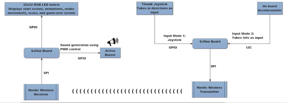
The design flow diagram of the project is shown below.
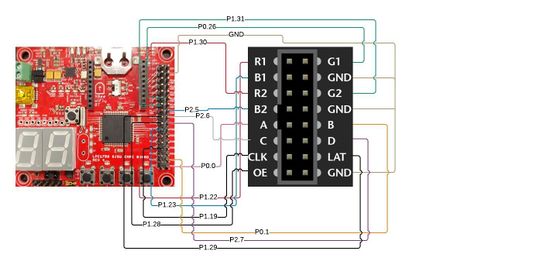
The Hardware design for baem geim involves the use of two SJone LPC1758 microcontroller boards, 32x32 RGB LED Matrix, Joystick module, Nordic Wireless Transceiver and Active Buzzer as described below. Pin configuration information for integration with PCB and power source have been detailed.
LED Matrix
The Project uses 32x32 6mm pitch RGB LED Matrix consisting of 1024 RGB LEDs.
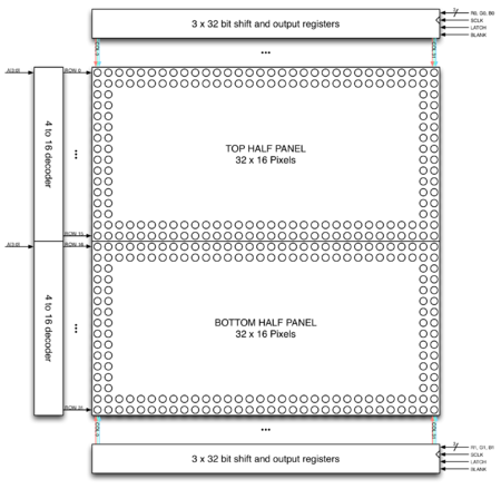
32 rows of LED matrix have been divided into 16 interleaved sections/strips. The first section is the 1st 'row' and 16th 'row' (32 x 2 RGB LEDs = 64 RGB LEDs) the second section is 2nd 'row' and 17th 'row' and so on.
On the PCB is 12 LED driver chips. These are like 74HC595s but they have 16 outputs and they are constant current. 16 outputs * 12 chips = 192 LEDs that can be controlled at once, and 64 * 3 (R G and B) = 192. So now the design comes together. We can have 192 outputs that can control one line at a time, with each of 192 R, G and B LEDs either on or off. The LPC1758 controller selects which section to currently draw (using A, B, C and D address pins - 4 bits can have 16 values). Once the address is set, the controller clocks out 192 bits of data (24 bytes) and latches it. Then it increments the address and clocks out another 192 bits, etc until it gets to address #15, then it sets the address back to #0.
To light up an individual pixel, appropriate row value is loaded on to the address pins A,B,C & D, Clock is set out to traverse the row
and when required pixel is reached, the latch is set high to turn ON the LED.
We have used the Adaafruit GFX libaray. In this library a 3D array of size 32*32*3= 3072 bytes is used. This 3D array basically represents the whole matrix with the three RGB values. Each function in the library takes the arguments of rows and columns and just makes the corresponding byte high in the matrix. The update display function is called in a repetitive interrupt function. This function loads travesses the 3D array and selects the appropriate row and loads the row using clk pin and finally latches in the value.
Tip: Try to get drawpixel function working first.
Technical Specification:
Dimensions: 190.5mm x 190.5mm x 14mm / 7.5" x 7.5" x 0.55"
Panel weight with IDC cables and power cable: 357.51g
5V regulated power input, 4A max (all LEDs on)
5V data logic level input
2000 mcd LEDs on 6mm pitch
1/16 scan rate
Indoor display, 150 degree visibility
Joystick
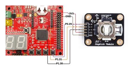
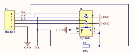
The project uses a 2-axis self centered joystick module from osepp. Its goal is to communicate motion in 2D to SJone board. This is achieved by using two independent 10K potentiometers (one per axis) which can be used as dual adjustable voltage dividers, providing 2-axis analog input in a control stick form. The Joystick stick design consists of Gimbal mechanism along with two potentiometers. When joystick is rotated, it moves a narrow rod, that sits in two rotatable shafts (Gimbal). One of the shafts allows motion in the X-axis(left-right) while the other allows motion in the Y-axis (up-down). Tilting it forward and backward pivots the Y-axis shaft, while tilting it left to right pivots X-axis shaft. Moving it diagonally pivots both shafts.
To read the joystick's physical position, we need to measure the change in resistance of potentiometer connected to each joystick shaft. The change can be read by LPC microcontroller's analog pin using ADC. With the microcontroller's 12-bit resolution, the values on each analog channel(axis) can vary from 0 to 4095. Thus, if the stick is moved on X-axis from one end to the other, the values change from 0 to 4095 and similar thing happens when it's moved along Y-axis. At Joystick's default position, its value is about 2048.
Technical Specification:
Operating voltage output : 3.3V – 5V MAX
Analog input
two 10K potentiometers with common ground per axis
Spring auto return to center on knob
Operating temp range: +32°F to +158°F (0°C to +70°C)
Unit Weight: 4 oz
Printed Circuit Board (PCB)
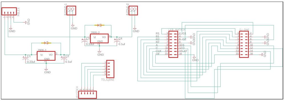
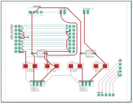
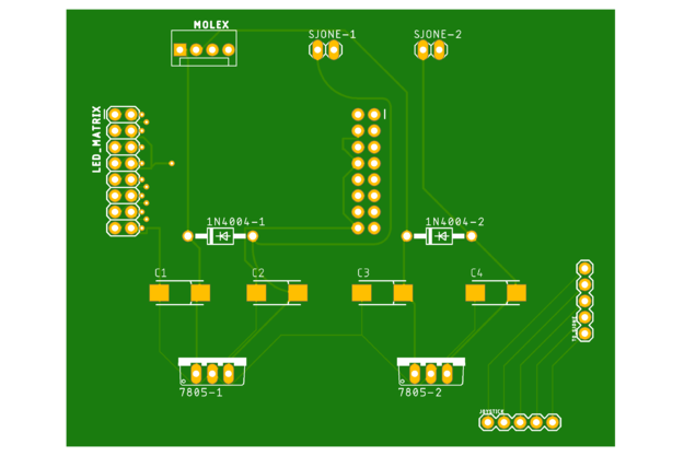
The PCB schematic and Layout have been designed using Eagle 9.2.2. The circuit board consists of single power supply which will be powering
- Transmitter SJone Board (5.0V)
- Receiver SJOne Board (5.0V)
The Circuit uses LM7805 Voltage regulator IC from Texas Instruments to meet the power requirements. The output of voltage regulator will be typically 5V, 1.5A thus preventing excess current to SJone boards. 9V, 4A adapter was used to power the LED Matrix. The LED Matrix which comes with dual Molex headers. Each of the two were safely connected to LED Matrix and Circuit board to power them accordingly. The circuit design has been made robust and versatile. The voltage regulator uses decoupling capacitors placed in parallel at input and output. They bypass the AC component at the input and improve the transient response at the output. Further, a diode has been connected in shunt across the regulator to provide reverse bias protection.
The circuit board also has provisions to LED Matrix, SJone board (Output Module) and Joystick module for integration.
Hardware Interface
Nordic Wireless
The project uses nRF24L01+ single chip 2.4GHZ transceiver rooted on SJone board to establish wireless communication between input and output modules. It uses embedded baseband protocol engine (Enhanced ShockBurst™), suitable for ultra low power wireless applications. The nRF24L01+ is designed for operation in the world wide ISM frequency band at 2.400 - 2.4835GHz. It is configured and operated through Serial Peripheral Interface (SPI0) of LPC1758 microcontroller. The embedded baseband protocol engine (Enhanced ShockBurst™) is based on packet communication and supports various modes from manual operation to advanced autonomous protocol operation. Internal FIFOs ensure a smooth data flow between the radio front end and the system’s MCU. Enhanced Shock-Burst™ reduces system cost by handling all the high speed link layer operations. The radio front end uses GFSK modulation. It consists of 126 different RF channels, which gives a possibility to have a network of 125 independently working modems in one place. It has a power consumption of about 12mA during transmission which is even lower than a single LED. Its operating voltage is between 1.8 and 3.7V.
Software Design and Implementation
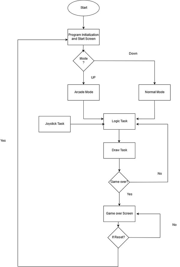
The general game flow of our project can be represented by the following flow chart.
Tasks
The game design consists of three independent tasks. First task polls on the user to enter the mode of the game (Normal/Arcade) and has been given the highest priority. The second task consists of draw pixel logic to generate the snake on the display console. The third task repeatedly polls for input from joystick which is used as reference for the snake motion.
Logic Task
Logic task calculates the length of snake body by using the snake's head as a reference. It also updates the row and column coordinates based on the joystick task input. The spawning of ordinary fruit, bonus fruit and evil fruit along with conditions when any of these fruits are eaten by the snake are also handled in this task. Finally, it checks for the game over condition.
Snake Body Generation
This section of code is used to compute the coordinates of the snake's body. The X-Y coordinates of the snake's head at any particular instant is considered as a reference to generate the snake body. The current instance of snake head is copied to a register and a loop is run to the length of the snake body. Finally, coordinate values at every index is pushed back by one.
The code snippet for the snake's body generation is given below:
    int prevX = tailX[0];          // tailX and tailY represents co-ordinates of the snake's body
    int prevY = tailY[0];
    tailX[0] = x;
    tailY[0] = y;
    int prev2X, prev2Y;
    for (int i = 1; i < nTail; i++) {
        prev2X = tailX[i];
        prev2Y = tailY[i];
        tailX[i] = prevX;
        tailY[i] = prevY;
        prevX = prev2X;
        prevY = prev2Y;
Snake Direction
The direction of input for snake is obtained from Joystick. Based on the input, new coordinates are computed to determine next state direction of snake. Boundary conditions have been taken into consideration for Normal and Arcade mode.
Pseudo Code:
 switch (dir)
    {
        case LEFT:
            y--;
            if(y<0)
            {
                y=width-1;
            }

            break;

        case RIGHT:
            y++;

            if(y>width-1)
            {
                y=0;
            }
            break;

        case UP:
            x--;
            if(x<0)
            {
                x=width-1;
            }
            break;

        case DOWN:
            x++;
            if(x>width-1)
            {
                x=0;
            }
            break;
        case STOP:
            indexX = x;
            indexY = y;
   }
Game Over Logic
In arcade mode, if the snake's head collides either with itself or wall border, the gameover function is called which will print the score. In normal mode, gameover condition is determined only when the snake comes in contact with its own body.
Pseudo code:
//Gameover condition for arcade mode
        if(snake's head touches the wall)
        {
            set 'gameover' flag to true;

            Gameover();                                    //this function displays scores
        }
        for (int i = 1; i < snake's body; i++) {
            if (snakes's head == snake's body)             // snake eating itself
            {
               set 'gameover' flag to true;

            Gameover();                                    //this function displays scores
            }

//Gameover condition for normal mode

        for (int i = 1; i < snake's body; i++) {
            if (snakes's head == snake's body)             // snake eating itself
            {
               set 'gameover' flag to true;

            Gameover();                                    //this function displays scores
            }
Draw Task
Two LED matrix coordinates in a loop scale through all possible rows and columns, at an instance when LED Matrix coordinates equalizes with coordinates of snake head , the corresponding LED pixel(s) is/are turned ON and other pixels are turned OFF.
Pseudo code:
       if (LED Matrix coordinates == snake head's coordinate)
       {
           glow_that_pixel;
       }
       else {
                bool print = false;
                for (int k = 0; k < nTail; k++) {
                    if (LED matrix's coordinates == snake body's coordinate)
                       {
                          glow_those_corresponding_pixels;
                          print = true;
                       }
                }
                if(!print)
                   all_other_pixels_turned_off;
       }
Joystick Task
This task receives the direction input for the joystick at delay interval of time. Nordic wireless API is used for wireless reception of the joystick's direction.A record of previous direction of the snake movement is taken into consideration to avoid overlapping of the snake when opposite direction is input.
Pseudo code:
    wireless_get_rx_pkt(&direction, delay);
    if(direction == UP)
    {
        if(precious_direction != DOWN)             //prevents conflict of opposite directions
        {
            direction = UP;
            precious_direction = UP;
        }
        pause_flag = false;
    }

    else if(direction == DOWN)
    {
        if(precious_direction != UP)             //prevents conflict of opposite directions
        {
            direction = DOWN;
            precious_direction = DOWN;
        }
        pause_flag = false;
    }

    else if(direction == LEFT)
    {
        if(precious_direction != RIGHT)             //prevents conflict of opposite directions
        {
            direction = LEFT;
            precious_direction = LEFT;
        }
        pause_flag = false;
    }

    else if(direction == RIGHT)
    {
        if(precious_direction != LEFT)             //prevents conflict of opposite directions
        {
            direction = RIGHT;
            precious_direction = RIGHT;
        }
        pause_flag = false;
    }

    }

    else if(direction == RESET)                          //Condition to reset the game
    {
        if(gameover_flag == false  &&  pause_flag==false)
        {
            direction = STOP;
            pause_flag = true;
            direction = previous_direction;
        }
        else if(gameover_flag == true)
        {
            clear_screen();
            StartScreen();
            Setup();

        }
    }
Thumb Joystick - SJOne Board interface
The thumb joystick communicates with LPC1758 controller via ADC pins. An ADC driver is designed which enables the joystick to be interfaced with the input module .Each of the 2 axes of the joystick makes use of channels 4 and 5 of the ADC respectively. Once the direction input is provided by the user, nordic wireless API wirelessly transmits the data to the output module.
Pseudo Code:
void initialize_ADC_driver()
{

   power up the ADC peripheral;
   make A/D converter operational;
   set clock frequency to 12Mhz;
   select channel 4 and 5;
   enable burst mode;
   set channel 4 for x-axis;
   set channel 5 for y-axis;

}

void joystick_actions()
{

  if(x_axis_value > 3500)
    {

       set 'directions' enum to right;
       wireless_send(direction); // Nordic wireless 'send' API
    }

  else if(x_axis_value < 200)
    {

       set ''directions' enum to left;
       wireless_send(direction);
    }

  else if(y_axis_value < 3500)
    {

       set ''directions' enum to up;
       wireless_send(direction);
    }

  else if(y_axis_value < 200)
    {

       set ''directions' enum to down;
       wireless_send(direction);
    }

  else
     {

        do nothing;
     }
}
Features:
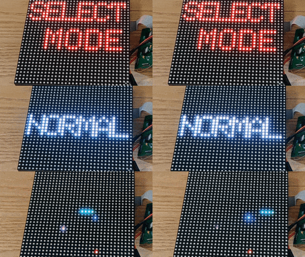
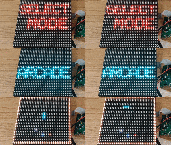
- Game Modes: Normal Mode (Wall absent) and Arcade Mode (Wall present).
- Game Pause: Game pauses if reset button is pressed during gameplay.
- Game Reset: Game resets if reset button is pressed after game over condition.
- Sound: Active buzzer used for generating sound during gameplay.
- Bonus Fruit: When eaten, score increases by 6 and snake's body increases by 2.
- Evil Fruit: When eaten, score decreases by 8 and snake's body increases by 2.
Testing & Technical Challenges
LED Matrix
- Non-availability of datasheet for ADAFRUIT 32x32 RGB LED Matrix was a major challenge. This made the understanding of pin configuration details difficult. Subsequently, we extracted ADAFRUIT GFX library and created an interface class to make it compatible with our project requirements.
- It was hard to determine the refresh rate for LED Matrix. Low refresh rate would cause display to flicker and a high refresh rate would slow down the display update rate thereby causing overhead. Through trial and error, we came up with a value of 500us for RIT interrupt which was an ideal refresh rate value.
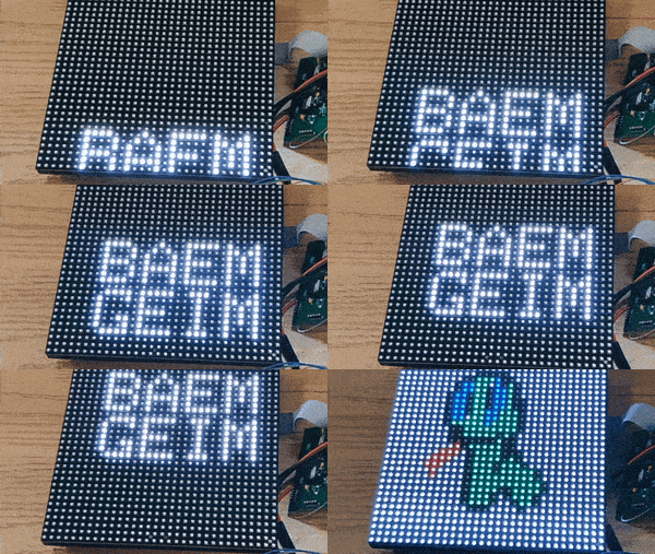
- In order to creatively enhance the game visual at start screen, we decided to display an image of a snake. We generated a bitmap using an 8-bit snake image. We manually determined the appropriate pixel position of the bitmap and provided the pixel colour. This was a tedious task as it had to done through trial and error.
Nordic Wireless Module and Joystick
- Initially, there was a 2-3 second delay to reflect change of direction of the snake received at the output module from the input joystick module. It was hard to determine the cause of delay. After diligent analysis, we found that the task delay at producer and consumer tasks were different which has caused the delay. This was fixed by using the same task delay to achieve synchronization between input and change in snake direction.
Game Algorithm
- It was hard to decide upon the approach to represent the snake's tail and display its real time motion on the screen. We finally came up with the logic of using an array where the first element of the array always indicated the snake's head and subsequent array elements indicated its body. Its real time movement was captured by pushing the elements of the array to the length of the snake's body.
- It was great challenge to implement the pause feature in the game. We had to capture the real time movement of the snake when the user hit pause and resume the game from same position. The push button switch on joystick was used to pause and game would resume with input direction. Initially, when direction opposite to that of current snake's movement was given, it used to reset the game. This was overcome by capturing instant before pause and then resuming from the same instant when direction was input.
- In order to display the player's score on game over, the integer value had to be converted to character and then displayed. Initially, while doing so, redundant values were also displayed along with the score. This was overcome by using ostringstream class which creates a buffer of type string and returns a string pointer. This was followed with the use of cstr function which outputs character to be printed on the console.
- Starting the game with initial snake body length was challenging due to the designed algorithm. This was overcome by calculating the snake body before start of the game by hard-coding the default direction on game start.
PCB
- Approach to design a PCB to meet the project requirements was complex. We had to redesign the circuit schematic and layout thrice to ensure that it was robust. Moreover, We had to import libraries from Sparkfun and adafruit for various components and also make sure that the same were available with Digikey.
<Bug/issue name>
- The LED Matrix display was intermittently flickering and we couldn't narrow down the reason behind it. Nothing was changed in the code, so we suspect the cause to be unstable circuit connections between output module and PCB.
- The top-leftmost LED blinks whenever the snake eats the fruit in the game. This was bug which couldn't be resolved.
- The PCB was designed presuming all 34 pins on SJone board could be interchangeably as GPIO for the LED Matrix. Post fabrication with some of the connections hard-grounded for LED Matrix, it couldn't be used interchangeably. As a result we had to manually connect the wires from PCB to LED Matrix.
Conclusion
The project was a success both in terms of output and learnings. We were able to design Snake game which has been controlled wirelessly using handheld joystick. It provided an exposure of developing drivers for 32x32 RGB LED Matrix, Nordic Wireless, Joystick, active buzzer and accelerometer. It helped us utilize the knowledge of FreeRTOS and GPIO driver gained through the CMPE-244 class.
Working as a team and having brainstorming sessions helped us in overcoming a lot bugs which we encountered during game design. Furthermore, it helped in expediting the integration, testing and debugging of the project days before final demonstration. On the whole, we had a wonderful experience of working in a team and developing a complete product using professional tools and techniques.
Project Video
Project Source Code
References
Acknowledgement
We would like to sincerely thank Professor Preetpal Kang for his allround guidance, feedback and support. His classroom lectures were significant in imparting knowledge on embedded systems. Further, we would like to thank ISA team for their advice.
References Used
[1] Adafruit 32x32 RGB Matrix
[2] 2-Axis Joystick Tutorial
[3] Nordic Wireless Datasheet
[4] Low Powered Mesh Network Stack

