Difference between revisions of "F13: POV Display"
Proj user5 (talk | contribs) (→Abstract) |
Proj user5 (talk | contribs) (→References) |
||
| (56 intermediate revisions by 2 users not shown) | |||
| Line 1: | Line 1: | ||
| − | + | == Web-Enabled Persistence of Vision Display == | |
| − | |||
| − | |||
| − | |||
| − | |||
| − | |||
| − | |||
| − | |||
| − | |||
| − | |||
| − | |||
| − | |||
| − | == Web-Enabled | ||
== Abstract == | == Abstract == | ||
| − | The Persistence of Vision (POV) device will display a message that is input by a remote user via a website setup for this project. The message will be received by the microcontroller using a Wifly RN-XV module integrated onto the | + | The purpose of the project is to build a Persistence of Vision (POV) device that is controlled by the SJSU One board. The POV device will display a message that is input by a remote user via a website setup for this project. The message will be received by the microcontroller using a Wifly RN-XV module integrated onto the SJSU board. The microcontroller will interpret the message and drive the LEDs via an SPI interface to display the message on the POV device. |
Figure 1 shows the overall system diagram: | Figure 1 shows the overall system diagram: | ||
| − | [[CMPE240 F13 POV1.JPG]] | + | [[File:CMPE240 F13 POV1.JPG|center|frame]] |
| + | <br> | ||
== Objectives & Introduction == | == Objectives & Introduction == | ||
| − | + | The objective of this project is to learn how to use the SJSU One board and to control external devices using the interfaces provided on the board. Two types of interfaces will be used. The microcontroller will communicate with the Wifly RN-XV module via a UART interface. Then the LEDs will be controlled using an SPI interface. The LEDs will be mounted onto the mechanical POV device and the microcontroller will drive the LEDs to produce the message. A website will be setup to provide a user interface to control the device.<br> | |
| + | |||
| + | The team will be divided into two groups. Team 1 will be responsible for the web interface and integration of the Wifly module on the SJSU board to communicate with the website. Team 2 will build the POV device and write the driver to display the user message on the POV display. A summary of the team and responsibilities is shown below:<br> | ||
| + | <br> | ||
=== Team Members & Responsibilities === | === Team Members & Responsibilities === | ||
| Line 27: | Line 19: | ||
- Website Development<br> | - Website Development<br> | ||
- Wifly module setup<br> | - Wifly module setup<br> | ||
| − | - Front end communication from website to | + | - Front end communication from website to microcontroller via the Wifly RN-XV module<br> |
Team 2 (Jasko Begovic and Thu Hoang)<br> | Team 2 (Jasko Begovic and Thu Hoang)<br> | ||
| − | - Mechanical POV device<br> | + | - Construction of the Mechanical POV device<br> |
| − | - LED | + | - LED driver software<br> |
| + | <br> | ||
| + | Both teams will participate in the integration and testing of the project. | ||
| + | The project will take 6 weeks to complete. The following table shows weekly project milestones and the team's progress.<br> | ||
| + | <br> | ||
{| {{table}} | {| {{table}} | ||
| align="center" style="background:#f0f0f0;"|'''Date Planned''' | | align="center" style="background:#f0f0f0;"|'''Date Planned''' | ||
| Line 42: | Line 38: | ||
| 29-Oct||Integrate Wifly to SJSU board and connect to Wifi connection||Complete | | 29-Oct||Integrate Wifly to SJSU board and connect to Wifi connection||Complete | ||
|- | |- | ||
| − | | 5-Nov||Finish mechanical assembly & any electrical interfaces (Hall effect switch.) Read datasheets, obtain necessary libraries for LED device, understand & modify libraries to work with SJSU board Setup Website for user interface to the device|| | + | | 5-Nov||Finish mechanical assembly & any electrical interfaces (Hall effect switch.) Read datasheets, obtain necessary libraries for LED device, understand & modify libraries to work with SJSU board Setup Website for user interface to the device||Complete |
|- | |- | ||
| − | | 12-Nov||Implement code to receive data from website via the Wifly module|| | + | | 12-Nov||Implement code to receive data from website via the Wifly module||Complete |
|- | |- | ||
| − | | 19-Nov||Finish code for LED driver. | + | | 19-Nov||Finish code for LED driver. Display the alphabet. Start integration of the Wifly portion with the POV device ||Complete |
|- | |- | ||
| − | | 26-Nov|| Project testing. Have working Assembled code with Web-half & test by inputing various strings via the website|| | + | | 26-Nov|| Project testing. Have working Assembled code with Web-half & test by inputing various strings via the website||Complete |
|- | |- | ||
| − | | 3-Dec||Present demonstration and submission of project report|| | + | | 3-Dec||Present demonstration and submission of project report||Complete |
| + | |- | ||
| + | | 7-Dec||Present demonstration and submission of project report||Complete | ||
|} | |} | ||
| Line 57: | Line 55: | ||
| align="center" style="background:#f0f0f0;"|'''Part''' | | align="center" style="background:#f0f0f0;"|'''Part''' | ||
| align="center" style="background:#f0f0f0;"|'''Cost''' | | align="center" style="background:#f0f0f0;"|'''Cost''' | ||
| + | |- | ||
| + | | SJSU One board||$75 | ||
|- | |- | ||
| Wifly RX-NV module||$35 | | Wifly RX-NV module||$35 | ||
|- | |- | ||
| + | | Web Hosting through iPage||$12 | ||
| + | |- | ||
| + | | LPD8806 strips (2) Adafruit.com product ID: 306||$30 | ||
| + | |- | ||
| + | | Motor (MT-WSM600 Batteryspace.com) - device 1||$12 | ||
| + | |- | ||
| + | | Motor controller (LT317K) - device 1||$0 | ||
| + | |- | ||
| + | | 5V regulator (LT317T) - device 1||$0 | ||
| + | |- | ||
| + | | Pine strips - device 1||$12 | ||
| + | |- | ||
| + | | 9V battery pack - device 1||$4 | ||
| + | |- | ||
| + | | Hall Effect Sensor - device 1||$2 | ||
| + | |- | ||
| + | | Blender - device 2||$0 | ||
| + | |- | ||
| + | | Large Can - device 2||$0 | ||
| + | |- | ||
| + | | 4-AA battery pack - device 2||$0 | ||
| + | |- | ||
| + | |} | ||
| + | == Design & Implementation == | ||
| + | The user interface for the project will be http://povdisplay.com. The user will input a message to be displayed on the POV device, as well as, the RGB color to use. This section will detail the hardware and software components of the POV device. | ||
| + | |||
| + | === Hardware Design === | ||
| + | The hardware design section will discuss the details of the POV device. The SJSU board will be installed onto the device. The following section outlines the mechanical design | ||
| + | <br> | ||
| + | '''Mechanical Requirements'''<br> | ||
| + | The POV display requirements were necessarily derived from the physical dimensions of the LED strip and the dot matrix font that was chosen. The strips chosen are Adafruit LPD8806 RGB strips, primarily because of their high refresh rate at 4000 Hz[4]. The font chosen is reproduced below in Figure 1 for discussion.<br> | ||
| + | |||
| + | |||
| + | [[File:CMPE240_F13_POV2_Alphabet.jpg|center|frame]]<br> | ||
| + | Figure 2: Dot Matrix Font for the POV display <br> | ||
| + | |||
| + | In order to display a single character, the display’s width should be a minimum of 5 pixels wide. Using the LED strip’s dimensions as a starting point, the RGB pixels are 5050, meaning half a centimeter wide by half a centimeter tall, and are spaced 31 mm apart. If the strip’s pixel spacing is maintained, then the display should be 6” wide as a minimum so that the viewer can see 5 pixels across. If instead two strips of LEDs are used, with the strips staggered vertically so that the LED spacing is halved, then only a 3” minimum diameter is needed. | ||
| + | |||
| + | |||
| + | [[File:CMPE240_F13_POV3_LEDstrip.jpg|center|frame]] | ||
| + | Figure 3: Diagram of staggered LED strips <br> | ||
| + | |||
| + | Initially, a personal blower was thought to be sufficient to provide the framework on which to build the POV display. The rotating cylinder of blower has dimensions of 3” diameter x 5” tall. This is sufficiently wide to display a single character; however, with the manageable sized cylinder came the small sized motor. Since this motor was not intended to move anything but air, it does not have enough torque to move the combined weight of the board, LED strips, wires, and battery pack. A motor with a higher torque is needed. | ||
| + | |||
| + | In addition to the higher torque, the motor needs to have sufficient speed. POV displays work on the principle that an afterimage persists on the retina of the human eye for approximately 40 ms[2] (1/25th of a second). Therefore the motor must be able to spin a pixel a complete revolution in 40 ms or 25 Hz. 25 cycles per second translates to 1500 rpm minimum. | ||
| + | |||
| + | Suppose now that the display is 12.6” or 32 cm in diameter. If no horizontal spacing between the pixels are allowed, then that translates to pi*32 /0.5 = 201 pixels around the circumference. The entire circumference must be refreshed in 40 ms to maintain persistence of vision. When using a single strip, the LED must transition from one column to the next in 40ms/201 ~ 0.2 ms. Therefore the minimum refresh rate needed for a display of this size is 1 / 0.2 ms = 5 kHz, slightly higher than the refresh rate possible with the LPD8806. Therefore, some horizontal spacing between the pixels is required for a display of this size. If a spacing of 1 pixel is used, then the refresh rate can be halved to 2.5 kHz. | ||
| + | |||
| + | A display rotating at 1500 rpm that requires a high torque, high speed motor must be precisely machined to operate safely. Since this is not possible within the self-imposed budget constraints of the project, we chose the best possible speed that can operate safely with manually crated components. This motor is the 12V, 500 rpm motor from BatterySpace.com. For “Saturday morning cartoon” quality POV, 500 rpm is sufficient since the same picture is used 2 to 4 times when running at 25 Hz[2], thus reducing the speed requirements by half to a quarter, and the 1500 rpm can be reduced to 750 down to 375 rpm. | ||
| + | |||
| + | The LED strips naturally lend themselves to the SPI bus since it is wired for serial communications with a Data In and Clk In and a Data Out and Clk Out. To refresh the 32 LEDs at 4 kHz with each LED requiring 24 bits of information would require the SPI bus to operate at 32 x 24 x 4 k = 3.072 MHz at the very least. Fortunately, testing shows that the SPI bus can be operated at this speed and up to 6 MHz without issues. From the datasheet, each 5050 LED requires approximately 5V and 60 mA[5] to operate, thus the POV display of 32 LEDs would require approximately 2A peak. This kind of current requires either a four-pack of AA battery or a 9V battery regulated down to 5V. | ||
| + | |||
| + | The requirements are summarized below: | ||
| + | |||
| + | {| {{table}} | ||
| + | | align="center" style="background:#f0f0f0;"|'''Requirement''' | ||
| + | | align="center" style="background:#f0f0f0;"|'''Detail''' | ||
| + | |- | ||
| + | |Font to Display||Figure 1 | ||
| + | |- | ||
| + | |Motor RPM||at least 375 rpm | ||
| + | |- | ||
| + | |Motor torque||Dependent on mass of rotor, thus rotor needs to be as light as possible | ||
| + | |- | ||
| + | |Bits per LED||24 | ||
| + | |- | ||
| + | |LEDs per display||32 | ||
| + | |- | ||
| + | |SPI bus speed||at least 3.072 MHz | ||
| + | |- | ||
| + | |Power||4 x 1.5V AA batteries or 9V regulated to 5V | ||
| + | |} | ||
| + | <br> | ||
| + | Figure 4 depicts the POV display that was initially crafted for this project to meet the requirements listed above.<br> | ||
| + | |||
| + | [[File:CMPE240_F13_POV4_MechanicalDiagram.jpg|center|frame]] | ||
| + | Figure 4: Mechanical Diagram of POV display <br> | ||
| + | |||
| + | During testing and development, however, the internal gear of the motor above was worn out and thus a second POV display was crafted with the help of a blender. | ||
| + | |||
| + | This POV display is physically smaller so closer spacing of the LEDs is required. To this end, the LED strips were sliced and arranged in rows with 2 LEDs per row as shown in the figure below. This was necessary because each LPD8806 chip drives two LEDs and thus 2 LEDs is the smallest unit that the strip can be divided into. Only one column is used as the active column, however. In order to reduce weight and complexity, the number of LEDs was reduced from 32 down to 14, with 7 active LEDs. One aspect of this design is that achieving torque and rpm would not be an issue as the blender motor is more than capable of driving the mass at 1500 rpm. The requirements for this POV display are summarized below: | ||
| + | |||
| + | {| {{table}} | ||
| + | | align="center" style="background:#f0f0f0;"|'''Requirement''' | ||
| + | | align="center" style="background:#f0f0f0;"|'''Detail''' | ||
| + | |- | ||
| + | |Font to Display||Figure 1 | ||
| + | |- | ||
| + | |Motor RPM||1500 rpm minimum | ||
| + | |- | ||
| + | |Motor torque||More than sufficient to be of concern | ||
| + | |- | ||
| + | |Bits per LED||24 | ||
| + | |- | ||
| + | |LEDs per display||7 active, 7 non-active | ||
| + | |- | ||
| + | |SPI bus speed||at least 1.344 MHz | ||
| + | |- | ||
| + | |Power||4 x 1.5V AA batteries or 9V regulated to 5V | ||
|} | |} | ||
| + | <br> | ||
| + | Figure 5 depicts the POV display crafted. | ||
| + | |||
| + | [[File:CMPE240_F13_POV22_MechanicalDiagram2.jpg|center|frame]] | ||
| + | |||
| + | <br> | ||
| + | Pseudo Code for LED Drive Portion | ||
| + | The main issue with the LPD8806 stem from the fact that its datasheet is available only in Chinese and the English translation is sorely lacking, especially in the details of communication with the device. The communication sequence was reverse engineered by previous users and is available at [3]. The task remaining is to adapt the library for the SJSU board and to write the code for the POV display according to its physical build. Since the first POV display’s motor was burned out, this pseudo-code concentrates on that of the second display, though the two codes are similar. | ||
| − | + | Initialize SPI bus | |
| − | + | Initialize LPD8806 Strip | |
| + | Initialize Font Map | ||
| + | [Obtain string & num_char from WiFly Portion] | ||
| − | + | For (int j=0; j<=num_char; j++) { | |
| + | RenderChar(string[j], color); | ||
| + | Turn off pixels | ||
| + | Set spacing between characters with delay_us | ||
| + | } | ||
| − | + | RenderChar(char, color) { | |
| − | + | Switch (char) { | |
| + | Case ‘A’: writechar(index, color); // index into Font Map for the character ‘A’ | ||
| + | … | ||
| + | Case ‘Z’: writechar(index, color); // index into Font Map for the character ‘Z’ | ||
| + | Default: writechar(index, color); // index into Font Map for the space character | ||
| + | } | ||
| − | === | + | Writechar(char,color) { |
| − | + | For (col_index=0; col_index <col_index+5; col_index++) { // Font chosen 5 rows x 8 cols, though only 7 | |
| + | For (row_index=0; row_index< 8; row_index++) { // is needed to display upper case letters | ||
| + | Select pixel position according to PHYSICAL position on the strip | ||
| + | If (Font map bit is 1) { | ||
| + | Set_pixel(pixel position, color); | ||
| + | Else | ||
| + | Set_pixel(pixel position, color=0=OFF); | ||
| + | } | ||
| + | } | ||
| + | Set spacing within character with delay_us | ||
| + | } | ||
| + | } | ||
| − | + | The font map is an 8-bit 1-dimensional integer array initialized according to the rotational direction of the rotor. In this case the rotor is rotating such that the vertical LED strip scans from left to right. To simplify matters for the first cut, the letters are of fixed width. | |
| − | In this | ||
=== Software Design === | === Software Design === | ||
| − | + | The software will need to control the wifly RN-XV module via a UART interface to receive the website data and also drive the LED strip using an SPI interface. The following section outlines the design of the software<br> | |
=== Implementation === | === Implementation === | ||
This section includes implementation, but again, not the details, just the high level. For example, you can list the steps it takes to communicate over a sensor, or the steps needed to write a page of memory onto SPI Flash. You can include sub-sections for each of your component implementation. | This section includes implementation, but again, not the details, just the high level. For example, you can list the steps it takes to communicate over a sensor, or the steps needed to write a page of memory onto SPI Flash. You can include sub-sections for each of your component implementation. | ||
| − | == | + | After turn on or reset the system initializes the Wifly by following these steps: |
| − | + | ||
| − | + | *set DHCP ON (get IP address and gateway from AP) | |
| + | *set router SSID | ||
| + | *set router authentication mode (if necessary) | ||
| + | *set router password (if necessary) | ||
| + | *set router channel (or set to scan) | ||
| + | *set router channel scan mask (if router channel is set to scan) | ||
| + | *set router policy for automatically joining/associating with network access points | ||
| + | *set comm parameters (match, time and size) | ||
| + | *set ip protocol to HTTP client mode | ||
| + | *set dns name for the website the system will connect to | ||
| + | *set remote host port number | ||
| + | *save all parameters | ||
| + | *reboot | ||
| + | |||
| + | The system then logs into the website to check the message and color set by the user. The message is then compared to the message actively being displayed (if any) and if it is different it will update the message being displayed. The system then will start displaying the message by communicating to the LED strip using the SPI protocol. The controller will set the values for each individual LED (wether they are on or off and the color), Each letter of the message will be displayed. After the message has been displayed completely 200 times the system will connect to the webpage to verify if there is a new message and the loop will repeat. See Figure below for the flow diagram. | ||
| + | |||
| + | [[File:CMPE240_F16_POV8_POVdevice2.jpg|center|frame]] | ||
| + | <br> | ||
| + | === Website === | ||
| + | <br> | ||
| + | A website has been designed to receive the user input. The website is hosted by iPage and the domain is www.povdisplay.com. The website will allow the end user to submit a message and RGB color values to display on the device. The website will use php code and a MySQL database to store the user input. The wifly module will poll the website to receive the data. | ||
| + | |||
| + | A screenshoot of the website is shown below. | ||
| + | |||
| + | [[File:CMPE240_F13_POV20_website.jpg|center|frame]] | ||
| + | |||
| + | The php file called by the wifly module is called printinput.php. A screenshot showing the example data is shown below. | ||
| − | + | [[File:CMPE240_F13_POV21_php.jpg|center|frame]] | |
| − | == | + | == Testing & Technical Challenges == |
| − | + | <br> | |
| + | *Building the Mechanical device was a challenge. The device needed to be precisely balanced in order to spin in a stable manner | ||
| + | *Wifi connection issues. The documentation for the Wifly RN-XV module was difficult to follow. Also some group members had routers that did not accept the connection. | ||
| + | *Synchronization of the LEDs with the motor speed. The motor did not spin at a constant rate. A sensor is needed to allow the software to compensate for the inconsistencies in the motor. | ||
| + | <br> | ||
| + | === Future Improvements === | ||
| + | <br> | ||
| + | *Stabilize display refresh using Hall Effect Sensor | ||
| + | *Expand the radius of the device to display a longer message. Also can consider expanding to more LEDs (currently 14) | ||
| + | *Addition of various text effects | ||
| + | *Add the capability to display a bitmap image | ||
| + | <br> | ||
== Conclusion == | == Conclusion == | ||
| − | + | This was a fun project to complete. It was rewarding to produce a device that could be controlled by anyone with an internet connection. The team worked well together and learned a lot about the SJSU board and how to use it. In addition, the team got experience building a webpage, writing php code, using the WIfly module, wiring and driving the LEDs. and writing C++ drivers. Probably the biggest challenge of all was building the mechanical device itself. | |
=== Project Video === | === Project Video === | ||
| − | + | [[https://www.youtube.com/watch?v=_M4PMe9kuWI Project Video]] | |
| + | <br> | ||
| + | === Project Photos === | ||
| + | [[File:CMPE240_F13_POV8_POVdevice2.jpg|center|frame]]<br> | ||
| + | [[File:CMPE240_F13_POV9_SJSUboard.jpg|center|frame]]<br> | ||
| + | [[File:CMPE240_F13_POV10_battery.jpg|center|frame]]<br> | ||
| + | [[File:CMPE240_F13_POV7_GroupNames.jpg|center|frame]]<br> | ||
=== Project Source Code === | === Project Source Code === | ||
| − | + | * [https://sourceforge.net/projects/sjsu/files/CmpE240_LM_F2013/ Sourceforge link for source code] | |
== References == | == References == | ||
| − | + | [1] http://www.identifont.com/similar?1SS<br> | |
| − | + | [2] http://en.wikipedia.org/wiki/Persistence_of_vision<br> | |
| − | + | [3] https://github.com/cjbaar/LPD8806<br> | |
| − | = | + | [4] https://solarbotics.com/download.php?file=1889<br> |
| − | + | [5] http://www.wayjun.com/Datasheet/Led/5050%20SMD%20LED.pdf<br> | |
| − | + | [6] Preet's Sprinkler System Code<br> | |
| − | + | [7] [http://dlnmh9ip6v2uc.cloudfront.net/datasheets/Wireless/WiFi/WiFly-RN-UM.pdf Wifly User Manual] | |
| − | |||
Latest revision as of 02:04, 8 December 2013
Contents
Web-Enabled Persistence of Vision Display
Abstract
The purpose of the project is to build a Persistence of Vision (POV) device that is controlled by the SJSU One board. The POV device will display a message that is input by a remote user via a website setup for this project. The message will be received by the microcontroller using a Wifly RN-XV module integrated onto the SJSU board. The microcontroller will interpret the message and drive the LEDs via an SPI interface to display the message on the POV device.
Figure 1 shows the overall system diagram:
Objectives & Introduction
The objective of this project is to learn how to use the SJSU One board and to control external devices using the interfaces provided on the board. Two types of interfaces will be used. The microcontroller will communicate with the Wifly RN-XV module via a UART interface. Then the LEDs will be controlled using an SPI interface. The LEDs will be mounted onto the mechanical POV device and the microcontroller will drive the LEDs to produce the message. A website will be setup to provide a user interface to control the device.
The team will be divided into two groups. Team 1 will be responsible for the web interface and integration of the Wifly module on the SJSU board to communicate with the website. Team 2 will build the POV device and write the driver to display the user message on the POV display. A summary of the team and responsibilities is shown below:
Team Members & Responsibilities
Team 1 (Jorge Del Valle and Matt Heffner)
- Website Development
- Wifly module setup
- Front end communication from website to microcontroller via the Wifly RN-XV module
Team 2 (Jasko Begovic and Thu Hoang)
- Construction of the Mechanical POV device
- LED driver software
Both teams will participate in the integration and testing of the project.
The project will take 6 weeks to complete. The following table shows weekly project milestones and the team's progress.
| Date Planned | Milestone | Status |
| 22-Oct | Wifly part received; POV parts ordered and shipped | Complete |
| 29-Oct | Integrate Wifly to SJSU board and connect to Wifi connection | Complete |
| 5-Nov | Finish mechanical assembly & any electrical interfaces (Hall effect switch.) Read datasheets, obtain necessary libraries for LED device, understand & modify libraries to work with SJSU board Setup Website for user interface to the device | Complete |
| 12-Nov | Implement code to receive data from website via the Wifly module | Complete |
| 19-Nov | Finish code for LED driver. Display the alphabet. Start integration of the Wifly portion with the POV device | Complete |
| 26-Nov | Project testing. Have working Assembled code with Web-half & test by inputing various strings via the website | Complete |
| 3-Dec | Present demonstration and submission of project report | Complete |
| 7-Dec | Present demonstration and submission of project report | Complete |
Parts List & Cost
| Part | Cost |
| SJSU One board | $75 |
| Wifly RX-NV module | $35 |
| Web Hosting through iPage | $12 |
| LPD8806 strips (2) Adafruit.com product ID: 306 | $30 |
| Motor (MT-WSM600 Batteryspace.com) - device 1 | $12 |
| Motor controller (LT317K) - device 1 | $0 |
| 5V regulator (LT317T) - device 1 | $0 |
| Pine strips - device 1 | $12 |
| 9V battery pack - device 1 | $4 |
| Hall Effect Sensor - device 1 | $2 |
| Blender - device 2 | $0 |
| Large Can - device 2 | $0 |
| 4-AA battery pack - device 2 | $0 |
Design & Implementation
The user interface for the project will be http://povdisplay.com. The user will input a message to be displayed on the POV device, as well as, the RGB color to use. This section will detail the hardware and software components of the POV device.
Hardware Design
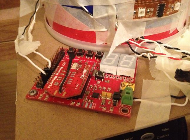
The hardware design section will discuss the details of the POV device. The SJSU board will be installed onto the device. The following section outlines the mechanical design
Mechanical Requirements
The POV display requirements were necessarily derived from the physical dimensions of the LED strip and the dot matrix font that was chosen. The strips chosen are Adafruit LPD8806 RGB strips, primarily because of their high refresh rate at 4000 Hz[4]. The font chosen is reproduced below in Figure 1 for discussion.
Figure 2: Dot Matrix Font for the POV display
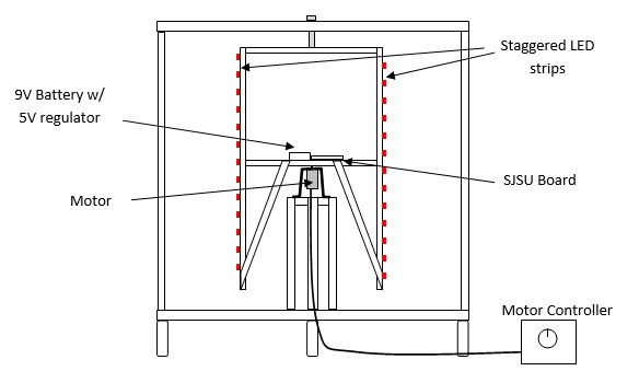
In order to display a single character, the display’s width should be a minimum of 5 pixels wide. Using the LED strip’s dimensions as a starting point, the RGB pixels are 5050, meaning half a centimeter wide by half a centimeter tall, and are spaced 31 mm apart. If the strip’s pixel spacing is maintained, then the display should be 6” wide as a minimum so that the viewer can see 5 pixels across. If instead two strips of LEDs are used, with the strips staggered vertically so that the LED spacing is halved, then only a 3” minimum diameter is needed.
Figure 3: Diagram of staggered LED strips
Initially, a personal blower was thought to be sufficient to provide the framework on which to build the POV display. The rotating cylinder of blower has dimensions of 3” diameter x 5” tall. This is sufficiently wide to display a single character; however, with the manageable sized cylinder came the small sized motor. Since this motor was not intended to move anything but air, it does not have enough torque to move the combined weight of the board, LED strips, wires, and battery pack. A motor with a higher torque is needed.
In addition to the higher torque, the motor needs to have sufficient speed. POV displays work on the principle that an afterimage persists on the retina of the human eye for approximately 40 ms[2] (1/25th of a second). Therefore the motor must be able to spin a pixel a complete revolution in 40 ms or 25 Hz. 25 cycles per second translates to 1500 rpm minimum.
Suppose now that the display is 12.6” or 32 cm in diameter. If no horizontal spacing between the pixels are allowed, then that translates to pi*32 /0.5 = 201 pixels around the circumference. The entire circumference must be refreshed in 40 ms to maintain persistence of vision. When using a single strip, the LED must transition from one column to the next in 40ms/201 ~ 0.2 ms. Therefore the minimum refresh rate needed for a display of this size is 1 / 0.2 ms = 5 kHz, slightly higher than the refresh rate possible with the LPD8806. Therefore, some horizontal spacing between the pixels is required for a display of this size. If a spacing of 1 pixel is used, then the refresh rate can be halved to 2.5 kHz.
A display rotating at 1500 rpm that requires a high torque, high speed motor must be precisely machined to operate safely. Since this is not possible within the self-imposed budget constraints of the project, we chose the best possible speed that can operate safely with manually crated components. This motor is the 12V, 500 rpm motor from BatterySpace.com. For “Saturday morning cartoon” quality POV, 500 rpm is sufficient since the same picture is used 2 to 4 times when running at 25 Hz[2], thus reducing the speed requirements by half to a quarter, and the 1500 rpm can be reduced to 750 down to 375 rpm.
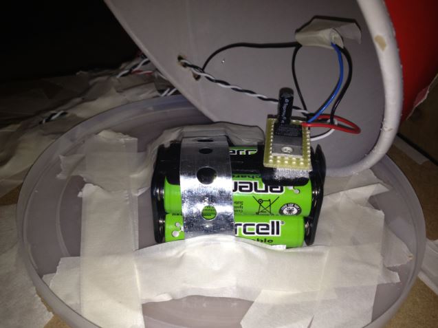
The LED strips naturally lend themselves to the SPI bus since it is wired for serial communications with a Data In and Clk In and a Data Out and Clk Out. To refresh the 32 LEDs at 4 kHz with each LED requiring 24 bits of information would require the SPI bus to operate at 32 x 24 x 4 k = 3.072 MHz at the very least. Fortunately, testing shows that the SPI bus can be operated at this speed and up to 6 MHz without issues. From the datasheet, each 5050 LED requires approximately 5V and 60 mA[5] to operate, thus the POV display of 32 LEDs would require approximately 2A peak. This kind of current requires either a four-pack of AA battery or a 9V battery regulated down to 5V.
The requirements are summarized below:
| Requirement | Detail |
| Font to Display | Figure 1 |
| Motor RPM | at least 375 rpm |
| Motor torque | Dependent on mass of rotor, thus rotor needs to be as light as possible |
| Bits per LED | 24 |
| LEDs per display | 32 |
| SPI bus speed | at least 3.072 MHz |
| Power | 4 x 1.5V AA batteries or 9V regulated to 5V |
Figure 4 depicts the POV display that was initially crafted for this project to meet the requirements listed above.
Figure 4: Mechanical Diagram of POV display
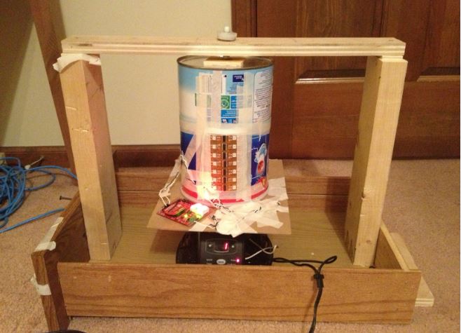
During testing and development, however, the internal gear of the motor above was worn out and thus a second POV display was crafted with the help of a blender.
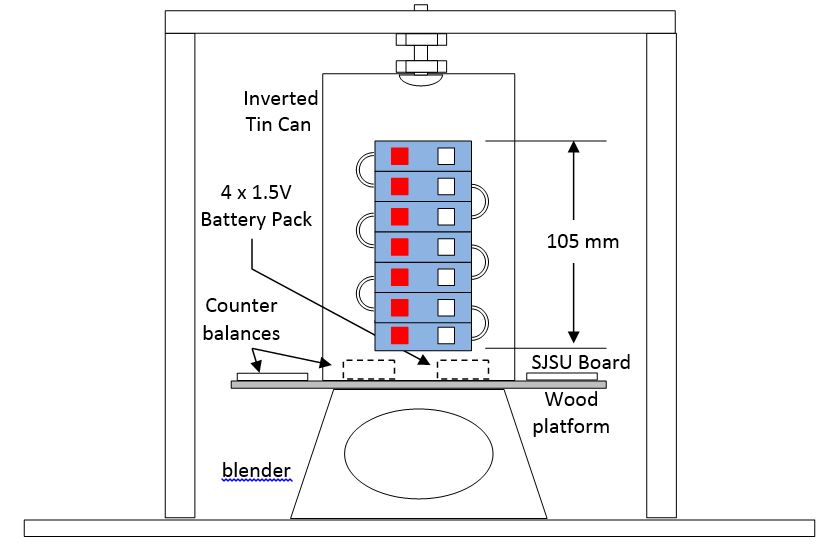
This POV display is physically smaller so closer spacing of the LEDs is required. To this end, the LED strips were sliced and arranged in rows with 2 LEDs per row as shown in the figure below. This was necessary because each LPD8806 chip drives two LEDs and thus 2 LEDs is the smallest unit that the strip can be divided into. Only one column is used as the active column, however. In order to reduce weight and complexity, the number of LEDs was reduced from 32 down to 14, with 7 active LEDs. One aspect of this design is that achieving torque and rpm would not be an issue as the blender motor is more than capable of driving the mass at 1500 rpm. The requirements for this POV display are summarized below:
| Requirement | Detail |
| Font to Display | Figure 1 |
| Motor RPM | 1500 rpm minimum |
| Motor torque | More than sufficient to be of concern |
| Bits per LED | 24 |
| LEDs per display | 7 active, 7 non-active |
| SPI bus speed | at least 1.344 MHz |
| Power | 4 x 1.5V AA batteries or 9V regulated to 5V |
Figure 5 depicts the POV display crafted.
Pseudo Code for LED Drive Portion
The main issue with the LPD8806 stem from the fact that its datasheet is available only in Chinese and the English translation is sorely lacking, especially in the details of communication with the device. The communication sequence was reverse engineered by previous users and is available at [3]. The task remaining is to adapt the library for the SJSU board and to write the code for the POV display according to its physical build. Since the first POV display’s motor was burned out, this pseudo-code concentrates on that of the second display, though the two codes are similar.
Initialize SPI bus Initialize LPD8806 Strip Initialize Font Map [Obtain string & num_char from WiFly Portion]
For (int j=0; j<=num_char; j++) {
 RenderChar(string[j], color);
 Turn off pixels
 Set spacing between characters with delay_us
}
RenderChar(char, color) {
 Switch (char) {
   Case ‘A’: writechar(index, color);     // index into Font Map for the character ‘A’
   …
   Case ‘Z’:  writechar(index, color);     // index into Font Map for the character ‘Z’
   Default: writechar(index, color);     // index into Font Map for the space character
}
Writechar(char,color) {
 For (col_index=0; col_index <col_index+5; col_index++) {     // Font chosen 5 rows x 8 cols, though only 7
   For (row_index=0; row_index< 8; row_index++) {	     // is needed to display upper case letters
     Select pixel position according to PHYSICAL position on the strip
     If (Font map bit is 1) {
       Set_pixel(pixel position, color);
     Else
       Set_pixel(pixel position, color=0=OFF);
     }
   }
   Set spacing within character with delay_us
 }
}
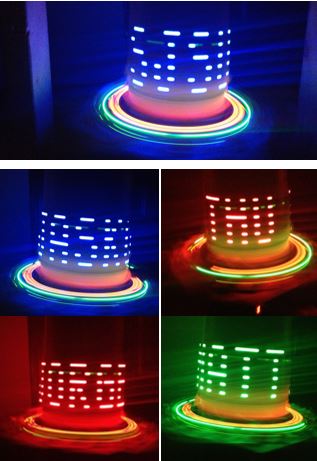
The font map is an 8-bit 1-dimensional integer array initialized according to the rotational direction of the rotor. In this case the rotor is rotating such that the vertical LED strip scans from left to right. To simplify matters for the first cut, the letters are of fixed width.
Software Design
The software will need to control the wifly RN-XV module via a UART interface to receive the website data and also drive the LED strip using an SPI interface. The following section outlines the design of the software
Implementation
This section includes implementation, but again, not the details, just the high level. For example, you can list the steps it takes to communicate over a sensor, or the steps needed to write a page of memory onto SPI Flash. You can include sub-sections for each of your component implementation.
After turn on or reset the system initializes the Wifly by following these steps:
- set DHCP ON (get IP address and gateway from AP)
- set router SSID
- set router authentication mode (if necessary)
- set router password (if necessary)
- set router channel (or set to scan)
- set router channel scan mask (if router channel is set to scan)
- set router policy for automatically joining/associating with network access points
- set comm parameters (match, time and size)
- set ip protocol to HTTP client mode
- set dns name for the website the system will connect to
- set remote host port number
- save all parameters
- reboot
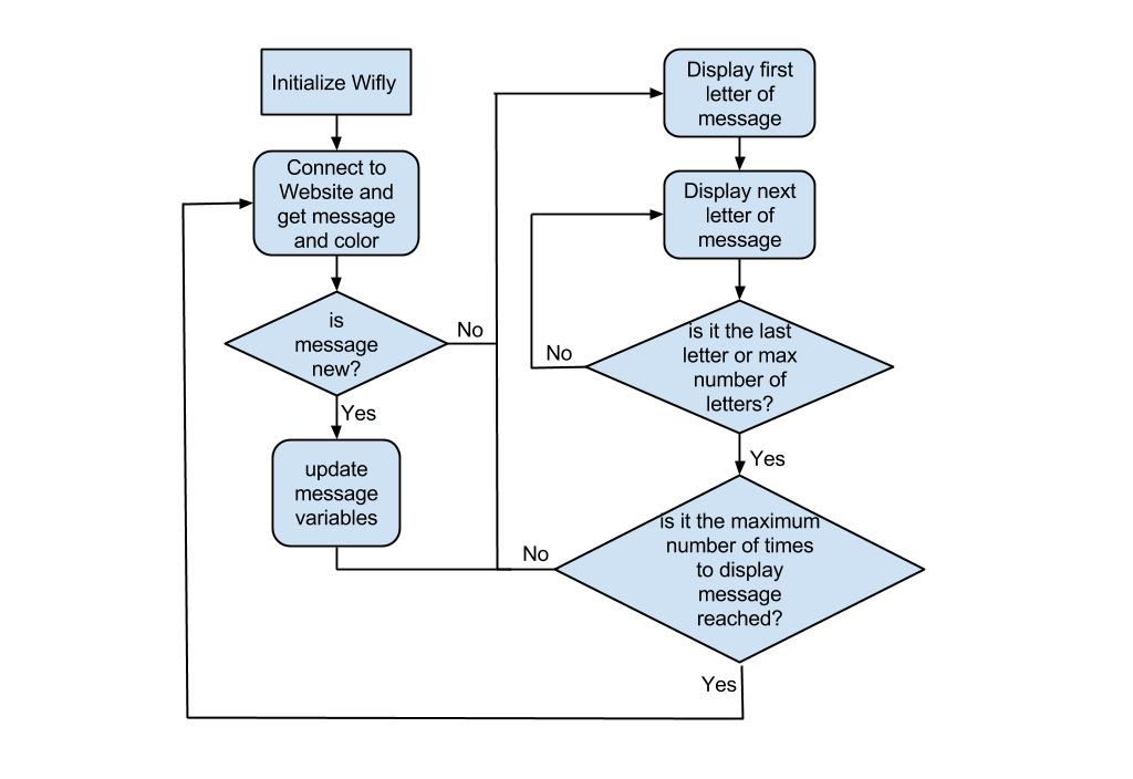
The system then logs into the website to check the message and color set by the user. The message is then compared to the message actively being displayed (if any) and if it is different it will update the message being displayed. The system then will start displaying the message by communicating to the LED strip using the SPI protocol. The controller will set the values for each individual LED (wether they are on or off and the color), Each letter of the message will be displayed. After the message has been displayed completely 200 times the system will connect to the webpage to verify if there is a new message and the loop will repeat. See Figure below for the flow diagram.
Website
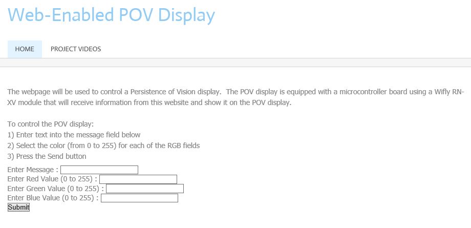
A website has been designed to receive the user input. The website is hosted by iPage and the domain is www.povdisplay.com. The website will allow the end user to submit a message and RGB color values to display on the device. The website will use php code and a MySQL database to store the user input. The wifly module will poll the website to receive the data.
A screenshoot of the website is shown below.
The php file called by the wifly module is called printinput.php. A screenshot showing the example data is shown below.
Testing & Technical Challenges
- Building the Mechanical device was a challenge. The device needed to be precisely balanced in order to spin in a stable manner
- Wifi connection issues. The documentation for the Wifly RN-XV module was difficult to follow. Also some group members had routers that did not accept the connection.
- Synchronization of the LEDs with the motor speed. The motor did not spin at a constant rate. A sensor is needed to allow the software to compensate for the inconsistencies in the motor.
Future Improvements
- Stabilize display refresh using Hall Effect Sensor
- Expand the radius of the device to display a longer message. Also can consider expanding to more LEDs (currently 14)
- Addition of various text effects
- Add the capability to display a bitmap image
Conclusion
This was a fun project to complete. It was rewarding to produce a device that could be controlled by anyone with an internet connection. The team worked well together and learned a lot about the SJSU board and how to use it. In addition, the team got experience building a webpage, writing php code, using the WIfly module, wiring and driving the LEDs. and writing C++ drivers. Probably the biggest challenge of all was building the mechanical device itself.
Project Video
Project Photos
Project Source Code
References
[1] http://www.identifont.com/similar?1SS
[2] http://en.wikipedia.org/wiki/Persistence_of_vision
[3] https://github.com/cjbaar/LPD8806
[4] https://solarbotics.com/download.php?file=1889
[5] http://www.wayjun.com/Datasheet/Led/5050%20SMD%20LED.pdf
[6] Preet's Sprinkler System Code
[7] Wifly User Manual


