Difference between revisions of "S18: Death Race"
Proj user7 (talk | contribs) (→Software Design) |
Proj user7 (talk | contribs) (→Team Members & Responsibilities) |
||
| (271 intermediate revisions by the same user not shown) | |||
| Line 1: | Line 1: | ||
| − | + | [[File:WhatsApp_Image_2018-05-26_at_1.12.40_AM.jpeg|thumb|1100x600px|right|Death Race]] | |
| − | + | ||
| − | + | ||
| − | |||
| − | |||
| − | |||
| − | |||
| − | |||
| − | |||
| − | |||
| − | |||
== Project Title == | == Project Title == | ||
| + | |||
==== Death Race - A car racing game using FreeRTOS ==== | ==== Death Race - A car racing game using FreeRTOS ==== | ||
| − | |||
Git Link - [https://gitlab.com/Magnumopus244/DeathRace]<br> | Git Link - [https://gitlab.com/Magnumopus244/DeathRace]<br> | ||
== Abstract == | == Abstract == | ||
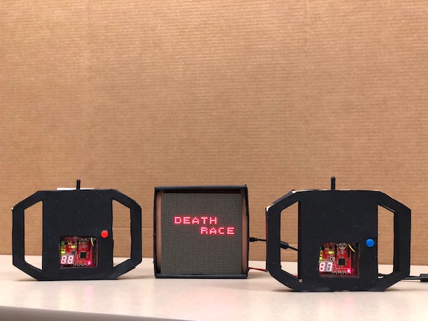
| − | Real-time adaptation of computer games can content the users’ abilities, skills and also enhance the players' engagement and immersion. | + | Real-time adaptation of computer games can content the users’ abilities, skills and also enhance the players' engagement and immersion. This led us to design a car racing game between two players. There will be car-race tracks for each player and the player can shift horizontally on the track. The players can move horizontally on the track (RGB LED Matrix Display) by tilting the Player consoles (SJone boards), either left or right. Each player will encounter two kinds of obstacles during the game- square and triangular obstacles. The score of the player is incremented for collecting the square boxes and decremented every time when it hits the triangular obstacles. The obstacles are generated randomly and the criticality of the game (randomness of obstacles) increases with time. The individual player score will be displayed and updated from time to time on the LCD Display Matrix. The game ends at the end of 60 seconds and last 10 seconds of the game are indicated by changing the color of the score to red and blinking them. The player with a greater score wins the game. |
== Objectives & Introduction == | == Objectives & Introduction == | ||
| − | |||
| + | [[File:Top_Architecture.png|thumb|600x364px|right|Top Architecture]] | ||
=== Introduction === | === Introduction === | ||
| Line 28: | Line 20: | ||
'''1) Player Module: ''' Two SJOne boards simultaneously sending accelerometer data to the Master Board via Nordic wireless. | '''1) Player Module: ''' Two SJOne boards simultaneously sending accelerometer data to the Master Board via Nordic wireless. | ||
| − | '''2) Wireless: ''' Communication bridge between the player module and the Master module. | + | '''2) Wireless Module: ''' Communication bridge between the player module and the Master module. |
| + | |||
| + | '''3) Master Module: ''' The master module is responsible for getting the player movement and designing the algorithm of the car video game | ||
| + | |||
| + | '''4) Display Module: ''' The module is responsible for controlling and updating the LED on display matrix | ||
| − | + | ==== About the game ==== | |
| + | * 2-Player Car Racing Game | ||
| + | * 60 seconds game timer | ||
| + | * Press switch on the console (SJOne board) to start | ||
| + | * Tilt the console left or right to move the car | ||
| + | * Collect square obstacles | ||
| + | * Avoid triangular obstacles | ||
| + | * Higher score player wins after the timeout | ||
| − | |||
=== Objectives === | === Objectives === | ||
| − | === Team Members & Responsibilities === | + | ==== Team Members & Responsibilities ==== |
| − | * Player Module | + | * '''Player Module''' |
| + | **'''''[https://www.linkedin.com/in/rajvisharia Raj Visharia]''''' | ||
| + | * '''Display (RGB LED Matrix)''' | ||
**'''''[https://www.linkedin.com/in/rajvisharia Raj Visharia]''''' | **'''''[https://www.linkedin.com/in/rajvisharia Raj Visharia]''''' | ||
**'''''[https://www.linkedin.com Supradeep Koganti]''''' | **'''''[https://www.linkedin.com Supradeep Koganti]''''' | ||
| − | * Wireless (Nordic) | + | * '''Wireless (Nordic)''' |
**'''''[https://www.linkedin.com/in/hemant-banjara-89a41b58/ Hemant Banjara]''''' | **'''''[https://www.linkedin.com/in/hemant-banjara-89a41b58/ Hemant Banjara]''''' | ||
| − | * Master Module | + | * '''Master Module''' |
**'''''[https://www.linkedin.com Rahul Devaragudde Gopala]''''' | **'''''[https://www.linkedin.com Rahul Devaragudde Gopala]''''' | ||
**'''''[https://www.linkedin.com Sneha Shahi]''''' | **'''''[https://www.linkedin.com Sneha Shahi]''''' | ||
| − | + | * '''PCB''' | |
| − | + | **'''''[https://www.linkedin.com Rahul Devaragudde Gopala]''''' | |
| − | |||
| − | |||
| − | **'''''[https://www.linkedin.com Rahul Devaragudde Gopala | ||
| − | |||
| − | |||
| − | |||
== Schedule == | == Schedule == | ||
| − | + | ||
{| class="wikitable" | {| class="wikitable" | ||
| Line 198: | Line 196: | ||
== Parts List & Cost == | == Parts List & Cost == | ||
| − | + | ||
{| class="wikitable" | {| class="wikitable" | ||
| Line 227: | Line 225: | ||
|- | |- | ||
! scope="row"| 4 | ! scope="row"| 4 | ||
| − | | Level Shifter SN74AHCT245N | + | | Level Shifter (SN74AHCT245N) |
| Mouser Electronics [https://www.mouser.com/ProductDetail/texas-instruments/sn74ahct245n/?qs=dQtLEVC3WoaJCroya2tnJw%3d%3d&countrycode=US¤cycode=USD] | | Mouser Electronics [https://www.mouser.com/ProductDetail/texas-instruments/sn74ahct245n/?qs=dQtLEVC3WoaJCroya2tnJw%3d%3d&countrycode=US¤cycode=USD] | ||
| 2 | | 2 | ||
| Line 249: | Line 247: | ||
| 3 | | 3 | ||
| $0 | | $0 | ||
| + | |- | ||
| + | ! scope="row"| 8 | ||
| + | | Cardboard | ||
| + | | Spartan Shop | ||
| + | | 1 | ||
| + | | $4 | ||
| + | |- | ||
| + | ! scope="row"| 9 | ||
| + | | Scissors & glue | ||
| + | | Spartan Shop | ||
| + | | 1 | ||
| + | | $2 | ||
|- | |- | ||
|} | |} | ||
== Design & Implementation == | == Design & Implementation == | ||
| − | |||
| − | |||
== Player Module == | == Player Module == | ||
| Line 260: | Line 268: | ||
=== Hardware Design === | === Hardware Design === | ||
| − | |||
'''Accelerometer''' | '''Accelerometer''' | ||
| Line 267: | Line 274: | ||
By incorporating more intelligence from movements and tilt positions, the accelerometers have had a significant impact on user interaction. Most motion-based games are derived from analyses of static acceleration, which are based on gravity to determine the change in tilt angles. Accelerometers provide a new way for navigating, scrolling, and displaying information and thus, provide entertainment in motion-based games. In this project, accelerometer changed the design of the Player Module by minimizing the need for buttons on the board and including motion inputs. | By incorporating more intelligence from movements and tilt positions, the accelerometers have had a significant impact on user interaction. Most motion-based games are derived from analyses of static acceleration, which are based on gravity to determine the change in tilt angles. Accelerometers provide a new way for navigating, scrolling, and displaying information and thus, provide entertainment in motion-based games. In this project, accelerometer changed the design of the Player Module by minimizing the need for buttons on the board and including motion inputs. | ||
| + | |||
=== Hardware Interface === | === Hardware Interface === | ||
| Line 276: | Line 284: | ||
angle = sin(z/x) where, x = X-axis values of the accelerometer | angle = sin(z/x) where, x = X-axis values of the accelerometer | ||
z = Z-axis values of the accelerometer | z = Z-axis values of the accelerometer | ||
| + | |||
| + | This angle value is used to determine the tilt of the board. Depedning upon the tilt, either left, right, straight or invalid is send wirelessly to the master module. | ||
| + | * Right condition : (angle = 0) and (x < 0) | ||
| + | * Straight condition : (-1 < angle < 1) & (angle != 0) and (z > 0) | ||
| + | * Left condition : (angle = 0) and (x > 0) | ||
| + | * Invalid condition : Any other orientation | ||
| + | |||
=== Software Design === | === Software Design === | ||
| − | + | Following is the software flowchart followed for player module | |
| + | [[File:Swplayer.png|thumb|427x440px|center|Software Flow]] | ||
| + | == Nordic Wireless == | ||
| + | We have used Nordic Wireless communication to send the ready status and orientation of player1 and player2 to Master. The mesh network drivers were used to interface with the Nordic IC. The Nordic nRF24L01+ is a highly integrated, ultra low power 2Mbps RF transceiver IC for the 2.4GHz ISM (Industrial, Scientific and Medical) band. The Nordic nRF24L01+ integrates a complete 2.4GHz RF transceiver, RF synthesizer, and baseband logic. We had to attach a RP-SMA Connector antenna to communicate between the multiple nodes. Nordic wireless can be used in multiple applications such as smart homes, games, consumer electronics and PC peripherals. We made use of Preet’s Low Powered Mesh Network stack. | ||
| + | Each packet is sent via an existing route, and if route has changed, a new route is automatically discovered using a special retry packet. Each node's ACK contains some meta-data about the node itself. This data includes information about its routing table, and other statistic. Duplicate packets are absorbed but an ACK is still replied if it's a duplicate, but a retry packet. An ACK packet or a response to an ACK all use retries; even the repeating nodes participate to make sure the packet is delivered. The minimum payload is 9 bytes, of which, 8 bytes will be the mesh header overhead. The higher the payload, the higher the efficiency of the network. The eight bytes of payload header contains the network source and destination information, along with packet type and hop count information. | ||
| − | + | For example, if the payload size is 32 bytes, then 8 bytes are used by the network header and 24 bytes are free to be used for transmitting the data. | |
| − | + | The mesh_packet_t is a structure that is used to transmit the data to understand the data of the wireless packet. It has 4 struct variables. | |
| − | + | ||
| + | nwk : Packet network address | ||
| + | |||
| + | mac : packet physical address | ||
| + | |||
| + | info:Packet header | ||
| + | |||
| + | Data:uint8_t type of data that is sent.. | ||
| − | + | In this example, both the player boards send the ready status and orientation to master. After getting ready status from both the players game will start and then master start receiving the orientation.Furthermore, we show you how data variables can be exchanged between two boards. A wireless Tx task was created which was used to handle the wireless Nordic transmissions. | |
=== Hardware Design === | === Hardware Design === | ||
| − | + | The Nordic wireless is connected over SPI lines on SJone board | |
| + | |||
| + | === Software Design === | ||
| + | |||
| + | Here are some of the Nordic wireless API we used for our project. | ||
| + | |||
| + | 1. This function is responsible to send the packet wherein the address of the destination node, type of mesh protocol used, pointer to the data to send, length of the data to send and number of hops is passed as a parameter. It returns true if packet is sent successfully. | ||
| + | |||
| + | wireless_send(Master_Rx_Address, mesh_pkt_nack, &steer, sizeof(steer), 0) | ||
| + | |||
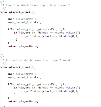
| + | 2. This function is periodically called to get a queued packet. It takes variable of type mesh_packet_t to store the received packet and queue wait time. It returns true if a packet is dequeued or false if there is no packet. | ||
| + | |||
| + | wireless_get_rx_pkt(&rcvPkt, timeout_ms) | ||
| + | |||
| + | [[File:Webp.net-resizeimage (1).png|thumb|600x600px|right|Nordic Software Flow Chart]] | ||
| + | [[File:Trans1.PNG|thumb|500x64px|left|Transmitter code]] | ||
| + | [[File:Rec.PNG|thumb|600x600px|left|Reciever code]] | ||
| + | |||
| + | |||
| + | |||
| + | |||
| + | |||
| + | |||
| + | |||
| + | |||
| + | |||
| + | |||
| + | |||
| + | |||
| + | |||
| + | |||
| + | |||
| + | |||
| + | |||
| + | |||
| + | |||
| + | |||
| + | |||
| + | |||
| + | |||
| + | |||
| + | |||
| + | |||
| + | |||
| + | |||
| + | |||
| + | |||
| + | |||
| + | |||
| + | |||
| + | |||
| + | |||
| + | |||
| + | |||
| + | |||
| + | |||
| + | |||
| + | |||
| + | |||
| + | |||
| + | |||
| + | |||
| + | |||
| + | |||
| + | |||
| + | |||
| − | |||
| − | |||
| − | |||
| − | |||
| − | == | + | == RGB LED Display Matrix Module == |
| − | + | For the User Interface, a 64x64 LED Display Matrix has been used in this project. It has 5 address lines an | |
| + | Other specifications of 64x64 RGB LED Matrix are as follows: | ||
| + | * Brightness: 2800cd/square meter | ||
| + | * Size: 160x160mm | ||
| + | * Pitch: 2.5M | ||
| + | * 5 Addressable Pins | ||
| + | * Scan: 1/32 | ||
| + | * Refresh Frequency: >=400HZ | ||
| + | * Waterproof Class: IP43 | ||
| + | * Weight: 204.8g (only matrix panel). | ||
| − | |||
=== Hardware Design === | === Hardware Design === | ||
| − | + | ||
| + | SJOne board GPIO pins output 3.3V. However, to drive the RGB LED Display Matrix we need 5V. So, 3.3V from the SJOne Board is converted to 5V using 2 level shifters as shown in the pin connection diagram below: | ||
| + | [[File:Picture1.png|thumb|800x800px|center|RGB LED Display Matrix Pin Connections]] | ||
| + | |||
| + | |||
| + | === LED Matrix Control === | ||
| + | |||
| + | [[File:Capture.JPG|thumb|500x453px|left|]] | ||
| + | [[File:Capture2.JPG|thumb|450x369px|center|]] | ||
| + | [[File:Capture0.JPG|thumb|500x350px|left|]] | ||
| + | [[File:Capture123.JPG|thumb|455x400px|center|]] | ||
| + | [[File:Capture3.JPG|thumb|600x218px|center|]] | ||
| + | |||
=== Hardware Interface === | === Hardware Interface === | ||
| − | + | The RGB LED Display Matrix gets the input from Master Module (SJOne board). It is driven by the GPIO Pins of the Master Module. However, these GPIO pins are not connected directly to the display matrix since 64x64 RGB LED Matrix drives on 5V input whereas the GPIO pins from SJOne board output 3.3V. So, two level shifter ICs are used as an intermediate connection to convert 3.3V GPIO output from SJOne board to 5V before giving it as an input to the RGB Led Matrix. | |
| + | |||
| + | This 64x64 LED matrix has 5 address lines viz. A, B, C, D, E. With 5 address lines, we get 2^5 = 32 unique addresses. But, the matrix has 64 rows. | ||
| + | The scan rate of the LED Matrix is 1/32, i.e., 2/64. This indicates that by making each address line high, two rows will be driven at the same time. | ||
| + | |||
| + | [[File:LED_Matrix_Division.jpg|thumb|371x272px|left|RGB LED Display Matrix]] | ||
| + | |||
| + | |||
| + | The LED display Matrix is divided into two sections- | ||
| + | * Section 1 - First 32 rows (Row 0 to row 31) | ||
| + | * Section 2 - Remaining 32 rows (Row 32 to row 63) | ||
| + | |||
| + | 6 data lines, 3 for each section are available to drive the RGB matrix. | ||
| + | * R1, G1, B1 - For section 1 | ||
| + | * R2, G2, B2 - For section 2 | ||
| + | |||
| + | Other pins: | ||
| + | * OE - Output Enable | ||
| + | * Lat - Latch | ||
| + | * Clk - clock signal | ||
| + | * Vcc - High Voltage (5V) | ||
| + | * Gnd - Ground (0V) | ||
| + | |||
| + | |||
| + | |||
=== Software Design === | === Software Design === | ||
| − | + | ||
| + | Entire driver function for RGB LED Matrix APIs was self-written from scratch. | ||
| + | |||
| + | Logic: | ||
| + | In order to save the memory, a buffer of size 32x64 used instead of using 64x64 buffer and updated every 1ms. This buffer stores the pixel values of the RGB LED matrix and updates them every 1ms. A variable of 8-bits is stored in each cell, where the first two MSB bits are not used and the remaining 6-bits represent 6 RGB data lines as: (X X R2 G2 B2 R1 G1 B1). | ||
| + | uint8_t matrixbuff[MATRIX_NROWS][MATRIX_HEIGHT]; where, MATRIX_NROWS = 32 | ||
| + | MATRIX_HEIGHT = 64 | ||
| + | uint8_t pixel_value-> X X R2 G2 B2 R1 G1 B1 | ||
| + | |||
| + | |||
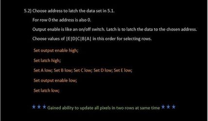
| + | In order to drive only one row, particular address lines can be made high and enabling the RGB pins for the section in which that row lies. For example, to glow the first row (row 0) red, ABCDE = 00001 and R1 = 1. All other RGB pins should be made 0. | ||
| + | With the combination of address lines and 6 RGB pins, any particular row with a specific color can be displayed. | ||
| + | |||
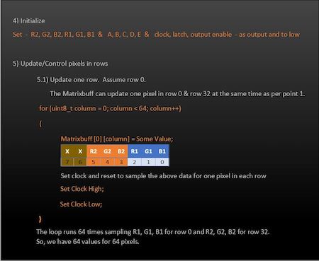
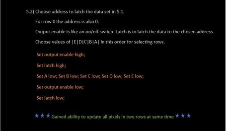
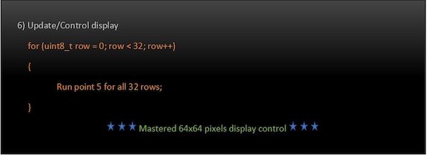
| + | In order to update a single LED pixel value, set the variable (X X R2 G2 B2 R1 G1 B1) conditions to update the matrix buffer, and then set the clock high and low (to indicate one clock pulse). Repeat this process for as many columns present in the matrix. After this, set the output enable and latch pins high. Now, set the address lines depending upon the values set in the row number. After doing this, set the latch and output enable pins low. And then repeat this process for as many times as the number of rows (in our case, the row number is 64 but, since the matrix buffer is selected as 32 to save memory by dividing into two sections, it will be 32). In this way the pixel values are set high or low and stored in the buffer. The updateBuffer() function is called every 1ms to update the LED matrix display. | ||
| + | |||
| + | |||
| + | [[File:UpdateDisplay1.JPG|thumb|396x516px|left|Update Display Function]] | ||
| + | [[File:UpdateDisplay2.JPG|thumb|365x516px|center|Update Display Function continued..]] | ||
| + | |||
| + | Depending upon the different values that can be stored in each cell value, an enum is used to represent different color values as shown in the below image. This helps the Master module to directly pass any color value from the enum in order to display a specific color and in a specific section of the LED Matrix Display. | ||
| + | For example: If the Master wants to display the car for Player 1 (Player 1 is represented by red color and is in section 1) starting from position (24, 2), then it just has to call the display API function as follows: | ||
| + | drawCar(24, 2, red1); Note: red1 = 4 (00000100) -> R1 is set. | ||
| + | |||
| + | Similarly, if the Master wants to display the car for Player 2 (Player 2 is represented by blue color and is in section 2) at (55, 2), then it can be displayed by calling the same function | ||
| + | drawCar(24, 2, red2); Note: red2 indicates that we want to display in Section 2. | ||
| + | red2 = 32 -> (00100000) -> R2 is set. | ||
| + | x = 55 in the display corresponds to x=24 for section 2. | ||
| + | |||
| + | To display red cars at the specified location on both the sections at the same time, | ||
| + | drawCar(24, 2, red); Note: red = 36 (00100100) -> R1 & R2 are set. | ||
| + | |||
| + | Also, each pixel values can be updated using drawPixel() or clearPixel() functions. | ||
| + | |||
| + | [[File:RGB_Enum_.JPG|thumb|442x506px|left|Color_code enum]] | ||
| + | [[File:Capture1.JPG|thumb|433x249px|right|Functions to draw or clear Pixel values]] | ||
| + | |||
| + | |||
| + | |||
| + | |||
| + | |||
| + | |||
| + | |||
| + | |||
| + | |||
| + | |||
| + | |||
| + | |||
| + | |||
| + | |||
| + | |||
| + | |||
| + | |||
| + | |||
| + | |||
| + | |||
| + | |||
| + | |||
| + | |||
| + | |||
| + | |||
| + | |||
| + | |||
| + | |||
| + | |||
| + | |||
| + | |||
| + | |||
| + | |||
| + | |||
| + | |||
| + | |||
| + | |||
| + | |||
| + | |||
| + | |||
| + | |||
| + | |||
| + | |||
| + | |||
| + | |||
| + | |||
| + | |||
| + | Functions like moving the display down to get real-time game feel (making sure that score displayed on the top remains intact) was a challenging task but, not impossible. It was carried out by updating the matrix updating the pixel value by copying the value above it and doing this for each pixel in a column and subsequently for all the rows to cover the entire matrix. | ||
| + | matrixbuff[x][y] = matrixbuff[x][y+1]; | ||
| + | The play area above 53rd column (col=52) was uncahnged as it was reserved to display the scores. The topmost pixel value to be moved down in this application was the 53rd pixel in each row. It was cleared and all other pixel values below it were moved down. | ||
| + | However, challenging part was to generate dotted lane marking lines at every interval while moving the display down. In the rows corresponding to these lane markings (x=10 and x=21), pixels were cleared for count equal to 4 and 5 and they were set otherwise and count made to zero after count = 5. Thus, this gave us dotted lane lines (2 pixels cleared after every 3 pixels set) at rows 11 and 22 while moving the display down. | ||
| + | |||
=== Implementation === | === Implementation === | ||
| − | |||
| + | Various functions were written to display pixels, lines (dotted or solid), digits, numbers, time, text, cars, obstacles as well as to clear them. Also, APIs to check if the player hit the obstacle or no and to display the starting condition and winner of the game were written. These APIs are called by the Master module to carry out specific tasks and check conditions depending upon the values obtained from the player module. | ||
| + | Below diagram shows the functions in the display matrix API | ||
| + | |||
| + | [[File:Led_h_file_pic.JPG|thumb|715x598px|center| LED Display Matrix API]] | ||
== Master Module == | == Master Module == | ||
| + | The master module takes care of implementing the algorithm of game and driving the RGB LED matrix | ||
| + | === Hardware Design === | ||
| − | + | The master module takes orientation input from two players through Nordic wireless. After taking the inputs from the wireless sensor the master module implements the algorithm to drive the simulated car on RGB LED matrix. The algorithm | |
| − | + | checks for the collision of car with the obstacles. If the car collides with square obstacles then the score gets incremented and if it collides with triangular obstacle then the score is decremented. It checked for timer and as 60 seconds get over it decide the winner based on the score and display the winner | |
=== Hardware Interface === | === Hardware Interface === | ||
| − | + | The following diagram represents the hardware interface and hardware protocol used for the communication. | |
| + | [[File:Hardware_protocol.png|thumb|427x250px|center|Hardware Design]] | ||
=== Software Design === | === Software Design === | ||
| − | + | ||
| + | The Master application file consists of 5 tasks Init, Display update, layout design obstacle generation, Player1 task and Player2 task. As soon as the application starts, the Init task does the Gpio configuration of the RGB led matrix, put the initial graphics on the matrix and would wait for Player to send the start signal. Once the players send the start signal then the other task layout, obstacle, and players task start to run.Player1 and player2 task takes care of car movement for triangular obstacle avoidance and hitting the square obstacle.The obstacle generates obstacle for all the three paths for player.The obstacle voidance and display update task has higher priority than the player task. | ||
| + | [[File:MASTERSW.png|thumb|619x495px|center|Software Flow]] | ||
=== Implementation === | === Implementation === | ||
| − | + | FreeRtos API was used were used for the implementation of the master module. | |
| + | Following approach were followed for the implementation | ||
| + | |||
| + | 1. The function with the same functionality and had the same code for example both the players were kept in two different task of equal priority | ||
| + | |||
| + | 2. The update Display task which refreshes the buffer of LED Matrix was kept at the higher priority than the player task with vTaskdelay of 1 ms. | ||
| + | |||
| + | 3. The obstacle generation task was kept at the same priority as of update display task. | ||
| + | |||
| + | 4. The start display pages to show that both the players are ready were kept in one task and the task was suspended once the game starts to save CPU cycles | ||
| + | |||
| + | == PCB Design == | ||
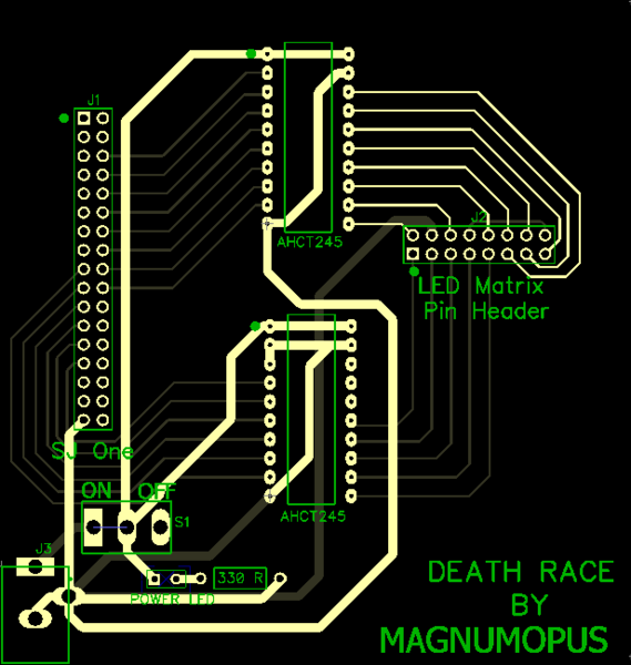
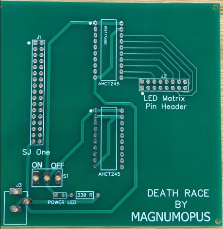
| + | The Printed Circuit Board design was done using Dip Trace open-source software. The software design tool provides drag and drop functionalities using which we created our own design. The connections are divided between top and bottom layers to ensure that the design rule conditions are not violated. | ||
| + | [[File:PCB Final.png|thumb|569x600px|left|PCB Layout]] | ||
| + | [[File:PCB_Board.JPG|thumb|459x473px|right|Actual Board]] | ||
| + | |||
| + | |||
| + | |||
| + | |||
| + | |||
| + | |||
| + | |||
| + | |||
| + | |||
| + | |||
| + | |||
| + | |||
| + | |||
| + | |||
| + | |||
| + | |||
| + | |||
| + | |||
| + | |||
| + | |||
| + | |||
| + | |||
| + | |||
| + | |||
| + | |||
| + | |||
| + | |||
| + | |||
| + | |||
| + | |||
| + | |||
| + | |||
| + | |||
| + | |||
| + | |||
| + | |||
| + | |||
| + | |||
| + | |||
| + | |||
| + | |||
| + | |||
| + | |||
| + | |||
| + | |||
| + | |||
| + | |||
| + | |||
| + | |||
| + | |||
| + | |||
| + | |||
== Testing & Technical Challenges == | == Testing & Technical Challenges == | ||
| − | |||
| − | |||
| − | + | ===Issues and Challenges=== | |
| + | |||
| + | '''1. No Datasheet''' | ||
| + | |||
| + | There is no datasheet available for the 64x64 RGB Led Display Matrix. So, we had to read the other LED matrix module datasheets and analyze the data and addressing scheme for our matrix module. | ||
| + | |||
| + | '''2. Designing the RGB LED Matrix Display driver''' | ||
| + | |||
| + | Writing the driver function on our own was a challenge. We were able to easily glow a single row in the matrix. However, the challenge lied in glowing a single pixel value at a specified location. And lack of datasheet made it even more difficult. Once we got the control over glowing a single LED (check updateDisplay function as shown above), we were able to implement various functions to draw lines, squares, triangles, car, digits, text. | ||
| + | |||
| + | '''3. Matrix flickering Issue''' | ||
| + | |||
| + | The application has a task to call updateDisplay() function to update the buffer every 1ms. This task had a lower priority as compared to the player transaction task in the Master module. As a result of this, the LED Display Matrix was being updated at a slower rate, and thus, leading to matrix flickering. The issue was resolved by changing the priority of the updateDisplay matrix task higher than the Player task. | ||
| + | |||
| + | '''4. Wireless Packet drop''' | ||
| + | |||
| + | The Player module was waiting for acknowledgment from the master module which delayed the sending of the orientation data. Since, the player must keep on continuously send the orientation data irrespective of the acknowledgment received from the Master board, the logic to wait for acknowledgment was removed and packet drop reduced significantly. This led to the smooth movement of the car on the display as Master started receiving continuous data from the Player module. | ||
| + | |||
| + | '''5. Wireless noise interference''' | ||
| + | |||
| + | We tried different channels from 2400-2499 and picked the channel number 2499 as it was giving the least noise interference in the communication between our Player boards and the Master board. | ||
| + | |||
| + | === Testing === | ||
| + | |||
| + | '''1. Calling display API functions in tasks as opposed to calling in main''' | ||
| + | |||
| + | Various functions were written in Display Matrix module and tested. This functions can be directly called in main and checked on the display. However, to avoid issues during integration with the master, which ran multiple tasks by checking the logic, the display matrix functions were called by running multiple tasks in Display Matrix module and tested there itself. After which they were integrated with Master module. So, if multiple tasks calling these functions had issues, then it could be resolved right away before integrating with the Master module. | ||
| − | + | ''' 1. Feature by Feature testing''' | |
| − | |||
| + | We tested the application as soon as we completed one feature. As soon as a function was written bY Display Matrix members, it was tested on the display. Further, it was integrated with the Master module tasks and tested. This helped a lot in debugging the issues while integrating. | ||
== Conclusion == | == Conclusion == | ||
| − | + | We were able to successfully design a 2-player car racing game using RGB LED Matrix. This project helped us gain a working knowledge of FreeRTOS tasks and how to write drivers. Along the course of the project, we faced many hardware and software issues, especially while integrating a new module into the existing working solution. But, in spite of all the difficulties, we were able to achieve our goal with the help of proper understanding and teamwork. Working in a group and managing schedules, it felt as if we were doing an internship. Overall, it was a great learning experience which molded us into better than what we were before we started. | |
| + | |||
| + | * '''Team Work:''' Working in a team with different people gave us the industry experience. There were quite a lot of time when we did not agree which lead to discussions and logical reasoning to come to a consensus decision. | ||
| + | |||
| + | * '''GIT:''' Our source code versioning, code review sessions and test management were done using GIT. | ||
| + | |||
| + | * '''Debugging:''' We followed the debugging technique discussed by Preet in the class. When we have multiple tasks and have to figure out which task is the culprit, we must comment the task which is working fine, making sure it still fails. And keep doing this until the culprit task is found out. This helped a lot in debugging the master module as it had lots of tasks implemented. | ||
=== Project Video === | === Project Video === | ||
| − | Game Video - [https:// | + | Game Video - [https://youtu.be/jbGvOdyTFEc Death Race] |
=== Project Source Code === | === Project Source Code === | ||
Git - [https://gitlab.com/Magnumopus244/DeathRace Death Race by Magnum Opus]<br> | Git - [https://gitlab.com/Magnumopus244/DeathRace Death Race by Magnum Opus]<br> | ||
| − | |||
== References == | == References == | ||
=== Acknowledgement === | === Acknowledgement === | ||
| − | + | ||
| + | We would like to thank our professor, Preetpal Kang for designing such a course where learning was his guidance and consistent feedback. We would also like to thank the ISA team for their valuable inputs, support and motivation whenever needed. Finally, the credit goes to our entire team, Magnumopus. With full support and cooperation from each other, we were successfully able to complete this project as planned. It was a matter of hardships and sleepless nights but, the amount of knowledge and experience gained was worth the struggle. In the end, the praise from the professor and other peers after the presentation were inspiring and we look forward to further optimize the project and add more features. | ||
=== References Used === | === References Used === | ||
| − | + | [1] [https://www.adafruit.com/product/3649 Adafruit 64x64 RGB LED Matrix] | |
| + | |||
| + | [2] [http://www.rayslogic.com/propeller/Programming/AdafruitRGB/AdafruitRGB.htm Adafruit RGB LED Matrix] | ||
| + | |||
| + | [3] [https://www.sparkfun.com/sparkx/blog/2650 Everything You Didn't Want to Know About RGB Matrix Panels] | ||
| + | |||
| + | [4] [https://www.marutsu.co.jp/contents/shop/marutsu/ds/DFR0499_Web.pdf Marutsu - RGB Pin Configuration] | ||
| + | |||
| + | [5] [https://github.com/adafruit/Adafruit-GFX-Library Adafruit Github Library] | ||
| + | |||
| + | [6] [https://www.google.co.in/imgres?imgurl=https%3A%2F%2Fcdn.instructables.com%2FFLN%2F05VC%2FG68HDRBT%2FFLN05VCG68HDRBT.LARGE.jpg&imgrefurl=http%3A%2F%2Fwww.instructables.com%2Fid%2FLED-Scolling-Dot-Matrix-Font-Graphics-Generator-%2F&docid=NuWKN2ZnFWDO1M&tbnid=7zNhnJrA8B_lcM%3A&vet=10ahUKEwjR-vuj4ZLbAhWphlQKHY2LCPMQMwg_KAAwAA..i&w=317&h=301&bih=637&biw=1366&q=8x5%20alphabets%20for%20led%20display&ved=0ahUKEwjR-vuj4ZLbAhWphlQKHY2LCPMQMwg_KAAwAA&iact=mrc&uact=8#h=301&imgdii=2mlyw3wI6R48vM:&vet=10ahUKEwjR-vuj4ZLbAhWphlQKHY2LCPMQMwg_KAAwAA..i&w=317 LED Text Image] | ||
| + | |||
| + | [7] [https://www.sparkfun.com/datasheets/Components/SMD/nRF24L01Pluss_Preliminary_Product_Specification_v1_0.pdf Nordic Datasheet] | ||
| + | |||
| + | [8] [https://www.freertos.org/ FreeRTOS] | ||
=== Appendix === | === Appendix === | ||
| − | |||
Latest revision as of 18:10, 4 August 2018
Contents
Project Title
Death Race - A car racing game using FreeRTOS
Git Link - [1]
Abstract
Real-time adaptation of computer games can content the users’ abilities, skills and also enhance the players' engagement and immersion. This led us to design a car racing game between two players. There will be car-race tracks for each player and the player can shift horizontally on the track. The players can move horizontally on the track (RGB LED Matrix Display) by tilting the Player consoles (SJone boards), either left or right. Each player will encounter two kinds of obstacles during the game- square and triangular obstacles. The score of the player is incremented for collecting the square boxes and decremented every time when it hits the triangular obstacles. The obstacles are generated randomly and the criticality of the game (randomness of obstacles) increases with time. The individual player score will be displayed and updated from time to time on the LCD Display Matrix. The game ends at the end of 60 seconds and last 10 seconds of the game are indicated by changing the color of the score to red and blinking them. The player with a greater score wins the game.
Objectives & Introduction
Introduction
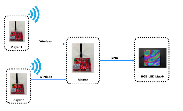
The project was divided into 4 main modules:
1) Player Module: Two SJOne boards simultaneously sending accelerometer data to the Master Board via Nordic wireless.
2) Wireless Module: Communication bridge between the player module and the Master module.
3) Master Module: The master module is responsible for getting the player movement and designing the algorithm of the car video game
4) Display Module: The module is responsible for controlling and updating the LED on display matrix
About the game
- 2-Player Car Racing Game
- 60 seconds game timer
- Press switch on the console (SJOne board) to start
- Tilt the console left or right to move the car
- Collect square obstacles
- Avoid triangular obstacles
- Higher score player wins after the timeout
Objectives
Team Members & Responsibilities
- Player Module
- Display (RGB LED Matrix)
- Wireless (Nordic)
- Master Module
- PCB
Schedule
| Week# | Date | Task | Status |
|---|---|---|---|
| 1 | 03/04 |
|
|
| 2 | 03/11 |
|
|
| 3 | 03/18 |
|
|
| 4 | 03/25 |
|
|
| 5 | 04/01 |
|
|
| 6 | 04/08 |
|
|
| 7 | 04/15 |
|
|
| 8 | 04/22 |
|
|
| 9 | 04/29 |
|
|
| 10 | 05/06 |
|
|
| 11 | 05/13 |
|
|
| 12 | 05/20 |
|
|
Parts List & Cost
| Item# | Part Desciption | Vendor | Qty | Cost |
|---|---|---|---|---|
| 1 | SJOne Boards | From Preet | 3 | $240.00 |
| 2 | 64x64 RGB LED Matrix | Adafruit | 1 | $92.00 |
| 3 | Power Cable | Amazon | 1 | $20 |
| 4 | Level Shifter (SN74AHCT245N) | Mouser Electronics [2] | 2 | $21.95 |
| 5 | PCB | PCBWay [3] | 4 | $27 |
| 6 | IC Base | Fry's Electronics | 2 | $2 |
| 7 | Antennas | From Preet | 3 | $0 |
| 8 | Cardboard | Spartan Shop | 1 | $4 |
| 9 | Scissors & glue | Spartan Shop | 1 | $2 |
Design & Implementation
Player Module
Player Module is responsible for sending the accelerometer sensor values from the two player consoles (SJOne boards) to the Master Module (SJOne board) in order to horizontally move the cars left or right of respective players on the display (RGB LED Display Matrix).
Hardware Design
Accelerometer
SJOne board has MMA8452Q sensor which is a low-power, digital output 3-axis linear accelerometer with an I2C interface. Accelerometers are used to find the tilt angle of the device with respect to the earth, by measuring the amount of static acceleration due to gravity.
By incorporating more intelligence from movements and tilt positions, the accelerometers have had a significant impact on user interaction. Most motion-based games are derived from analyses of static acceleration, which are based on gravity to determine the change in tilt angles. Accelerometers provide a new way for navigating, scrolling, and displaying information and thus, provide entertainment in motion-based games. In this project, accelerometer changed the design of the Player Module by minimizing the need for buttons on the board and including motion inputs.
Hardware Interface
In this project, the on-board accelerometer sensor (interfaced on the I2C2 Bus) is used to detect the left or right movements of the board by calculating the tilt angle. The change in the acceleration sensor values due to the orientation of the Player Module boards, in the left or right direction, is used to horizontally move the cars of each player on the RGB LED Display Matrix. The accelerometer sensor values are wirelessly sent to the Master module. Depending upon the sensor values received by the master module from the Player Module, the master module displays and moves the cars on the display in real-time.
The board needs to be held in such a way that, the X-axis is pointing to the right, Y-axis in the front away from you, and Z-axis facing upwards against the ground. On tilting the board left or right, we get left, straight or right orientation values. Y-axis remains constant since we rotate the board across the Y-axis. Only, X and Z axes change and so the angle is dependent on x and y values. The angle is given by:
                                     angle = sin(z/x)       where, x = X-axis values of the accelerometer
                                                                   z = Z-axis values of the accelerometer
This angle value is used to determine the tilt of the board. Depedning upon the tilt, either left, right, straight or invalid is send wirelessly to the master module.
- Right condition : (angle = 0) and (x < 0)
- Straight condition : (-1 < angle < 1) & (angle != 0) and (z > 0)
- Left condition : (angle = 0) and (x > 0)
- Invalid condition : Any other orientation
Software Design
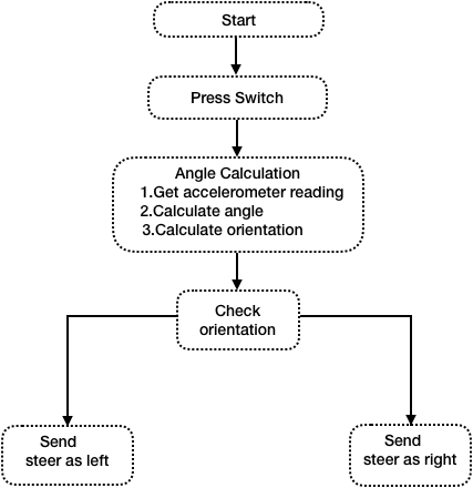
Following is the software flowchart followed for player module
Nordic Wireless
We have used Nordic Wireless communication to send the ready status and orientation of player1 and player2 to Master. The mesh network drivers were used to interface with the Nordic IC. The Nordic nRF24L01+ is a highly integrated, ultra low power 2Mbps RF transceiver IC for the 2.4GHz ISM (Industrial, Scientific and Medical) band. The Nordic nRF24L01+ integrates a complete 2.4GHz RF transceiver, RF synthesizer, and baseband logic. We had to attach a RP-SMA Connector antenna to communicate between the multiple nodes. Nordic wireless can be used in multiple applications such as smart homes, games, consumer electronics and PC peripherals. We made use of Preet’s Low Powered Mesh Network stack.
Each packet is sent via an existing route, and if route has changed, a new route is automatically discovered using a special retry packet. Each node's ACK contains some meta-data about the node itself. This data includes information about its routing table, and other statistic. Duplicate packets are absorbed but an ACK is still replied if it's a duplicate, but a retry packet. An ACK packet or a response to an ACK all use retries; even the repeating nodes participate to make sure the packet is delivered. The minimum payload is 9 bytes, of which, 8 bytes will be the mesh header overhead. The higher the payload, the higher the efficiency of the network. The eight bytes of payload header contains the network source and destination information, along with packet type and hop count information.
For example, if the payload size is 32 bytes, then 8 bytes are used by the network header and 24 bytes are free to be used for transmitting the data.
The mesh_packet_t is a structure that is used to transmit the data to understand the data of the wireless packet. It has 4 struct variables.
nwk : Packet network address
mac : packet physical address
info:Packet header
Data:uint8_t type of data that is sent..
In this example, both the player boards send the ready status and orientation to master. After getting ready status from both the players game will start and then master start receiving the orientation.Furthermore, we show you how data variables can be exchanged between two boards. A wireless Tx task was created which was used to handle the wireless Nordic transmissions.
Hardware Design
The Nordic wireless is connected over SPI lines on SJone board
Software Design
Here are some of the Nordic wireless API we used for our project.
1. This function is responsible to send the packet wherein the address of the destination node, type of mesh protocol used, pointer to the data to send, length of the data to send and number of hops is passed as a parameter. It returns true if packet is sent successfully.
wireless_send(Master_Rx_Address, mesh_pkt_nack, &steer, sizeof(steer), 0)
2. This function is periodically called to get a queued packet. It takes variable of type mesh_packet_t to store the received packet and queue wait time. It returns true if a packet is dequeued or false if there is no packet.
wireless_get_rx_pkt(&rcvPkt, timeout_ms)
RGB LED Display Matrix Module
For the User Interface, a 64x64 LED Display Matrix has been used in this project. It has 5 address lines an
Other specifications of 64x64 RGB LED Matrix are as follows:
- Brightness: 2800cd/square meter
- Size: 160x160mm
- Pitch: 2.5M
- 5 Addressable Pins
- Scan: 1/32
- Refresh Frequency: >=400HZ
- Waterproof Class: IP43
- Weight: 204.8g (only matrix panel).
Hardware Design
SJOne board GPIO pins output 3.3V. However, to drive the RGB LED Display Matrix we need 5V. So, 3.3V from the SJOne Board is converted to 5V using 2 level shifters as shown in the pin connection diagram below:
LED Matrix Control
Hardware Interface
The RGB LED Display Matrix gets the input from Master Module (SJOne board). It is driven by the GPIO Pins of the Master Module. However, these GPIO pins are not connected directly to the display matrix since 64x64 RGB LED Matrix drives on 5V input whereas the GPIO pins from SJOne board output 3.3V. So, two level shifter ICs are used as an intermediate connection to convert 3.3V GPIO output from SJOne board to 5V before giving it as an input to the RGB Led Matrix.
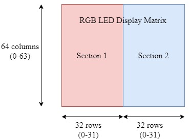
This 64x64 LED matrix has 5 address lines viz. A, B, C, D, E. With 5 address lines, we get 2^5 = 32 unique addresses. But, the matrix has 64 rows. The scan rate of the LED Matrix is 1/32, i.e., 2/64. This indicates that by making each address line high, two rows will be driven at the same time.
The LED display Matrix is divided into two sections-
- Section 1 - First 32 rows (Row 0 to row 31)
- Section 2 - Remaining 32 rows (Row 32 to row 63)
6 data lines, 3 for each section are available to drive the RGB matrix.
- R1, G1, B1 - For section 1
- R2, G2, B2 - For section 2
Other pins:
- OE - Output Enable
- Lat - Latch
- Clk - clock signal
- Vcc - High Voltage (5V)
- Gnd - Ground (0V)
Software Design
Entire driver function for RGB LED Matrix APIs was self-written from scratch.
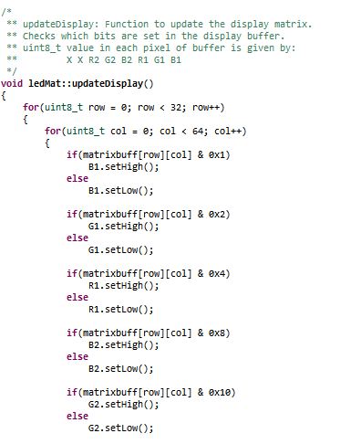
Logic: In order to save the memory, a buffer of size 32x64 used instead of using 64x64 buffer and updated every 1ms. This buffer stores the pixel values of the RGB LED matrix and updates them every 1ms. A variable of 8-bits is stored in each cell, where the first two MSB bits are not used and the remaining 6-bits represent 6 RGB data lines as: (X X R2 G2 B2 R1 G1 B1).
 uint8_t matrixbuff[MATRIX_NROWS][MATRIX_HEIGHT];                       where, MATRIX_NROWS  = 32
                                                                               MATRIX_HEIGHT = 64
                                                                               uint8_t pixel_value-> X X R2 G2 B2 R1 G1 B1
In order to drive only one row, particular address lines can be made high and enabling the RGB pins for the section in which that row lies. For example, to glow the first row (row 0) red, ABCDE = 00001 and R1 = 1. All other RGB pins should be made 0.
With the combination of address lines and 6 RGB pins, any particular row with a specific color can be displayed.
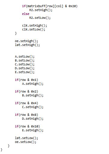
In order to update a single LED pixel value, set the variable (X X R2 G2 B2 R1 G1 B1) conditions to update the matrix buffer, and then set the clock high and low (to indicate one clock pulse). Repeat this process for as many columns present in the matrix. After this, set the output enable and latch pins high. Now, set the address lines depending upon the values set in the row number. After doing this, set the latch and output enable pins low. And then repeat this process for as many times as the number of rows (in our case, the row number is 64 but, since the matrix buffer is selected as 32 to save memory by dividing into two sections, it will be 32). In this way the pixel values are set high or low and stored in the buffer. The updateBuffer() function is called every 1ms to update the LED matrix display.
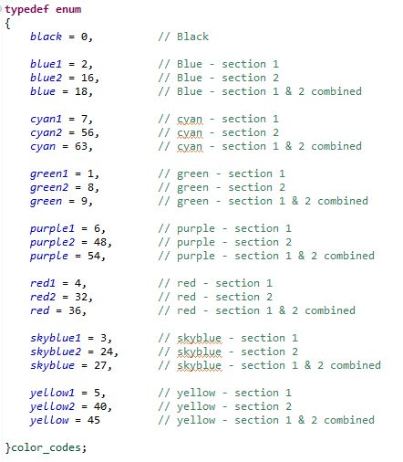
Depending upon the different values that can be stored in each cell value, an enum is used to represent different color values as shown in the below image. This helps the Master module to directly pass any color value from the enum in order to display a specific color and in a specific section of the LED Matrix Display. For example: If the Master wants to display the car for Player 1 (Player 1 is represented by red color and is in section 1) starting from position (24, 2), then it just has to call the display API function as follows:
drawCar(24, 2, red1); Note: red1 = 4 (00000100) -> R1 is set.
Similarly, if the Master wants to display the car for Player 2 (Player 2 is represented by blue color and is in section 2) at (55, 2), then it can be displayed by calling the same function
 drawCar(24, 2, red2);                       Note: red2 indicates that we want to display in Section 2.
                                                          red2 = 32 -> (00100000) -> R2 is set.
                                                          x = 55 in the display corresponds to x=24 for section 2.
To display red cars at the specified location on both the sections at the same time,
drawCar(24, 2, red); Note: red = 36 (00100100) -> R1 & R2 are set.
Also, each pixel values can be updated using drawPixel() or clearPixel() functions.
Functions like moving the display down to get real-time game feel (making sure that score displayed on the top remains intact) was a challenging task but, not impossible. It was carried out by updating the matrix updating the pixel value by copying the value above it and doing this for each pixel in a column and subsequently for all the rows to cover the entire matrix.
matrixbuff[x][y] = matrixbuff[x][y+1];
The play area above 53rd column (col=52) was uncahnged as it was reserved to display the scores. The topmost pixel value to be moved down in this application was the 53rd pixel in each row. It was cleared and all other pixel values below it were moved down. However, challenging part was to generate dotted lane marking lines at every interval while moving the display down. In the rows corresponding to these lane markings (x=10 and x=21), pixels were cleared for count equal to 4 and 5 and they were set otherwise and count made to zero after count = 5. Thus, this gave us dotted lane lines (2 pixels cleared after every 3 pixels set) at rows 11 and 22 while moving the display down.
Implementation
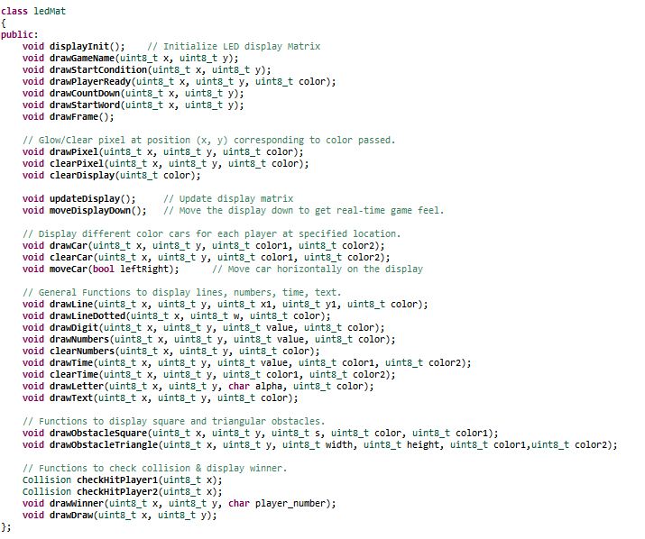
Various functions were written to display pixels, lines (dotted or solid), digits, numbers, time, text, cars, obstacles as well as to clear them. Also, APIs to check if the player hit the obstacle or no and to display the starting condition and winner of the game were written. These APIs are called by the Master module to carry out specific tasks and check conditions depending upon the values obtained from the player module. Below diagram shows the functions in the display matrix API
Master Module
The master module takes care of implementing the algorithm of game and driving the RGB LED matrix
Hardware Design
The master module takes orientation input from two players through Nordic wireless. After taking the inputs from the wireless sensor the master module implements the algorithm to drive the simulated car on RGB LED matrix. The algorithm checks for the collision of car with the obstacles. If the car collides with square obstacles then the score gets incremented and if it collides with triangular obstacle then the score is decremented. It checked for timer and as 60 seconds get over it decide the winner based on the score and display the winner
Hardware Interface
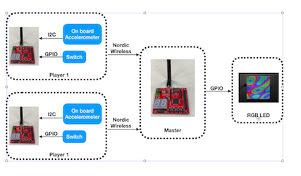
The following diagram represents the hardware interface and hardware protocol used for the communication.
Software Design
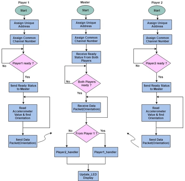
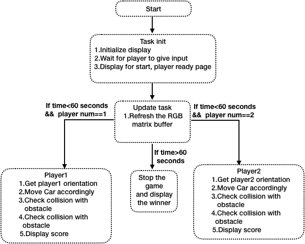
The Master application file consists of 5 tasks Init, Display update, layout design obstacle generation, Player1 task and Player2 task. As soon as the application starts, the Init task does the Gpio configuration of the RGB led matrix, put the initial graphics on the matrix and would wait for Player to send the start signal. Once the players send the start signal then the other task layout, obstacle, and players task start to run.Player1 and player2 task takes care of car movement for triangular obstacle avoidance and hitting the square obstacle.The obstacle generates obstacle for all the three paths for player.The obstacle voidance and display update task has higher priority than the player task.
Implementation
FreeRtos API was used were used for the implementation of the master module. Following approach were followed for the implementation
1. The function with the same functionality and had the same code for example both the players were kept in two different task of equal priority
2. The update Display task which refreshes the buffer of LED Matrix was kept at the higher priority than the player task with vTaskdelay of 1 ms.
3. The obstacle generation task was kept at the same priority as of update display task.
4. The start display pages to show that both the players are ready were kept in one task and the task was suspended once the game starts to save CPU cycles
PCB Design
The Printed Circuit Board design was done using Dip Trace open-source software. The software design tool provides drag and drop functionalities using which we created our own design. The connections are divided between top and bottom layers to ensure that the design rule conditions are not violated.
Testing & Technical Challenges
Issues and Challenges
1. No Datasheet
There is no datasheet available for the 64x64 RGB Led Display Matrix. So, we had to read the other LED matrix module datasheets and analyze the data and addressing scheme for our matrix module.
2. Designing the RGB LED Matrix Display driver
Writing the driver function on our own was a challenge. We were able to easily glow a single row in the matrix. However, the challenge lied in glowing a single pixel value at a specified location. And lack of datasheet made it even more difficult. Once we got the control over glowing a single LED (check updateDisplay function as shown above), we were able to implement various functions to draw lines, squares, triangles, car, digits, text.
3. Matrix flickering Issue
The application has a task to call updateDisplay() function to update the buffer every 1ms. This task had a lower priority as compared to the player transaction task in the Master module. As a result of this, the LED Display Matrix was being updated at a slower rate, and thus, leading to matrix flickering. The issue was resolved by changing the priority of the updateDisplay matrix task higher than the Player task.
4. Wireless Packet drop
The Player module was waiting for acknowledgment from the master module which delayed the sending of the orientation data. Since, the player must keep on continuously send the orientation data irrespective of the acknowledgment received from the Master board, the logic to wait for acknowledgment was removed and packet drop reduced significantly. This led to the smooth movement of the car on the display as Master started receiving continuous data from the Player module.
5. Wireless noise interference
We tried different channels from 2400-2499 and picked the channel number 2499 as it was giving the least noise interference in the communication between our Player boards and the Master board.
Testing
1. Calling display API functions in tasks as opposed to calling in main
Various functions were written in Display Matrix module and tested. This functions can be directly called in main and checked on the display. However, to avoid issues during integration with the master, which ran multiple tasks by checking the logic, the display matrix functions were called by running multiple tasks in Display Matrix module and tested there itself. After which they were integrated with Master module. So, if multiple tasks calling these functions had issues, then it could be resolved right away before integrating with the Master module.
1. Feature by Feature testing
We tested the application as soon as we completed one feature. As soon as a function was written bY Display Matrix members, it was tested on the display. Further, it was integrated with the Master module tasks and tested. This helped a lot in debugging the issues while integrating.
Conclusion
We were able to successfully design a 2-player car racing game using RGB LED Matrix. This project helped us gain a working knowledge of FreeRTOS tasks and how to write drivers. Along the course of the project, we faced many hardware and software issues, especially while integrating a new module into the existing working solution. But, in spite of all the difficulties, we were able to achieve our goal with the help of proper understanding and teamwork. Working in a group and managing schedules, it felt as if we were doing an internship. Overall, it was a great learning experience which molded us into better than what we were before we started.
- Team Work: Working in a team with different people gave us the industry experience. There were quite a lot of time when we did not agree which lead to discussions and logical reasoning to come to a consensus decision.
- GIT: Our source code versioning, code review sessions and test management were done using GIT.
- Debugging: We followed the debugging technique discussed by Preet in the class. When we have multiple tasks and have to figure out which task is the culprit, we must comment the task which is working fine, making sure it still fails. And keep doing this until the culprit task is found out. This helped a lot in debugging the master module as it had lots of tasks implemented.
Project Video
Game Video - Death Race
Project Source Code
Git - Death Race by Magnum Opus
References
Acknowledgement
We would like to thank our professor, Preetpal Kang for designing such a course where learning was his guidance and consistent feedback. We would also like to thank the ISA team for their valuable inputs, support and motivation whenever needed. Finally, the credit goes to our entire team, Magnumopus. With full support and cooperation from each other, we were successfully able to complete this project as planned. It was a matter of hardships and sleepless nights but, the amount of knowledge and experience gained was worth the struggle. In the end, the praise from the professor and other peers after the presentation were inspiring and we look forward to further optimize the project and add more features.
References Used
[1] Adafruit 64x64 RGB LED Matrix
[3] Everything You Didn't Want to Know About RGB Matrix Panels
[4] Marutsu - RGB Pin Configuration
[6] LED Text Image
[7] Nordic Datasheet
[8] FreeRTOS
