Difference between revisions of "S18: Rahee"
Proj user6 (talk | contribs) (→Software Design) |
Proj user6 (talk | contribs) (→Appendix) |
||
| (231 intermediate revisions by the same user not shown) | |||
| Line 1: | Line 1: | ||
| − | |||
| − | |||
| − | |||
| − | |||
| − | |||
| − | |||
| − | |||
| − | |||
| − | |||
| − | |||
| − | |||
| − | |||
== Rahee == | == Rahee == | ||
| + | {| | ||
| + | |[[File:Rahee_Image.jpg|400px|left|thumb|Rahee Front View]] | ||
| + | | | ||
| + | | | ||
| + | |[[File:Rahee_Image2.jpg|400px|left|thumb|Rahee Back View]] | ||
| + | | | ||
| + | |} | ||
== Abstract == | == Abstract == | ||
| − | Bikes are being widely adopted as | + | Bikes are being widely adopted as either a leisure sport or as a mode of transportation. In |
2015, in USA alone 14.5 million bikes were sold. The world is following as well. Even with | 2015, in USA alone 14.5 million bikes were sold. The world is following as well. Even with | ||
such a high number of users, there has been a dearth of smart accessories for bikes to enhance | such a high number of users, there has been a dearth of smart accessories for bikes to enhance | ||
| Line 21: | Line 16: | ||
accessory addresses these issues. To make a bike smarter and to address the issues which | accessory addresses these issues. To make a bike smarter and to address the issues which | ||
have so far been omnipresent in the bike industry, we propose Rahee- a solution towards | have so far been omnipresent in the bike industry, we propose Rahee- a solution towards | ||
| − | making bike riding safe and bikes secure. | + | making bike-riding safe and bikes secure. |
The smartness of this device lies in its ability to connect to your phone via Bluetooth. This | The smartness of this device lies in its ability to connect to your phone via Bluetooth. This | ||
battery-operated device can be mounted on the handlebar of any bike. It will be capable of | battery-operated device can be mounted on the handlebar of any bike. It will be capable of | ||
| − | doing | + | doing three different things that will help make the bike smart – navigation, smart headlight and an anti-theft alarm. |
The most important feature of this device is the navigation and its anti-theft capability | The most important feature of this device is the navigation and its anti-theft capability | ||
(which actually works). It will also connect with the Google Maps on the smartphone and | (which actually works). It will also connect with the Google Maps on the smartphone and | ||
| Line 30: | Line 25: | ||
== Objectives & Introduction == | == Objectives & Introduction == | ||
| − | Rahee aims at enhancing the overall experience of using a bike. | + | |
| + | ''' Introduction ''' | ||
| + | |||
| + | Rahee aims at enhancing the overall experience of using a bike. Rahee aims to replace a conventional navigation accessory, by adding accessible navigation feature using leds and provide features such as anti-theft alarm and automated headlight. The aim of this project is to integrate these features using FreeRtos API on a ARM-M3 powered SOC: LPC1758. | ||
| + | |||
| + | ''' Objectives ''' | ||
The main objectives of this project are as follows: | The main objectives of this project are as follows: | ||
| − | * | + | * To embed navigation in Leds using neoPixel Ring LEDs |
| − | * | + | * To develop an algorithm for the Anti-Theft and Alarm feature |
| − | * | + | * To Drive the DF Player on Detection of a malicious motion using the UART protocol |
| − | + | * To integrate all the different attributes to work together as a single device | |
| − | + | * To develop an user-friendly Android application | |
| + | * To configure Bluetooth module as a communication bridge between the Android Application and the SJONE board | ||
| + | * To integrate all the tasks above and synchronize them using FreeRTOS API | ||
| + | |||
| + | == Team Members & Responsibilities == | ||
* Tanmay Shinde | * Tanmay Shinde | ||
** Automatic Headlamp Driver | ** Automatic Headlamp Driver | ||
** PCB Designing | ** PCB Designing | ||
* Ankith Shetty | * Ankith Shetty | ||
| − | ** LED Indicator Display Driver | + | ** Neo-Pixel RGB LED Indicator Display Driver |
* Siddharth Chawla | * Siddharth Chawla | ||
** Android App | ** Android App | ||
** PCB Designing | ** PCB Designing | ||
* Akshay Ghodke | * Akshay Ghodke | ||
| − | ** Driver and circuit for | + | ** Driver and circuit designing for alarm |
** Anti theft feature | ** Anti theft feature | ||
* Ashish Lele | * Ashish Lele | ||
| Line 89: | Line 93: | ||
! scope="row"| 4 | ! scope="row"| 4 | ||
| 4/24/18 | | 4/24/18 | ||
| − | | Embedding Navigation in LED | + | | Embedding Navigation in LED Ring |
| − | | The heart of the accessory lies in its navigation and driving the LED using this data. The | + | | The heart of the accessory lies in its navigation and driving the LED using this data. The LED Ring employs the use of PWM in order to drive various segments of it. For example, a right turn in the app will illuminate the right half of the LED Ring. |
| PWM posed a serious challenge when driving multiple pixels at once. This led to change our initial design philosophy from PWM to GPIO. | | PWM posed a serious challenge when driving multiple pixels at once. This led to change our initial design philosophy from PWM to GPIO. | ||
| Completed | | Completed | ||
| Line 98: | Line 102: | ||
| 4/24/18 | | 4/24/18 | ||
| Developing Anti-theft device | | Developing Anti-theft device | ||
| − | | The Anti-theft device feature makes use of | + | | The Anti-theft device feature makes use of an external accelerometer which communicates with the SJONE board using SPI protocol. It also employs the use of a mp3 decoder and a speaker. |
| − | | Calibrating the accelerometer and | + | | Calibrating the accelerometer and synchronizing the different tasks(Playing Sound) which it will trigger, yielded a small challenge. |
| Completed | | Completed | ||
| Line 107: | Line 111: | ||
| Automating the Headlamp | | Automating the Headlamp | ||
| The Headlamp uses the Light sensor which is placed in the enclosure. It will illuminate based on the lighting conditions of the environment and will have a blinking feature. | | The Headlamp uses the Light sensor which is placed in the enclosure. It will illuminate based on the lighting conditions of the environment and will have a blinking feature. | ||
| − | | The current | + | | The current dropped by a factor of 30 when PWM port was driving the headlamp. |
| Completed | | Completed | ||
| Line 123: | Line 127: | ||
| This task involved integrating all the modules together and maintain synchronization between them. | | This task involved integrating all the modules together and maintain synchronization between them. | ||
| None | | None | ||
| − | | | + | | Completed |
|- | |- | ||
! scope="row"| 9 | ! scope="row"| 9 | ||
| − | | 5/ | + | | 5/22/18 |
| Testing | | Testing | ||
| − | | | + | | The testing phase included a thorough testing of the app functionality and how the MCU behaves with it. Testing was also divided into different segments to allow better allocation. |
| − | | | + | | Due to the PCB being delayed, the connections were not reliable. |
| + | | Completed | ||
|} | |} | ||
| Line 185: | Line 190: | ||
| $0.23 | | $0.23 | ||
|- | |- | ||
| − | ! scope="row"| | + | ! scope="row"|HC05 |
| Arduino Wireless Bluetooth Module | | Arduino Wireless Bluetooth Module | ||
| Amazon | | Amazon | ||
| 1 | | 1 | ||
| $10.57 | | $10.57 | ||
| + | |- | ||
| + | ! scope="row"|1890 | ||
| + | | Mini Metal Speakers | ||
| + | | HSC, San Jose | ||
| + | | 1 | ||
| + | | $2.57 | ||
|- | |- | ||
|} | |} | ||
| Line 199: | Line 210: | ||
The hardware employs the use of multiple sensors in order to interact with its surrounding environment. The sensors are used to control the two essential feature of this accessory- automatic headlamp and anti theft device. The automatic headlamp is toggled based on the light value detected by the light sensors. An accelerometer is used to implement the anti-theft feature by detecting sudden motion which enables us to trigger the alarm. The device communicates with the Mobile Application using Bluetooth. | The hardware employs the use of multiple sensors in order to interact with its surrounding environment. The sensors are used to control the two essential feature of this accessory- automatic headlamp and anti theft device. The automatic headlamp is toggled based on the light value detected by the light sensors. An accelerometer is used to implement the anti-theft feature by detecting sudden motion which enables us to trigger the alarm. The device communicates with the Mobile Application using Bluetooth. | ||
| − | [[File: | + | [[File:RaheeHardwareDesign1.png|center|700px|thumb|Hardware Design]] |
| − | ==== | + | |
| + | ==== DFPlayer Mini MP3 Player Module ==== | ||
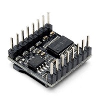
The DFPlayer Mini is a MP3 module with a simplified output, which can be directly connected to a speaker. This module can be used as a stand alone module with attached battery, speaker and push buttons or also can be used with any Micro-controller with RX/TX capabilities. A variety of control modes, I/O control mode, serial mode, AD button control mode can be interfaced with DFP player MP3 decoder. | The DFPlayer Mini is a MP3 module with a simplified output, which can be directly connected to a speaker. This module can be used as a stand alone module with attached battery, speaker and push buttons or also can be used with any Micro-controller with RX/TX capabilities. A variety of control modes, I/O control mode, serial mode, AD button control mode can be interfaced with DFP player MP3 decoder. | ||
| Line 220: | Line 232: | ||
{| | {| | ||
|[[File:LightSensor.jpg|200px|left|thumb|ALS-PT19 Light Sensor]] | |[[File:LightSensor.jpg|200px|left|thumb|ALS-PT19 Light Sensor]] | ||
| − | |||
|} | |} | ||
==== ADXL362 Triple Axis Accelerometer Breakout ==== | ==== ADXL362 Triple Axis Accelerometer Breakout ==== | ||
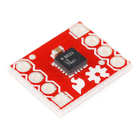
| − | It is a complete 3-axis MEMS acceleration measurement system with low power consumption. | + | It is a complete 3-axis MEMS acceleration measurement system with low power consumption. Among the many features it offers, one of the core feature which was used - was to measure dynamic shock resulting from shock. It communicates over SPI and built-in logic generates an interrupt if shock is detected at a certain sensitivity |
{| | {| | ||
|[[File:RaheeAccelerometer.jpg|200px|left|thumb|ADXL362 Accelerometer]] | |[[File:RaheeAccelerometer.jpg|200px|left|thumb|ADXL362 Accelerometer]] | ||
| − | | | + | |} |
| + | |||
| + | ==== HC05 Wireless Bluetooth Module==== | ||
| + | |||
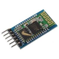
| + | The HC-05 Bluetooth Module is an easy Bluetooth SPP (Serial Port Protocol) module, designed for transparent wireless serial connection setup. It serves as a full-duplex communication bridge between an Android application and the SJONE board. It uses simple UART communication protocol which makes it easy to interface with different controllers. | ||
| + | |||
| + | {| | ||
| + | |[[File:Bluetooth.jpg|200px|left|thumb|HC05 Wireless Bluetooth]] | ||
|} | |} | ||
| Line 245: | Line 263: | ||
=== Hardware Interface === | === Hardware Interface === | ||
| − | + | ||
| + | The sensors are communicating with the Master controller using their designated BUSes. The Bus map is as follows- | ||
| + | |||
| + | 1.The accelerometer is communicating with the master controller using the SPI bus. | ||
| + | |||
| + | {| | ||
| + | |[[File:ACC.png|400px|left|thumb|SPI bus and accelerometer communication]] | ||
| + | |} | ||
| + | |||
| + | 2.The Bluetooth and the DFPlayer is using the UART bus to communicate with the microcontroller and the peer device. | ||
| + | |||
| + | {| | ||
| + | |[[File:UARTImplementation.png|400px|left|thumb|UART bus communicating with Bluetooth and DFPlayer]] | ||
| + | |} | ||
| + | |||
| + | 3. The light sensor uses an analog pin to record raw values, which are converted to digital values using ADC. | ||
| + | |||
| + | {| | ||
| + | |[[File:ADC1.png|500px|left|thumb|ADC and Light sensor Interaction]] | ||
| + | |} | ||
| + | |||
| + | 4. The PCB layout is displayed in the image below. | ||
| + | |||
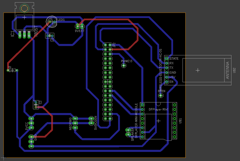
| + | [[File:Board1.png|800px|center|thumb|PCB Layout .brd ]] | ||
| + | |||
| + | 5. Overview of hardware interface | ||
| + | |||
| + | [[File:Detailed Hardware Interface.png|800px|center|thumb|Detailed Hardware Interface]] | ||
=== Software Design === | === Software Design === | ||
| − | + | Since the software for the accessory is distributed around the application and the Microcontroller. This requires for the software design of the project to be divided into into segments | |
| − | a. MCU firmware design | + | a. ''MCU firmware design'' |
| − | b. Android | + | b. ''Android Application design'' |
| − | Since, the firmware is | + | Since, the firmware is an essential part of this project, it will be discussed first. |
| − | + | ==== MCU firmware design ==== | |
| − | + | The StateMachine below captures the flow of the tasks. | |
| − | The | ||
| − | |||
| − | |||
| − | + | {| | |
| − | This task controls the headlight. It polls the two light sensors in order to get an accurate value and drive the headlamp. The light sensors are sampled on an analog pin and using ADC, these raw values are being converted into meaningful data. | + | | |
| − | Pseudo Code | + | |[[File:Software_State_Machine_Final.jpg|500px|thumb|left|Software State Machine]] |
| − | a. | + | | |
| + | |[[File:Legends_Final0.jpg|500px|thumb|center|Legends]] | ||
| + | | | ||
| + | |} | ||
| + | |||
| + | |||
| + | ''' 1. DirectionTask ''' | ||
| + | |||
| + | The directionTask is the highest priority task and which starts executing as soon as the peer device is connected with the MCU. The state machine shown above captures this transition perfectly.The Direction Task drives the neopixel using the navigation data from the Rahee Android App. Priority->Highest. This priority is justified by the need of nanoseconds accuracy of the delay needed to drive the NeoPixel ring. | ||
| + | |||
| + | ''' Pseudo Code ''' | ||
| + | a. Bluetooth module state pin is continuously monitored in this task and set to bike_lock variable | ||
| + | b. Direction task will only run in case the Bluetooth module is connected | ||
| + | c. If the bike_lock = 1, directionTask is executed as follows: | ||
| + | i. Suspends Anti-theft and Alert Task | ||
| + | ii. Resume toggleHeadlightTask | ||
| + | iii. Direction variable continuously receives the signal from an Android App in toggleHeadlightTask | ||
| + | vi. This Direction variable is used in a switch case to identify which direction to be displayed on the NeoPixel ring | ||
| + | d. If the bike_lock = 0: | ||
| + | i. Resumes Anti-theft and Alert Task | ||
| + | ii. DirectionTask skips and is suspended along with the toggleHeadlightTask. | ||
| + | |||
| + | // NOTE: The Direction variable is monitored in toggleHeadlightTask on purpose since this being a critical task! | ||
| + | |||
| + | ''' Flowchart ''' | ||
| + | |||
| + | [[File:DirectionTask_Algo_Final1.jpg|500px|thumb|center|Direction Task Algorithm]] | ||
| + | |||
| + | |||
| + | ''' 2. Toggle Headlight''' | ||
| + | |||
| + | This task controls the headlight. It polls the two light sensors in order to get an accurate value and drive the headlamp. The light sensors are sampled on an analog pin and using ADC, these raw values are being converted into meaningful data. Priority -> Medium. | ||
| + | |||
| + | ''' Pseudo Code ''' | ||
| + | a. This Task monitors the Direction values from the Android App and the light sensor values continuously | ||
| + | b. Depending upon the values on ADC( ambient brightness ), the headlight would toggle | ||
| + | c. If lightValue < 50: | ||
| + | i. the headlight turns ON | ||
| + | d. Else | ||
| + | i. the headlight remains OFF | ||
| + | |||
| + | ''' Flowchart ''' | ||
| + | |||
| + | [[File:ToggleHeadLamp_Algo_Final1.jpg|500px|thumb|center|Toggle Headlamp Task Algorithm]] | ||
| + | |||
| − | + | ''' 3. Antitheft''' | |
| + | |||
The Antitheft device can be broken down in two tasks, one which monitors the accelerometer values and then the other which plays an alert sound. The latter task comes into the picture, only if there is a jerk on the bicycle. The sensitivity of the accelerometer can be calibrated and can detect range on motions. | The Antitheft device can be broken down in two tasks, one which monitors the accelerometer values and then the other which plays an alert sound. The latter task comes into the picture, only if there is a jerk on the bicycle. The sensitivity of the accelerometer can be calibrated and can detect range on motions. | ||
| − | |||
| − | |||
| − | + | ''' Pseudo Code ''' | |
| − | This task | + | a. Continuously checks the sate pin for connection |
| − | Pseudo Code | + | b. If connected, i.e bike_lock = 1: |
| − | a. | + | i. The directionTask is resumed |
| + | c. If not connected, i.e bike_lock = 0: | ||
| + | i. Initial ADXL362 accelerometer 3-axis values are stored as a reference in the X, Y, Z variables | ||
| + | ii. This task monitors the current accelerometer values continuously | ||
| + | iii. Relative difference is calculated to identify a jerk on the bike when it is locked. | ||
| + | iv. If the jerk is beyond the set threshold: | ||
| + | 1. new reference values are set | ||
| + | 2. QueueSend sends a data to the alert task: | ||
| + | v. If the jerk is tolerable | ||
| + | 1. Continues to monitor | ||
| + | |||
| + | ''' Flowchart ''' | ||
| + | |||
| + | [[File:AntiTheft_Algo_Final.jpg|500px|thumb|center|Anti-Theft Task Algorithm]] | ||
| + | |||
| + | |||
| + | ''' 4. Alert Task''' | ||
| + | |||
| + | This task wakes on a QueueSend from the AntiTheft device and using the DFplayer plays the alert sound. The DF player drives the UART bus which is connected to the speaker input. | ||
| + | |||
| + | ''' Pseudo Code ''' | ||
| + | a. Alert task sleeps on the QueueReceive for portMAXDELAY | ||
| + | b. If the antiTheft task sends the data in the Queue | ||
| + | i. Alert is generated and speakers produce a theft alarm | ||
| + | c. If there is no data given by the Antitheft task | ||
| + | i. Continues to sleep on QueueReceive | ||
| − | '''Android App | + | ''' Flowchart ''' |
| + | |||
| + | [[File:AlertTask_Algo_Final.jpg|500px|thumb|center|Alert Task Algorithm]] | ||
| + | |||
| + | ==== Android Application design ==== | ||
| + | |||
| + | The Android App provides a simple interface for the user to communicate with the controller. | ||
| + | It consists of two activities - Main Activity and Google Maps Activity | ||
| + | The Main Activity enables users to Connect/Disconnect with Rahee by tapping on the Connect/Disconnect button. As soon as the app connects to the device, Google Maps Activity is launched. The user can then input the destination and get directions to there from the current location. | ||
| + | |||
| + | The activities are described in detail below: | ||
| + | |||
| + | ''' 1. Main Activity ''' | ||
| + | |||
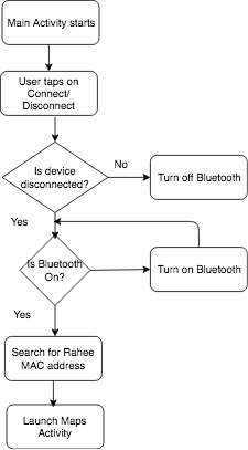
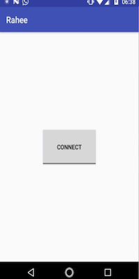
| + | The Main Activity allows users to Connect/ Disconnect with the device through Bluetooth. Once the user taps on the Connect button, it confirms if the Bluetooth was turned on and searches for the MAC address of Rahee in the list of active paired devices. Once the MAC address is found, it automatically launches the Google Maps Activity using an Intent. While launching the Google Maps Activity it also passes the BluetoothDevice object to enable communication in the other activity. | ||
| + | |||
| + | {| | ||
| + | |[[File:AndroidMain.png|left|300px|thumb|Android Application Main Activity Flow Diagram]] | ||
| + | | | ||
| + | | | ||
| + | |[[File:AndroidMainSS.png|center|200px|thumb|Android Application Main Activity]] | ||
| + | | | ||
| + | |} | ||
| + | |||
| + | |||
| + | |||
| + | ''' 2. Google Maps Activity''' | ||
| + | |||
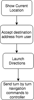
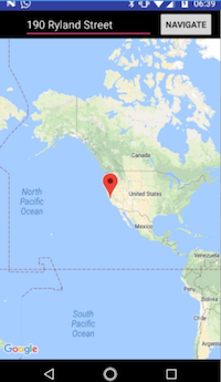
| + | The Google Maps Activity initially displays the current location of the user. It allows the user to enter a destination address to navigate to by entering it in the Text View widget at the top of the screen. Once the destination address is entered the user can tap on the Navigate button to launch Google Maps Directions. The Google Maps Directions are configured to operate in Bike Mode and avoid Highways keeping in mind the convenience and safety. The directions also send turn by turn navigation commands over Bluetooth which is used to display directions on the LED ring on the device. | ||
| + | |||
| + | {| | ||
| + | |[[File:AndroidMaps.png|200px|left|thumb|Google Maps Activity Flow Diagram]] | ||
| + | | | ||
| + | | | ||
| + | |[[File:AndroidMapsSS.png|200px|center|thumb|Google Maps Activity]] | ||
| + | | | ||
| + | | | ||
| + | |[[File:AndroidNavigationSS.png|200px|right|thumb|Navigation]] | ||
| + | | | ||
| + | |} | ||
=== Implementation === | === Implementation === | ||
| − | + | ||
| + | '''Driving NeoPixel Ring''' | ||
| + | |||
| + | The Neopixel rings comes up with strict guidlines on its timing. Its hence highly critical to understand its timing diagram in order to enable transmission.The below figure shows the timing constraints of the neopixel. | ||
| + | |||
| + | {| | ||
| + | |[[File:Neopixel_Led_Working.PNG|500px|left|thumb|Timing Constraints]] | ||
| + | | | ||
| + | |} | ||
| + | |||
| + | The pseudo code below tries to captures these constraints . | ||
| + | a.Give Reset for more than 50us. Send 24 bits with reset according to the timing chart in between. | ||
| + | b.For high, it should remain high for 600 ns | ||
| + | c.For low, it should remain low for 300ns | ||
| + | |||
| + | '''Accelerometer Synchronization''' | ||
| + | |||
| + | The Accelerometer is interfaced on an SPI bus. To communicate with the accelerometer, following opcodes were sent in order to do the following operations- | ||
| + | a. 0x2D to power up the sensor. | ||
| + | b. 0x0E, X0F to read the X axis of the sensor | ||
| + | c. 0x11, 0x12 to read the Y axis of the sensor | ||
| + | d. 0x13,0x14 to read the Z axis of the sensor | ||
| + | |||
| + | '''BlueTooth Communication''' | ||
| + | The bluetooth communication is being done by using the UART bus. Initially the Bluetooth's baud rate and name of the device was changed. This was done by the manufacturer bluetooth's application on the play store. | ||
| + | a. To change the name of the device, send the command AT+NAME= "<your device name>" | ||
| + | b. To change the baudRate of the device, send the command AT+Baud= <"Desired Baud Rate"> | ||
| + | |||
| + | '''Light Sensor''' | ||
| + | |||
| + | The light sensor was interfaced on an analog pin. The raw readings are then converted to digital value using ADC. Steps required to set up are- | ||
| + | a. Connect the output pin of the sensor to an ADC capable pin. | ||
| + | b. Convert the raw values to digital value using ADC. | ||
| + | |||
| + | '''Software and Hardware Implementation''' | ||
| + | |||
| + | The firmware of the device uses FreeRtos to manage between different tasks. The hardware organization and the data flow between the tasks are shown as below- | ||
| + | |||
| + | [[File:Hardware_implem-1207_1.jpg|750px|center|thumb|FirmwareDesign]] | ||
| + | |||
| + | In summary of the firmware design, the process starts from the bluetooth connection. If the device is connected, then the high priority task(Direction Task) Starts. While the direction task runs, all other tasks which are of low priority, wont run. As soon as the direction or the navigation ends, a task of lower priority runs- Anti Theft task starts running. A medium priority task sleeps on a queue which wakes on QueueSend from low priority task. The low priority tasks check for a motion on a bike and sends alert in queue which wakes the medium priority task. The medium priority tasks plays the sound. | ||
== Testing & Technical Challenges == | == Testing & Technical Challenges == | ||
| − | |||
| − | |||
| − | + | 1. PWM to drive the Neopixel LED | |
| − | === | + | The initial design philosophy to drive the neoPixel was using PWM. However, due to the stringent timing constraints of the neopixel and the cascading effect, the PWM design was replaced with a GPIO. |
| − | + | ||
| + | ''Advise''- understanding the PWM interrupts and using to drive the LED could have worked. It would be a good place to explore for driving the Neopixel Ring. | ||
| + | |||
| + | 2. GPIO current drop | ||
| + | |||
| + | The Headlamp Led, when connected with the VCC drew 300mA, however this dropped by a factor of 30 when it was being driven by the GPIO. | ||
| + | WorkAround- to add a gain, we used a BJT as a current amplifier. | ||
| + | |||
| + | ''Advise''- the circuit is basic in nature and could be evolved to do more heavy lifting. | ||
| + | |||
| + | 3. BLE to Bluetooth | ||
| + | |||
| + | Though BLE is almost as same as Bluetooth in functionality,but BLE can offer a considerable reduction in the power consumption. The module nrf8100 has the best documentation till date, but offers no library for the ARM-m3 series(We were not able to find one). The major challenge came when even after many attempts, the common handshake was erroneous. So instead of spending our effort to get it working, we switched to Bluetooth which is really simple to use. | ||
| + | |||
| + | ''Advise''- to use nrf8100, the endianness is different from the LPC's SSP controller. This is a good start to figure out before working on the handshake. | ||
| + | |||
| + | 4. Activity feature of accelerometer | ||
| + | |||
| + | The accelerometer ADXL362 has an in-built feature to detect the suspicious activity of the bike. ADXL362 has an interrupt pin on which these activity and other features like free fall can be configured. We tried using this feature by configuring the activity on external interrupt pin of the sensor but we got constant '0' value at the output. Currently we have implemented an algorithm to identify the motion or jerk detection, by setting a threshold, on the bike. | ||
| + | |||
| + | ''Advise''- The activity detection algorithm is basic in nature and can be improved by using the in-built feature after perusing the datasheet. | ||
| + | |||
| + | === Bug/issue name === | ||
| + | 1. '''Bluetooth not disconnecting(App Issue)''' | ||
| + | |||
| + | The application has a bug, where the bluetooth will not disconnect . | ||
| + | |||
| + | 2. '''Error in pausing Alert Audio''' | ||
| + | |||
| + | The alert audio, doesnt pause. A power reset is needed for the same. | ||
== Conclusion == | == Conclusion == | ||
| − | |||
| + | This project helped us learn the FreeRTOS APIs and we all can only agree here that what a nightmare this project would be if the project was implemented on a bareMetal than RTOS. | ||
| + | Due to the various components involved in the project, it gave us a really good hands on experience in understanding the functionality of different sensors and how to use different protocols. There were some challenges which we were presented with that taught us how something as trivial as a LED can put our skills to test. | ||
| + | Last, but not the least, this project helped us understand the project life-cycle and importance of good documentation. | ||
| + | |||
| + | == Future Improvements == | ||
| + | |||
| + | ''' 1. Compact Enclosure: ''' | ||
| + | Compact enclosure with a rigid support to fix the module on the bike's handle. Inclusion of PCB to avoid lose connection and increase compactness. | ||
| + | |||
| + | ''' 2. Headlight Brightness: ''' | ||
| + | Brightness can be controlled depending upon the ambient light sensed by the Light sensor | ||
| + | |||
| + | ''' 3. Fitness Activity:''' | ||
| + | Can be configured to monitor and display the following: | ||
| + | a. Heart-rate | ||
| + | b. Calories Burnt | ||
| + | c. Distance Travelled | ||
| + | d. Speed | ||
| + | |||
| + | ''' 4. Voice commands: ''' | ||
| + | Voice commands to enable the user to navigate regardless of the display ring | ||
| + | |||
| + | ''' 5. MP3 player: ''' | ||
| + | DFplayer mini module can be configured to design a mp3 player enabling the user to listen to their favorite songs | ||
| + | |||
| + | ''' 6. Power consumption: ''' | ||
| + | Bluetooth can be switched with BLE to reduce the power consumption. | ||
| + | |||
| + | == Acknowledgement == | ||
| + | We thank Professor '''Preetpal Kang''' for teaching us embedded software and giving us this opportunity to explore the world of embedded systems by ourselves. | ||
| + | We are also thank the '''CMPE-244 ISA team''' for being supportive and helpful throughout the project and the course. | ||
| + | |||
| + | == Appendix == | ||
=== Project Video === | === Project Video === | ||
| − | + | * [https://youtu.be/cWnDcmSUPUU Project Video] | |
=== Project Source Code === | === Project Source Code === | ||
| − | * [https:// | + | * [https://drive.google.com/open?id=10WrXJObmhCHV8utMJq1ZNsMEV15a-QPq Source Code link] |
== References == | == References == | ||
| − | = | + | [1] CMPE 244 Lecture notes from Preetpal Kang, Computer Engineering, San Jose State University. Jan-May 2017. |
| − | + | [2] [http://www.socialledge.com/sjsu/index.php?title=Realtime_OS_on_Embedded_Systems FreeRTOS documentations] | |
| − | + | [3] Spring 2017 and Spring 2016 Wiki reports | |
| − | + | [4] [http://www.freertos.org/a00106.html FreeRTOS API reference] | |
| − | + | [5] [https://cdn-shop.adafruit.com/datasheets/WS2812.pdf Neo Pixel LED Ring datasheet] | |
| + | [6] [https://cdn.makezine.com/uploads/2014/03/hc_hc-05-user-instructions-bluetooth.pdf HC-05 datasheet] | ||
| + | [7] [http://www.analog.com/media/en/technical-documentation/data-sheets/ADXL362.pdf ADXL362 Accelerometer datasheet] | ||
| + | [8] [http://www.everlight.com/file/ProductFile/201407061531031645.pdf ALS PT19 datasheet] | ||
Latest revision as of 10:40, 27 May 2018
Contents
- 1 Rahee
- 2 Abstract
- 3 Objectives & Introduction
- 4 Team Members & Responsibilities
- 5 Schedule
- 6 Parts List & Cost
- 7 Design & Implementation
- 8 Testing & Technical Challenges
- 9 Conclusion
- 10 Future Improvements
- 11 Acknowledgement
- 12 Appendix
- 13 References
Rahee
Abstract
Bikes are being widely adopted as either a leisure sport or as a mode of transportation. In 2015, in USA alone 14.5 million bikes were sold. The world is following as well. Even with such a high number of users, there has been a dearth of smart accessories for bikes to enhance the experience of owning them. Moreover, it will not break news if anyone reports a bike theft. The adoption of bikes as a mode of transportation is on a constant rise, but no single accessory addresses these issues. To make a bike smarter and to address the issues which have so far been omnipresent in the bike industry, we propose Rahee- a solution towards making bike-riding safe and bikes secure. The smartness of this device lies in its ability to connect to your phone via Bluetooth. This battery-operated device can be mounted on the handlebar of any bike. It will be capable of doing three different things that will help make the bike smart – navigation, smart headlight and an anti-theft alarm. The most important feature of this device is the navigation and its anti-theft capability (which actually works). It will also connect with the Google Maps on the smartphone and will receive and indicate information about how we need to reach a destination point.
Objectives & Introduction
Introduction
Rahee aims at enhancing the overall experience of using a bike. Rahee aims to replace a conventional navigation accessory, by adding accessible navigation feature using leds and provide features such as anti-theft alarm and automated headlight. The aim of this project is to integrate these features using FreeRtos API on a ARM-M3 powered SOC: LPC1758.
Objectives
The main objectives of this project are as follows:
- To embed navigation in Leds using neoPixel Ring LEDs
- To develop an algorithm for the Anti-Theft and Alarm feature
- To Drive the DF Player on Detection of a malicious motion using the UART protocol
- To integrate all the different attributes to work together as a single device
- To develop an user-friendly Android application
- To configure Bluetooth module as a communication bridge between the Android Application and the SJONE board
- To integrate all the tasks above and synchronize them using FreeRTOS API
Team Members & Responsibilities
- Tanmay Shinde
- Automatic Headlamp Driver
- PCB Designing
- Ankith Shetty
- Neo-Pixel RGB LED Indicator Display Driver
- Siddharth Chawla
- Android App
- PCB Designing
- Akshay Ghodke
- Driver and circuit designing for alarm
- Anti theft feature
- Ashish Lele
- Bluetooth Communication Bridge
- Product enclosure design
Schedule
| Week# | Date | Task | Description | Challenges | Status |
|---|---|---|---|---|---|
| 1 | 4/3/18 | Project Discussion- | Involved detailed discussion of the project. Tasks were identified, allocation was decided according to the difficulty of the task.
Components choice was defined. The key parameters in the decision were power consumption, lumens(in case of LEDs) and form factor. |
NA | Completed |
| 2 | 4/10/18 | Component List/ Ordering | Vendors were selected based on the quality of documentation and support available. | NA | Completed |
| 3 | 4/17/18 | Basic Android App | To prepare a basic layout of the app, which describes how the data will flow among different activities and also what data will be communicated to the MCU. This helped in narrowing down the scope of development and enabled the respective developers with better understanding of the design. | NA | Completed |
| 4 | 4/24/18 | Embedding Navigation in LED Ring | The heart of the accessory lies in its navigation and driving the LED using this data. The LED Ring employs the use of PWM in order to drive various segments of it. For example, a right turn in the app will illuminate the right half of the LED Ring. | PWM posed a serious challenge when driving multiple pixels at once. This led to change our initial design philosophy from PWM to GPIO. | Completed |
| 5 | 4/24/18 | Developing Anti-theft device | The Anti-theft device feature makes use of an external accelerometer which communicates with the SJONE board using SPI protocol. It also employs the use of a mp3 decoder and a speaker. | Calibrating the accelerometer and synchronizing the different tasks(Playing Sound) which it will trigger, yielded a small challenge. | Completed |
| 6 | 05/10/18 | Automating the Headlamp | The Headlamp uses the Light sensor which is placed in the enclosure. It will illuminate based on the lighting conditions of the environment and will have a blinking feature. | The current dropped by a factor of 30 when PWM port was driving the headlamp. | Completed |
| 7 | 5/1/18 | Finalize PCB Design | EAGLE software was used to draw schematic and board diagrams for every module of our project before integrating it on a single chip | Finalizing among various designs and choosing the optimum form factor was a challenge. | Design completed |
| 8 | 5/8/18 | Integration | This task involved integrating all the modules together and maintain synchronization between them. | None | Completed |
| 9 | 5/22/18 | Testing | The testing phase included a thorough testing of the app functionality and how the MCU behaves with it. Testing was also divided into different segments to allow better allocation. | Due to the PCB being delayed, the connections were not reliable. | Completed |
Parts List & Cost
| ProductID | Product | Vendor | Quantity | Cost |
|---|---|---|---|---|
| SJONE | LPC 1758 | PreetPal Kang | 1 | $80.00 |
| 07040-PW750-N | Luxeon White Rubel LEDs | LED Supply | 2 | $7.98 |
| 10048 | Carclo Lens- Plain Tight Spot LED Optic | LED Supply | 2 | $3.18 |
| B0130LMJ4K | Generic MP3 Decoder | Amazon | 1 | $8.00 |
| 2748 | Analog Light Sensor Breakout | Adafruit | 2 | $2.50 |
| 2862 | NeoPixel Ring - 24 x 5050 RGBW LEDs | Adafruit | 1 | $20.50 |
| 10732 | Carclo Lens Holder | LED SUPPLY | 5 | $0.23 |
| HC05 | Arduino Wireless Bluetooth Module | Amazon | 1 | $10.57 |
| 1890 | Mini Metal Speakers | HSC, San Jose | 1 | $2.57 |
Design & Implementation
Hardware Design
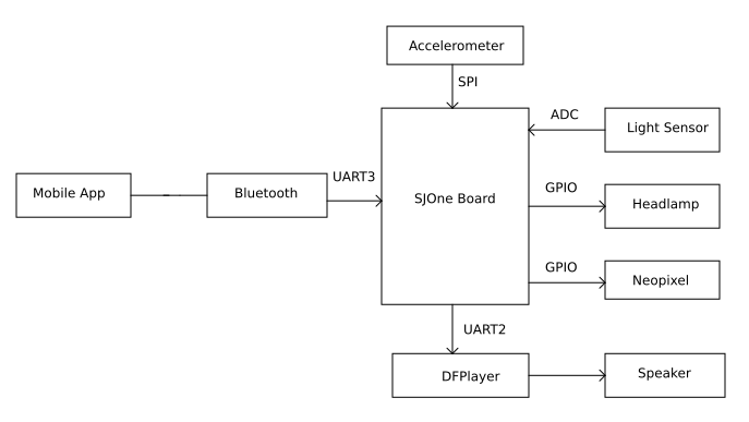
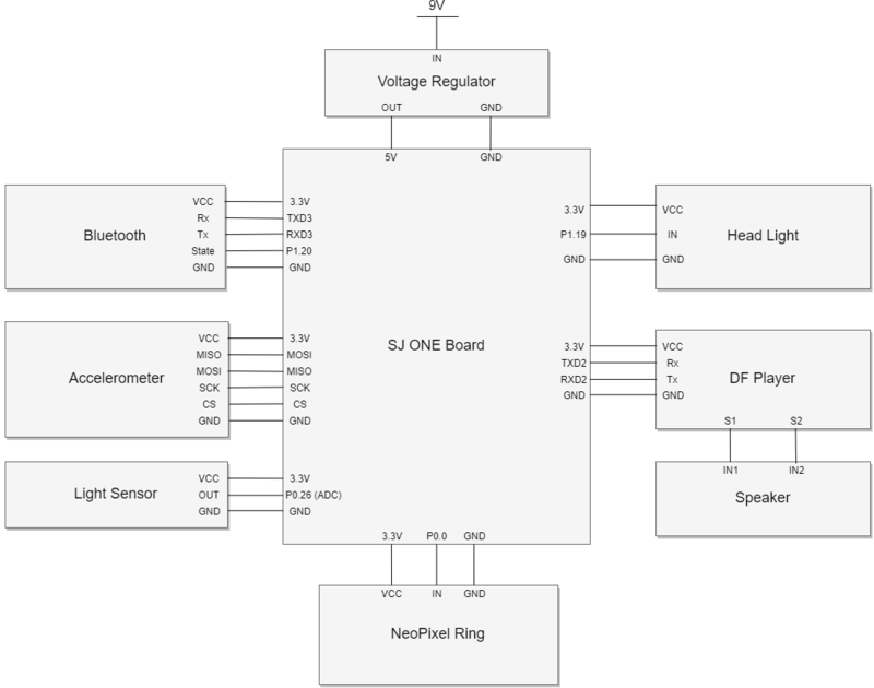
The hardware employs the use of multiple sensors in order to interact with its surrounding environment. The sensors are used to control the two essential feature of this accessory- automatic headlamp and anti theft device. The automatic headlamp is toggled based on the light value detected by the light sensors. An accelerometer is used to implement the anti-theft feature by detecting sudden motion which enables us to trigger the alarm. The device communicates with the Mobile Application using Bluetooth.
DFPlayer Mini MP3 Player Module
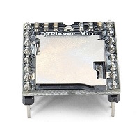
The DFPlayer Mini is a MP3 module with a simplified output, which can be directly connected to a speaker. This module can be used as a stand alone module with attached battery, speaker and push buttons or also can be used with any Micro-controller with RX/TX capabilities. A variety of control modes, I/O control mode, serial mode, AD button control mode can be interfaced with DFP player MP3 decoder.
ALS-PT19 Analog Light Sensor Breakout
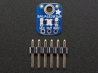
It is an analog sensor with a 2.5-5.5 V DC input signal which is proportionate to the brightness of the incoming light.This sensor contains both Infrared and full spectrum diodes. The output can be read on an analog pin of the micro-controller. This sensor is logarithmic over a large dynamic range of 3 to 55,000 Lux, so it has a lot of sensitivity at low light levels.
ADXL362 Triple Axis Accelerometer Breakout
It is a complete 3-axis MEMS acceleration measurement system with low power consumption. Among the many features it offers, one of the core feature which was used - was to measure dynamic shock resulting from shock. It communicates over SPI and built-in logic generates an interrupt if shock is detected at a certain sensitivity
HC05 Wireless Bluetooth Module
The HC-05 Bluetooth Module is an easy Bluetooth SPP (Serial Port Protocol) module, designed for transparent wireless serial connection setup. It serves as a full-duplex communication bridge between an Android application and the SJONE board. It uses simple UART communication protocol which makes it easy to interface with different controllers.
Product Enclosure
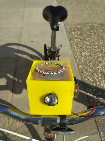
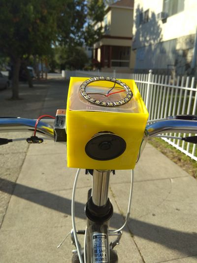
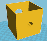
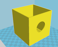
Rahee is a device which aims to replace a conventional bike accessory and irrespective of the multiple sensors it employs, it should be a bike mountable accessory after all. So to facilitate this we 3D printed a basic enclosure, which is big enough to accommodate the MCU and all the sensors, but small enough to be a mountable accessory. We needed to put together all components in a single enclosure. The enclosure includes the spacing for headlamp at the front, the anti-theft alarm speaker at the rear and slots for light sensors at the bottom left and right. The LED ring for navigation is mounted at the top of the enclosure. The device can be easily installed or removed from the bike using a velcro strap.
Hardware Interface
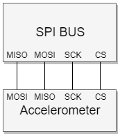
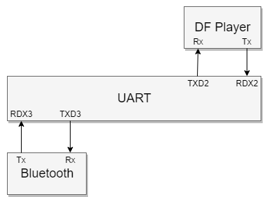
The sensors are communicating with the Master controller using their designated BUSes. The Bus map is as follows-
1.The accelerometer is communicating with the master controller using the SPI bus.
2.The Bluetooth and the DFPlayer is using the UART bus to communicate with the microcontroller and the peer device.
3. The light sensor uses an analog pin to record raw values, which are converted to digital values using ADC.
4. The PCB layout is displayed in the image below.
5. Overview of hardware interface
Software Design
Since the software for the accessory is distributed around the application and the Microcontroller. This requires for the software design of the project to be divided into into segments
a. MCU firmware design
b. Android Application design
Since, the firmware is an essential part of this project, it will be discussed first.
MCU firmware design
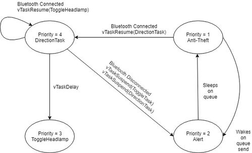
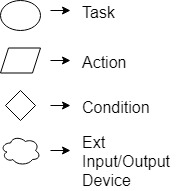
The StateMachine below captures the flow of the tasks.
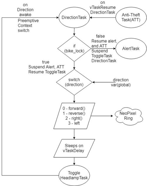
1. DirectionTask
The directionTask is the highest priority task and which starts executing as soon as the peer device is connected with the MCU. The state machine shown above captures this transition perfectly.The Direction Task drives the neopixel using the navigation data from the Rahee Android App. Priority->Highest. This priority is justified by the need of nanoseconds accuracy of the delay needed to drive the NeoPixel ring.
Pseudo Code
 a. Bluetooth module state pin is continuously monitored in this task and set to bike_lock variable
 b. Direction task will only run in case the Bluetooth module is connected
 c. If the bike_lock = 1, directionTask is executed as follows:
     i. Suspends Anti-theft and Alert Task
    ii. Resume toggleHeadlightTask
   iii. Direction variable continuously receives the signal from an Android App in toggleHeadlightTask
   vi. This Direction variable is used in a switch case to identify which direction to be displayed on the NeoPixel ring
 d. If the bike_lock = 0:
     i. Resumes Anti-theft and Alert Task
    ii. DirectionTask skips and is suspended along with the toggleHeadlightTask.
// NOTE: The Direction variable is monitored in toggleHeadlightTask on purpose since this being a critical task!
Flowchart
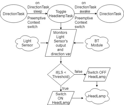
2. Toggle Headlight
This task controls the headlight. It polls the two light sensors in order to get an accurate value and drive the headlamp. The light sensors are sampled on an analog pin and using ADC, these raw values are being converted into meaningful data. Priority -> Medium.
Pseudo Code
 a. This Task monitors the Direction values from the Android App and the light sensor values continuously
 b. Depending upon the values on ADC( ambient brightness ), the headlight would toggle
 c. If lightValue < 50:
    i. the headlight turns ON
 d. Else
    i. the headlight remains OFF
Flowchart
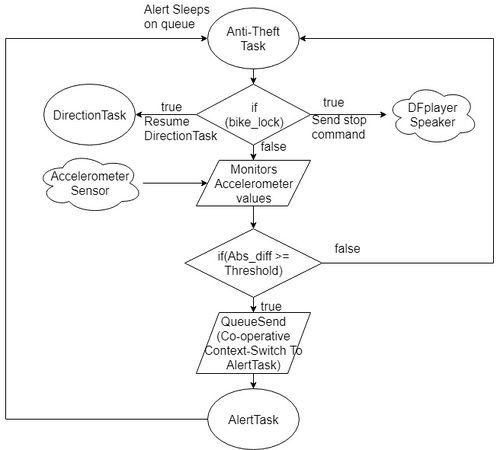
3. Antitheft
The Antitheft device can be broken down in two tasks, one which monitors the accelerometer values and then the other which plays an alert sound. The latter task comes into the picture, only if there is a jerk on the bicycle. The sensitivity of the accelerometer can be calibrated and can detect range on motions.
Pseudo Code
 a. Continuously checks the sate pin for connection
 b. If connected, i.e bike_lock = 1:
    i. The directionTask is resumed
 c. If not connected, i.e bike_lock = 0:
    i. Initial ADXL362 accelerometer 3-axis values are stored as a reference in the X, Y, Z variables
   ii. This task monitors the current accelerometer values continuously
  iii. Relative difference is calculated to identify a jerk on the bike when it is locked.
   iv. If the jerk is beyond the set threshold:
       1. new reference values are set
       2. QueueSend sends a data to the alert task:
    v. If the jerk is tolerable
       1. Continues to monitor
Flowchart
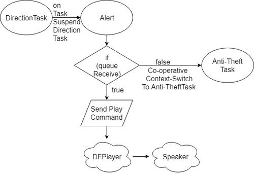
4. Alert Task
This task wakes on a QueueSend from the AntiTheft device and using the DFplayer plays the alert sound. The DF player drives the UART bus which is connected to the speaker input.
Pseudo Code
 a. Alert task sleeps on the QueueReceive for portMAXDELAY
 b. If the antiTheft task sends the data in the Queue
    i. Alert is generated and speakers produce a theft alarm
 c. If there is no data given by the Antitheft task
    i. Continues to sleep on QueueReceive
Flowchart
Android Application design
The Android App provides a simple interface for the user to communicate with the controller. It consists of two activities - Main Activity and Google Maps Activity The Main Activity enables users to Connect/Disconnect with Rahee by tapping on the Connect/Disconnect button. As soon as the app connects to the device, Google Maps Activity is launched. The user can then input the destination and get directions to there from the current location.
The activities are described in detail below:
1. Main Activity
The Main Activity allows users to Connect/ Disconnect with the device through Bluetooth. Once the user taps on the Connect button, it confirms if the Bluetooth was turned on and searches for the MAC address of Rahee in the list of active paired devices. Once the MAC address is found, it automatically launches the Google Maps Activity using an Intent. While launching the Google Maps Activity it also passes the BluetoothDevice object to enable communication in the other activity.
2. Google Maps Activity
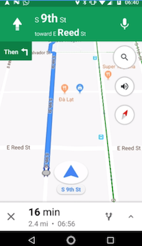
The Google Maps Activity initially displays the current location of the user. It allows the user to enter a destination address to navigate to by entering it in the Text View widget at the top of the screen. Once the destination address is entered the user can tap on the Navigate button to launch Google Maps Directions. The Google Maps Directions are configured to operate in Bike Mode and avoid Highways keeping in mind the convenience and safety. The directions also send turn by turn navigation commands over Bluetooth which is used to display directions on the LED ring on the device.
Implementation
Driving NeoPixel Ring
The Neopixel rings comes up with strict guidlines on its timing. Its hence highly critical to understand its timing diagram in order to enable transmission.The below figure shows the timing constraints of the neopixel.
The pseudo code below tries to captures these constraints .
 a.Give Reset for more than 50us.  Send 24 bits with reset according to the timing chart in between.
 b.For high, it should remain high for 600 ns
 c.For low, it should remain low for 300ns
Accelerometer Synchronization
The Accelerometer is interfaced on an SPI bus. To communicate with the accelerometer, following opcodes were sent in order to do the following operations-
 a.  0x2D to power up the sensor.
 b.  0x0E, X0F  to read the X axis of the sensor
 c.  0x11, 0x12 to read the Y axis of the sensor
 d.  0x13,0x14 to read the Z axis of the sensor
BlueTooth Communication The bluetooth communication is being done by using the UART bus. Initially the Bluetooth's baud rate and name of the device was changed. This was done by the manufacturer bluetooth's application on the play store.
 a. To change the name of the device, send the command AT+NAME= "<your device name>"
 b. To change the baudRate of the device, send the command AT+Baud= <"Desired Baud Rate">
Light Sensor
The light sensor was interfaced on an analog pin. The raw readings are then converted to digital value using ADC. Steps required to set up are-
 a. Connect the output pin of the sensor to an ADC capable pin.
 b. Convert the raw values to digital value using ADC.
Software and Hardware Implementation
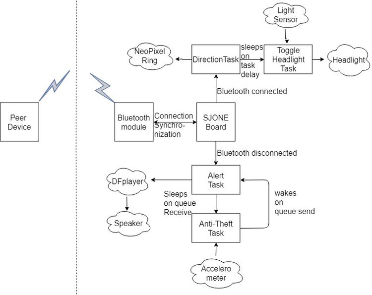
The firmware of the device uses FreeRtos to manage between different tasks. The hardware organization and the data flow between the tasks are shown as below-
In summary of the firmware design, the process starts from the bluetooth connection. If the device is connected, then the high priority task(Direction Task) Starts. While the direction task runs, all other tasks which are of low priority, wont run. As soon as the direction or the navigation ends, a task of lower priority runs- Anti Theft task starts running. A medium priority task sleeps on a queue which wakes on QueueSend from low priority task. The low priority tasks check for a motion on a bike and sends alert in queue which wakes the medium priority task. The medium priority tasks plays the sound.
Testing & Technical Challenges
1. PWM to drive the Neopixel LED
The initial design philosophy to drive the neoPixel was using PWM. However, due to the stringent timing constraints of the neopixel and the cascading effect, the PWM design was replaced with a GPIO.
Advise- understanding the PWM interrupts and using to drive the LED could have worked. It would be a good place to explore for driving the Neopixel Ring.
2. GPIO current drop
The Headlamp Led, when connected with the VCC drew 300mA, however this dropped by a factor of 30 when it was being driven by the GPIO. WorkAround- to add a gain, we used a BJT as a current amplifier.
Advise- the circuit is basic in nature and could be evolved to do more heavy lifting.
3. BLE to Bluetooth
Though BLE is almost as same as Bluetooth in functionality,but BLE can offer a considerable reduction in the power consumption. The module nrf8100 has the best documentation till date, but offers no library for the ARM-m3 series(We were not able to find one). The major challenge came when even after many attempts, the common handshake was erroneous. So instead of spending our effort to get it working, we switched to Bluetooth which is really simple to use.
Advise- to use nrf8100, the endianness is different from the LPC's SSP controller. This is a good start to figure out before working on the handshake.
4. Activity feature of accelerometer
The accelerometer ADXL362 has an in-built feature to detect the suspicious activity of the bike. ADXL362 has an interrupt pin on which these activity and other features like free fall can be configured. We tried using this feature by configuring the activity on external interrupt pin of the sensor but we got constant '0' value at the output. Currently we have implemented an algorithm to identify the motion or jerk detection, by setting a threshold, on the bike.
Advise- The activity detection algorithm is basic in nature and can be improved by using the in-built feature after perusing the datasheet.
Bug/issue name
1. Bluetooth not disconnecting(App Issue)
The application has a bug, where the bluetooth will not disconnect .
2. Error in pausing Alert Audio
The alert audio, doesnt pause. A power reset is needed for the same.
Conclusion
This project helped us learn the FreeRTOS APIs and we all can only agree here that what a nightmare this project would be if the project was implemented on a bareMetal than RTOS. Due to the various components involved in the project, it gave us a really good hands on experience in understanding the functionality of different sensors and how to use different protocols. There were some challenges which we were presented with that taught us how something as trivial as a LED can put our skills to test. Last, but not the least, this project helped us understand the project life-cycle and importance of good documentation.
Future Improvements
1. Compact Enclosure: Compact enclosure with a rigid support to fix the module on the bike's handle. Inclusion of PCB to avoid lose connection and increase compactness.
2. Headlight Brightness: Brightness can be controlled depending upon the ambient light sensed by the Light sensor
3. Fitness Activity: Can be configured to monitor and display the following:
 a. Heart-rate
 b. Calories Burnt
 c. Distance Travelled
 d. Speed
4. Voice commands: Voice commands to enable the user to navigate regardless of the display ring
5. MP3 player: DFplayer mini module can be configured to design a mp3 player enabling the user to listen to their favorite songs
6. Power consumption: Bluetooth can be switched with BLE to reduce the power consumption.
Acknowledgement
We thank Professor Preetpal Kang for teaching us embedded software and giving us this opportunity to explore the world of embedded systems by ourselves. We are also thank the CMPE-244 ISA team for being supportive and helpful throughout the project and the course.
Appendix
Project Video
Project Source Code
References
[1] CMPE 244 Lecture notes from Preetpal Kang, Computer Engineering, San Jose State University. Jan-May 2017.
[2] FreeRTOS documentations
[3] Spring 2017 and Spring 2016 Wiki reports
[4] FreeRTOS API reference
[5] Neo Pixel LED Ring datasheet
[6] HC-05 datasheet
[7] ADXL362 Accelerometer datasheet
[8] ALS PT19 datasheet
