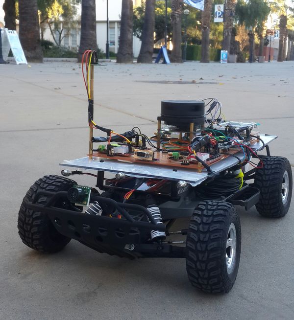
Difference between revisions of "F17: Tata Nano"
Proj user3 (talk | contribs) (→Lidar Sensor) |
Proj user3 (talk | contribs) (→Team Members & Responsibilities) |
||
| (279 intermediate revisions by 3 users not shown) | |||
| Line 1: | Line 1: | ||
| − | + | [[File:CMPE243 F17 Nano Car.jpg|thumb|600px|TATA NANO CAR|right]] | |
| − | |||
| − | |||
| − | |||
| − | |||
| − | |||
| − | |||
| − | |||
| − | |||
| − | |||
| − | |||
| − | |||
| − | |||
| − | |||
| − | |||
== Tata Nano == | == Tata Nano == | ||
Self-Navigation Vehicle Project | Self-Navigation Vehicle Project | ||
| Line 19: | Line 5: | ||
== Abstract == | == Abstract == | ||
| − | Embedded | + | Embedded systems is an amalgamation of hardware and software tools and techniques designed for a specific function. The self driving car provides an opportunity to gain valuable insight in this complex field by designing a unique system. This car has been designed to travel with the assistance of distance sensors, global positioning device and a compass. |
| − | This | + | |
| + | The car uses five micro controller units (SJOne LPC1758), each assigned a specific task. These five controllers are: | ||
| + | * Master Controller | ||
| + | * Distance Sensors Controller | ||
| + | * Geo Controller | ||
| + | * Communication/Android Controller | ||
| + | * Motor and I/O controller | ||
| + | |||
| + | These controllers broadcast data on a CAN bus. To ensure effective message communication, DBC encoding was used. DBC is a method that specifies the size, type and precision of the bytes being broadcasted. This reduces the extraneous overhead of writing code to make sense of each byte of incoming data. This ensure co-ordination among the controllers and this helps the system accomplish its goal. | ||
| + | |||
| + | A Lidar sensor was used to detect obstacles. A Lidar sensor has the added advantage that it is not only more stable, reliable but also more accurate. The Lidar used could look of obstacles in a 2-D plain. This page provides an in-depth understanding on how to use these highly efficient sensors instead of the traditionally used Sonar Sensors. | ||
| − | + | The salient features of this autonomous driving car are: | |
| − | *Android App interface | + | *Android App interface for the car |
| − | *Obstacle detection and avoidance | + | *Obstacle detection and avoidance using a superior Lidar sensor |
*Auto speed adjustment | *Auto speed adjustment | ||
*GPS Navigation | *GPS Navigation | ||
== Objectives & Introduction == | == Objectives & Introduction == | ||
| − | |||
| − | The | + | The development of an autonomous car entails a number of steps. Each step will enable a developer gain valuable insight. |
| − | The | + | A developer will have an opportunity to work with distance sensors, GPS and compass modules, Android application layer and CAN protocol, one of the most widely used communication protocols by the auto industry. The project used four micro-controllers for each module and one to ensure synchronised action between all modules. The five modules or nodes are termed as: |
| − | * Master Module - | + | * <b>Master Module</b> - It is the coordinator. It receives data from different modules and makes a decision. |
| − | * Sensor Module - | + | * <b>Distance Sensor Module</b> - This Module serves as the eyes of the car playing a key role in ensuring successful obstacle avoidance. |
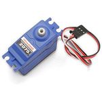
| − | * Motor Module - | + | * <b>Motor Module</b> - The forward and reverse propagation, and steering wheel of the car is controlled by this module. |
| − | * Geo Module - | + | * <b>Geo Module</b> - It provides current GPS coordinates, the destination and the correction needed to steer the car in the right direction. |
| − | * Bridge Module - The android and communication bridge controller | + | * <b>Bridge Module</b> - The android and communication bridge controller provide a list of checkpoints to the car as per what the user sets on the app. |
| + | |||
| + | The Master was the central node. It ensured accurate and smooth navigation. This module performed obstacle avoidance, steering wheel and wheel speed control and ensured the car remained on track to get to its destination via the shortest path. | ||
| + | |||
| + | The distance sensors provided information about surrounding objects that could hinder the car's journey. A very efficient Lidar sensor was used as the primary 'eyes' of the car. The Lidar sensor used in this project could only scan the hyper-plane it's laser module was placed in. While the Lidar was highly accurate and reliable, it couldn't see obstacles that didn't have points in it's hyper-plane. A Sonar Sensor was used to ameliorate the accuracy of obstacle avoidance. It assisted the Master by looking for obstacles that were shorter than the Lidar's field of detection. | ||
| + | |||
| + | The Master moved the car around by commanding the Motor Module. It adjusted vehicle speed, turned the steering wheel and reversed the direction of motion whenever needed. | ||
| − | + | The Geo module provided the current location and change of direction needed to the Master. | |
| − | + | An Android application was developed that would help a user set checkpoints and a destination. These intermediate checkpoints helped smoothly guide the car to its destination.The Bridge Module communicated with this app over Bluetooth. It stored the checkpoints entered by the user and mode this available to the Master. | |
| − | |||
| − | |||
| − | |||
| − | |||
| − | |||
| − | |||
| − | |||
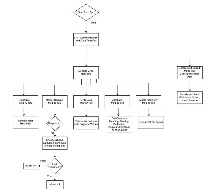
| − | [[File:CMPE243_F17_Nano_System_Workflow.gif| | + | A LCD was used to display critical system parameters. This helped monitor smooth functioning. |
| + | |||
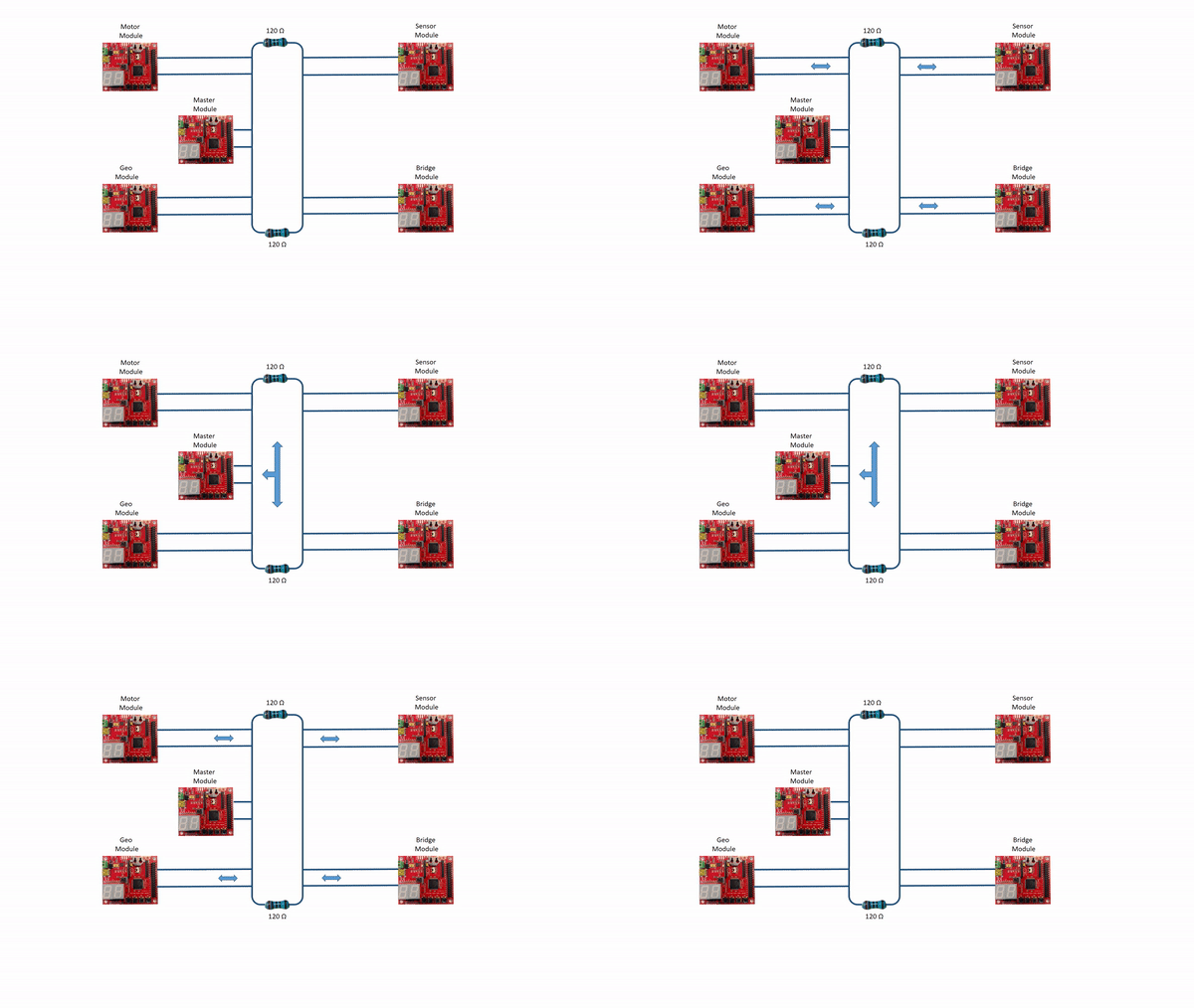
| + | CAN protocol was used for inter-node communication. A well defined DBC was used for effective message encoding and decoding. This greatly helped improve efficiency. The layout of the CAN bus was drawn on paper before being implemented. This ensured that the car didn't had to be tested for electrical failure. | ||
| + | |||
| + | The Objectives of this project were: | ||
| + | *To use CAN protocol for communication. | ||
| + | *Obstacle avoidance using LIDAR and ultrasonic sensors. | ||
| + | *Interaction between a micro-controller and a mobile application. | ||
| + | *Speed control based on the terrain. | ||
| + | *To interface a GPS module. | ||
| + | *To provide module and sensor status using the LCD or LEDs. | ||
| + | |||
| + | [[File:CMPE243_F17_Nano_System_Workflow.gif|thumb|960px|center|System workflow]] | ||
== Team Members & Responsibilities == | == Team Members & Responsibilities == | ||
| − | * Master Controller | + | * <font color="clouds">Master Controller</font> |
| − | ** Shashank Iyer | + | ** [https://www.linkedin.com/in/shashankiyer/ Shashank Iyer] |
| − | ** Aditya Choudari | + | ** [https://www.linkedin.com/in/aditya-choudhari/ Aditya Choudari] |
| − | * Geographical Controller | + | * <font color="CARROT">Geographical Controller</font> |
| − | ** Kalki Kapoor | + | ** [https://www.linkedin.com/in/kalki-kapoor/ Kalki Kapoor] |
| − | ** Aditya Deshmukh | + | ** [https://www.linkedin.com/in/aditya-deshmukh-5a7a9155/ Aditya Deshmukh] |
| − | * Communication Bridge + Android Application | + | * <font color="green">Communication Bridge + Android Application </font> |
| − | ** Ashish Lele | + | ** [https://www.linkedin.com/in/ashishlele/ Ashish Lele] |
| − | ** Shivam Chauhan | + | ** [https://www.linkedin.com/in/shivam-chauhan-a1ab2ba3/ Shivam Chauhan] |
| − | + | * <font color="blue">Motor and I/O Controller</font> | |
| − | * Motor and I/O Controller | + | ** [https://www.linkedin.com/in/venkat-raja-iyer-a0588550/ Venkat Raja Iyer] |
| − | ** | + | ** [https://www.linkedin.com/in/mehtajmanan/ Manan Mehta] |
| − | ** Manan Mehta | + | * <font color="orange">Sensor Controller</font> |
| − | * Sensor Controller | + | ** [https://www.linkedin.com/in/puspendersingh7/ Pushpender Singh] |
| − | ** Pushpender Singh | + | ** [https://www.linkedin.com/in/hugoquiroz/ Hugo Quiroz] |
| − | ** Hugo Quiroz | + | * <font color="maroon">Module Level Testing</font> |
| − | * Module Level Testing | + | ** [https://www.linkedin.com/in/mehtajmanan/ Manan Mehta] |
| − | ** Manan Mehta | + | ** [https://www.linkedin.com/in/aditya-choudhari/ Aditya Choudari] |
| − | ** Aditya Choudari | + | |
| + | ===Team Management=== | ||
| + | |||
| + | Achieving project goals in a team of 10 can be challenging due to work schedules of individuals. This issue was solved by | ||
| + | *Scheduling weekly in-person sync-ups every Tuesday only to discuss design, update goals based on new designs, offer help and inform everyone of every module's progress | ||
| + | *Scheduling weekly webcast meetings using Zoom (provided for free by SJSU to its students) on Sundays to share an update of each module. | ||
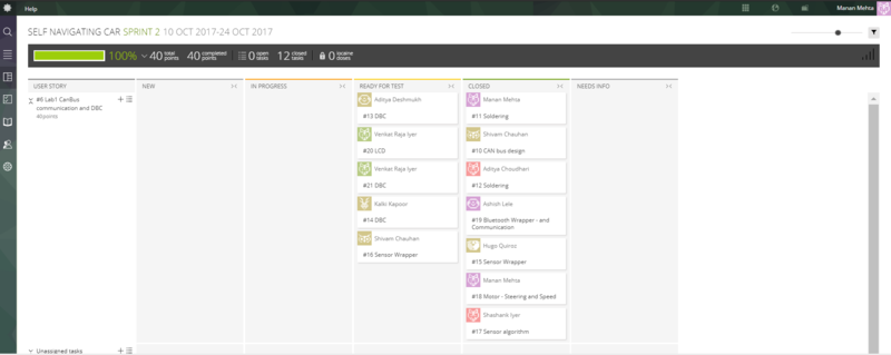
| + | *Maintaining a [https://taiga.io/ Tiaga board] to document each person's responsibility for the particular sprint | ||
| + | *Maintaining a Google Drive to share important files such as datasheets, videos, research links between team members | ||
| + | |||
| + | |||
| + | [[File:CMPE243_F17_Nano_TiagaDashboard.PNG|thumb|800px|center|Tiaga.io Dashboard Example]] | ||
==Project Schedule== | ==Project Schedule== | ||
| Line 317: | Line 333: | ||
| $400.0 | | $400.0 | ||
|- | |- | ||
| + | ! scope="row"| 12 | ||
| + | | CMPS11 Compass | ||
| + | | [https://www.dfrobot.com/product-1275.html DFRobot] | ||
| + | | 1 | ||
| + | | $40.0 | ||
| + | |- | ||
| + | ! scope="row"| 13 | ||
| + | | RPM Sensor | ||
| + | | [https://www.amazon.com/Traxxas-6520-RPM-Sensor-long/dp/B006IRXEZM Amazon] | ||
| + | | 1 | ||
| + | | $10.0 | ||
| + | |- | ||
| + | ! scope="row"| 14 | ||
| + | | 1000C PowerBoost Board | ||
| + | | [https://www.adafruit.com/product/2465 Adafruit] | ||
| + | | 2 | ||
| + | | $40.0 | ||
| + | |- | ||
| + | ! scope="row"| 15 | ||
| + | | 3.7v Li-Po Battery | ||
| + | | [https://www.adafruit.com/product/328 Adafruit] | ||
| + | | 2 | ||
| + | | $30.0 | ||
| + | |- | ||
| + | |} | ||
| − | + | == CAN protocol's DBC Design == | |
| − | + | DBC is a format that enables less hassles while developing code to either interpret data received or send data over the CAN bus. This project used DBC effectively. | |
| − | Link to the DBC file | + | A Link to the DBC file that defines the CAN communication of the system is as follows: |
[https://gitlab.com/shivam5594/Autonomous-car/blob/embedded/common_dbc/243.dbc DBC link on GitLab] | [https://gitlab.com/shivam5594/Autonomous-car/blob/embedded/common_dbc/243.dbc DBC link on GitLab] | ||
| + | |||
| + | Shown below is the DBC implementation for this project. | ||
| + | <pre> | ||
| + | VERSION "" | ||
| + | |||
| + | NS_ : | ||
| + | BA_ | ||
| + | BA_DEF_ | ||
| + | BA_DEF_DEF_ | ||
| + | BA_DEF_DEF_REL_ | ||
| + | BA_DEF_REL_ | ||
| + | BA_DEF_SGTYPE_ | ||
| + | BA_REL_ | ||
| + | BA_SGTYPE_ | ||
| + | BO_TX_BU_ | ||
| + | BU_BO_REL_ | ||
| + | BU_EV_REL_ | ||
| + | BU_SG_REL_ | ||
| + | CAT_ | ||
| + | CAT_DEF_ | ||
| + | CM_ | ||
| + | ENVVAR_DATA_ | ||
| + | EV_DATA_ | ||
| + | FILTER | ||
| + | NS_DESC_ | ||
| + | SGTYPE_ | ||
| + | SGTYPE_VAL_ | ||
| + | SG_MUL_VAL_ | ||
| + | SIGTYPE_VALTYPE_ | ||
| + | SIG_GROUP_ | ||
| + | SIG_TYPE_REF_ | ||
| + | SIG_VALTYPE_ | ||
| + | VAL_ | ||
| + | VAL_TABLE_ | ||
| + | |||
| + | BS_: | ||
| + | |||
| + | BU_: MASTER SENSOR GEO ANDROID MOTOR | ||
| + | |||
| + | BO_ 120 HEARTBEAT: 1 MASTER | ||
| + | SG_ HEARTBEAT_cmd : 0|8@1+ (1,0) [0|0] "" SENSOR,MOTOR,ANDROID,GEO | ||
| + | |||
| + | BO_ 125 MASTER_REQUEST: 1 MASTER | ||
| + | SG_ MASTER_REQUEST_cmd : 0|4@1+ (1,0) [0|0] "" ANDROID | ||
| + | |||
| + | BO_ 130 ANDROID_CMD: 1 ANDROID | ||
| + | SG_ ANDROID_CMD_start : 0|1@1+ (1,0) [0|0] "" MASTER,MOTOR | ||
| + | SG_ ANDROID_CMD_speed : 1|4@1+ (1,0) [0|0] "kmph" MASTER,MOTOR | ||
| + | SG_ ANDROID_CMD_mode : 5|1@1+ (1,0) [0|0] "" MASTER,MOTOR | ||
| + | |||
| + | BO_ 135 ANDROID_LOCATION: 8 ANDROID | ||
| + | SG_ ANDROID_CMD_lat : 0|28@1+ (0.000001,-90.000000) [-90|90] "Degrees" MASTER,MOTOR,GEO | ||
| + | SG_ ANDROID_CMD_long : 28|29@1+ (0.000001,-180.000000) [-180|180] "Degrees" MASTER,MOTOR,GEO | ||
| + | SG_ ANDROID_CMD_isLast : 57|1@1+ (1,0) [0|0] "" MASTER,MOTOR,GEO | ||
| + | |||
| + | BO_ 140 CAR_CONTROL: 2 MASTER | ||
| + | SG_ CAR_CONTROL_speed : 0|8@1+ (1,0) [11|18] "" MOTOR | ||
| + | SG_ CAR_CONTROL_steer : 8|8@1+ (1,0) [11|19] "" MOTOR | ||
| + | |||
| + | BO_ 150 SENSOR_DATA: 4 SENSOR | ||
| + | SG_ LIDAR_neg160 : 0|1@1+ (1,0) [0|1] "" MASTER,MOTOR,ANDROID | ||
| + | SG_ LIDAR_neg140 : 1|1@1+ (1,0) [0|1] "" MASTER,MOTOR,ANDROID | ||
| + | SG_ LIDAR_neg120 : 2|1@1+ (1,0) [0|1] "" MASTER,MOTOR,ANDROID | ||
| + | SG_ LIDAR_neg100 : 3|1@1+ (1,0) [0|1] "" MASTER,MOTOR,ANDROID | ||
| + | SG_ LIDAR_neg80 : 4|1@1+ (1,0) [0|1] "" MASTER,MOTOR,ANDROID | ||
| + | SG_ LIDAR_neg60 : 5|1@1+ (1,0) [0|1] "" MASTER,MOTOR,ANDROID | ||
| + | SG_ LIDAR_neg40 : 6|1@1+ (1,0) [0|1] "" MASTER,MOTOR,ANDROID | ||
| + | SG_ LIDAR_neg20 : 7|1@1+ (1,0) [0|1] "" MASTER,MOTOR,ANDROID | ||
| + | SG_ LIDAR_0 : 8|1@1+ (1,0) [0|1] "" MASTER,MOTOR,ANDROID | ||
| + | SG_ LIDAR_20 : 9|1@1+ (1,0) [0|1] "" MASTER,MOTOR,ANDROID | ||
| + | SG_ LIDAR_40 : 10|1@1+ (1,0) [0|1] "" MASTER,MOTOR,ANDROID | ||
| + | SG_ LIDAR_60 : 11|1@1+ (1,0) [0|1] "" MASTER,MOTOR,ANDROID | ||
| + | SG_ LIDAR_80 : 12|1@1+ (1,0) [0|1] "" MASTER,MOTOR,ANDROID | ||
| + | SG_ LIDAR_100 : 13|1@1+ (1,0) [0|1] "" MASTER,MOTOR,ANDROID | ||
| + | SG_ LIDAR_120 : 14|1@1+ (1,0) [0|1] "" MASTER,MOTOR,ANDROID | ||
| + | SG_ LIDAR_140 : 15|1@1+ (1,0) [0|1] "" MASTER,MOTOR,ANDROID | ||
| + | SG_ LIDAR_160 : 16|1@1+ (1,0) [0|1] "" MASTER,MOTOR,ANDROID | ||
| + | SG_ LIDAR_180 : 17|1@1+ (1,0) [0|1] "" MASTER,MOTOR,ANDROID | ||
| + | SG_ SONAR_front : 18|10@1+ (1,0) [0|645] "" MASTER,MOTOR,ANDROID | ||
| + | |||
| + | BO_ 160 GPS_DATA: 8 GEO | ||
| + | SG_ GPS_LATITUDE : 0|28@1+ (0.000001,-90.000000) [-90|90] "Degrees" MASTER,MOTOR,ANDROID | ||
| + | SG_ GPS_LONGITUDE : 28|29@1+ (0.000001,-180.000000) [-180|180] "Degrees" MASTER,MOTOR,ANDROID | ||
| + | SG_ GPS_FIX : 57|1@1+ (1,0) [0|1] "" MASTER,MOTOR,ANDROID | ||
| + | |||
| + | BO_ 170 COMPASS: 8 GEO | ||
| + | SG_ CMP_HEADING : 0|12@1+ (0.1,0) [0|359.9] "Degrees" MASTER,MOTOR,ANDROID | ||
| + | SG_ CMP_BEARING : 12|12@1+ (0.1,0) [0|359.9] "Degrees" MASTER,MOTOR,ANDROID | ||
| + | SG_ DEFLECTION_ANGLE : 24|12@1+ (0.1,-180.0) [-180.0|180.0] "Degrees" MASTER,MOTOR,ANDROID | ||
| + | SG_ DISTANCE_CHECKPOINT : 36|17@1+ (0.01,0) [0|0] "Meters" MASTER,MOTOR,ANDROID | ||
| + | |||
| + | BO_ 200 MOTOR_TELEMETRY: 8 MOTOR | ||
| + | SG_ MOTOR_TELEMETRY_pwm : 0|16@1+ (0.1,0) [0|30] "PWM" MASTER,ANDROID | ||
| + | SG_ MOTOR_TELEMETRY_kph : 16|16@1+ (0.1,0) [0|0] "kph" MASTER,ANDROID | ||
| + | |||
| + | CM_ BU_ MASTER "Master controller is heart of the system and will control other boards"; | ||
| + | CM_ BU_ MOTOR "Motor will drive the wheels of car and display data on LCD"; | ||
| + | CM_ BU_ SENSOR "Sensor will help in obstacle detection and avoidance"; | ||
| + | CM_ BU_ GEO "Geo will help in navigation"; | ||
| + | CM_ BU_ ANDROID "User sets destination and commands to start-stop the car"; | ||
| + | |||
| + | BA_ "FieldType" SG_ 120 HEARTBEAT_cmd "HEARTBEAT_cmd"; | ||
| + | |||
| + | VAL_ 120 HEARTBEAT_cmd 2 "HEARTBEAT_cmd_REBOOT" 1 "HEARTBEAT_cmd_SYNC" 0 "HEARTBEAT_cmd_NOOP" ; | ||
| + | </pre> | ||
| + | |||
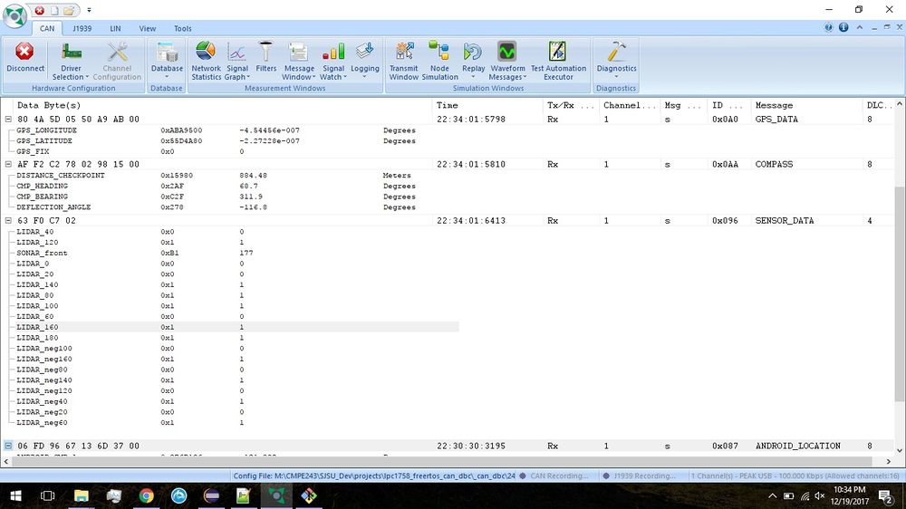
| + | A screen shot of the Bus Master Application is as shown below: | ||
| + | |||
| + | [[File:CMPE243 F17 nano BusMaster.jpeg|1000px|center|thumb|Bus Master Screen Capture]] | ||
== Sensor Controller == | == Sensor Controller == | ||
| Line 331: | Line 481: | ||
=== Hardware Design === | === Hardware Design === | ||
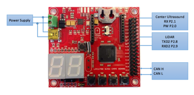
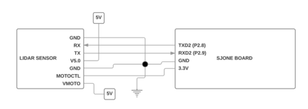
| − | The Lidar Sensor communicated to the SJONE board using UART communication protocol for data collection. The Lidar Core and Lidar Motor required | + | The Lidar Sensor communicated to the SJONE board using UART communication protocol for data collection. The Lidar Core and Lidar Motor required separate power sources and so two different 5V sources were connected to the Lidar Sensor. Lastly, the Lidar Sensor required a Motor Control Signal to control the RPM of the motor. This was simply set to the high state by connecting it to 3.3V from the SJOne Board. Setting this signal high represented setting a 100% duty cycle on the Lidar and would set the highest RPM possible on the Lidar.[[File:CMPE243 F17 nano SensorMod system.png|400px|right|thumb|Sensor Controller System Diagram]] |
| + | [[File:CMPE243 F17 nano lidar schematic_new.png|450px|left|thumb|Lidar Schematic]] | ||
| − | + | <br> | |
| + | <br> | ||
| + | <br> | ||
| + | <br> | ||
| + | <br> | ||
| + | <br> | ||
| + | <br> | ||
| + | <br> | ||
| + | <br> | ||
| + | <br> | ||
| + | <br> | ||
| + | <br> | ||
=== Hardware Interface === | === Hardware Interface === | ||
| − | + | A Lidar and sonar sensor sensor were used. The following subsections provide an in-depth description of their working | |
==== Lidar Sensor ==== | ==== Lidar Sensor ==== | ||
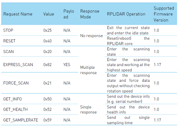
| − | Lidar Sensor is | + | Communication between the Lidar Sensor and the SJOne board is managed implemented using UART Protocol. The Rplidar System comes with several operation codes that facilitate the communication and control of the system. The operational codes are shown below. |
| − | |||
| − | + | [[File:CMPE243 F17 nano rplidar protocol.PNG|frame|200px|center|Rplidar Operation Codes]] | |
| − | [[File:CMPE243 F17 nano | + | |
| + | |||
| + | The C code implementation of the operation codes shown above is shown below - | ||
| + | bool stop_scan();//no response, lidar enters idle state | ||
| + | bool reset_core();//no response, resets lidar core | ||
| + | void start_scan();//continuous response, starts scan | ||
| + | bool start_express_scan();//continuous response, scans at highest speed | ||
| + | bool start_force_scan();//continuous response, start scan without checking speed | ||
| + | void get_info(info_data_packet_t *lidar_info);//single response, returns device info | ||
| + | void get_health(health_data_packet_t *health_data);//single response, returns device health info | ||
| + | void get_sample_rate(sample_rate_packet_t *sample_rate);//single response, returns sampling time | ||
| + | |||
| + | |||
| + | Each function shown above sends an operation code to the Lidar Sensor. The Operation Codes are listed out in an enum structure and each function sends out its respective operation code - | ||
| + | |||
| + | |||
| + | //Enumerations for Lidar Commands | ||
| + | typedef enum { | ||
| + | lidar_header = 0xA5, | ||
| + | lidar_stop_scan = 0x25, | ||
| + | lidar_reset_core = 0x40, | ||
| + | lidar_start_scan = 0x20, | ||
| + | lidar_start_exp_scan = 0x82, | ||
| + | lidar_start_force_scan = 0x21, | ||
| + | lidar_get_info = 0x50, | ||
| + | lidar_get_health = 0x52, | ||
| + | lidar_get_sample_rate = 0x59, | ||
| + | } lidar_cmd_t; | ||
| + | |||
| + | |||
| + | |||
| + | The commands above were utilized for testing and confirmation of the Lidar's functionality, however, our final design only made use of a couple relevant commands. From the three types of scans that are listed above, it was decided to use the standard scan. The start_scan() function is shown below passing the lidar_start_scan enum value as an argument to the send_lidar_command() function. The send_lidar_command() function sends out the arguments that are passed to it over UART | ||
| + | |||
| + | //Send the start scan lidar command to the lidar sensor | ||
| + | void Lidar_Sensor::start_scan() | ||
| + | { | ||
| + | send_lidar_command(lidar_start_scan); | ||
| + | } | ||
| + | |||
| + | |||
| + | void Lidar_Sensor::send_lidar_command(lidar_cmd_t lidar_cmd) | ||
| + | { | ||
| + | u2.printf("%c", lidar_header); | ||
| + | u2.printf("%c",lidar_cmd); | ||
| + | } | ||
| + | |||
| + | |||
| + | |||
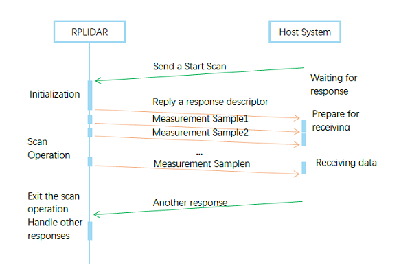
| + | In the image below we can see a visual representation of the multiple response modes that the standard scan follows. After a scan request has been sent the lidar responds by sending continuous data packets until a different request is sent such as a stop or reset request. | ||
| + | |||
| + | [[File:CMPE243 F17 nano rplidar request response.PNG|250px|frame|center|Request and Response Model]] | ||
| + | |||
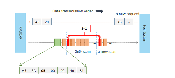
| + | The first packet sent after a start command is a response descriptor which confirms that the lidar has received the command and will begin sending 360 data. The start command is sent by writing the hex values [A5, 20] to the UART Bus. If the lidar is functioning properly and received the start command successfully it will respond with the hex values [A5, 5A, 05, 00, 00, 40, 81]. | ||
| + | |||
| + | |||
| + | [[File:CMPE243 F17 nano response stream.PNG|frame|200px|center|Start Scan Data Flow]] | ||
| + | |||
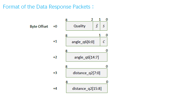
| + | After receiving the response descriptor the lidar begins sending data. The data is sent in 5-byte data chunks. The contents of the 5 bytes are shown in the image below. These 5 bytes are processed by the SJOne board to determine the angle and distance values of any object obstructing the lidar. | ||
| + | |||
| + | [[File:CMPE243 F17 nano lidar response packet format.PNG|frame|center|Data Format Breakdown]] | ||
==== Ultrasonic Sensor ==== | ==== Ultrasonic Sensor ==== | ||
| Line 391: | Line 611: | ||
=== Software Design === | === Software Design === | ||
| − | + | ||
| + | The design process of the two sensors is as follows: | ||
| + | |||
| + | ==== Ultrasound Sensor ==== | ||
| + | |||
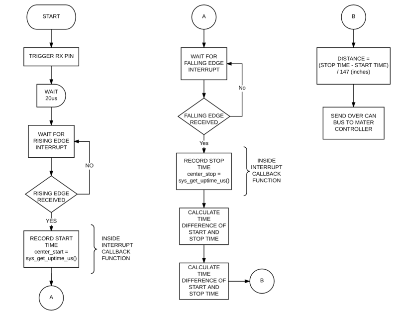
| + | Ultrasonic sensors use high-frequency sound to detect and localize objects in a variety of environments. Ultrasonic sensors measure the time of flight for sound that has been transmitted to and reflected back from nearby objects. Based upon the time of flight, the sensor then outputs a range reading. The flowchart shows the PWM implementation where RX pin is triggered and sensor start recording time of flight, start time is recorded via interrupt function and stop time is recorded when reflect back signal is received. Distance is calculated by using the time of flight divided by 147us, here 147us time is equal to 1 inch of distance. | ||
| + | [[File:CMPE243_F17_nano_ultrasound_flowchart.png|800px|thumb|center|Ultrasound Flowchart]] | ||
| + | |||
| + | ==== Lidar Sensor ==== | ||
| + | |||
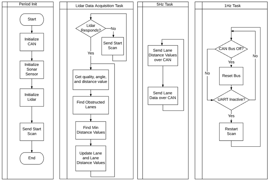
| + | For the lidar sensor, initialization was performed inside of the periodic init function along with CAN and sonar sensor followed by the first start scan command. After initialization there were three tasks managing the inner workings of the lidar sensor. The first task simply initially checks that the lidar has initialized a start scan and once this occurs the task enters a state of constantly emptying the UART queue, processing the data, and updating the current variable holding the instantaneuous lidar data. The second task is a 1Hz task that simply checks that the CAN Bus is still active and that UART is still active. Lastly, a 5Hz task sends the Lidar Lane Values and the Lidar Lane Distance Values over the CAN Bus. | ||
| + | |||
| + | [[File:CMPE243 F17 nano software model.png|900px|thumb|center|Lidar Sensor Software Model]] | ||
=== Implementation === | === Implementation === | ||
| − | + | '''Ultrasound Sensor''' | |
| + | *Configure the GPIO pins | ||
| + | **PW as input | ||
| + | **RX as output | ||
| + | *Trigger RX pin by setting it to high | ||
| + | *Input on PW calls interrupts | ||
| + | **Rising edge interrupt callback records start time | ||
| + | **Falling edge interrupt callback records stop time | ||
| + | *Distance to obscacle (inches) = (stop time- start time) / 147 (more information in datasheet) | ||
| + | *Broadcast data on CAN bus. | ||
| + | |||
| + | '''Lidar Sensor''' | ||
| + | |||
| + | *Initialize UART | ||
| + | *Send Start Command | ||
| + | *Wait for Start Command Response | ||
| + | *Periodically Empty UART Queue | ||
| + | *Divide incoming data into 18 Lanes | ||
| + | *Determine which lanes are obstructed | ||
| + | *Determine distance of obstruction | ||
| + | *Broadcast Lane and Lane Distance Values on CAN Bus | ||
| + | |||
| + | === Testing & Technical Challenges === | ||
| + | |||
| + | |||
| + | '''Lidar Sensor''' | ||
| − | + | *One challenge we faced was determining how data was to be processed and sent over CAN Bus | |
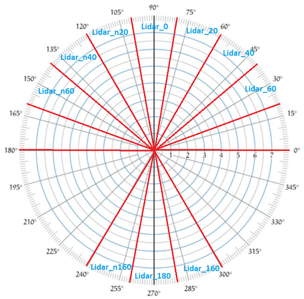
| + | **The solution to this was that we decided to divide the data into 18 Lanes of 20 degrees range and we would simply check each lane independently, determine whether there is an obstacle in within this range, and send a simple binary value indicating an obstacle or no obstacle. | ||
| + | *Another challenge we faced was that once data stream began there was no clear indication of what any arbitrary data byte corresponded to. Whether it was quality, angle, or distance value. | ||
| + | **The solution to this issue was in determining that after sending a start scan and receiving the response descriptor, the very first data packet pertained to the 0th degree and then iterated through ~360 degrees from then after. It was important to constantly empty the UART or we could lose data and consequentially lose track of the data packet being received. | ||
| + | *Another challenge faced was that under certain conditions the Lidar would fail to initialize or lose connection. | ||
| + | **There were two solutions to this issue. The first and most effective solution was that the Lidar Controller and Lidar Motor both required separate power sources. Otherwise the under conditions of low power output the Lidar Controller would successfully initialize but eventually lose connection. So we decided to give the Lidar Controller its own power source. | ||
| + | **The second solution was to check in software whether the Lidar Controller had lost connection by checking whether UART was active or not. This is effective during startup periods when initially the power source is sourcing a lot of current due to many devices starting up. If the controller ever drops connection our controller will attempt to reconnect again. | ||
| + | |||
| + | '''Ultrasound Sensor''' | ||
| + | *Inconsistent values for multiple sonar sensors | ||
| + | **Performing division operation(procession intense) inside the interrupt can cause the inconsistent values from the ultrasound sensor, make sure to move such operations outside the interrupt callback function | ||
| + | *Reflection from the ground. | ||
| + | **Solution is to mount the sensor with an angle of 20 degrees with the horizontal, this should be taken into consideration when making sensor mounts. | ||
== Motor & I/O Controller == | == Motor & I/O Controller == | ||
| Line 407: | Line 676: | ||
The Servo and DC motor are controlled via PWM and hence initial work required finding out the required duty cycle values for desired motor frequency. Higher frequency gives us a better resolution and response from the motor but for this project, a frequency of 8Hz was ideal enough to attain the required speed of vehicle and response time of the steering of the vehicle. To find out the PWM values, we connected the RC receiver of the Traxxas Slash 2WD vehicle to an oscilloscope and varied the remote controller for forward and reverse movement as well as right and left movement of the car. PWM signals were observed on the CRO and as the controller trigger was varied, the duty cycle of the PWM signal on the CRO also varied. | The Servo and DC motor are controlled via PWM and hence initial work required finding out the required duty cycle values for desired motor frequency. Higher frequency gives us a better resolution and response from the motor but for this project, a frequency of 8Hz was ideal enough to attain the required speed of vehicle and response time of the steering of the vehicle. To find out the PWM values, we connected the RC receiver of the Traxxas Slash 2WD vehicle to an oscilloscope and varied the remote controller for forward and reverse movement as well as right and left movement of the car. PWM signals were observed on the CRO and as the controller trigger was varied, the duty cycle of the PWM signal on the CRO also varied. | ||
| − | Speed control of the vehicle was carried out using a Traxxas speed sensor and a bunch of magnets. Applying the principles of a hall effect sensor, the magnets were attached to the inside of a wheel and the speed sensor was placed on the shaft of the back wheel. With every rotation, the magnets cut the field of the speed sensor giving a positive voltage to the SJone board. This positive voltage is accounted for and after | + | Speed control of the vehicle was carried out using a Traxxas speed sensor and a bunch of magnets. Applying the principles of a hall effect sensor, the magnets were attached to the inside of a wheel and the speed sensor was placed on the shaft of the back wheel. With every rotation, the magnets cut the field of the speed sensor giving a positive voltage to the SJone board. This positive voltage is accounted for and after necessary calculations, we derive the speed of the vehicle. |
To read data on the fly, LCD display by 4D systems was interfaced. The SJOne board communicates with the LCD display over UART using basic ASCII values that represent commands as well as information. The LCD graphics are preprogrammed into a MicroSD using the 4D systems workshop software and each graphical object consists of ASCII commands to control it. | To read data on the fly, LCD display by 4D systems was interfaced. The SJOne board communicates with the LCD display over UART using basic ASCII values that represent commands as well as information. The LCD graphics are preprogrammed into a MicroSD using the 4D systems workshop software and each graphical object consists of ASCII commands to control it. | ||
| Line 413: | Line 682: | ||
=== Hardware Design === | === Hardware Design === | ||
The Motor and I/O controller system consists of the following modules to perform various functions as mentioned in the description section of the table | The Motor and I/O controller system consists of the following modules to perform various functions as mentioned in the description section of the table | ||
| + | |||
| + | [[File:CMPE243 F17 Nano_MotorIO_BlockDiagram.png|500px|center|thumb|Block Diagram for Motor/IO]] | ||
| + | [[File:CMPE243_F17_Nano_System_MotorHardware.png|300px|right|thumb|Hardware Parts Of Traxxas Used]] | ||
{| class="wikitable" | {| class="wikitable" | ||
|+ Parts in Motor and IO system | |+ Parts in Motor and IO system | ||
| Line 448: | Line 720: | ||
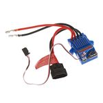
The ESC is the interface between the DC motor and SJOne board. The ESC enables speed control, protects the rest of the system from any back EMF and allows configuration of the motors in various [https://traxxas.com/sites/default/files/58034-58024-OM-N-EN-R02_0.pdf Modes (Training/Race/Sport)]. The ESC has 2 connectors the first one is a 2 wire connector, black and red which is connected to the LiPo battery that powers the motors and the second if a connector of 3 wires. 2 wires (black and red) supply a 7V DC power stepped down from the 11V lipo battery to the motors. This 7V power is used to control the servo motor using the power distribution board designed for this project. The 3rd wire (white) is a PWM input signal to the ESC from the SJOne controller that defines the speed of the motor.The ESC consists of a button to calibrate and turn on/off the ESC located on it.The ESC can be calibrated by following the steps mentioned on the [https://traxxas.com/support/Programming-Your-Traxxas-Electronic-Speed-Control Traxxas website] | The ESC is the interface between the DC motor and SJOne board. The ESC enables speed control, protects the rest of the system from any back EMF and allows configuration of the motors in various [https://traxxas.com/sites/default/files/58034-58024-OM-N-EN-R02_0.pdf Modes (Training/Race/Sport)]. The ESC has 2 connectors the first one is a 2 wire connector, black and red which is connected to the LiPo battery that powers the motors and the second if a connector of 3 wires. 2 wires (black and red) supply a 7V DC power stepped down from the 11V lipo battery to the motors. This 7V power is used to control the servo motor using the power distribution board designed for this project. The 3rd wire (white) is a PWM input signal to the ESC from the SJOne controller that defines the speed of the motor.The ESC consists of a button to calibrate and turn on/off the ESC located on it.The ESC can be calibrated by following the steps mentioned on the [https://traxxas.com/support/Programming-Your-Traxxas-Electronic-Speed-Control Traxxas website] | ||
| − | [[File:CMPE243 F17 nano ESC.jpg| | + | [[File:CMPE243 F17 nano ESC.jpg|150px|thumb|right|Traxxas ESC XL5]] |
{| class="wikitable" | {| class="wikitable" | ||
|+ ESC Pin Connection | |+ ESC Pin Connection | ||
| Line 548: | Line 820: | ||
|} | |} | ||
| − | ==== | + | ====RPM Sensor==== |
[[File:CMPE243_F17_nano_Speed_Sensor.jpg |150px|thumb|right|Traxxas Speed Sensor]] | [[File:CMPE243_F17_nano_Speed_Sensor.jpg |150px|thumb|right|Traxxas Speed Sensor]] | ||
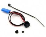
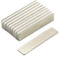
| − | To maintain the speed of the vehicle, | + | To maintain the speed of the vehicle, an RPM sensor from Traxxas was used. The assembly provided a single magnet and required mounting the sensor in the rear compartment. This setup had a major drawback of using just one magnet. One magnet did not provide enough resolution for the speed check algorithm at low speeds and small distances. Hence, we opted to mount the speed sensor on the motor shaft and attached 4 magnets on the wheel. The sensor works on the hall effect principle where it provides a current across its terminal when placed in a magnet's field. These pulses are read by the SJOne board and fed to the speed control algorithm. The RPMsensor has 3 wires, the white where are the output wire that provides the pulses to the SJone board and the other wires power the sensor. |
[[File:CMPE243 F17 nano Magnets.jpeg|120px|thumb|right|Magnets]] | [[File:CMPE243 F17 nano Magnets.jpeg|120px|thumb|right|Magnets]] | ||
| Line 557: | Line 829: | ||
|- | |- | ||
! scope="col"| S.No | ! scope="col"| S.No | ||
| − | ! scope="col"| Wires - | + | ! scope="col"| Wires - RPM Sensor |
! scope="col"| Function | ! scope="col"| Function | ||
! scope="col"| Wire Color Code | ! scope="col"| Wire Color Code | ||
| Line 577: | Line 849: | ||
|- | |- | ||
|} | |} | ||
| + | <br> | ||
| + | To install the magnets, we used the hardware materials(Allen keys and mini-lug wrench) provided with the Traxxas car. To install it we first need to remove the wheel and on the inside of the wheel, we attach the magnets using double-sided tape. | ||
==== uLCD32-PTU ==== | ==== uLCD32-PTU ==== | ||
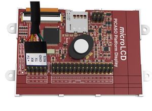
| − | uLCD32-PTU by 4D systems has a 3.2" TFT LCD Display module. The module comes with a display resolution of 240x320 pixels. 4D Systems provides a programming cable based on UART for burning the LCD code to the module. The project is burnt to a uSD card which is used for display during booting of the LCD. | + | uLCD32-PTU by 4D systems has a 3.2" TFT LCD Display module. The module comes with a display resolution of 240x320 pixels. 4D Systems provides a programming cable based on UART for burning the LCD code to the module. The project is burnt to a uSD card which is used for display during booting of the LCD. It is recommended that we use the programming adapter provided by 4D systems as it has a special reset button that can be used to download the built project to the LCD display. Using other programming cables like CP210X or another FTDI chip did not help in downloading the project to the LCD display module. Once the LCD display was configured with different widgets and screens, the motor module was coded to display information in LCD through UART (There is no need of reset button connection here as the motor does not have to send any reset signal). |
The following figure shows the programming cable and the pins used for uLCD32-PTU. | The following figure shows the programming cable and the pins used for uLCD32-PTU. | ||
| Line 665: | Line 939: | ||
The 3600 / 1000 is a constant that changes the value from m/s to km/hr | The 3600 / 1000 is a constant that changes the value from m/s to km/hr | ||
| − | + | Using interrupts, the callBack() function increments a count variable every time a magnet triggers the rpm sensor. The maintainSpeed() function then reads the count and compares it to a specified value corresponding to the speed sent by the vehicle. Using the algorithm as shown in the block diagram below, the maintainSpeed() function adjusts the duty cycle to maintain the speed of the car. | |
| − | + | void callBack() | |
| + | { | ||
| + | spd.rpm_s.cut_count++; | ||
| + | LE.toggle(2); | ||
| + | } | ||
| + | void initialize_motor_feedback() | ||
| + | { | ||
| + | eint3_enable_port2(5,eint_rising_edge,callBack); | ||
| + | } | ||
| − | [[File:CMPE243 F17 nano 1Hz Task.png| | + | ==== LCD Display ==== |
| + | |||
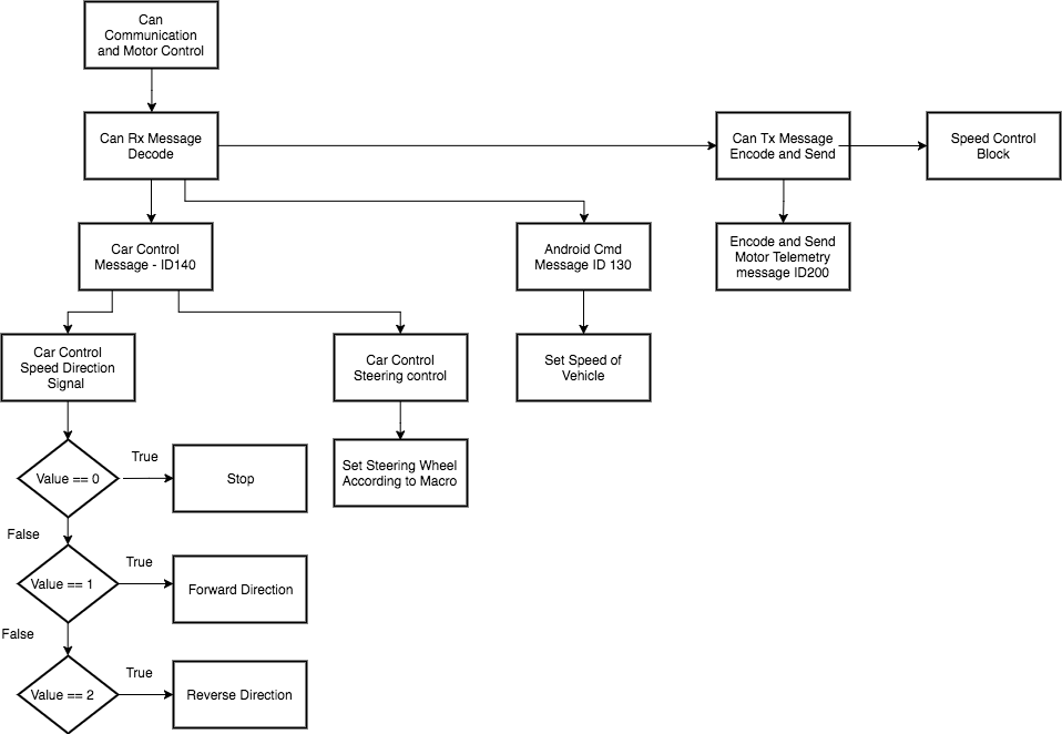
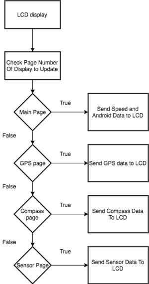
| + | uLCD-32PTU communicates with the SJ1 board over UART at a frequency of 1 Hz with a baud rate of 115200 bps. In order to reduce the amount of data transmitted over UART frequently, the code checked scans for which page is active and sends only the data of that page for display. Certain critical conditions such as bus resets are updated in the code frequently but are sent for display over UART only when the corresponding page is active. <br> Data to be sent is preprocessed to HEX code before transmitting. An example of a write command that has to be sent to write data to the 4 digit display is shown below: <br> | ||
| + | 01 0F 01 10 00 1F | ||
| + | [[File:CMPE243 F17 nano 1Hz Task.png|300px|right|thumb|1hz Task Flow Diagram]] | ||
| + | Where 01 denotes the write command, OF specifies the type of the object, 01 is the object ID, 10 and 00 are the MSB and LSB values to be displayed in the LED. The last pair of hex value is for checksum. | ||
| + | <br> | ||
| + | *''''' Programming SJ1 Board for LCD Display''''' | ||
| + | # As raw data often cannot be displayed on the LCD directly, the values to be displayed had to be converted to appropriate byte-sized values. | ||
| + | # Communication with SJOne board was established at the baud rate of 115200 bps. | ||
| + | # Commands for writing data and reading acknowledgment for various gauges were coded in the SJ1 board. | ||
| − | |||
| − | |||
*''''' Creating a project using Workshop 4 IDE and programming the LCD display''''' | *''''' Creating a project using Workshop 4 IDE and programming the LCD display''''' | ||
# After finalizing the design of the LCD's layout, a genie project was created using Workshop 4. | # After finalizing the design of the LCD's layout, a genie project was created using Workshop 4. | ||
| Line 678: | Line 968: | ||
# uLCD-32PTU was programmed with the help of programming cable provided by 4D systems. | # uLCD-32PTU was programmed with the help of programming cable provided by 4D systems. | ||
| − | + | The steps taken for interfacing the LCD display with the SJ1 board is shown on the right: | |
| − | + | <br> | |
| − | |||
| − | |||
| + | === Implementation === | ||
| + | *'''Motor Control Logic''' | ||
| + | # Initialize PWM of SJOne board | ||
| + | # Initialize ESC | ||
| + | # Receive desired speed and direction from master over CAN | ||
| + | # Set duty cycles of ESC and servo motor | ||
| + | *'''LCD Display Logic''' | ||
| + | # Set Baudrate and initialize UART communication with LCD | ||
| + | # Receive messages from various controllers to display information on LCD | ||
| + | # Perform bit and string manipulation to send data in a manner understood by the LCD | ||
| + | *'''Speed Control Logic''' | ||
| + | # Keep a count of pulses sent by RPM sensor | ||
| + | # Compare it with a reference value calculated from the desired speed set by the android controller | ||
| + | # reduce or increase duty cycle to accommodate incline and decline planes | ||
| + | <br> | ||
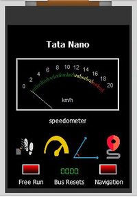
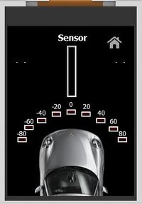
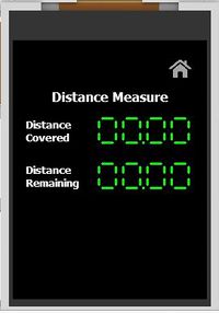
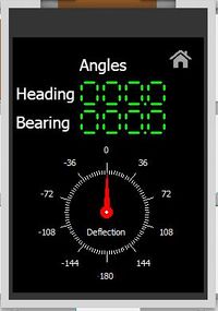
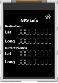
| + | '''LCD Screens''' | ||
{| | {| | ||
| − | |[[File:CMPE243 F17 nano Motor LCD | + | |[[File:CMPE243 F17 nano Motor LCD Main_Page_2.JPG|thumb|200px|left|Main Page]] |
| − | |[[File: | + | |[[File:CMPE243_F17_nano_Motor_LCD_Sensor_Page_2.JPG|thumb|200px|none|Sensor Page]] |
| − | |[[File:CMPE243 F17 nano Motor LCD | + | |[[File:CMPE243 F17 nano Motor LCD Distance_Page_2.JPG|thumb|200px|right|Distance Page]] |
|[[File:CMPE243 F17 nano Motor LCD Angles.JPG|thumb|200px|left|Angles Page]] | |[[File:CMPE243 F17 nano Motor LCD Angles.JPG|thumb|200px|left|Angles Page]] | ||
|[[File:CMPE243 F17 nano Motor LCD GPS.JPG|thumb|200px|none|GPS Page]] | |[[File:CMPE243 F17 nano Motor LCD GPS.JPG|thumb|200px|none|GPS Page]] | ||
|} | |} | ||
| − | === Testing & Technical | + | === Testing & Technical Challenges === |
| − | + | *Reverse logic of the vehicle was not a direct change of duty cycle. For example, say the duty cycle of the forward motion is 15% and the reverse is 11.5%, the vehicle which is originally at 15% going forward will not go in reverse when we give it 11.5% directly. It is required for the ESC to first receive a signal of stop (throttle initial duty cycle) and then a reverse duty cycle | |
| − | A major challenge that was faced while interfacing the LCD with the SJ1 board was that the SJ1 board was frequently getting rebooted while sending data for all metrics at once. To counteract this problem, the metrics were split into different forms(pages) for display and the data belonging to the active form alone was sent. Another challenge was that LCD does not support display of data that is more than 4 digits in length. To support display of data such as GPS coordinates, multiple 4 digit display objects had to be used with data manipulation before sending over UART. | + | *Initially the motor ESC lost its calibration often and speed control varied because of the one button interface on the ESC to turn on and calibrate it. We got the calibration steps from the Traxxas manual and had to teach various members of the testing team on how to recalibrate it if there was a case. |
| + | *A major challenge that was faced while interfacing the LCD with the SJ1 board was that the SJ1 board was frequently getting rebooted while sending data for all metrics at once. To counteract this problem, the metrics were split into different forms(pages) for display and the data belonging to the active form alone was sent. Another challenge was that LCD does not support display of data that is more than 4 digits in length. To support display of data such as GPS coordinates, multiple 4 digit display objects had to be used with data manipulation before sending over UART. | ||
== Geographical Controller == | == Geographical Controller == | ||
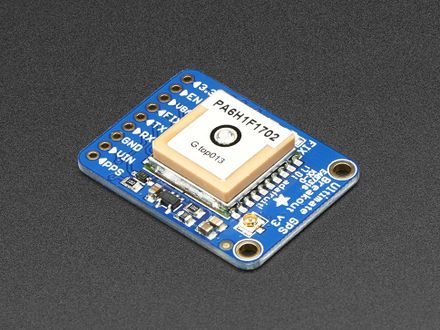
| − | Geographical Controller is one the most important controller in the car which help it to navigate to its destination. | + | Geographical Controller is one the most important controller in the autonomous car which help it to navigate to its destination. This controller consists of Global Positional System (GPS) and Compass (Magnetometer) modules. These modules continuously update the position and orientation of the car with respect to geographical north and sends the data to Master, Motor and Android controller boards. We are using Adafruit Ultimate GPS module and CMPS11. |
=== Design & Implementation === | === Design & Implementation === | ||
| − | |||
| − | The | + | The GPS module used in this project runs on UART communication protocol. Its default baud rate was 9600bps. We configured it to work on 57600bps to extract data at faster rate. The GPS module works on NMEA 0183 standards which define the electrical and data specification for communication between GPS module and its controller. We are using Recommended minimum specific GPS/Transit data (GPRMC) command. It provide us with three importatnt data which are Fix, Latitude and Longitude, required for localization and navigation of the car. The update rate of these data from GPS module is configured at 5Hz. |
| − | [[File: | + | |
| + | |||
| + | We choose compass module, CMPS11, mainly because of its tilt-compensation feature. When the RC car is in motion, there are jerks whenever the terrain is rough. Due to these jerks, the orientation of the compass around X and Y axis can change. In such scenarios, a Kalman filter combines the gyro and accelerometer to remove the errors caused by tilting. Hence the compass readings have no effect from the jerks of the car. | ||
| + | |||
| + | {| | ||
| + | |[[File:CmpE243_F17_Nano_compass.jpg|250px|thumb|none|Compass]] | ||
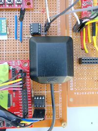
| + | |[[File:CmpE243 F17 Nano GPS module.jpg|440px|thumb|right|GPS module]] | ||
| + | |} | ||
| + | |||
| + | ====Compass Calibration==== | ||
| + | [[File:CmpE243_F17_Nano_compass_calibration.jpg|250px|Compass calibration|right|thumb]] | ||
| + | |||
| + | Calibrating the compass is a very important step in making sure that the compass gives right readings. Its purpose is to remove sensor gain and offset of both magnetometer and accelerometer, and achieves this by looking for maximum sensor outputs. | ||
| + | |||
| + | '''Entering Calibration mode''' - | ||
| + | The calibration mode is entered by sending a 3-byte sequence of 0xF0,0xF5 and then 0xF6 to the command register. These must be sent in 3 separate I2C frames. There MUST be a minimum of 20ms between each I2C frame. The LED will then extinguish and the CMPS11 should now be rotated in all directions on a horizontal plane. If a new maximum for any of the sensors is detected, then the LED will flash. When you cannot get any further LED flashes in any direction then calibration is done. | ||
| + | |||
| + | '''Exiting Calibration mode''' - | ||
| + | Once the LED flashes are over, you need to stop calibration. To exit the calibration mode, you must send 0xF8 to exit calibration mode. | ||
| + | |||
| + | '''Restoring Factory Calibration''' - | ||
| + | The compass comes with a factory calibration which gives decent output in most situations. So to move back to the original firmware calibration, we write the following to the command register in 3 separate transactions with 20ms between each transaction: 0x20,0x2A,0x60. No other command may be issued in the middle of the sequence. | ||
| + | |||
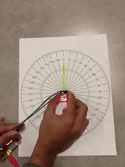
| + | The compass calibration was done as shown in the picture to the right | ||
| + | |||
| + | Final compass calibration was done within the position where the compass was mounted on the car. We still needed to calibrate the compass occasionally and the entire process took a lot of time. Hence, we decided to automate the process. | ||
| + | |||
| + | '''Calibration Automation''' - | ||
| + | We have automated the calibration process for the compass. By pressing switch 1 on the SJOne board, the compass goes into calibration mode. After we finish calibration, we press switch 2 to come out of calibration mode. If we want to restore firmware calibration, we press switch 3. | ||
| + | |||
| + | Following are the parameters which are useful in developing algorithm for GEO controller - | ||
| + | |||
| + | '''Bearing Angle''' - Bearing angle is an angle between the line, made by joining two points, with respect to Geographical north. Here, two points that are considered are - First is the current location of the car and the second point is the destination or the next checkpoint to be reached. This angle is calculated using Haversine formula. | ||
| − | + | '''Heading Angle''' - Heading angle is directly given by Compass module. It is an angle made by the current pointing direction of the car with respect to Geographical North. | |
| − | |||
| − | + | '''Deflection Angle''' - The difference of Bearing and Heading angle gives the Deflection angle. This angle is an indication of the amount of rotation the car should make to reach its destination point in a straight line. | |
| − | + | '''Distance to Checkpoint''' - This is the distance in meters between the current position of the car and the next checkpoint to be reached. | |
=== Hardware Design === | === Hardware Design === | ||
| + | The GPS module we are using is Adafruit Ultimate GPS module which has following features - | ||
| + | -165 dBm sensitivity, 10 Hz updates, 66 channels | ||
| + | 5V friendly design and only 20mA current draw | ||
| + | Breadboard friendly + two mounting holes | ||
| + | RTC battery-compatible | ||
| + | Built-in datalogging | ||
| + | PPS output on fix | ||
| + | Internal patch antenna + u.FL connector for external active antenna | ||
| + | Fix status LED | ||
| + | |||
| + | We are using the CMPS11 Magnetometer. It packs a 3-axis magnetometer, a 3-axis gyro and a 3-axis accelerometer. We can use it in Serial or I2C mode. The specifications of the module are as follows - | ||
| + | Voltage - 3.6v-5v | ||
| + | Current - 35mA Typ. | ||
| + | Resolution - 0.1 Degree | ||
| + | Accuracy - Better than 2%. after calibration | ||
| + | Signal levels - 3.3v, 5v tolerant | ||
| + | I2C mode - up to 100 kHz | ||
| + | Serial mode - 9600, 19200, 38400 baud | ||
| + | Weight - 10g | ||
| + | Size - 24.5 x 18.5 x 4.5mm(0.96 x 0.73 x 0.18") | ||
| + | |||
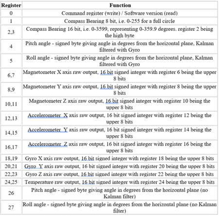
| + | We are using the compass in I2C mode of operation. The following table shows the registers and their function. | ||
| + | |||
| + | [[File:CmpE243_F17_Nano_compass_registers.png|thumb|450px|center|thumb|Registers of CMPS11]] | ||
| + | |||
| + | We are using the Compass bearing (16-bit) given by the compass registers 2 and 3 to calculate our car heading. We use the command register to put the compass into calibration mode, removing from calibration mode and restoring factory calibration. | ||
=== Hardware Interface === | === Hardware Interface === | ||
| + | |||
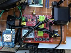
| + | Adafruit GPS module uses MTK3339 chipset which can track up to 22 satellites on 66 channels. But generally it is hard to get a fix from GPS module and it takes a while to do so. Sometimes even the data received from GPS module is not accurate. In order to solve these issues we have added two additional parts to GPS module - Coin cell and External active antenna. Coin cell added is 3V. It helps in getting fix quicker. It keeps the RTC of the module running and also retains the baud-rate of configured UART communication even after the module is powered off. External active antenna plays an important role in both providing a faster first fix and accurate GPS data. Antenna we are using is also from Adafruit which is 5 meters long and this antenna provides -165 dBm sensitivity. GPS module draws around 20-25mA and antenna draws around 10-20mA current. | ||
| + | |||
| + | Initially we had mounted the compass on the front bumper of the car (away from the motor). At this location we were getting a lot of magnetic interference due to which the compass values were not coming correct. We found that the errors increased as we took the compass closer to ground. Then we mounted the compass at a height by using stand-offs at the front of the car. This reduced the magnetic interference from ground as well as from the motor. The mount location is shown in the image below | ||
| + | |||
| + | {| | ||
| + | |[[File:CmpE243_F17_Nano_antenna.jpg|thumb|200px|Antenna|left]] | ||
| + | |[[File:CmpE243_F17_Nano_GPS_antenna.jpg|thumb|250px|GPS module with Antenna|right]] | ||
| + | |} | ||
=== Software Design === | === Software Design === | ||
| + | First initialization process take which sets the baud rate of GPS module. First command is sent using UART at 9600 bps baud-rate, and the command sent is to change the baud-rate to 57600 bps for further communications. Then various UART commands are sent to GPS module to configure it with following settings - | ||
| + | #Send only Recommended minimum specific GPS/Transit (GPRMC) data. | ||
| + | #Set the rate (echo-rate) at which the data is sent from GPS to controller board. Here it is set as 10 Hz,which is maximum. | ||
| + | #Set the rate at which fix position in GPS is updated from satellites. Here it is set as 5Hz, which is maximum. | ||
| + | So even though the fix position is updated at 5Hz, we have set the echo rate as 10 Hz from GPS module to microcontroller. So GPS module will send same data two times. This is done as it makes all the calculations and processing of data simpler in 10 Hz periodic scheduler task in microcontroller side. | ||
| + | |||
| + | Following are the UART commands for Adafruit GPS module provided for reference - | ||
| + | |||
| + | Different commands to set the update rate from once a second (1 Hz) to 10 times a second (10 Hz). | ||
| + | Note that these only control the rate at which the position is echoed, to actually speed up the position fix you must also send one of the position fix rate commands below too - | ||
| + | #define PMTK_SET_NMEA_UPDATE_100_MILLIHERTZ "$PMTK220,10000*2F" // Once every 10 seconds, 100 millihertz. | ||
| + | #define PMTK_SET_NMEA_UPDATE_200_MILLIHERTZ "$PMTK220,5000*1B" // Once every 5 seconds, 200 millihertz. | ||
| + | #define PMTK_SET_NMEA_UPDATE_1HZ "$PMTK220,1000*1F" | ||
| + | #define PMTK_SET_NMEA_UPDATE_2HZ "$PMTK220,500*2B" | ||
| + | #define PMTK_SET_NMEA_UPDATE_5HZ "$PMTK220,200*2C" | ||
| + | #define PMTK_SET_NMEA_UPDATE_10HZ "$PMTK220,100*2F" | ||
| + | Position fix update rate commands - | ||
| + | #define PMTK_API_SET_FIX_CTL_100_MILLIHERTZ "$PMTK300,10000,0,0,0,0*2C" // Once every 10 seconds, 100 millihertz. | ||
| + | #define PMTK_API_SET_FIX_CTL_200_MILLIHERTZ "$PMTK300,5000,0,0,0,0*18" // Once every 5 seconds, 200 millihertz. | ||
| + | #define PMTK_API_SET_FIX_CTL_1HZ "$PMTK300,1000,0,0,0,0*1C" | ||
| + | #define PMTK_API_SET_FIX_CTL_5HZ "$PMTK300,200,0,0,0,0*2F" | ||
| + | Set baud-rate for UART communication - | ||
| + | #define PMTK_SET_BAUD_57600 "$PMTK251,57600*2C" | ||
| + | #define PMTK_SET_BAUD_9600 "$PMTK251,9600*17" | ||
| + | Turn on only the second sentence (GPRMC) - | ||
| + | #define PMTK_SET_NMEA_OUTPUT_RMCONLY "$PMTK314,0,1,0,0,0,0,0,0,0,0,0,0,0,0,0,0,0,0,0*29" | ||
| + | Turn on GPRMC and GGA - | ||
| + | #define PMTK_SET_NMEA_OUTPUT_RMCGGA "$PMTK314,0,1,0,1,0,0,0,0,0,0,0,0,0,0,0,0,0,0,0*28" | ||
| + | Turn on ALL THE DATA - | ||
| + | #define PMTK_SET_NMEA_OUTPUT_ALLDATA "$PMTK314,1,1,1,1,1,1,0,0,0,0,0,0,0,0,0,0,0,0,0*28" | ||
| + | Turn off output - | ||
| + | #define PMTK_SET_NMEA_OUTPUT_OFF "$PMTK314,0,0,0,0,0,0,0,0,0,0,0,0,0,0,0,0,0,0,0*28" | ||
| + | For logging data in FLASH - | ||
| + | #define PMTK_LOCUS_STARTLOG "$PMTK185,0*22" | ||
| + | #define PMTK_LOCUS_STOPLOG "$PMTK185,1*23" | ||
| + | #define PMTK_LOCUS_STARTSTOPACK "$PMTK001,185,3*3C" | ||
| + | #define PMTK_LOCUS_QUERY_STATUS "$PMTK183*38" | ||
| + | #define PMTK_LOCUS_ERASE_FLASH "$PMTK184,1*22" | ||
| + | #define LOCUS_OVERLAP 0 | ||
| + | #define LOCUS_FULLSTOP 1 | ||
| + | #define PMTK_ENABLE_SBAS "$PMTK313,1*2E" | ||
| + | #define PMTK_ENABLE_WAAS "$PMTK301,2*2E" | ||
| + | Standby command & boot successful message - | ||
| + | #define PMTK_STANDBY "$PMTK161,0*28" | ||
| + | #define PMTK_STANDBY_SUCCESS "$PMTK001,161,3*36" // Not needed currently | ||
| + | #define PMTK_AWAKE "$PMTK010,002*2D" | ||
| + | Ask for the release and version - | ||
| + | #define PMTK_Q_RELEASE "$PMTK605*31" | ||
| + | Request for updates on antenna status - | ||
| + | #define PGCMD_ANTENNA "$PGCMD,33,1*6C" | ||
| + | #define PGCMD_NOANTENNA "$PGCMD,33,0*6D" | ||
| + | How long to wait when we're looking for a response - | ||
| + | #define MAXWAITSENTENCE 10 | ||
| + | To generate your own sentences, check out the MTK command datasheet and use a checksum calculator such as http://www.hhhh.org/wiml/proj/nmeaxor.html | ||
| + | |||
| + | After sending UART commands, data is stored in a buffer every 100ms. Data is parsed from the buffer and first is checked for GPS fix. If fix is received then the further data processing is done. Latitude and Longitude data of current location of car is extracted from buffer. Android board sends the Latitude and Longitude for every checkpoint and destination. | ||
| − | + | '''Bearing Angle''' is calculated using checkpoint and current car's location using following formula - | |
| + | X = cos(lat2) * sin(dLong) | ||
| + | Y = cos(lat1) * sin(lat2) - sin(lat1) * cos(lat2) * cos(dLong) | ||
| + | Bearing = atan2(X,Y) | ||
| + | where, | ||
| + | (lat1, long1) are the current location coordinates | ||
| + | (lat2, long2) are the checkpoint coordinates | ||
| + | dLong is (long2 - long1) | ||
| + | |||
| + | '''Distance to checkpoint''' is calculated using below Haversine formula - | ||
| + | a = sin²(Δφ /2) + (cos φ1 * cos φ2 * sin²(Δλ/2)) | ||
| + | c = 2 * atan2( √a, √(1−a) ) | ||
| + | Distance d = R * c | ||
| + | where, | ||
| + | Φ is latitude | ||
| + | λ is longitude | ||
| + | R is Earth’s radius = 6371 Km | ||
| + | Δφ = latitude2 – latitude1 | ||
| + | Δλ = longitude2 – longitude1 | ||
| + | |||
| + | '''Deflection Angle''' is calculated as - | ||
| + | Deflection angle = Bearing angle – Heading angle | ||
| + | if(deflection_angle > 180) | ||
| + | deflection_angle -= 360; | ||
| + | else if (deflection_angle < -180) | ||
| + | deflection_angle += 360; | ||
| + | |||
| + | We can get positive or negative deflection angle depending on the values of bearing and heading. If the deflection angle is negative, we have to go left until the deflection angle becomes zero and if the deflection angle is positive, we have to go right until deflection angle becomes zero. | ||
| + | If the deflection angle comes to be greater than 180, we subtract 360 from it. By this a very big right turn will be converted to a shorter left turn. If the deflection angle comes to be lesser than -180, we add 360 to it so that a very big left turn will be converted to a shorter right turn. | ||
=== Implementation === | === Implementation === | ||
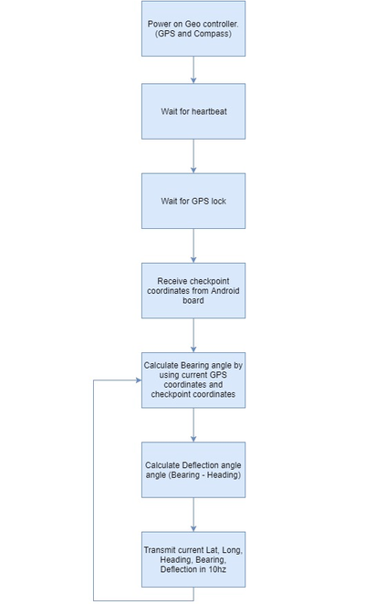
| + | We have developed following algorithm for GEO board - | ||
| + | #Initialize GPS and Compass modules. | ||
| + | #Calibrate Compass module. | ||
| + | #Get current location of the car in Latitude and Longitude from GPS. | ||
| + | #Get current Heading angle of the car from Compass. | ||
| + | #Calculate Distance to the checkpoint with help of Checkpoint data from Android and the current location of the car. | ||
| + | #Calculate Bearing angle using Checkpoint data and current location. | ||
| + | #Calculate Deflection angle with help of Bearing and Heading angle. | ||
| + | |||
| + | The algorithm for the GEO controller is as shown below: | ||
| + | |||
| + | [[File:CmpE243_F17_Nano_GEO_flowchart.png|thumb|400px|center|thumb|Geo controller algorithm]] | ||
| − | === Testing & Technical | + | === Testing & Technical Challenges === |
| + | #Compass gave wrong readings when mounted close to the ground. The solution to this was to mount the compass at a height. | ||
| + | #Compass needed to be calibrated a lot of times which wasted a lot of time during testing. The solution to this was to automate the calibration process. | ||
| + | #One of the most important thing in GPS is to get a quick fix. This was resolved with the help of Cell battery and External active antenna. | ||
| + | #Also accuracy of GPS data is another important aspect for autonomous RC car. Cell battery and external antenna does help in getting an accurate data. But still one of important factors in getting an accurate data is to keep GPS powered ON for a long time. To facilitate this, we used a separate battery to power GPS which was kept ON all the time during testing of the car. | ||
| + | #Adafruit GPS doesn't provide Latitude and Longitude data compatible with Google Maps. As Android app uses Google Maps, data received from GPS module should to be in sync with Google Maps. Following formula was used to convert GPS data to make it compatible with Google Maps - | ||
| + | For Latitude - | ||
| + | latitude = (tempLat - 100*(int)(tempLat/100))/60.0; | ||
| + | latitude += int(tempLat/100); | ||
| + | where, | ||
| + | tempLat is Latitude from Adafruit GPS module | ||
| + | latitude is Final latitude compatible with Google Maps | ||
| + | For Longitude - | ||
| + | longitude = (tempLon - 100*(int)(tempLon/100))/60.0; | ||
| + | longitude += int(tempLon/100); | ||
| + | where, | ||
| + | tempLon is Longitude from Adafruit GPS module | ||
| + | longitude is Final longitude compatible with Google Maps | ||
== Communication Bridge Controller == | == Communication Bridge Controller == | ||
| Line 731: | Line 1,214: | ||
=== Hardware Design === | === Hardware Design === | ||
| + | |||
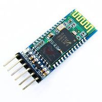
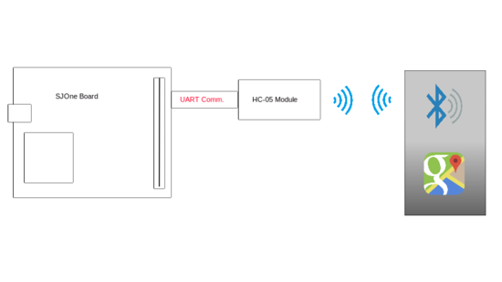
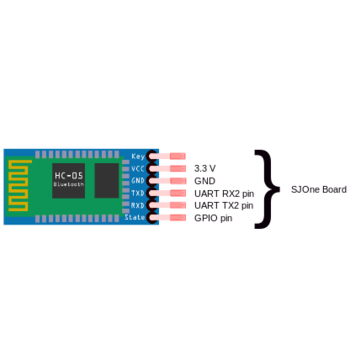
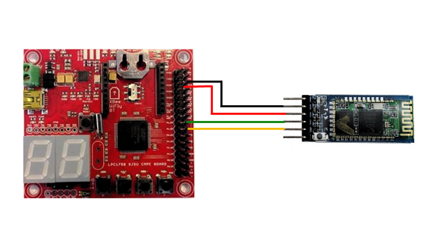
HC-05 module was chosen as a better fit for this project. It is a serial to Bluetooth converter with a very compact hardware design. It supports Enhanced Data Rate Modulation with complete 2.4GHz radio transceiver and baseband. It's noticeable features pertaining to the project are low power operation (1.8 - 3.6 V) and programmable baud rate. Different settings of the module can be configured using AT commands. | HC-05 module was chosen as a better fit for this project. It is a serial to Bluetooth converter with a very compact hardware design. It supports Enhanced Data Rate Modulation with complete 2.4GHz radio transceiver and baseband. It's noticeable features pertaining to the project are low power operation (1.8 - 3.6 V) and programmable baud rate. Different settings of the module can be configured using AT commands. | ||
Android Studio is used for creating an interactive Android application, Android Studio is available by Google for free, It's an intelligent software which helps programmer or developer with little or no knowledge of Java programming language to develop a good piece of code with high code readability and re-usability. | Android Studio is used for creating an interactive Android application, Android Studio is available by Google for free, It's an intelligent software which helps programmer or developer with little or no knowledge of Java programming language to develop a good piece of code with high code readability and re-usability. | ||
| − | [[File:CMPE243_F17_nano_BTmod.jpg| | + | [[File:CMPE243_F17_nano_BTmod.jpg|200px|thumb|left|Bluetooth Module]] |
[[File:hardware_design_tatanano.png|550px|thumb|center|Overview of hardware implementation]] | [[File:hardware_design_tatanano.png|550px|thumb|center|Overview of hardware implementation]] | ||
| − | |||
=== Hardware Interface === | === Hardware Interface === | ||
| Line 789: | Line 1,272: | ||
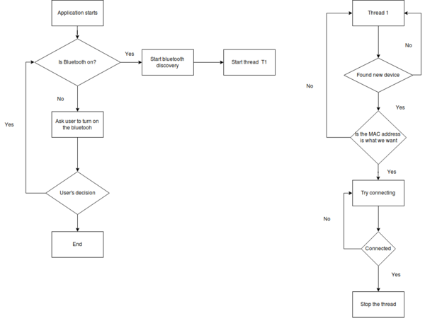
[[File:Diagram.png|600px|centre|thumb|Flow chart for home page]] | [[File:Diagram.png|600px|centre|thumb|Flow chart for home page]] | ||
| − | |||
| − | |||
| − | |||
| − | |||
| − | |||
| − | |||
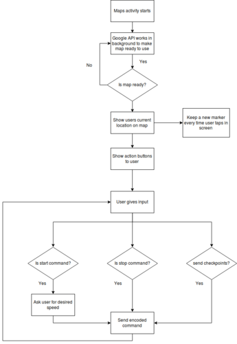
* '''Google Maps (Maps activity):''' | * '''Google Maps (Maps activity):''' | ||
| Line 806: | Line 1,283: | ||
|} | |} | ||
| − | ==== | + | ==== SJOne Board ==== |
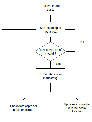
The controller handles the communication between the Android Application and the Car through the HC-05 Bluetooth Module. | The controller handles the communication between the Android Application and the Car through the HC-05 Bluetooth Module. | ||
All communication between the controller and the App takes place in a 1Hz periodic task. 1Hz task allows enough time for a string with a high number of checkpoints to get parsed completely which might not be the case with other higher frequency tasks. | All communication between the controller and the App takes place in a 1Hz periodic task. 1Hz task allows enough time for a string with a high number of checkpoints to get parsed completely which might not be the case with other higher frequency tasks. | ||
| − | The communication depends on the Start signal sent from the App to the controller. The controller also receives the desired speed and selected checkpoints along with the Start signal. On receiving the Start signal, the controller starts sending checkpoints based on request from the Master. It also receives GPS and Compass data and sends it to the App to display it. All communication stops when the App sends the Stop signal. | + | The communication depends on the Start signal sent from the App to the controller. The controller also receives the desired speed and selected checkpoints along with the Start signal. On receiving the Start signal, the controller starts sending checkpoints based on a request from the Master. It also receives GPS and Compass data and sends it to the App to display it. All communication stops when the App sends the Stop signal. |
A flow diagram of the 1Hz task is shown below: | A flow diagram of the 1Hz task is shown below: | ||
| − | [[File:1Hz Task Flow Diagram.JPG|700px|thumb| | + | [[File:1Hz Task Flow Diagram.JPG|700px|thumb|center|1 Hz Task Flow Diagram]] |
=== Implementation === | === Implementation === | ||
| + | |||
| + | ==== Android Application ==== | ||
| + | |||
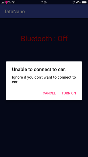
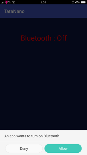
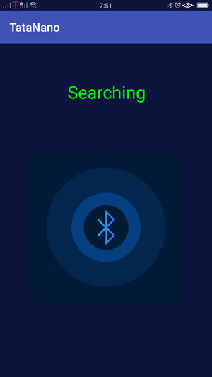
| + | Implementation of android application was easy until Bluetooth socket wan not introduced. Thanks to Google for their awesome APIs (of course they Unit test their code), which made it easier to debug the issue. Bluetooth socket programming becomes tricky when it comes to | ||
| + | |||
| + | {| | ||
| + | |[[File:App_connection1.png|300px|left|thumb|Asking user to turn on bluetooth-1]] | ||
| + | |[[File:App_connection2.png|300px|center|thumb|Asking user to turn on bluetooth-2]] | ||
| + | |[[File:App_searchingDevice.png|300px|right|thumb|searching for car]] | ||
| + | |} | ||
| + | |||
| + | |||
| + | {| | ||
| + | |[[File:LiveData1.png|300px|left|thumb|Testing right angle turn]] | ||
| + | |[[File:LiveData2.png|300px|center|thumb|Testing U turn from second last checkpoint and destination is near the starting point]] | ||
| + | |[[File:LivaData3.png|300px|right|thumb|Final application testing where it updates checkpoints as soon as it reaches there]] | ||
| + | |} | ||
=== Testing & Technical Challenges === | === Testing & Technical Challenges === | ||
| Line 833: | Line 1,327: | ||
==== Micro-controller end in freeRTOS ==== | ==== Micro-controller end in freeRTOS ==== | ||
| + | |||
| + | * '''Parsing a large number of checkpoints:''' Initially, the checkpoints sent from the Android App were being received in the 10Hz periodic function. The controller allowed reception and parsing of a small number of checkpoints but the 10Hz task would overrun while parsing a large number of checkpoints (more than 20). Moving the parsing code to the 1Hz task helped solve this issue. | ||
| + | |||
| + | * '''Retaining old checkpoint data:''' On sending the Start command to the controller, it would store all the selected checkpoints. On sending the Stop command and re-sending the Start command along with new checkpoints, the controller would still retain some of the old checkpoint data and negatively affect appropriate navigation. This issue was solved by clearing all buffers holding the checkpoint data whenever a Stop command was sent. | ||
== Master Controller == | == Master Controller == | ||
=== Design & Implementation === | === Design & Implementation === | ||
| + | The master, also the heart and brain of this design, takes a coordinated decision based on data provided by other controllers and performs the necessary operations namely obstacle avoidance and navigation. The master controller is the central decision maker. The necessary components that help master controller make all the decisions are depicted in the following diagram: | ||
| + | |||
| + | [[File:CMPE243_F17_tatanano_Master_peripherals.JPG|500px|thumb|centre|Interaction between master and peripherals]] | ||
| + | |||
| + | The master receives checkpoint co-ordinates from the 'Android-board', must steer the car based on the data provided by the 'GEO-board', knows how far it is from it's destination based on the reading from the 'GPS-board' and must preemptively avoid obstacles based on the information the 'Sensor-board' provides. | ||
| + | |||
| + | The Master also sends out periodic synchronisation messages to all these devices, colloquially called 'heartbeat' signals. The other boards check for this signal every second. In it's absence, the sensors suspend normal operation and go into wait state until the heartbeat resumes. This feature ensures that if an adversary affects the Master, the car halts immediately. | ||
=== Hardware Design === | === Hardware Design === | ||
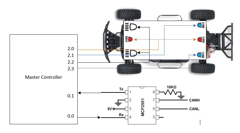
| + | The master board has fewer hardware connections. The hardware for master consists of connections for CAN transceiver and I/O lines for turn indicators and headlights. All the I/O for turn indicators and headlights are active low GPIO connections. | ||
| − | === Hardware | + | === Hardware Implementation === |
| + | Following diagram shows the hardware connections for the master controller. | ||
| + | [[File:CMPE243_F17_tatanano_Master_connections.PNG|frame|center|Master Controller Connections]] | ||
| + | The following table shows the pin connections for the master controller. | ||
| + | {| class="wikitable" | ||
| + | |- | ||
| + | ! align="center"|S.R. | ||
| + | ! align="center"|Master Controller Pins | ||
| + | ! align="center"|Connected To | ||
| + | |- | ||
| + | ! scope="row" align="center"|1 | ||
| + | | scope="row" align="center"|GND | ||
| + | | scope="row" align="center"|GND of CAN Transceiver | ||
| + | |- | ||
| + | ! scope="row" align="center"|2 | ||
| + | | scope="row" align="center"|P0.1 (RXD3) | ||
| + | | scope="row" align="center"|TXDof CAN Transceiver | ||
| + | |- | ||
| + | ! scope="row" align="center"|3 | ||
| + | | scope="row" align="center"|P0.0 (TXD3) | ||
| + | | scope="row" align="center"|RXD of CAN Transceiver | ||
| + | |- | ||
| + | ! scope="row" align="center"|4 | ||
| + | | scope="row" align="center"|P2.0 (GPIO active low) | ||
| + | | scope="row" align="center"|Cathode of STOP (red) LED indicators | ||
| + | |- | ||
| + | ! scope="row" align="center"|5 | ||
| + | | scope="row" align="center"|P2.1 (GPIO active low) | ||
| + | | scope="row" align="center"|Cathode of right (blue) LED indicators | ||
| + | |- | ||
| + | ! scope="row" align="center"|6 | ||
| + | | scope="row" align="center"|P2.2 (GPIO active low) | ||
| + | | scope="row" align="center"|Cathode of Headlights | ||
| + | |- | ||
| + | ! scope="row" align="center"|7 | ||
| + | | scope="row" align="center"|P2.3 (GPIO active low) | ||
| + | | scope="row" align="center"|Cathode of left (blue) LED indicators | ||
| + | |- | ||
| + | |} | ||
=== Software Design === | === Software Design === | ||
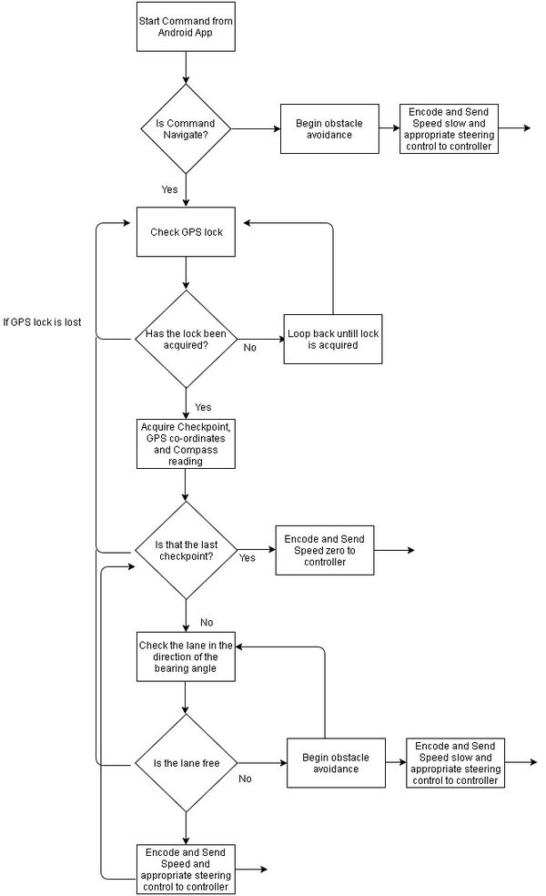
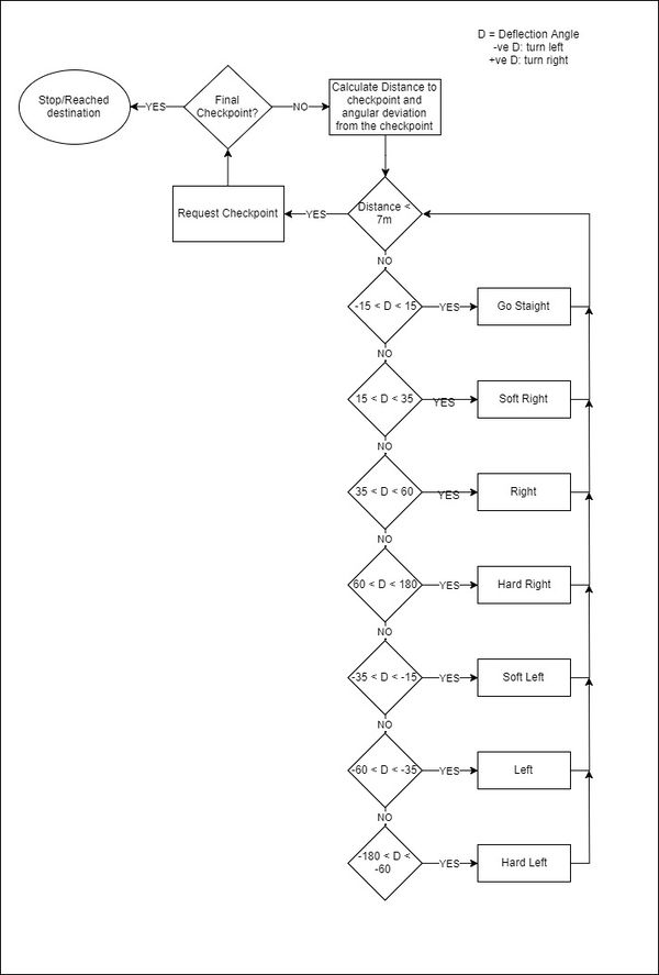
| + | The user defines a set of checkpoints using the developed app. These checkpoints are sent to the Android board. The navigation process begins once a 'start' command is sent from the mobile application. | ||
| + | |||
| + | The car reads the value from the GPS module to determine its Euclidean distance from the first checkpoint. It also checks the value on the compass to know which direction it should preferably move in. | ||
| + | |||
| + | The sensor readings help it ascertain that there isn't an obstacle to hinder its movement in the determined direction. | ||
| + | |||
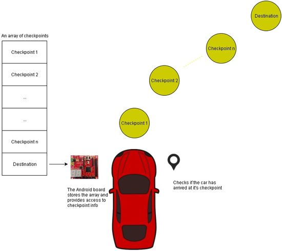
| + | The car begins navigating its way from its current location to the enlisted checkpoints. When the car arrives at a checkpoint, the master controller requests the 'Android-board' to send it the next checkpoint from it's array. | ||
| + | A schematic representing these two processes is depicted as follows: | ||
| + | |||
| + | {| | ||
| + | |[[File:CMPE243_F17_tatanano_Master_checkpoint.JPG|550px|thumb|right|Checkpoint acquiring algorithm]] | ||
| + | |[[File:CMPE243_F17_tatanano_Master_nav.JPG|534px|thumb|left|The navigation algorithm]] | ||
| + | |} | ||
| + | |||
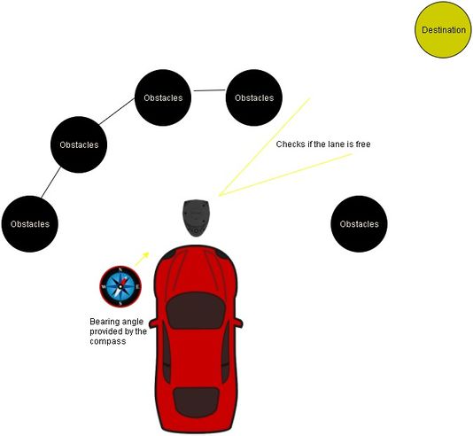
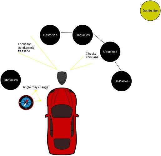
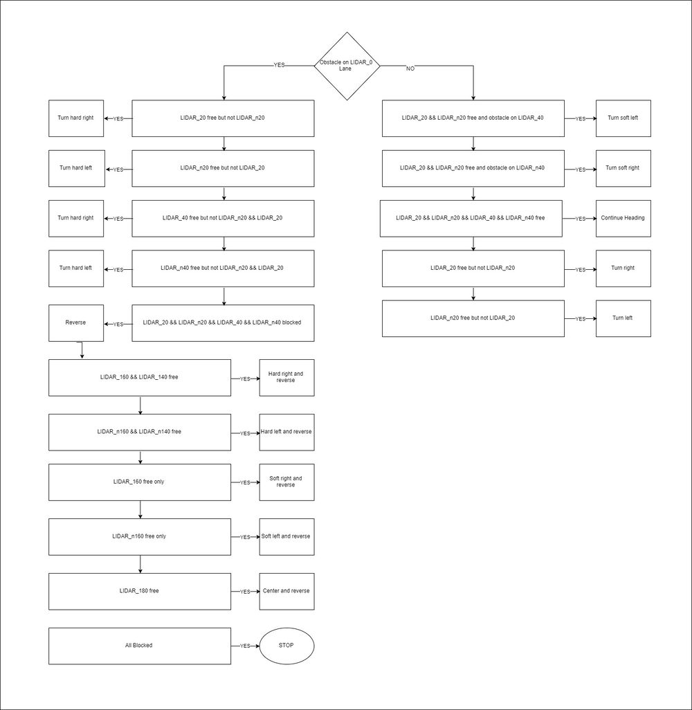
| + | More often than not, the sensors will spot obstacles in the direction that the master decides to move. An effective obstacle avoidance algorithm was implemented to deterministically avoid obstacles spotted by the sensors. | ||
| + | |||
| + | If an obstacle is detected in the chosen lane, the master controller looks for another free lane. Once found, it commands the steering controller to move in the determined direction. The master also reduces the speed of forward propogation until the spotted obstacles have been avoided and a clear and straight path from its current location to a checkpoint or destination is available. | ||
| + | |||
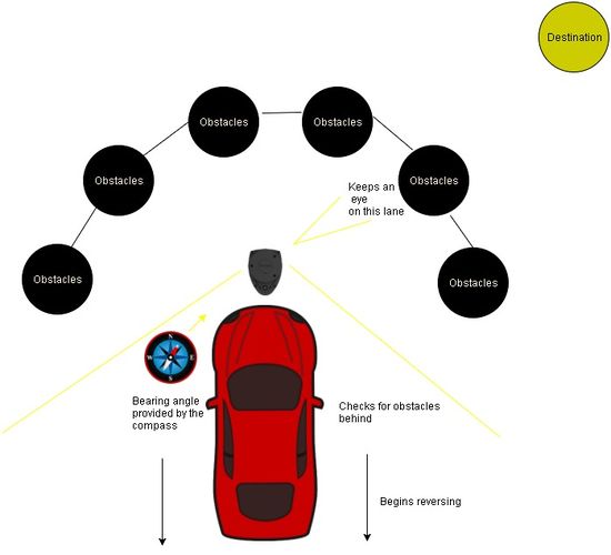
| + | At times, the car can find itself rushing towards a wall. If the sensor's determine that there is no free space for the vehicle to move, the master promptly commands the motor controller to apply the brakes. | ||
| + | This is followed by a reverse command, all while the master commands the steering controller to move in a direction that will realign the car in a better way to avoid the wall. | ||
| + | |||
| + | Once the sensors see free space available ahead, the master ensures that the car resumes its journey toward its destination. | ||
| + | |||
| + | A schematic showing the aforementioned process is shown below: | ||
| + | |||
| + | {| | ||
| + | |[[File:CMPE243_F17_tatanano_Master_obstacle.JPG|515px|thumb|right|Obstacle Avoidance algorithm]] | ||
| + | |[[File:CMPE243_F17_tatanano_Master_rev.JPG|550px|thumb|left|Reverse logic]] | ||
| + | |} | ||
| + | |||
| + | The overview operation of the master is given in the flow graph below: | ||
| + | [[File:CMPE243_F17_tatanano_Master_overall.JPG|600px|thumb|centre|Control flow of the master]] | ||
| + | |||
| + | === Software Implementation === | ||
| + | The master code can be classified into 4 groups handling different functionality. | ||
| + | * Heartbeat | ||
| + | * Indicators | ||
| + | * Obstacle Avoidance | ||
| + | * Navigation | ||
| + | |||
| + | {| class="wikitable" | ||
| + | |- | ||
| + | ! align="center"|Periodic task | ||
| + | ! align="center"|Functionality | ||
| + | |- | ||
| + | ! align="center"|1 Hz | ||
| + | | align="center"|Heartbeat and Indicators | ||
| + | |- | ||
| + | ! align="center"|10 Hz | ||
| + | | align="center"|Obstacle Avoidance and Navigation | ||
| + | |- | ||
| + | |} | ||
| + | |||
| + | ==== Heartbeat ==== | ||
| + | The master sends a heartbeat signal, at 1 Hz frequency, to all the modules along with a specific command. The command value can be: | ||
| + | <b>SYNC | | ||
| + | REBOOT | | ||
| + | NOOP</b> | ||
| + | When the car is powered ON, the master controller board will boot up and will send REBOOT command to all controllers. This is done to ensure that all other boards start after the master controller starts so that there is no deviation in the deterministic behavior of the system. If the other controllers boot after the master, they will ignore the REBOOT command and will not reboot again. | ||
| + | Once this is done, the master will send NOOP command with every heartbeat signal. All other boards will be dormant while the heartbeat command is NOOP. They will not transmit anything on the CAN bus (except for android/bridge controller). | ||
| + | Once START is given from the android application, the bridge controller will send master START command along with MODE of operation. The operation MODE can be: <b>Free Run or Navigation </b>. Also, with START, the master controller will send SYNC command with heartbeat which will cause other boards to come out of dormant mode and actively transmit data on CAN bus. | ||
| + | During the free run mode, the master will ignore values put on the CAN bus by GPS controller and only do the obstacle avoidance using sensor data. During navigation mode, if the system is unable to receive GPS lock or GPS lock is lost, the master controller will stop the car until it receives GPS lock. | ||
| + | |||
| + | ==== Indicators ==== | ||
| + | This function will update the STOP, REVERSE and left or right turn light indicators. This function also turns ON/OFF the car's headlights according to the ambient lighting of the environment. This function also displays some debugging data on the 7 segment LED display such as 'EE' for expecting new checkpoint, 'LC' for last checkpoint and 'HH' for final destination reached. This tasks runs in 1 Hz periodic task. | ||
| − | === | + | ==== Obstacle Avoidance ==== |
| + | One of the most important function of the master controller is to make sure that the car reached it's destination without crashing into obstacles. The obstacle avoidance code handled it in free run mode as well as the navigation mode. We are using LIDAR sensor to detect obstacles. The LIDAR sensors looks for obstacle within 2m range in all directions. To reduce the computation (if...else statements), we divided the LIDAR data into 18 zones, each of 20°. This can be visualized in the diagram below. | ||
| + | [[File:CMPE243_F17_tatanano_Master_lidar.PNG|600px|thumb|centre|LIDAR zones]] | ||
| + | |||
| + | For the system to detect small obstacles which lie below the scanning plan of LIDAR, we have used one ultrasonic sensor in front. We have set the critical threshold for sonar sensor as 60cm. At this distance, the car will stop and go reverse no matter what speed and mode it was initially running at. | ||
| + | #define sonar_critical 60 | ||
| + | #define sonar_warning 90 | ||
| + | The sonar warning value is just for alerting the master that the obstacle detected by LIDAR and sonar in front of the car is less than 1m ahead. The obstacle avoidance algorithm is explained in the following flow graph: | ||
| + | [[File:CMPE243_F17_tatanano_Master_obstacle_avoidance.JPG|1000px|thumb|centre|Obstacle Avoidance Algorithm]] | ||
| + | |||
| + | ==== Navigation ==== | ||
| + | Once the car can avoid obstacles, the next objective is to take car to it's destination. Master accomplishes this task by analyzing data from GEO controller. On start, the master if all the conditions are correct (GPS lock available and navigation MODE is true) will request bridge controller for checkpoint. The bridge controller provides the checkpoint latitude and longitude along with indicator 'isLast' which indicates whether the current checkpoint sent is the last one (destination). These values are used by GPS controller to determine the distance to checkpoint and deflection angle or the deviation in movement of car with respect to the checkpoint. Master uses these 2 values to navigate the car to it's destination. The obstacle avoidance has higher priority than navigation and hence, the car will corrects it's movement only when it determines the path ahead to be free of obstacles. On reaching the final destination, the master controller sends NOOP to all the controller in it's heartbeat. Thus, all other boards become dormant and stop sending data on CAN bus. | ||
| + | The navigation algorithm using distance and deflection angle is explained in the flow graph below: | ||
| + | [[File:CMPE243_F17_tatanano_Master_obstacle_guidance.JPG|600px|thumb|centre|Navigation Algorithm]] | ||
=== Testing & Technical Challanges === | === Testing & Technical Challanges === | ||
| + | As master controller depends on data from all other boards in a deterministic (timely and as expected) manner, there were several testing issues even though we had unit tested the code and had code reviews before integration. | ||
| + | * Problem Initially, when we used a single battery to power all the components, when battery was low, the lidar and sonar values were inaccurate. This problem was eventually solved by using separate battery to power Lidar along with GPS and HC05. | ||
| + | * Many times, the jumper wires came loose causing certain components to fail. During the demo too, the power supply line to HC05 BT module became loose and hence, the connectivity was severed. This issue was solved by soldering the wires wherever possible. This eliminated loose connections and bouncing effect of the wires. | ||
| + | * The CAN RX/TX buffer size for master module was 10 initially as we had less number of CAN messages. But after GPS and android messages were added to the system, the CAN buffer on master became full and some messages were rejected. This caused failure of state machine on certain occasion. We increased the buffer size, but increasing the buffer size increased processing time (as we had CAN bypass filter). Finally, we reduced number of messages by combining and removing the unnecessary messages and kept buffer size at 25. | ||
| + | * As the resolution (number of zones/lanes) provided by LIDAR sensor was high, the master code had more cases to handle. e.g. the sonar sensor has 3 zones in front while the LIDAR was programmed to give 9 lanes in front of which we used 5 lanes for navigation. | ||
| + | |||
| + | == Testing & Technical Challenges - Overall System == | ||
| + | === Testing === | ||
| + | ==== Software Testing - Unit Tests ==== | ||
| + | *In order to ensure that all modules are working as expected, unit testing was performed using CGreen to verify the functionality of all algorithms including functions used for bit manipulation, conversion of numbers from one format to another. Proper testing of all modules before integration ensured that there were no problems with Software resulting in quick identification of problems in hardware. | ||
| + | |||
| + | ==== Lidar Algorithm ==== | ||
| + | |||
| + | Shown below is one of the unit tests used on the Lidar processing algorithm. The test simulates a full 360 range of data on the lane_algorithm() function which makes use of angle_value_deg and distance_value_cm. After one simulated scan, lane_algorithm() function updates lane_lut[] array and the test function ensures that the values in lane_lut[] array equal the values in bunk_lanes_high[] array. | ||
| + | |||
| + | Ensure(test_360_range_once) | ||
| + | { | ||
| + | |||
| + | for(int i = 0; i < 359;i++) | ||
| + | { | ||
| + | angle_value_deg = i; | ||
| + | distance_value_cm = test_distance_values[6]; | ||
| + | lane_algorithm(); | ||
| + | } | ||
| + | |||
| + | assert_equal(lane_lut[0], bunk_lanes_high[0]); | ||
| + | assert_equal(lane_lut[1], bunk_lanes_high[1]); | ||
| + | assert_equal(lane_lut[2], bunk_lanes_high[2]); | ||
| + | assert_equal(lane_lut[3], bunk_lanes_high[3]); | ||
| + | assert_equal(lane_lut[4], bunk_lanes_high[4]); | ||
| + | assert_equal(lane_lut[5], bunk_lanes_high[5]); | ||
| + | assert_equal(lane_lut[6], bunk_lanes_high[6]); | ||
| + | assert_equal(lane_lut[7], bunk_lanes_high[7]); | ||
| + | assert_equal(lane_lut[8], bunk_lanes_high[8]); | ||
| + | assert_equal(lane_lut[9], bunk_lanes_high[9]); | ||
| + | assert_equal(lane_lut[10], bunk_lanes_high[10]); | ||
| + | assert_equal(lane_lut[11], bunk_lanes_high[11]); | ||
| + | assert_equal(lane_lut[12], bunk_lanes_high[12]); | ||
| + | assert_equal(lane_lut[13], bunk_lanes_high[13]); | ||
| + | assert_equal(lane_lut[14], bunk_lanes_high[14]); | ||
| + | assert_equal(lane_lut[15], bunk_lanes_high[15]); | ||
| + | assert_equal(lane_lut[16], bunk_lanes_high[16]); | ||
| + | assert_equal(lane_lut[17], bunk_lanes_high[17]); | ||
| + | } | ||
| + | TestSuite *my_tests() | ||
| + | { | ||
| + | TestSuite *suite = create_test_suite(); | ||
| + | add_test(suite, test_lane_lut); | ||
| + | add_test(suite, test_angle_1); | ||
| + | add_test(suite, test_angle_2); | ||
| + | add_test(suite, test_angle_3); | ||
| + | add_test(suite, test_full_range_once); | ||
| + | add_test(suite, testing_each_lane); | ||
| + | add_test(suite, test_lane_transitions); | ||
| + | add_test(suite, test_360_range_once); | ||
| + | return suite; | ||
| + | } | ||
| + | int main(int argc, char **argv) | ||
| + | { | ||
| + | lidar_init(); | ||
| + | TestSuite *suite = create_test_suite(); | ||
| + | add_suite(suite, my_tests()); | ||
| + | return run_test_suite(suite, create_text_reporter()); | ||
| + | } | ||
| + | |||
| + | ==== GEO Algorithm ==== | ||
| + | |||
| + | An example unit test for converting GEO coordinates to the required values before writing to the LCD is shown below: | ||
| + | |||
| + | Ensure(testing_lcd) | ||
| + | { | ||
| + | /** | ||
| + | * Tests for displaying Geo values | ||
| + | */ | ||
| + | convert_geo(360123456, &geo_left, &geo_right); | ||
| + | assert_that(geo_left, is_equal_to(36012)); | ||
| + | assert_that(geo_right, is_equal_to(3456)); | ||
| + | } | ||
| + | |||
| + | ==== Hardware Test ==== | ||
| + | For each lab and module, the hardware test was divided into 2 stages; module level and system level black box testing. | ||
| + | *For the module level, each module was isolated from the rest of the system and using the PCAN dongle, controlled variable signals were inserted and output was noted. For example, the sensor board was tested on a hardware level by comparing the readings of the LIDAR and Ultrasound on the CAN bus using the PCAN dongle and Bus master application. Input parameters were varied by moving objects in various directions and reading the data on the Bug Master application. | ||
| + | *System level testing was easier as each module arrived at this stage already tested individually. However, since sensors are affected by location, EM waves around, terrain, the system was tested at various locations across the campus and LEDs, Seven segment displays, LCD, and PCAN dongle were used to debug the system. | ||
| + | |||
| + | ===== LEDs and 7-Segment Displays for Debugging ===== | ||
| + | Using the 4 LEDs and 2 7-Segment displays on each ECU of the vehicle, we were able to debug the system to find vital information during runtime of the vehicle. | ||
| + | '''Sensor Board''' | ||
| + | *LED - Indicate Sync heartbeat and proper initialization of LIDAR sensor | ||
| + | *7-Segment - Indicate distance to obstacle in the front lane to indicate proper initialization and working of Sonar sensor | ||
| + | '''Geo Board''' | ||
| + | *LED - Indicate Sync Heartbeat, GPS Fix and Compass calibration mode on and off | ||
| + | *7-Segment - Indicate distance to next checkpoint as calculated by the module | ||
| + | '''Master Board''' | ||
| + | *LED - Indicate Sync heartbeat | ||
| + | *7-Segment - Indicate if it is expecting a checkpoint, or it is at its last checkpoint or reached destination as per the data sent by the android board | ||
| + | '''Motor/IO Board''' | ||
| + | *LED - Indicate Sync and No-op heartbeat and speed control logic in progress | ||
| + | *7-Segment - Indicate speed of motors in Km/Hr | ||
| + | '''Android Board''' | ||
| + | *LED - Indicate Sync heartbeat, communication of data between app and board | ||
| + | *7-Segment - Indicate total number of checkpoints received from the app | ||
| + | |||
| + | === Technical Challenges === | ||
| + | Apart from the module level problems mentioned above, there were certain technical challenges we faced during system testing of the car. | ||
| + | ==== Problem 1 ==== | ||
| + | Power was a major problem during the project as the LIDAR required a larger current to initialize as compared to when it was running and as more features were added to the system, a single power supply wasn't sufficient. The project also used the powerboost 1000c with a rechargeable Li-Po battery from Adafruit that performed better than 7805 but had a limitation of 1A per module. | ||
| + | |||
| + | '''Solution:''' | ||
| + | Used separate supply for LIDAR and GPS to meet current requirements and ensure proper initialization of system | ||
| − | == | + | ==== Problem 2 ==== |
| − | + | LIDAR sensor is heavily dependent on ambient light and if the sun rays are in line with the LIDAR's optical sensor, the lidar could read stray values and cause the system to report an obstacle although there isn't one | |
| − | |||
| − | + | '''Solution:''' | |
| + | Still working on the solution but there are better LIDAR sensors in the market that might be expensive but are more impervious to the sunlight as compared to the one used in this project. | ||
| + | |||
| + | ==== Problem 3 ==== | ||
| + | We faced a an issue where the commands sent by the android phone either reached late to the master or was completely dropped or missed. On debugging, we found out that the CAN RX/TX buffer size for the master initially was 10 and we were sending more than 15 messages over CAN at 10Hz and reading CAN at 10Hz. This caused the buffer become full and few messages were dropped. We tried to increase the CAN RX/TX buffer size but as we had bypass filter for CAN messages, all the messages on CAN bus (~18) entered the buffer and in 10Hz periodic task to read those messages, the master had to de-queue each and every message. This caused significant delay in reaction of the car to STOP/START signal from android. | ||
| + | |||
| + | '''Solution:''' | ||
| + | * We reduced the number of CAN messages (9) and increased the CAN RX/TX buffer size to 20 such that we get right balance between fast reaction (of master to messages sent on CAN) and no dropping of messages. | ||
| + | * We can also used CAN filtering or fullCAN to avoid this issue. | ||
| + | * We used a try-catch method, where android sent START/STOP on CAN bus until, the master reacted to them and there was change in the car's motion. | ||
== Conclusion == | == Conclusion == | ||
| − | + | The various problems mentioned above resulted in various design changes to the car but kept the goal common to each design. The car can navigate itself from point A to point B on it own while avoiding obstacles and maintaining performance on incline and decline surfaces. The car could communicate with the user over an android app and used various LEDs and a LCD to indicate various states and conditions of the vehicle. | |
| + | As a team, we were able to experience various parts of a project design right from procurement, mechanical design, electrical design, and software design. Working in a large team also gave us the opportunity to try new things such as the LIDAR sensor, collaborate with each other over GIT and webchats for weekly sync-ups. | ||
| + | Throughout the project, we got to learn about various modules and protocols via testing the car again and again for various labs and conditions. | ||
=== Project Video === | === Project Video === | ||
| − | + | * [https://youtu.be/imzmpYmaIn8 Demo Video] | |
=== Project Source Code === | === Project Source Code === | ||
| Line 864: | Line 1,605: | ||
== References == | == References == | ||
=== Acknowledgement === | === Acknowledgement === | ||
| − | + | We would like to express our sincere gratitude to Professor Preetpal Kang for his guidance and for sharing knowledge and insights about embedded firmware, GIT repository, and unit testing. We would also like to thank the ISA team for their valuable guidance and constructive feedback. We would also like to thank other teams for maintaining a healthy competition throughout the project term. | |
| − | === | + | === Appendix === |
| − | + | *[http://www.maxbotix.com/documents/LV-MaxSonar-EZ_Datasheet.pdf Maxbotix Ultrasonic Datasheet] | |
| − | + | *[https://traxxas.com/support/Programming-Your-Traxxas-Electronic-Speed-Control Programming Electronics Speed Control] | |
| − | + | *[https://traxxas.com/sites/default/files/58034-1-OM-EN-R02.pdf Slash Owner Manual] | |
| − | + | *[http://www.nxp.com/documents/user_manual/UM10360.pdf LPC_Manual] | |
| − | + | *[http://www.microchip.com/wwwproducts/en/en010405 CAN transceiver] | |
| + | *[http://ww1.microchip.com/downloads/en/DeviceDoc/21667f.pdf MCP2551 Datasheet] | ||
| + | *[http://www.4dsystems.com.au/productpages/uLCD-32PTU/downloads/uLCD-32PTU_datasheet_R_2_1.pdf uLCD 32 PTU datasheet] | ||
| + | *[http://www.4dsystems.com.au/productpages/4D-Workshop-4-IDE/downloads/Workshop-4_userguide_R_2_1.pdf Workshop 4 user guide] | ||
| + | *[https://developers.google.com/maps/documentation/android-api/ Map API for Android APP] | ||
| + | *[http://www.robot-electronics.co.uk/htm/cmps11doc.htm Compass User Manual] | ||
| + | *[http://bucket.download.slamtec.com/e680b4e2d99c4349c019553820904f28c7e6ec32/LM108_SLAMTEC_rplidarkit_usermaunal_A1M8_v1.0_en.pdf Bluetooth Module] | ||
Latest revision as of 15:58, 18 January 2018
Contents
- 1 Tata Nano
- 2 Abstract
- 3 Objectives & Introduction
- 4 Team Members & Responsibilities
- 5 Project Schedule
- 6 Parts List & Cost
- 7 CAN protocol's DBC Design
- 8 Sensor Controller
- 9 Motor & I/O Controller
- 10 Geographical Controller
- 11 Communication Bridge Controller
- 12 Master Controller
- 13 Testing & Technical Challenges - Overall System
- 14 Conclusion
- 15 References
Tata Nano
Self-Navigation Vehicle Project
Abstract
Embedded systems is an amalgamation of hardware and software tools and techniques designed for a specific function. The self driving car provides an opportunity to gain valuable insight in this complex field by designing a unique system. This car has been designed to travel with the assistance of distance sensors, global positioning device and a compass.
The car uses five micro controller units (SJOne LPC1758), each assigned a specific task. These five controllers are:
- Master Controller
- Distance Sensors Controller
- Geo Controller
- Communication/Android Controller
- Motor and I/O controller
These controllers broadcast data on a CAN bus. To ensure effective message communication, DBC encoding was used. DBC is a method that specifies the size, type and precision of the bytes being broadcasted. This reduces the extraneous overhead of writing code to make sense of each byte of incoming data. This ensure co-ordination among the controllers and this helps the system accomplish its goal.
A Lidar sensor was used to detect obstacles. A Lidar sensor has the added advantage that it is not only more stable, reliable but also more accurate. The Lidar used could look of obstacles in a 2-D plain. This page provides an in-depth understanding on how to use these highly efficient sensors instead of the traditionally used Sonar Sensors.
The salient features of this autonomous driving car are:
- Android App interface for the car
- Obstacle detection and avoidance using a superior Lidar sensor
- Auto speed adjustment
- GPS Navigation
Objectives & Introduction
The development of an autonomous car entails a number of steps. Each step will enable a developer gain valuable insight. A developer will have an opportunity to work with distance sensors, GPS and compass modules, Android application layer and CAN protocol, one of the most widely used communication protocols by the auto industry. The project used four micro-controllers for each module and one to ensure synchronised action between all modules. The five modules or nodes are termed as:
- Master Module - It is the coordinator. It receives data from different modules and makes a decision.
- Distance Sensor Module - This Module serves as the eyes of the car playing a key role in ensuring successful obstacle avoidance.
- Motor Module - The forward and reverse propagation, and steering wheel of the car is controlled by this module.
- Geo Module - It provides current GPS coordinates, the destination and the correction needed to steer the car in the right direction.
- Bridge Module - The android and communication bridge controller provide a list of checkpoints to the car as per what the user sets on the app.
The Master was the central node. It ensured accurate and smooth navigation. This module performed obstacle avoidance, steering wheel and wheel speed control and ensured the car remained on track to get to its destination via the shortest path.
The distance sensors provided information about surrounding objects that could hinder the car's journey. A very efficient Lidar sensor was used as the primary 'eyes' of the car. The Lidar sensor used in this project could only scan the hyper-plane it's laser module was placed in. While the Lidar was highly accurate and reliable, it couldn't see obstacles that didn't have points in it's hyper-plane. A Sonar Sensor was used to ameliorate the accuracy of obstacle avoidance. It assisted the Master by looking for obstacles that were shorter than the Lidar's field of detection.
The Master moved the car around by commanding the Motor Module. It adjusted vehicle speed, turned the steering wheel and reversed the direction of motion whenever needed.
The Geo module provided the current location and change of direction needed to the Master.
An Android application was developed that would help a user set checkpoints and a destination. These intermediate checkpoints helped smoothly guide the car to its destination.The Bridge Module communicated with this app over Bluetooth. It stored the checkpoints entered by the user and mode this available to the Master.
A LCD was used to display critical system parameters. This helped monitor smooth functioning.
CAN protocol was used for inter-node communication. A well defined DBC was used for effective message encoding and decoding. This greatly helped improve efficiency. The layout of the CAN bus was drawn on paper before being implemented. This ensured that the car didn't had to be tested for electrical failure.
The Objectives of this project were:
- To use CAN protocol for communication.
- Obstacle avoidance using LIDAR and ultrasonic sensors.
- Interaction between a micro-controller and a mobile application.
- Speed control based on the terrain.
- To interface a GPS module.
- To provide module and sensor status using the LCD or LEDs.
Team Members & Responsibilities
- Master Controller
- Geographical Controller
- Communication Bridge + Android Application
- Motor and I/O Controller
- Sensor Controller
- Module Level Testing
Team Management
Achieving project goals in a team of 10 can be challenging due to work schedules of individuals. This issue was solved by
- Scheduling weekly in-person sync-ups every Tuesday only to discuss design, update goals based on new designs, offer help and inform everyone of every module's progress
- Scheduling weekly webcast meetings using Zoom (provided for free by SJSU to its students) on Sundays to share an update of each module.
- Maintaining a Tiaga board to document each person's responsibility for the particular sprint
- Maintaining a Google Drive to share important files such as datasheets, videos, research links between team members
Project Schedule
Legend: Motor & I/O Controller , Master Controller , Communication Bridge Controller, Geographical Controller, Sensor Controller , Team Goal
| Week# | Start Date | End Date | Task | Status |
|---|---|---|---|---|
| 1 | 09/12/2017 | 09/19/2017 |
|
Completed |
| 2 | 09/19/2017 | 09/26/2017 |
|
Completed |
| 3 | 09/26/2017 | 10/03/2017 |
|
Completed |
| 4 | 10/03/2017 | 10/10/2017 |
|
Completed |
| 5 | 10/10/2017 | 10/17/2017 |
|
Completed |
| 6 | 10/17/2017 | 10/24/2017 |
|
Completed |
| 7 | 10/24/2017 | 10/31/2017 |
|
Completed |
| 8 | 10/30/2017 | 11/7/2017 |
|
Completed |
| 9 | 11/7/2017 | 11/14/2017 |
|
Completed |
| 10 | 11/14/2017 | 11/21/2017 |
|
Completed |
| 11 | 11/21/2017 | 11/28/2017 |
|
Completed |
| 12 | 11/28/2017 | 12/05/2017 |
|
Completed |
| 13 | 12/05/2017 | 12/12/2017 |
|
Completed |
Parts List & Cost
| Item# | Part Desciption | Vendor | Qty | Cost |
|---|---|---|---|---|
| 1 | RC Car - Traxxas 1/10 Slash 2WD | Amazon | 1 | $189.95 |
| 2 | Traxxas 2872X 5000mAh 11.1V 3S 25C LiPo Battery | Amazon | 1 | $56.99 |
| 3 | Traxxas 7600mAh 7.4V 2-Cell 25C LiPo Battery | Amazon | 1 | $70.99 |
| 4 | Traxxas 2970 EZ-Peak Plus 4-Amp NiMH/LiPo Fast Charger | Amazon | 1 | $35.99 |
| 5 | Bluetooth Module HC-05 | Amazon | 1 | $8.99 |
| 6 | 4D systems 32u LCD | 4D systems | 1 | $73.70 |
| 7 | LV Maxsonar EZ0 Ultrasonic sensors | Robotshop | 5 | $124.75 |
| 8 | LIDAR Sensor | Robotshop | 1 | $190 |
| 9 | Ultimate GPS breakout | Adafruit | 1 | $49.95 |
| 10 | CAN tranceivers | Microchip Samples | 10 | Free |
| 11 | SJOne Boards | Provided by Preet | 5 | $400.0 |
| 12 | CMPS11 Compass | DFRobot | 1 | $40.0 |
| 13 | RPM Sensor | Amazon | 1 | $10.0 |
| 14 | 1000C PowerBoost Board | Adafruit | 2 | $40.0 |
| 15 | 3.7v Li-Po Battery | Adafruit | 2 | $30.0 |
CAN protocol's DBC Design
DBC is a format that enables less hassles while developing code to either interpret data received or send data over the CAN bus. This project used DBC effectively.
A Link to the DBC file that defines the CAN communication of the system is as follows: DBC link on GitLab
Shown below is the DBC implementation for this project.
 VERSION ""

 NS_ :
  BA_
  BA_DEF_
  BA_DEF_DEF_
  BA_DEF_DEF_REL_
  BA_DEF_REL_
  BA_DEF_SGTYPE_
  BA_REL_
  BA_SGTYPE_
  BO_TX_BU_
  BU_BO_REL_
  BU_EV_REL_
  BU_SG_REL_
  CAT_
  CAT_DEF_
  CM_
  ENVVAR_DATA_
  EV_DATA_
  FILTER
  NS_DESC_
  SGTYPE_
  SGTYPE_VAL_
  SG_MUL_VAL_
  SIGTYPE_VALTYPE_
  SIG_GROUP_
  SIG_TYPE_REF_
  SIG_VALTYPE_
  VAL_
  VAL_TABLE_

 BS_:

 BU_: MASTER SENSOR GEO ANDROID MOTOR

 BO_ 120 HEARTBEAT: 1 MASTER
  SG_ HEARTBEAT_cmd : 0|8@1+ (1,0) [0|0] "" SENSOR,MOTOR,ANDROID,GEO

 BO_ 125 MASTER_REQUEST: 1 MASTER
  SG_ MASTER_REQUEST_cmd : 0|4@1+ (1,0) [0|0] "" ANDROID

 BO_ 130 ANDROID_CMD: 1 ANDROID
  SG_ ANDROID_CMD_start : 0|1@1+ (1,0) [0|0] "" MASTER,MOTOR
  SG_ ANDROID_CMD_speed : 1|4@1+ (1,0) [0|0] "kmph" MASTER,MOTOR
  SG_ ANDROID_CMD_mode : 5|1@1+ (1,0) [0|0] "" MASTER,MOTOR

 BO_ 135 ANDROID_LOCATION: 8 ANDROID
  SG_ ANDROID_CMD_lat : 0|28@1+ (0.000001,-90.000000) [-90|90] "Degrees" MASTER,MOTOR,GEO
  SG_ ANDROID_CMD_long : 28|29@1+ (0.000001,-180.000000) [-180|180] "Degrees" MASTER,MOTOR,GEO
  SG_ ANDROID_CMD_isLast : 57|1@1+ (1,0) [0|0] "" MASTER,MOTOR,GEO

 BO_ 140 CAR_CONTROL: 2 MASTER
  SG_ CAR_CONTROL_speed : 0|8@1+ (1,0) [11|18] "" MOTOR
  SG_ CAR_CONTROL_steer : 8|8@1+ (1,0) [11|19] "" MOTOR

 BO_ 150 SENSOR_DATA: 4 SENSOR
  SG_ LIDAR_neg160 : 0|1@1+ (1,0) [0|1] "" MASTER,MOTOR,ANDROID
  SG_ LIDAR_neg140 : 1|1@1+ (1,0) [0|1] "" MASTER,MOTOR,ANDROID
  SG_ LIDAR_neg120 : 2|1@1+ (1,0) [0|1] "" MASTER,MOTOR,ANDROID
  SG_ LIDAR_neg100 : 3|1@1+ (1,0) [0|1] "" MASTER,MOTOR,ANDROID
  SG_ LIDAR_neg80 : 4|1@1+ (1,0) [0|1] "" MASTER,MOTOR,ANDROID
  SG_ LIDAR_neg60 : 5|1@1+ (1,0) [0|1] "" MASTER,MOTOR,ANDROID
  SG_ LIDAR_neg40 : 6|1@1+ (1,0) [0|1] "" MASTER,MOTOR,ANDROID
  SG_ LIDAR_neg20 : 7|1@1+ (1,0) [0|1] "" MASTER,MOTOR,ANDROID
  SG_ LIDAR_0 : 8|1@1+ (1,0) [0|1] "" MASTER,MOTOR,ANDROID
  SG_ LIDAR_20 : 9|1@1+ (1,0) [0|1] "" MASTER,MOTOR,ANDROID
  SG_ LIDAR_40 : 10|1@1+ (1,0) [0|1] "" MASTER,MOTOR,ANDROID
  SG_ LIDAR_60 : 11|1@1+ (1,0) [0|1] "" MASTER,MOTOR,ANDROID
  SG_ LIDAR_80 : 12|1@1+ (1,0) [0|1] "" MASTER,MOTOR,ANDROID
  SG_ LIDAR_100 : 13|1@1+ (1,0) [0|1] "" MASTER,MOTOR,ANDROID
  SG_ LIDAR_120 : 14|1@1+ (1,0) [0|1] "" MASTER,MOTOR,ANDROID
  SG_ LIDAR_140 : 15|1@1+ (1,0) [0|1] "" MASTER,MOTOR,ANDROID
  SG_ LIDAR_160 : 16|1@1+ (1,0) [0|1] "" MASTER,MOTOR,ANDROID
  SG_ LIDAR_180 : 17|1@1+ (1,0) [0|1] "" MASTER,MOTOR,ANDROID
  SG_ SONAR_front : 18|10@1+ (1,0) [0|645] "" MASTER,MOTOR,ANDROID

 BO_ 160 GPS_DATA: 8 GEO
  SG_ GPS_LATITUDE : 0|28@1+ (0.000001,-90.000000) [-90|90] "Degrees" MASTER,MOTOR,ANDROID
  SG_ GPS_LONGITUDE : 28|29@1+ (0.000001,-180.000000) [-180|180] "Degrees" MASTER,MOTOR,ANDROID
  SG_ GPS_FIX : 57|1@1+ (1,0) [0|1] "" MASTER,MOTOR,ANDROID

 BO_ 170 COMPASS: 8 GEO
  SG_ CMP_HEADING : 0|12@1+ (0.1,0) [0|359.9] "Degrees" MASTER,MOTOR,ANDROID
  SG_ CMP_BEARING : 12|12@1+ (0.1,0) [0|359.9] "Degrees" MASTER,MOTOR,ANDROID
  SG_ DEFLECTION_ANGLE : 24|12@1+ (0.1,-180.0) [-180.0|180.0] "Degrees" MASTER,MOTOR,ANDROID
  SG_ DISTANCE_CHECKPOINT : 36|17@1+ (0.01,0) [0|0] "Meters" MASTER,MOTOR,ANDROID

 BO_ 200 MOTOR_TELEMETRY: 8 MOTOR
  SG_ MOTOR_TELEMETRY_pwm : 0|16@1+ (0.1,0) [0|30] "PWM" MASTER,ANDROID
  SG_ MOTOR_TELEMETRY_kph : 16|16@1+ (0.1,0) [0|0] "kph" MASTER,ANDROID

 CM_ BU_ MASTER "Master controller is heart of the system and will control other boards";
 CM_ BU_ MOTOR "Motor will drive the wheels of car and display data on LCD";
 CM_ BU_ SENSOR "Sensor will help in obstacle detection and avoidance";
 CM_ BU_ GEO "Geo will help in navigation";
 CM_ BU_ ANDROID "User sets destination and commands to start-stop the car";

 BA_ "FieldType" SG_ 120 HEARTBEAT_cmd "HEARTBEAT_cmd";

 VAL_ 120 HEARTBEAT_cmd 2 "HEARTBEAT_cmd_REBOOT" 1 "HEARTBEAT_cmd_SYNC" 0 "HEARTBEAT_cmd_NOOP" ;
A screen shot of the Bus Master Application is as shown below:
Sensor Controller
Design & Implementation
Sensor controller is responsible for Obstacle Detection. This project is designed to use two sensor components, LIDAR, which is the state of the art sensing components that are being used by the self-driving car industry to map the objects in the vicinity of the vehicle. The other component is more traditional and tested approach for object detection, Ultrasound sensors. Employing the capabilities of these sensors gives and very robust sensing system for the self-driving car. This also ensures to cover the flaws of each system.
Hardware Design
The Lidar Sensor communicated to the SJONE board using UART communication protocol for data collection. The Lidar Core and Lidar Motor required separate power sources and so two different 5V sources were connected to the Lidar Sensor. Lastly, the Lidar Sensor required a Motor Control Signal to control the RPM of the motor. This was simply set to the high state by connecting it to 3.3V from the SJOne Board. Setting this signal high represented setting a 100% duty cycle on the Lidar and would set the highest RPM possible on the Lidar.
Hardware Interface
A Lidar and sonar sensor sensor were used. The following subsections provide an in-depth description of their working
Lidar Sensor
Communication between the Lidar Sensor and the SJOne board is managed implemented using UART Protocol. The Rplidar System comes with several operation codes that facilitate the communication and control of the system. The operational codes are shown below.
The C code implementation of the operation codes shown above is shown below -
       bool stop_scan();//no response, lidar enters idle state
       bool reset_core();//no response, resets lidar core
       void start_scan();//continuous response, starts scan
       bool start_express_scan();//continuous response, scans at highest speed
       bool start_force_scan();//continuous response, start scan without checking speed
       void get_info(info_data_packet_t *lidar_info);//single response, returns device info
       void get_health(health_data_packet_t *health_data);//single response, returns device health info
       void get_sample_rate(sample_rate_packet_t *sample_rate);//single response, returns sampling time
Each function shown above sends an operation code to the Lidar Sensor. The Operation Codes are listed out in an enum structure and each function sends out its respective operation code -
   //Enumerations for Lidar Commands
   typedef enum {
       lidar_header = 0xA5,
       lidar_stop_scan = 0x25,
       lidar_reset_core = 0x40,
       lidar_start_scan = 0x20,
       lidar_start_exp_scan = 0x82,
       lidar_start_force_scan = 0x21,
       lidar_get_info = 0x50,
       lidar_get_health = 0x52,
       lidar_get_sample_rate = 0x59,
   } lidar_cmd_t;
The commands above were utilized for testing and confirmation of the Lidar's functionality, however, our final design only made use of a couple relevant commands. From the three types of scans that are listed above, it was decided to use the standard scan. The start_scan() function is shown below passing the lidar_start_scan enum value as an argument to the send_lidar_command() function. The send_lidar_command() function sends out the arguments that are passed to it over UART
   //Send the start scan lidar command to the lidar sensor
   void Lidar_Sensor::start_scan()
   {
       send_lidar_command(lidar_start_scan);
   }
   void Lidar_Sensor::send_lidar_command(lidar_cmd_t lidar_cmd)
   {
       u2.printf("%c", lidar_header);
       u2.printf("%c",lidar_cmd);
   }
In the image below we can see a visual representation of the multiple response modes that the standard scan follows. After a scan request has been sent the lidar responds by sending continuous data packets until a different request is sent such as a stop or reset request.
The first packet sent after a start command is a response descriptor which confirms that the lidar has received the command and will begin sending 360 data. The start command is sent by writing the hex values [A5, 20] to the UART Bus. If the lidar is functioning properly and received the start command successfully it will respond with the hex values [A5, 5A, 05, 00, 00, 40, 81].
After receiving the response descriptor the lidar begins sending data. The data is sent in 5-byte data chunks. The contents of the 5 bytes are shown in the image below. These 5 bytes are processed by the SJOne board to determine the angle and distance values of any object obstructing the lidar.
Ultrasonic Sensor
LV‑MaxSonar‑EZ1 ultrasonic sensor by MaxBotix is used for a wide range object detection. Ultrasound sensors are configured as 2 ultrasound sensors in the front and one in the rear as the initial test configuration, this configuration helps to work in conjuncture with Lidar sensor mounted on the center of the car. The final project makes use of one ultrasound sensor that is dedicated for the detection of objects in the front of the car. LV‑MaxSonar‑EZ1 can detect objects from 0 inches to 254 inches, the object detected within 0-6 inches are provided with range information of 6 inches and the resolution is 1 inch. LV‑MaxSonar‑EZ1 provides three output formats pulse width output, analog output, and RS232 serial output. This project is using pulse width as the output from ultrasound sensors.
The following figure shows the pinout of the LV‑MaxSonar‑EZ1 ultrasonic sensor.
| Pin No | Pin Name | Pin Description |
|---|---|---|
| Pin 1. | BW | BW pin is held high for low noise chaining.(Not Used) |
| Pin 2. | PW | This pin outputs a pulse width representation of range. |
| Pin 3. | AN | Outputs analog voltage with a scaling factor of (Vcc/512) per inch.(Not Used). |
| Pin 4. | RX | This pin is internally pulled high. If held low the sensor will stop ranging. |
| Pin 5. | TX | TX output delivers asynchronous serial with an RS232 format.(Not Used) |
| Pin 6. | Vcc +5V | Operates on 2.5V - 5.5V. |
| Pin 7. | GND | Must be ripple and noise free for best operation. |
Software Design
The design process of the two sensors is as follows:
Ultrasound Sensor
Ultrasonic sensors use high-frequency sound to detect and localize objects in a variety of environments. Ultrasonic sensors measure the time of flight for sound that has been transmitted to and reflected back from nearby objects. Based upon the time of flight, the sensor then outputs a range reading. The flowchart shows the PWM implementation where RX pin is triggered and sensor start recording time of flight, start time is recorded via interrupt function and stop time is recorded when reflect back signal is received. Distance is calculated by using the time of flight divided by 147us, here 147us time is equal to 1 inch of distance.
Lidar Sensor
For the lidar sensor, initialization was performed inside of the periodic init function along with CAN and sonar sensor followed by the first start scan command. After initialization there were three tasks managing the inner workings of the lidar sensor. The first task simply initially checks that the lidar has initialized a start scan and once this occurs the task enters a state of constantly emptying the UART queue, processing the data, and updating the current variable holding the instantaneuous lidar data. The second task is a 1Hz task that simply checks that the CAN Bus is still active and that UART is still active. Lastly, a 5Hz task sends the Lidar Lane Values and the Lidar Lane Distance Values over the CAN Bus.
Implementation
Ultrasound Sensor
- Configure the GPIO pins
- PW as input
- RX as output
- Trigger RX pin by setting it to high
- Input on PW calls interrupts
- Rising edge interrupt callback records start time
- Falling edge interrupt callback records stop time
- Distance to obscacle (inches) = (stop time- start time) / 147 (more information in datasheet)
- Broadcast data on CAN bus.
Lidar Sensor
- Initialize UART
- Send Start Command
- Wait for Start Command Response
- Periodically Empty UART Queue
- Divide incoming data into 18 Lanes
- Determine which lanes are obstructed
- Determine distance of obstruction
- Broadcast Lane and Lane Distance Values on CAN Bus
Testing & Technical Challenges
Lidar Sensor
- One challenge we faced was determining how data was to be processed and sent over CAN Bus
- The solution to this was that we decided to divide the data into 18 Lanes of 20 degrees range and we would simply check each lane independently, determine whether there is an obstacle in within this range, and send a simple binary value indicating an obstacle or no obstacle.
- Another challenge we faced was that once data stream began there was no clear indication of what any arbitrary data byte corresponded to. Whether it was quality, angle, or distance value.
- The solution to this issue was in determining that after sending a start scan and receiving the response descriptor, the very first data packet pertained to the 0th degree and then iterated through ~360 degrees from then after. It was important to constantly empty the UART or we could lose data and consequentially lose track of the data packet being received.
- Another challenge faced was that under certain conditions the Lidar would fail to initialize or lose connection.
- There were two solutions to this issue. The first and most effective solution was that the Lidar Controller and Lidar Motor both required separate power sources. Otherwise the under conditions of low power output the Lidar Controller would successfully initialize but eventually lose connection. So we decided to give the Lidar Controller its own power source.
- The second solution was to check in software whether the Lidar Controller had lost connection by checking whether UART was active or not. This is effective during startup periods when initially the power source is sourcing a lot of current due to many devices starting up. If the controller ever drops connection our controller will attempt to reconnect again.
Ultrasound Sensor
- Inconsistent values for multiple sonar sensors
- Performing division operation(procession intense) inside the interrupt can cause the inconsistent values from the ultrasound sensor, make sure to move such operations outside the interrupt callback function
- Reflection from the ground.
- Solution is to mount the sensor with an angle of 20 degrees with the horizontal, this should be taken into consideration when making sensor mounts.
Motor & I/O Controller
The Motor and I/O controller board is responsible for control of the motors and relay information between the LCD and the rest of the System.Hence, the board could be divided into 2 parts, the motor control, and the LCD control. The motor control logic controls the steering and the speed of the vehicle using a servo and DC motor respectively based on the Car Control CAN message from the master. Based on other can messages from the Sensor Board, the Geo Board and the Android Board, the Motor and I/O board processes and communicates the information to the LCD display
Design & Implementation
The Servo and DC motor are controlled via PWM and hence initial work required finding out the required duty cycle values for desired motor frequency. Higher frequency gives us a better resolution and response from the motor but for this project, a frequency of 8Hz was ideal enough to attain the required speed of vehicle and response time of the steering of the vehicle. To find out the PWM values, we connected the RC receiver of the Traxxas Slash 2WD vehicle to an oscilloscope and varied the remote controller for forward and reverse movement as well as right and left movement of the car. PWM signals were observed on the CRO and as the controller trigger was varied, the duty cycle of the PWM signal on the CRO also varied.
Speed control of the vehicle was carried out using a Traxxas speed sensor and a bunch of magnets. Applying the principles of a hall effect sensor, the magnets were attached to the inside of a wheel and the speed sensor was placed on the shaft of the back wheel. With every rotation, the magnets cut the field of the speed sensor giving a positive voltage to the SJone board. This positive voltage is accounted for and after necessary calculations, we derive the speed of the vehicle.
To read data on the fly, LCD display by 4D systems was interfaced. The SJOne board communicates with the LCD display over UART using basic ASCII values that represent commands as well as information. The LCD graphics are preprogrammed into a MicroSD using the 4D systems workshop software and each graphical object consists of ASCII commands to control it.
Hardware Design
The Motor and I/O controller system consists of the following modules to perform various functions as mentioned in the description section of the table
| S.No | Name | Description |
|---|---|---|
| 1. | SJOne | Controller board with GPIO and PWM pins to control rest of the interfaces |
| 2. | ESC / DC motor | Controls speed of vehicle |
| 3. | Servo Motor | Controls direction of vehicle |
| 4. | Traxxas Speed sensor and magnets | Senses rotation of motor/wheel of vehicle for speed control |
| 5. | LCD | Displays vital information about the vehicle |
Hardware Interface
Electronic Speed Controller (ESC)
The ESC is the interface between the DC motor and SJOne board. The ESC enables speed control, protects the rest of the system from any back EMF and allows configuration of the motors in various Modes (Training/Race/Sport). The ESC has 2 connectors the first one is a 2 wire connector, black and red which is connected to the LiPo battery that powers the motors and the second if a connector of 3 wires. 2 wires (black and red) supply a 7V DC power stepped down from the 11V lipo battery to the motors. This 7V power is used to control the servo motor using the power distribution board designed for this project. The 3rd wire (white) is a PWM input signal to the ESC from the SJOne controller that defines the speed of the motor.The ESC consists of a button to calibrate and turn on/off the ESC located on it.The ESC can be calibrated by following the steps mentioned on the Traxxas website
| S.No | Wires - ESC | Description | Wire Color Code |
|---|---|---|---|
| 1. | Positive wire (already Connected) | Connects to DC Motor positive | RED |
| 2. | Negative wire (already Connected) | Connects to DC Motor negative | BLACK |
| 3. | Positive Supply | Connects to supply of Li-Po battery | RED |
| 4. | Ground Wire | Connects to ground of Li-Po battery | BLACK |
| 5. | PWM input connected to P2.1 | PWM Signal From SJOne | WHITE |
| 6. | Servo Vcc Supply | 7V power supply to power the servo | RED |
| 7. | Common Ground | Negative terminal | BLACK |
DC Motor
The speed and direction of rotation of the motor (forward/backward) are controlled by the direction and amount of current that is supplied to the DC motor. In the figure below you can see the motor has 2 wires; one for positive(Red) and one for negative(Black). For the forward movement of the wheels the current flows from positive to negative, and for the reverse movement, the current flows from negative to positive. The speed is controlled by the amount of current it is fed from the ESC which is in turn controlled by the duty cycle of its PWM signal input.
| S.No | Wires - DC Motor | Description | Wire Color Code |
|---|---|---|---|
| 1. | Positive Wire (already Connected) | Positive Terminal | RED |
| 2. | Negative Wire (already Connected) | Negative terminal | BLACK |
Servo Motor
The direction the vehicle's front wheels turn is dependent on the servo motor in the vehicle. Based on various PWM signals, the servo steers the front wheels of the vehicle in the left and right direction. The servo has 3 wires of which one is for the PWM input signal whereas the other two are to power up the servo. We powered our servo motor using the 6v power supply from the battery elimination circuit present in the ESC so that a single switch to turn on and off both the servo and DC motor.
| S.No | Wires - Servo Motor | Function | Wire Color Code |
|---|---|---|---|
| 1. | PWM connected to P2.2 | PWM signal from SJOne board | WHITE |
| 2. | VCC | 5 volts | RED |
| 3. | Ground | Common ground to system | BLACK |
RPM Sensor
To maintain the speed of the vehicle, an RPM sensor from Traxxas was used. The assembly provided a single magnet and required mounting the sensor in the rear compartment. This setup had a major drawback of using just one magnet. One magnet did not provide enough resolution for the speed check algorithm at low speeds and small distances. Hence, we opted to mount the speed sensor on the motor shaft and attached 4 magnets on the wheel. The sensor works on the hall effect principle where it provides a current across its terminal when placed in a magnet's field. These pulses are read by the SJOne board and fed to the speed control algorithm. The RPMsensor has 3 wires, the white where are the output wire that provides the pulses to the SJone board and the other wires power the sensor.
| S.No | Wires - RPM Sensor | Function | Wire Color Code |
|---|---|---|---|
| 1. | Signal wire connected to P2.5 | Ouput GPIO that supplies pluses | WHITE |
| 2. | VCC | Input 5v supply | RED |
| 3. | GND | Common ground | BLACK |
To install the magnets, we used the hardware materials(Allen keys and mini-lug wrench) provided with the Traxxas car. To install it we first need to remove the wheel and on the inside of the wheel, we attach the magnets using double-sided tape.
uLCD32-PTU
uLCD32-PTU by 4D systems has a 3.2" TFT LCD Display module. The module comes with a display resolution of 240x320 pixels. 4D Systems provides a programming cable based on UART for burning the LCD code to the module. The project is burnt to a uSD card which is used for display during booting of the LCD. It is recommended that we use the programming adapter provided by 4D systems as it has a special reset button that can be used to download the built project to the LCD display. Using other programming cables like CP210X or another FTDI chip did not help in downloading the project to the LCD display module. Once the LCD display was configured with different widgets and screens, the motor module was coded to display information in LCD through UART (There is no need of reset button connection here as the motor does not have to send any reset signal).
The following figure shows the programming cable and the pins used for uLCD32-PTU.
| S.No | Wires - LCD interface | Function | Wire Color Code |
|---|---|---|---|
| 1. | TX | Data Transmission connected to UART RX of SJ1 board | ORANGE |
| 2. | RX | Data Reception connected to UART TX of SJ1 board | YELLOW |
| 2. | VCC | Input 5v supply | RED |
| 3. | GND | Common ground | BLACK |
| 4. | RES | Reset Pulse | GREEN |
Software Design
Motor and IO Controller
The motor control logic controls the steering and speed of the vehicle by providing duty cycles defined by set macros to the ESC and servo motor. These duty cycles were derived by reverse engineering the motors using the RC controller.
The motor control algorithm and speed control algorithm execute in the 10Hz periodic scheduler to provide a quick response at 100ms. That is, the motor algorithm is executed and responds every 100ms. Whereas the LCD logic is controlled in the 1Hz task as a refresh rate of 1s is sufficient to display information for debugging. The Speed macros are:
#define VERYFAST    18.0  //Avoid Using.
#define FAST        17.0
#define MEDIUM      16.0
#define SLOW        15.6
#define VERYSLOW    15
#define STOP        14
#define SLOWREVERSE 12.6
#define REVERSEFAST 12
Whereas steering wheel macros are:
#define EXTREMELEFT 11 //Avoid using
#define EXTREMERIGHT 19 //Avoid using
#define HARDLEFT 12
#define LEFT 13
#define SOFTLEFT 14
#define CENTER 15
#define SOFTRIGHT 16
#define RIGHT 17
#define HARDRIGHT 18
DC Motor and Servo Motor
The steering and speed algorithm is controlled by input can message from the Master which is decoded into steering and speed commands. Using software abstraction and encapsulation, the DC motor and servo motor are both objects that can be controlled by its SetSpeed and SetDirection commands respectively.The decoded can message is then passed as variables to both the steering and speed object to obtain the desired motion.
The steering and speed commands, as mentioned in the previous section, are macros we defined that represent PWM in terms of duty cycle that controls the servo and DC motor. We have defined 9 different steering angles and 6 different speed values. The speed values, however, are only initial signals that are then increased or reduced to maintain speed on slopes. In the various steering macros, we are avoiding extreme turns as we noticed the gears got noisy at those values.
RPM Sensor
The RPM sensor along with the magnets calculates the total revolutions of the wheel and compares it to the desired value. Each speed value has a corresponding RPM count for the wheel and the calculation is done using the formula :
speed = (Circumference * RPM_Cut_Count * 3600) / (1000*Constant);
Where speed is in Km/Hr and RPM_Cut_Count is the number of times a magnet cuts the RPM sensor. Circumference is the circumference of the wheel at 36.5 cm. Constant is a value that helps adjust the value to work with the 3 magnet arrangement. In our case, the constant is of value 300. The 3600 / 1000 is a constant that changes the value from m/s to km/hr
Using interrupts, the callBack() function increments a count variable every time a magnet triggers the rpm sensor. The maintainSpeed() function then reads the count and compares it to a specified value corresponding to the speed sent by the vehicle. Using the algorithm as shown in the block diagram below, the maintainSpeed() function adjusts the duty cycle to maintain the speed of the car.
void callBack()
{
    spd.rpm_s.cut_count++;
    LE.toggle(2);
}
void initialize_motor_feedback()
{
    eint3_enable_port2(5,eint_rising_edge,callBack);
}
LCD Display
uLCD-32PTU communicates with the SJ1 board over UART at a frequency of 1 Hz with a baud rate of 115200 bps. In order to reduce the amount of data transmitted over UART frequently, the code checked scans for which page is active and sends only the data of that page for display. Certain critical conditions such as bus resets are updated in the code frequently but are sent for display over UART only when the corresponding page is active.
Data to be sent is preprocessed to HEX code before transmitting. An example of a write command that has to be sent to write data to the 4 digit display is shown below:
01 0F 01 10 00 1F
Where 01 denotes the write command, OF specifies the type of the object, 01 is the object ID, 10 and 00 are the MSB and LSB values to be displayed in the LED. The last pair of hex value is for checksum.
- Programming SJ1 Board for LCD Display
- As raw data often cannot be displayed on the LCD directly, the values to be displayed had to be converted to appropriate byte-sized values.
- Communication with SJOne board was established at the baud rate of 115200 bps.
- Commands for writing data and reading acknowledgment for various gauges were coded in the SJ1 board.
- Creating a project using Workshop 4 IDE and programming the LCD display
- After finalizing the design of the LCD's layout, a genie project was created using Workshop 4.
- The layout was split into different forms (pages) and appropriate buttons and gauges were added for display.
- uLCD-32PTU was programmed with the help of programming cable provided by 4D systems.
The steps taken for interfacing the LCD display with the SJ1 board is shown on the right:
Implementation
- Motor Control Logic
- Initialize PWM of SJOne board
- Initialize ESC
- Receive desired speed and direction from master over CAN
- Set duty cycles of ESC and servo motor
- LCD Display Logic
- Set Baudrate and initialize UART communication with LCD
- Receive messages from various controllers to display information on LCD
- Perform bit and string manipulation to send data in a manner understood by the LCD
- Speed Control Logic
- Keep a count of pulses sent by RPM sensor
- Compare it with a reference value calculated from the desired speed set by the android controller
- reduce or increase duty cycle to accommodate incline and decline planes
LCD Screens
Testing & Technical Challenges
- Reverse logic of the vehicle was not a direct change of duty cycle. For example, say the duty cycle of the forward motion is 15% and the reverse is 11.5%, the vehicle which is originally at 15% going forward will not go in reverse when we give it 11.5% directly. It is required for the ESC to first receive a signal of stop (throttle initial duty cycle) and then a reverse duty cycle
- Initially the motor ESC lost its calibration often and speed control varied because of the one button interface on the ESC to turn on and calibrate it. We got the calibration steps from the Traxxas manual and had to teach various members of the testing team on how to recalibrate it if there was a case.
- A major challenge that was faced while interfacing the LCD with the SJ1 board was that the SJ1 board was frequently getting rebooted while sending data for all metrics at once. To counteract this problem, the metrics were split into different forms(pages) for display and the data belonging to the active form alone was sent. Another challenge was that LCD does not support display of data that is more than 4 digits in length. To support display of data such as GPS coordinates, multiple 4 digit display objects had to be used with data manipulation before sending over UART.
Geographical Controller
Geographical Controller is one the most important controller in the autonomous car which help it to navigate to its destination. This controller consists of Global Positional System (GPS) and Compass (Magnetometer) modules. These modules continuously update the position and orientation of the car with respect to geographical north and sends the data to Master, Motor and Android controller boards. We are using Adafruit Ultimate GPS module and CMPS11.
Design & Implementation
The GPS module used in this project runs on UART communication protocol. Its default baud rate was 9600bps. We configured it to work on 57600bps to extract data at faster rate. The GPS module works on NMEA 0183 standards which define the electrical and data specification for communication between GPS module and its controller. We are using Recommended minimum specific GPS/Transit data (GPRMC) command. It provide us with three importatnt data which are Fix, Latitude and Longitude, required for localization and navigation of the car. The update rate of these data from GPS module is configured at 5Hz.
We choose compass module, CMPS11, mainly because of its tilt-compensation feature. When the RC car is in motion, there are jerks whenever the terrain is rough. Due to these jerks, the orientation of the compass around X and Y axis can change. In such scenarios, a Kalman filter combines the gyro and accelerometer to remove the errors caused by tilting. Hence the compass readings have no effect from the jerks of the car.
Compass Calibration
Calibrating the compass is a very important step in making sure that the compass gives right readings. Its purpose is to remove sensor gain and offset of both magnetometer and accelerometer, and achieves this by looking for maximum sensor outputs.
Entering Calibration mode - The calibration mode is entered by sending a 3-byte sequence of 0xF0,0xF5 and then 0xF6 to the command register. These must be sent in 3 separate I2C frames. There MUST be a minimum of 20ms between each I2C frame. The LED will then extinguish and the CMPS11 should now be rotated in all directions on a horizontal plane. If a new maximum for any of the sensors is detected, then the LED will flash. When you cannot get any further LED flashes in any direction then calibration is done.
Exiting Calibration mode - Once the LED flashes are over, you need to stop calibration. To exit the calibration mode, you must send 0xF8 to exit calibration mode.
Restoring Factory Calibration - The compass comes with a factory calibration which gives decent output in most situations. So to move back to the original firmware calibration, we write the following to the command register in 3 separate transactions with 20ms between each transaction: 0x20,0x2A,0x60. No other command may be issued in the middle of the sequence.
The compass calibration was done as shown in the picture to the right
Final compass calibration was done within the position where the compass was mounted on the car. We still needed to calibrate the compass occasionally and the entire process took a lot of time. Hence, we decided to automate the process.
Calibration Automation - We have automated the calibration process for the compass. By pressing switch 1 on the SJOne board, the compass goes into calibration mode. After we finish calibration, we press switch 2 to come out of calibration mode. If we want to restore firmware calibration, we press switch 3.
Following are the parameters which are useful in developing algorithm for GEO controller -
Bearing Angle - Bearing angle is an angle between the line, made by joining two points, with respect to Geographical north. Here, two points that are considered are - First is the current location of the car and the second point is the destination or the next checkpoint to be reached. This angle is calculated using Haversine formula.
Heading Angle - Heading angle is directly given by Compass module. It is an angle made by the current pointing direction of the car with respect to Geographical North.
Deflection Angle - The difference of Bearing and Heading angle gives the Deflection angle. This angle is an indication of the amount of rotation the car should make to reach its destination point in a straight line.
Distance to Checkpoint - This is the distance in meters between the current position of the car and the next checkpoint to be reached.
Hardware Design
The GPS module we are using is Adafruit Ultimate GPS module which has following features -
-165 dBm sensitivity, 10 Hz updates, 66 channels
5V friendly design and only 20mA current draw
Breadboard friendly + two mounting holes
RTC battery-compatible
Built-in datalogging
PPS output on fix
Internal patch antenna + u.FL connector for external active antenna
Fix status LED
We are using the CMPS11 Magnetometer. It packs a 3-axis magnetometer, a 3-axis gyro and a 3-axis accelerometer. We can use it in Serial or I2C mode. The specifications of the module are as follows -
Voltage - 3.6v-5v
Current - 35mA Typ.
Resolution - 0.1 Degree
Accuracy - Better than 2%. after calibration
Signal levels - 3.3v, 5v tolerant
I2C mode - up to 100 kHz
Serial mode - 9600, 19200, 38400 baud
Weight - 10g
Size - 24.5 x 18.5 x 4.5mm(0.96 x 0.73 x 0.18")
We are using the compass in I2C mode of operation. The following table shows the registers and their function.
We are using the Compass bearing (16-bit) given by the compass registers 2 and 3 to calculate our car heading. We use the command register to put the compass into calibration mode, removing from calibration mode and restoring factory calibration.
Hardware Interface
Adafruit GPS module uses MTK3339 chipset which can track up to 22 satellites on 66 channels. But generally it is hard to get a fix from GPS module and it takes a while to do so. Sometimes even the data received from GPS module is not accurate. In order to solve these issues we have added two additional parts to GPS module - Coin cell and External active antenna. Coin cell added is 3V. It helps in getting fix quicker. It keeps the RTC of the module running and also retains the baud-rate of configured UART communication even after the module is powered off. External active antenna plays an important role in both providing a faster first fix and accurate GPS data. Antenna we are using is also from Adafruit which is 5 meters long and this antenna provides -165 dBm sensitivity. GPS module draws around 20-25mA and antenna draws around 10-20mA current.
Initially we had mounted the compass on the front bumper of the car (away from the motor). At this location we were getting a lot of magnetic interference due to which the compass values were not coming correct. We found that the errors increased as we took the compass closer to ground. Then we mounted the compass at a height by using stand-offs at the front of the car. This reduced the magnetic interference from ground as well as from the motor. The mount location is shown in the image below
Software Design
First initialization process take which sets the baud rate of GPS module. First command is sent using UART at 9600 bps baud-rate, and the command sent is to change the baud-rate to 57600 bps for further communications. Then various UART commands are sent to GPS module to configure it with following settings -
- Send only Recommended minimum specific GPS/Transit (GPRMC) data.
- Set the rate (echo-rate) at which the data is sent from GPS to controller board. Here it is set as 10 Hz,which is maximum.
- Set the rate at which fix position in GPS is updated from satellites. Here it is set as 5Hz, which is maximum.
So even though the fix position is updated at 5Hz, we have set the echo rate as 10 Hz from GPS module to microcontroller. So GPS module will send same data two times. This is done as it makes all the calculations and processing of data simpler in 10 Hz periodic scheduler task in microcontroller side.
Following are the UART commands for Adafruit GPS module provided for reference -
Different commands to set the update rate from once a second (1 Hz) to 10 times a second (10 Hz). Note that these only control the rate at which the position is echoed, to actually speed up the position fix you must also send one of the position fix rate commands below too -
#define PMTK_SET_NMEA_UPDATE_100_MILLIHERTZ  "$PMTK220,10000*2F" // Once every 10 seconds, 100 millihertz.
#define PMTK_SET_NMEA_UPDATE_200_MILLIHERTZ  "$PMTK220,5000*1B"  // Once every 5 seconds, 200 millihertz.
#define PMTK_SET_NMEA_UPDATE_1HZ  "$PMTK220,1000*1F"
#define PMTK_SET_NMEA_UPDATE_2HZ  "$PMTK220,500*2B"
#define PMTK_SET_NMEA_UPDATE_5HZ  "$PMTK220,200*2C"
#define PMTK_SET_NMEA_UPDATE_10HZ "$PMTK220,100*2F"
Position fix update rate commands -
#define PMTK_API_SET_FIX_CTL_100_MILLIHERTZ  "$PMTK300,10000,0,0,0,0*2C" // Once every 10 seconds, 100 millihertz.
#define PMTK_API_SET_FIX_CTL_200_MILLIHERTZ  "$PMTK300,5000,0,0,0,0*18"  // Once every 5 seconds, 200 millihertz.
#define PMTK_API_SET_FIX_CTL_1HZ  "$PMTK300,1000,0,0,0,0*1C"
#define PMTK_API_SET_FIX_CTL_5HZ  "$PMTK300,200,0,0,0,0*2F"
Set baud-rate for UART communication -
#define PMTK_SET_BAUD_57600 "$PMTK251,57600*2C"
#define PMTK_SET_BAUD_9600 "$PMTK251,9600*17"
Turn on only the second sentence (GPRMC) -
#define PMTK_SET_NMEA_OUTPUT_RMCONLY "$PMTK314,0,1,0,0,0,0,0,0,0,0,0,0,0,0,0,0,0,0,0*29"
Turn on GPRMC and GGA -
#define PMTK_SET_NMEA_OUTPUT_RMCGGA "$PMTK314,0,1,0,1,0,0,0,0,0,0,0,0,0,0,0,0,0,0,0*28"
Turn on ALL THE DATA -
#define PMTK_SET_NMEA_OUTPUT_ALLDATA "$PMTK314,1,1,1,1,1,1,0,0,0,0,0,0,0,0,0,0,0,0,0*28"
Turn off output -
#define PMTK_SET_NMEA_OUTPUT_OFF "$PMTK314,0,0,0,0,0,0,0,0,0,0,0,0,0,0,0,0,0,0,0*28"
For logging data in FLASH -
#define PMTK_LOCUS_STARTLOG  "$PMTK185,0*22"
#define PMTK_LOCUS_STOPLOG "$PMTK185,1*23"
#define PMTK_LOCUS_STARTSTOPACK "$PMTK001,185,3*3C"
#define PMTK_LOCUS_QUERY_STATUS "$PMTK183*38"
#define PMTK_LOCUS_ERASE_FLASH "$PMTK184,1*22"
#define LOCUS_OVERLAP 0
#define LOCUS_FULLSTOP 1
#define PMTK_ENABLE_SBAS "$PMTK313,1*2E"
#define PMTK_ENABLE_WAAS "$PMTK301,2*2E"
Standby command & boot successful message -
#define PMTK_STANDBY "$PMTK161,0*28"
#define PMTK_STANDBY_SUCCESS "$PMTK001,161,3*36"  // Not needed currently
#define PMTK_AWAKE "$PMTK010,002*2D"
Ask for the release and version -
#define PMTK_Q_RELEASE "$PMTK605*31"
Request for updates on antenna status -
#define PGCMD_ANTENNA "$PGCMD,33,1*6C"
#define PGCMD_NOANTENNA "$PGCMD,33,0*6D"
How long to wait when we're looking for a response -
#define MAXWAITSENTENCE 10
To generate your own sentences, check out the MTK command datasheet and use a checksum calculator such as http://www.hhhh.org/wiml/proj/nmeaxor.html
After sending UART commands, data is stored in a buffer every 100ms. Data is parsed from the buffer and first is checked for GPS fix. If fix is received then the further data processing is done. Latitude and Longitude data of current location of car is extracted from buffer. Android board sends the Latitude and Longitude for every checkpoint and destination.
Bearing Angle is calculated using checkpoint and current car's location using following formula -
X = cos(lat2) * sin(dLong)
Y = cos(lat1) * sin(lat2) - sin(lat1) * cos(lat2) * cos(dLong)
Bearing = atan2(X,Y)
 where,
  (lat1, long1) are the current location coordinates
  (lat2, long2) are the checkpoint coordinates
  dLong is (long2 - long1)
Distance to checkpoint is calculated using below Haversine formula -
 a = sin²(Δφ /2) + (cos φ1 * cos φ2 * sin²(Δλ/2))
 c = 2 * atan2( √a, √(1−a) )
 Distance d = R * c
 where,
  Φ is latitude
  λ is longitude
  R is Earth’s radius = 6371 Km
  Δφ = latitude2 – latitude1
  Δλ = longitude2 – longitude1
Deflection Angle is calculated as -
Deflection angle = Bearing angle – Heading angle
if(deflection_angle > 180)
 deflection_angle -= 360;
else if (deflection_angle < -180)
 deflection_angle += 360;
We can get positive or negative deflection angle depending on the values of bearing and heading. If the deflection angle is negative, we have to go left until the deflection angle becomes zero and if the deflection angle is positive, we have to go right until deflection angle becomes zero. If the deflection angle comes to be greater than 180, we subtract 360 from it. By this a very big right turn will be converted to a shorter left turn. If the deflection angle comes to be lesser than -180, we add 360 to it so that a very big left turn will be converted to a shorter right turn.
Implementation
We have developed following algorithm for GEO board -
- Initialize GPS and Compass modules.
- Calibrate Compass module.
- Get current location of the car in Latitude and Longitude from GPS.
- Get current Heading angle of the car from Compass.
- Calculate Distance to the checkpoint with help of Checkpoint data from Android and the current location of the car.
- Calculate Bearing angle using Checkpoint data and current location.
- Calculate Deflection angle with help of Bearing and Heading angle.
The algorithm for the GEO controller is as shown below:
Testing & Technical Challenges
- Compass gave wrong readings when mounted close to the ground. The solution to this was to mount the compass at a height.
- Compass needed to be calibrated a lot of times which wasted a lot of time during testing. The solution to this was to automate the calibration process.
- One of the most important thing in GPS is to get a quick fix. This was resolved with the help of Cell battery and External active antenna.
- Also accuracy of GPS data is another important aspect for autonomous RC car. Cell battery and external antenna does help in getting an accurate data. But still one of important factors in getting an accurate data is to keep GPS powered ON for a long time. To facilitate this, we used a separate battery to power GPS which was kept ON all the time during testing of the car.
- Adafruit GPS doesn't provide Latitude and Longitude data compatible with Google Maps. As Android app uses Google Maps, data received from GPS module should to be in sync with Google Maps. Following formula was used to convert GPS data to make it compatible with Google Maps -
For Latitude -
latitude = (tempLat - 100*(int)(tempLat/100))/60.0;
latitude += int(tempLat/100);
where,
 tempLat is Latitude from Adafruit GPS module
 latitude is Final latitude compatible with Google Maps
For Longitude -
longitude = (tempLon - 100*(int)(tempLon/100))/60.0;
longitude += int(tempLon/100);
where,
 tempLon is Longitude from Adafruit GPS module
 longitude is Final longitude compatible with Google Maps
Communication Bridge Controller
This is a part of a project where different technologies meet. To make our project more understandable and easily accessible, we need a user interface. Where a user or customer of the product can interact with the product easily and without knowing the technical complexity of it. We have decided to make an android application which communicates with the car and can show its current location, speed, heading direction etc. Here, we have discussed the design and implementation.
Design & Implementation
The main purpose of this module is to exchange data by using a wireless communication protocol. We had options like WiFi (UART to WiFi converter) or Bluetooth (UART to bluetooth converter). Here we made decision based on actual requirement and usability of that communication protocol. In case of WiFi it has advantages like long range, high speed and robust communication without loosing data packets. It can also connect to multiple devices at same time. Now, the actual requirement is to show useful data to user, where use is sitting inside a car(idle situation). Which doesn't require long range and multiple receivers like WiFi provides. So, we moved ahead with bluetooth which works fine and delivers everything we wanted.
Hardware Design
HC-05 module was chosen as a better fit for this project. It is a serial to Bluetooth converter with a very compact hardware design. It supports Enhanced Data Rate Modulation with complete 2.4GHz radio transceiver and baseband. It's noticeable features pertaining to the project are low power operation (1.8 - 3.6 V) and programmable baud rate. Different settings of the module can be configured using AT commands.
Android Studio is used for creating an interactive Android application, Android Studio is available by Google for free, It's an intelligent software which helps programmer or developer with little or no knowledge of Java programming language to develop a good piece of code with high code readability and re-usability.
Hardware Interface
| Sr. No. | HC-05 Pin | SJ-One Pin |
|---|---|---|
| 1. | State | GPIO |
| 2. | Rx | TXD2 |
| 3. | Tx | RXD2 |
| 4. | GND | GND |
| 5. | VCC | 3.3V |
| 6. | EN | GPIO |
Software Design
Here, we will discuss the software design approach for communication bridge. As discussed in earlier topics, this communication is bridge is to send and receive data asynchronously to the main processes running over car end or mobile end. Let's make the idea clear what exactly we need to send and receive over bluetooth and when do we need to do that communication. As Preet asked all the teams to connect to car without pressing any button. It should automatically discover the car and be connected. When it comes to the data, we want to send start and stop commands and application expects important sensor data to display to user. Software design is divided into 2 parts,
- Android application
- Micro-controller end with HC-05.
Android application
Android application is developed using Android Studio free software from Google. The application structure is divided into 2 sections. First to use mobile bluetooth APIs to connect with the car and second is to show car's actual position on Google Maps. Let's talk about this in details.
- Homepage (Main activity):
In android application development every page on screen is called activity. Here homepage is named as main activity. In this activity we check for present bluetooth status to decide, whether application should start searching for car or not. If not turn on the bluetooth facility. Make sure that we have provided the application bluetooth permission which building the application. It starts searching for discoverable bluetooth devices around the mobile device. It particularly looks for MAC id of the found device. If it matches with the desired MAC id, it proceeds and tries to create the bluetooth socket. Meanwhile it shows on screen, if it found a new device or connecting to a device or connected to car. If user turns of the bluetooth facility manually from slide-down menu, it handles that situation gracefully and asks if user really want to turn it off or it should retry. After successful connection creation, it helps user to navigate to next activity to get command over car.
- Google Maps (Maps activity):
When user reaches this activity, it is assumed that connection was successfully established. Here, google maps API works in background to load the map from internet. To use their resource, Google wants us to have an activated key. Which has 2 versions, first is debug key and another is release key. As name suggests debug key is for testing and debugging purpose, where release key is for final version. After map is ready, as assuming that connection is still alive, application presents input buttons for user to take command over the car. Google APIs are very easy to use and understand. To give the checkpoints and destination to the car we used an API which gives location of the point we tap on screen. Thus, by tapping on screen we create a list of checkpoints which later be shared with the car with start command.
When user gives start command, he also has to specify a desired speed for car. Valid input for speed is from 0 to 10 miles per hour. Values other than this is fixed to the nearest end values of speed range (0 or 10). But there is an exception in speed. If user wants to test the car which we call free run, speed input for that is 55. 55 as a speed tells car to free run and there is no destination. Flow chart shown here explains the work.
SJOne Board
The controller handles the communication between the Android Application and the Car through the HC-05 Bluetooth Module.
All communication between the controller and the App takes place in a 1Hz periodic task. 1Hz task allows enough time for a string with a high number of checkpoints to get parsed completely which might not be the case with other higher frequency tasks.
The communication depends on the Start signal sent from the App to the controller. The controller also receives the desired speed and selected checkpoints along with the Start signal. On receiving the Start signal, the controller starts sending checkpoints based on a request from the Master. It also receives GPS and Compass data and sends it to the App to display it. All communication stops when the App sends the Stop signal.
A flow diagram of the 1Hz task is shown below:
Implementation
Android Application
Implementation of android application was easy until Bluetooth socket wan not introduced. Thanks to Google for their awesome APIs (of course they Unit test their code), which made it easier to debug the issue. Bluetooth socket programming becomes tricky when it comes to
Testing & Technical Challenges
Android application
- Establishing connection: When application building was in initial stage, we were trying to connect any random devices to check the capability of our code. We were able to connect with some devices, but other were either taking too long or rejecting the bluetooth connection request. Later then we focused on only one device HC-05 which we were using on car. It is working well for that.
- Application compatible to all: I figured out that even when we have given list of permissions to application, phone sometime doesn't allow random application to use resources for security purpose. Like in our case, application was connecting to the car perfectly but in maps activity, map wasn't showing user's own location. Which tracked down to the point that we need to go in application settings and give permission for GPS, network and fine location. Then it worked well for multiple devices. There should be some extra steps in application from developer, which forces user to give permission if not given automatically.
- Extra code: Initially to get the list of previously paired devices, we had written a function. Now, in a scenario where car is not around, and we try to connect to it, this function was always returning true as it found the car's device in paired devices list and tried to connect it. As connecting to a device is a blocking event, application freezes for a moment if not written in thread, our function was always getting stuck there and successful connection ratio was 10% of all the attempts as 90% of the time it got device in paired device list and tried connecting to it. Then we always looked around by keeping mobile in discovery mode. If it finds a device with matching MAC address, then it tries to connect.
- Debug key for Google maps: Debug key is a permission from google to use their maps service for free but only for debugging purposes. If we share the apk with debug key, maps will show up blank on screen. While working on android code with the teammate, I figured out that debug key generated by my friend, wasn't working for me (blank map), but release key worked fine. I haven't got the solution for this yet but I believe it is because the machines we use. Google takes some machine information to keep track who is using their services. I may try generating new debug key from my machine and test.
Micro-controller end in freeRTOS
- Parsing a large number of checkpoints: Initially, the checkpoints sent from the Android App were being received in the 10Hz periodic function. The controller allowed reception and parsing of a small number of checkpoints but the 10Hz task would overrun while parsing a large number of checkpoints (more than 20). Moving the parsing code to the 1Hz task helped solve this issue.
- Retaining old checkpoint data: On sending the Start command to the controller, it would store all the selected checkpoints. On sending the Stop command and re-sending the Start command along with new checkpoints, the controller would still retain some of the old checkpoint data and negatively affect appropriate navigation. This issue was solved by clearing all buffers holding the checkpoint data whenever a Stop command was sent.
Master Controller
Design & Implementation
The master, also the heart and brain of this design, takes a coordinated decision based on data provided by other controllers and performs the necessary operations namely obstacle avoidance and navigation. The master controller is the central decision maker. The necessary components that help master controller make all the decisions are depicted in the following diagram:
The master receives checkpoint co-ordinates from the 'Android-board', must steer the car based on the data provided by the 'GEO-board', knows how far it is from it's destination based on the reading from the 'GPS-board' and must preemptively avoid obstacles based on the information the 'Sensor-board' provides.
The Master also sends out periodic synchronisation messages to all these devices, colloquially called 'heartbeat' signals. The other boards check for this signal every second. In it's absence, the sensors suspend normal operation and go into wait state until the heartbeat resumes. This feature ensures that if an adversary affects the Master, the car halts immediately.
Hardware Design
The master board has fewer hardware connections. The hardware for master consists of connections for CAN transceiver and I/O lines for turn indicators and headlights. All the I/O for turn indicators and headlights are active low GPIO connections.
Hardware Implementation
Following diagram shows the hardware connections for the master controller.
The following table shows the pin connections for the master controller.
| S.R. | Master Controller Pins | Connected To |
|---|---|---|
| 1 | GND | GND of CAN Transceiver |
| 2 | P0.1 (RXD3) | TXDof CAN Transceiver |
| 3 | P0.0 (TXD3) | RXD of CAN Transceiver |
| 4 | P2.0 (GPIO active low) | Cathode of STOP (red) LED indicators |
| 5 | P2.1 (GPIO active low) | Cathode of right (blue) LED indicators |
| 6 | P2.2 (GPIO active low) | Cathode of Headlights |
| 7 | P2.3 (GPIO active low) | Cathode of left (blue) LED indicators |
Software Design
The user defines a set of checkpoints using the developed app. These checkpoints are sent to the Android board. The navigation process begins once a 'start' command is sent from the mobile application.
The car reads the value from the GPS module to determine its Euclidean distance from the first checkpoint. It also checks the value on the compass to know which direction it should preferably move in.
The sensor readings help it ascertain that there isn't an obstacle to hinder its movement in the determined direction.
The car begins navigating its way from its current location to the enlisted checkpoints. When the car arrives at a checkpoint, the master controller requests the 'Android-board' to send it the next checkpoint from it's array. A schematic representing these two processes is depicted as follows:
More often than not, the sensors will spot obstacles in the direction that the master decides to move. An effective obstacle avoidance algorithm was implemented to deterministically avoid obstacles spotted by the sensors.
If an obstacle is detected in the chosen lane, the master controller looks for another free lane. Once found, it commands the steering controller to move in the determined direction. The master also reduces the speed of forward propogation until the spotted obstacles have been avoided and a clear and straight path from its current location to a checkpoint or destination is available.
At times, the car can find itself rushing towards a wall. If the sensor's determine that there is no free space for the vehicle to move, the master promptly commands the motor controller to apply the brakes. This is followed by a reverse command, all while the master commands the steering controller to move in a direction that will realign the car in a better way to avoid the wall.
Once the sensors see free space available ahead, the master ensures that the car resumes its journey toward its destination.
A schematic showing the aforementioned process is shown below:
The overview operation of the master is given in the flow graph below:
Software Implementation
The master code can be classified into 4 groups handling different functionality.
- Heartbeat
- Indicators
- Obstacle Avoidance
- Navigation
| Periodic task | Functionality |
|---|---|
| 1 Hz | Heartbeat and Indicators |
| 10 Hz | Obstacle Avoidance and Navigation |
Heartbeat
The master sends a heartbeat signal, at 1 Hz frequency, to all the modules along with a specific command. The command value can be: SYNC | REBOOT | NOOP When the car is powered ON, the master controller board will boot up and will send REBOOT command to all controllers. This is done to ensure that all other boards start after the master controller starts so that there is no deviation in the deterministic behavior of the system. If the other controllers boot after the master, they will ignore the REBOOT command and will not reboot again. Once this is done, the master will send NOOP command with every heartbeat signal. All other boards will be dormant while the heartbeat command is NOOP. They will not transmit anything on the CAN bus (except for android/bridge controller). Once START is given from the android application, the bridge controller will send master START command along with MODE of operation. The operation MODE can be: Free Run or Navigation . Also, with START, the master controller will send SYNC command with heartbeat which will cause other boards to come out of dormant mode and actively transmit data on CAN bus. During the free run mode, the master will ignore values put on the CAN bus by GPS controller and only do the obstacle avoidance using sensor data. During navigation mode, if the system is unable to receive GPS lock or GPS lock is lost, the master controller will stop the car until it receives GPS lock.
Indicators
This function will update the STOP, REVERSE and left or right turn light indicators. This function also turns ON/OFF the car's headlights according to the ambient lighting of the environment. This function also displays some debugging data on the 7 segment LED display such as 'EE' for expecting new checkpoint, 'LC' for last checkpoint and 'HH' for final destination reached. This tasks runs in 1 Hz periodic task.
Obstacle Avoidance
One of the most important function of the master controller is to make sure that the car reached it's destination without crashing into obstacles. The obstacle avoidance code handled it in free run mode as well as the navigation mode. We are using LIDAR sensor to detect obstacles. The LIDAR sensors looks for obstacle within 2m range in all directions. To reduce the computation (if...else statements), we divided the LIDAR data into 18 zones, each of 20°. This can be visualized in the diagram below.
For the system to detect small obstacles which lie below the scanning plan of LIDAR, we have used one ultrasonic sensor in front. We have set the critical threshold for sonar sensor as 60cm. At this distance, the car will stop and go reverse no matter what speed and mode it was initially running at.
#define sonar_critical 60
#define sonar_warning 90
The sonar warning value is just for alerting the master that the obstacle detected by LIDAR and sonar in front of the car is less than 1m ahead. The obstacle avoidance algorithm is explained in the following flow graph:
Once the car can avoid obstacles, the next objective is to take car to it's destination. Master accomplishes this task by analyzing data from GEO controller. On start, the master if all the conditions are correct (GPS lock available and navigation MODE is true) will request bridge controller for checkpoint. The bridge controller provides the checkpoint latitude and longitude along with indicator 'isLast' which indicates whether the current checkpoint sent is the last one (destination). These values are used by GPS controller to determine the distance to checkpoint and deflection angle or the deviation in movement of car with respect to the checkpoint. Master uses these 2 values to navigate the car to it's destination. The obstacle avoidance has higher priority than navigation and hence, the car will corrects it's movement only when it determines the path ahead to be free of obstacles. On reaching the final destination, the master controller sends NOOP to all the controller in it's heartbeat. Thus, all other boards become dormant and stop sending data on CAN bus. The navigation algorithm using distance and deflection angle is explained in the flow graph below:
Testing & Technical Challanges
As master controller depends on data from all other boards in a deterministic (timely and as expected) manner, there were several testing issues even though we had unit tested the code and had code reviews before integration.
- Problem Initially, when we used a single battery to power all the components, when battery was low, the lidar and sonar values were inaccurate. This problem was eventually solved by using separate battery to power Lidar along with GPS and HC05.
- Many times, the jumper wires came loose causing certain components to fail. During the demo too, the power supply line to HC05 BT module became loose and hence, the connectivity was severed. This issue was solved by soldering the wires wherever possible. This eliminated loose connections and bouncing effect of the wires.
- The CAN RX/TX buffer size for master module was 10 initially as we had less number of CAN messages. But after GPS and android messages were added to the system, the CAN buffer on master became full and some messages were rejected. This caused failure of state machine on certain occasion. We increased the buffer size, but increasing the buffer size increased processing time (as we had CAN bypass filter). Finally, we reduced number of messages by combining and removing the unnecessary messages and kept buffer size at 25.
- As the resolution (number of zones/lanes) provided by LIDAR sensor was high, the master code had more cases to handle. e.g. the sonar sensor has 3 zones in front while the LIDAR was programmed to give 9 lanes in front of which we used 5 lanes for navigation.
Testing & Technical Challenges - Overall System
Testing
Software Testing - Unit Tests
- In order to ensure that all modules are working as expected, unit testing was performed using CGreen to verify the functionality of all algorithms including functions used for bit manipulation, conversion of numbers from one format to another. Proper testing of all modules before integration ensured that there were no problems with Software resulting in quick identification of problems in hardware.
Lidar Algorithm
Shown below is one of the unit tests used on the Lidar processing algorithm. The test simulates a full 360 range of data on the lane_algorithm() function which makes use of angle_value_deg and distance_value_cm. After one simulated scan, lane_algorithm() function updates lane_lut[] array and the test function ensures that the values in lane_lut[] array equal the values in bunk_lanes_high[] array.
   Ensure(test_360_range_once)
   {

       for(int i = 0; i < 359;i++)
       {
           angle_value_deg = i;
           distance_value_cm = test_distance_values[6];
           lane_algorithm();
       }

       assert_equal(lane_lut[0], bunk_lanes_high[0]);
       assert_equal(lane_lut[1], bunk_lanes_high[1]);
       assert_equal(lane_lut[2], bunk_lanes_high[2]);
       assert_equal(lane_lut[3], bunk_lanes_high[3]);
       assert_equal(lane_lut[4], bunk_lanes_high[4]);
       assert_equal(lane_lut[5], bunk_lanes_high[5]);
       assert_equal(lane_lut[6], bunk_lanes_high[6]);
       assert_equal(lane_lut[7], bunk_lanes_high[7]);
       assert_equal(lane_lut[8], bunk_lanes_high[8]);
       assert_equal(lane_lut[9], bunk_lanes_high[9]);
       assert_equal(lane_lut[10], bunk_lanes_high[10]);
       assert_equal(lane_lut[11], bunk_lanes_high[11]);
       assert_equal(lane_lut[12], bunk_lanes_high[12]);
       assert_equal(lane_lut[13], bunk_lanes_high[13]);
       assert_equal(lane_lut[14], bunk_lanes_high[14]);
       assert_equal(lane_lut[15], bunk_lanes_high[15]);
       assert_equal(lane_lut[16], bunk_lanes_high[16]);
       assert_equal(lane_lut[17], bunk_lanes_high[17]);
   }
   TestSuite *my_tests()
   {
       TestSuite *suite = create_test_suite();
       add_test(suite, test_lane_lut);
       add_test(suite, test_angle_1);
       add_test(suite, test_angle_2);
       add_test(suite, test_angle_3);
       add_test(suite, test_full_range_once);
       add_test(suite, testing_each_lane);
       add_test(suite, test_lane_transitions);
       add_test(suite, test_360_range_once);
       return suite;
   }
   int main(int argc, char **argv)
   {
       lidar_init();
       TestSuite *suite = create_test_suite();
       add_suite(suite, my_tests());
       return run_test_suite(suite, create_text_reporter());
   }
GEO Algorithm
An example unit test for converting GEO coordinates to the required values before writing to the LCD is shown below:
Ensure(testing_lcd)
{
   /**
    * Tests for displaying Geo values
    */
   convert_geo(360123456, &geo_left, &geo_right);
   assert_that(geo_left, is_equal_to(36012));
   assert_that(geo_right, is_equal_to(3456));
}
Hardware Test
For each lab and module, the hardware test was divided into 2 stages; module level and system level black box testing.
- For the module level, each module was isolated from the rest of the system and using the PCAN dongle, controlled variable signals were inserted and output was noted. For example, the sensor board was tested on a hardware level by comparing the readings of the LIDAR and Ultrasound on the CAN bus using the PCAN dongle and Bus master application. Input parameters were varied by moving objects in various directions and reading the data on the Bug Master application.
- System level testing was easier as each module arrived at this stage already tested individually. However, since sensors are affected by location, EM waves around, terrain, the system was tested at various locations across the campus and LEDs, Seven segment displays, LCD, and PCAN dongle were used to debug the system.
LEDs and 7-Segment Displays for Debugging
Using the 4 LEDs and 2 7-Segment displays on each ECU of the vehicle, we were able to debug the system to find vital information during runtime of the vehicle. Sensor Board
- LED - Indicate Sync heartbeat and proper initialization of LIDAR sensor
- 7-Segment - Indicate distance to obstacle in the front lane to indicate proper initialization and working of Sonar sensor
Geo Board
- LED - Indicate Sync Heartbeat, GPS Fix and Compass calibration mode on and off
- 7-Segment - Indicate distance to next checkpoint as calculated by the module
Master Board
- LED - Indicate Sync heartbeat
- 7-Segment - Indicate if it is expecting a checkpoint, or it is at its last checkpoint or reached destination as per the data sent by the android board
Motor/IO Board
- LED - Indicate Sync and No-op heartbeat and speed control logic in progress
- 7-Segment - Indicate speed of motors in Km/Hr
Android Board
- LED - Indicate Sync heartbeat, communication of data between app and board
- 7-Segment - Indicate total number of checkpoints received from the app
Technical Challenges
Apart from the module level problems mentioned above, there were certain technical challenges we faced during system testing of the car.
Problem 1
Power was a major problem during the project as the LIDAR required a larger current to initialize as compared to when it was running and as more features were added to the system, a single power supply wasn't sufficient. The project also used the powerboost 1000c with a rechargeable Li-Po battery from Adafruit that performed better than 7805 but had a limitation of 1A per module.
Solution: Used separate supply for LIDAR and GPS to meet current requirements and ensure proper initialization of system
Problem 2
LIDAR sensor is heavily dependent on ambient light and if the sun rays are in line with the LIDAR's optical sensor, the lidar could read stray values and cause the system to report an obstacle although there isn't one
Solution: Still working on the solution but there are better LIDAR sensors in the market that might be expensive but are more impervious to the sunlight as compared to the one used in this project.
Problem 3
We faced a an issue where the commands sent by the android phone either reached late to the master or was completely dropped or missed. On debugging, we found out that the CAN RX/TX buffer size for the master initially was 10 and we were sending more than 15 messages over CAN at 10Hz and reading CAN at 10Hz. This caused the buffer become full and few messages were dropped. We tried to increase the CAN RX/TX buffer size but as we had bypass filter for CAN messages, all the messages on CAN bus (~18) entered the buffer and in 10Hz periodic task to read those messages, the master had to de-queue each and every message. This caused significant delay in reaction of the car to STOP/START signal from android.
Solution:
- We reduced the number of CAN messages (9) and increased the CAN RX/TX buffer size to 20 such that we get right balance between fast reaction (of master to messages sent on CAN) and no dropping of messages.
- We can also used CAN filtering or fullCAN to avoid this issue.
- We used a try-catch method, where android sent START/STOP on CAN bus until, the master reacted to them and there was change in the car's motion.
Conclusion
The various problems mentioned above resulted in various design changes to the car but kept the goal common to each design. The car can navigate itself from point A to point B on it own while avoiding obstacles and maintaining performance on incline and decline surfaces. The car could communicate with the user over an android app and used various LEDs and a LCD to indicate various states and conditions of the vehicle. As a team, we were able to experience various parts of a project design right from procurement, mechanical design, electrical design, and software design. Working in a large team also gave us the opportunity to try new things such as the LIDAR sensor, collaborate with each other over GIT and webchats for weekly sync-ups. Throughout the project, we got to learn about various modules and protocols via testing the car again and again for various labs and conditions.
Project Video
Project Source Code
References
Acknowledgement
We would like to express our sincere gratitude to Professor Preetpal Kang for his guidance and for sharing knowledge and insights about embedded firmware, GIT repository, and unit testing. We would also like to thank the ISA team for their valuable guidance and constructive feedback. We would also like to thank other teams for maintaining a healthy competition throughout the project term.
Appendix
- Maxbotix Ultrasonic Datasheet
- Programming Electronics Speed Control
- Slash Owner Manual
- LPC_Manual
- CAN transceiver
- MCP2551 Datasheet
- uLCD 32 PTU datasheet
- Workshop 4 user guide
- Map API for Android APP
- Compass User Manual
- Bluetooth Module
