Difference between revisions of "S17: Propeller Clock"
Proj user8 (talk | contribs) (→Design & Implementation) |
|||
| (83 intermediate revisions by one other user not shown) | |||
| Line 1: | Line 1: | ||
| − | == | + | == Propeller Clock == |
| − | + | Persistence of Vision Based Analog Clock | |
== Abstract == | == Abstract == | ||
| Line 130: | Line 130: | ||
| | | | ||
* Update Wikipedia Documentation | * Update Wikipedia Documentation | ||
| − | | | + | | Completed |
| − | | | + | | 05/26 |
|- | |- | ||
! scope="row"| 11 | ! scope="row"| 11 | ||
| Line 138: | Line 138: | ||
| | | | ||
* Final Demo | * Final Demo | ||
| − | | | + | | Completed |
| − | | | + | | 05/25 |
|} | |} | ||
== Parts List & Cost == | == Parts List & Cost == | ||
Below is the bill of materials required in this project. | Below is the bill of materials required in this project. | ||
| + | <center> | ||
{| class="wikitable" | {| class="wikitable" | ||
! width="30" align="center"|Item | ! width="30" align="center"|Item | ||
| Line 159: | Line 160: | ||
|Motor Shaft Coupler||5mm Rigid Flange Coupling Connector ||Uxcell - amazon.com||1||align="right"|$7.19 | |Motor Shaft Coupler||5mm Rigid Flange Coupling Connector ||Uxcell - amazon.com||1||align="right"|$7.19 | ||
|- | |- | ||
| − | |5mm LED multi-color||5mm IL184 LED||Microtivity - amazon.com|| | + | |5mm LED multi-color||5mm IL184 LED||Microtivity - amazon.com||17||align="right"|$2.00 |
|- | |- | ||
| − | |Voltage Regulator||3.3V LM1086CT 3.3||Excess Solutions|| | + | |Voltage Regulator||3.3V LM1086CT 3.3||Excess Solutions||1||align="right"|$0.50 |
|- | |- | ||
| − | |Switch||2x1 DIP Switch||Excess Solutions|| | + | |Switch||2x1 DIP Switch||Excess Solutions||1||align="right"|$0.50 |
|- | |- | ||
| − | |Reed Switch||Magnetic Reed Switch||amazon.com|| | + | |Reed Switch||Magnetic Reed Switch||amazon.com||1||align="right"|$2.82 |
|- | |- | ||
| − | |Magnet||GradeN52 Neodymium Magnets||CMS Magnetics - amazon.com|| | + | |Magnet||GradeN52 Neodymium Magnets||CMS Magnetics - amazon.com||1||align="right"|$3.19 |
|- | |- | ||
|Power Adapter||9V 1.67A||Excess Solutions||1||align="right"|$5.00 | |Power Adapter||9V 1.67A||Excess Solutions||1||align="right"|$5.00 | ||
| Line 173: | Line 174: | ||
|Power Adapter||12V 1.5A||Excess Solutions||1||align="right"|$2.50 | |Power Adapter||12V 1.5A||Excess Solutions||1||align="right"|$2.50 | ||
|- | |- | ||
| − | |PCB||PCB Manufacturing||PCB4WAYS|| | + | |PCB||PCB Manufacturing||PCB4WAYS||2||align="right"|$10.00 |
|- | |- | ||
| − | | ||Total Cost|| || ||align="right"|'''$ | + | | ||Total Cost|| || ||align="right"|'''$91.93''' |
|- | |- | ||
|} | |} | ||
| + | </center> | ||
== Design & Implementation == | == Design & Implementation == | ||
| Line 183: | Line 185: | ||
Hence, we decided to design the system with micro controller on the rotating arm. The SJOne board has weight and form factor which made it difficult to be placed on rotating arm such that it provides stable(balanced) rotations. Hence, we decided to use LPCXpresso LPC1769 which is light weight, has form factor which made it easier to put on top of the rotating arm and is based on same family of MCU 17xx (ARM Cortex M3). To further reduce weight we decided to use wireless power transmitter and receiver modules, instead of battery, to run the system. | Hence, we decided to design the system with micro controller on the rotating arm. The SJOne board has weight and form factor which made it difficult to be placed on rotating arm such that it provides stable(balanced) rotations. Hence, we decided to use LPCXpresso LPC1769 which is light weight, has form factor which made it easier to put on top of the rotating arm and is based on same family of MCU 17xx (ARM Cortex M3). To further reduce weight we decided to use wireless power transmitter and receiver modules, instead of battery, to run the system. | ||
| − | [[File:CMPE244 S17 povclock lpc1769. | + | [[File:CMPE244 S17 povclock lpc1769.jpg|750px|thumb|center|LPCXpresso LPC1769]] |
To display a stable clock face, some method/system was required to correctly determine the RPM on real time basis. For this, we decided to use IR led and IR receiver. However, the IR LED were highly directional and even slightest movement (misalignment) of the IR receiver placed on the rotating arm gave us incorrect RPM readings. Hence, we used reed switch assembly instead. The reed switch is normally open but when it is in the magnetic field, it closes. We placed reed switch on the rotating arm and a magnet just below the rotating arm. During rotation, whenever the reed switch passed over the magnet, the micro controller pin was driven high. This was we could determine the RPM and then correctly calculate the time delay to display the clock's second, minute and hour hands. | To display a stable clock face, some method/system was required to correctly determine the RPM on real time basis. For this, we decided to use IR led and IR receiver. However, the IR LED were highly directional and even slightest movement (misalignment) of the IR receiver placed on the rotating arm gave us incorrect RPM readings. Hence, we used reed switch assembly instead. The reed switch is normally open but when it is in the magnetic field, it closes. We placed reed switch on the rotating arm and a magnet just below the rotating arm. During rotation, whenever the reed switch passed over the magnet, the micro controller pin was driven high. This was we could determine the RPM and then correctly calculate the time delay to display the clock's second, minute and hour hands. | ||
| + | [[File:CMPE244 S17 povclock block diagram.jpg|750px|thumb|center|Block Diagram]] | ||
=== Hardware Design === | === Hardware Design === | ||
=== Printed Circuit Board === | === Printed Circuit Board === | ||
| − | [[File:CMPE244 S17 povclock brd.PNG| | + | To design the PCB, we first had to decide on the length of the rotating arm. Too long arm would have led to increased load on motor while it must also be able to accommodate array of 17 LEDs. We determined that 17 5mm LEDs would require (5+1)*17 = 102mm space. Hence, we designed a 40mm x 200mm board. Our PCB design consists footprints to solder 1x17 LEDs, rectifier with voltage regulator and LPCXpresso LPC1769. |
| + | |||
| + | We designed the PCB using Autodesk EAGLE 8.1.1 software. Designing PCB in EAGLE is a two step process: | ||
| + | * Schematic Designing: In this, we need to assemble components and make the necessary electrical connections. This is just a symbolic representation of circuit. We can get the basic components and their footprint in EAGLE library. But for LPCXpresso LPC1769, we had to download specific library (.lbr) from NXP website which gave us the component object as well as required board footprint. Place the necessary components and connect them using line (wire) button. | ||
| + | * Board Designing: Once the schematic is ready, switch to board view where one can find a black grid with all the components clustered on one side. Select and place each component at required distance and then select tools->auto router to let EAGLE decide the best routing option. For a two layered board, select '*' option in 'top' and 'bottom' drop down list. Make sure that the components fit within the dimensions permitted under free license or else auto router wont work. Once routing is done, check for errors using ERC (Electrical Rule Check) and DRC (Design Rule Check) checks. If there are no errors then the check should return "ERC: No Error" and "DRC: No Error". We converted the unused copper layer as ground plane and added solder mask for protection. | ||
| + | [[File:CMPE244 S17 povclock brd.PNG|1000px|thumb|center|PCB Board EAGLE Layout]] | ||
<br> | <br> | ||
[[File:CMPE244 S17 povclock sch.PNG|750px|thumb|center|PCB Schematic]] | [[File:CMPE244 S17 povclock sch.PNG|750px|thumb|center|PCB Schematic]] | ||
| + | <br> | ||
| + | [[File:CMPE244 S17 povclock pcb LPC.jpeg|750px|thumb|center|PCB LPC side]] | ||
| + | <br> | ||
| + | [[File:CMPE244 S17 povclock pcb led.jpeg|750px|thumb|center|PCB LED side]] | ||
| + | |||
| + | === Wireless AC Module === | ||
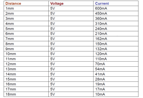
| + | Wireless charging works on the principle of Electromagnetic induction. We have used a 12V 600mA Wireless Charging Module for Wireless transfer of power to the LPC1769 board and the PCB. This module has a Transmit-receive distance of about 1-20mm. The receiver and transmitter module both have windings which help in transmitting AC voltage. The transmitter gets DC input from a 12V 1.5Amp DC adapter. This DC voltage is converted to AC for transmission purpose. On the receiver side, it converts the AC voltage received to DC 12V and gives it to the PCB and MCU through a Voltage regulator. The receiver module coil is attached to the upper board while the transmitter coil is attached a few millimetres below on the motor shaft. | ||
| + | |||
| + | <center> | ||
| + | <div><ul> | ||
| + | <li style="display: inline-block;"> [[File:CMPE244 S17 povclock wireless charger.jpg|350px|thumb|left|Wireless Power Transmitter and Receiver]] </li> | ||
| + | <li style="display: inline-block;"> [[File:CMPE244 S17 povclock wireless module statistics.PNG|480px|thumb | left|Wireless Charging Range and current]] </li> | ||
| + | </ul></div></center> | ||
| + | |||
| + | === Reed Switch and Magnet === | ||
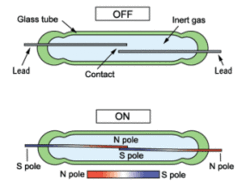
| + | Reed switch is an Electromagnetic switch which is Open-circuit by default. When a Magnetic field is brought near the switch, the two terminals of the Reed switch get short-circuited. In this project, we have used a Reed switch to give an interrupt per rotation. A strong neodymium magnetic disk is fixed at one location on the Motor. One terminal of the Reed switch is connected to 3.3V while the other terminal is connected to a GPIO pin which is configured to give an interrupt whenever it receives 3.3V. So when the motor is rotating whenever the reed switch cuts the Magnetic field, we get an interrupt. Hence we get an interrupt for every rotation. | ||
| + | <center> | ||
| + | <div><ul> | ||
| + | <li style="display: inline-block;"> [[File:CMPE244 S17 povclock reedSW.GIF|250px|thumb|left|Reed Switch Working]] </li> | ||
| + | <li style="display: inline-block;"> [[File:CMPE244 S17 ReedSwitch connection.jpg|500px|thumb | left|Reed Switch Connection]] </li> | ||
| + | </ul></div></center> | ||
| + | |||
| + | === DC Motor === | ||
| + | |||
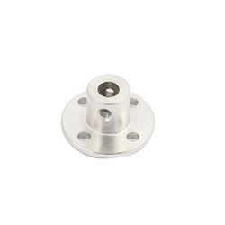
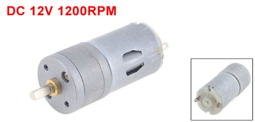
| + | We used a Uxcell 12VDC 1200RPM High Torque Electric Gearbox Gear Box Motor. We choose this motor because it has a high RPM which is necessary for having persistence of vision and it also has high torque which is capable of carrying the weight of the entire rotating setup. The motor draws power from a 9v 1.67A wall-mount Adapter. The entire rotating setup is Mounted on a motor coupler which is attached to the shaft of the motor. | ||
| + | <center> | ||
| + | <div><ul> | ||
| + | <li style="display: inline-block;"> [[File:CMPE244 S17 povclock coupler.jpg|250px|thumb|Left|Motor Shaft Coupler]] </li> | ||
| + | <li style="display: inline-block;"> [[File:CMPE244 S17 povclock DCmotor.jpg|500px|thumb|Right|High torque DC Motor]] </li> | ||
| + | </ul></div></center> | ||
| + | |||
| + | === LEDs === | ||
| + | We used Multicoloured LED's on the PCB for the main display assembly. The LED's are by default pulled up externally on the PCB and are connected to GPIO pins on the LPC1769 board. Hence we have to drive the GPIO pins LOW to switch ON the LED's and drive the GPIO pins HIGH to switch OFF the LED's. This reverse logic was done to avoid sourcing current from LPC1769 to drive the LED's as the sinking capacity of the board is greater than the sourcing capacity. | ||
=== Hardware Interface === | === Hardware Interface === | ||
| − | + | The initial idea in this project was to use slip ring and the slip ring has limited number of wires. Hence, we had planned to use SPI expander to drive the LEDs. However, once the slip ring idea was discarded and MCU was put on the PCB, we decided to use GPIO pins because of simplicity in board designing and coding. The reed switch is connected to P0.10 of the LPC1769 which is configured as GPIO input. We have used GPIO rising edge interrupt to capture the reed switch input. The LEDs are connected to port 0 (0.0 to 0.7) and port 2 (2.0 to 2.8) in active low configuration. | |
=== Software Design === | === Software Design === | ||
| − | + | [[File:CMPE244 S17 povclock initialization.jpg|1000px|thumb|center|Initialization Process]]<br> | |
| + | Time is the most critical parameter in this project. Operations are taking place in microseconds. Motor speed is uncontrolled, so exact speed of the motor is unknown and keeps varying at every rotation. To overcome this, time for each rotation is calculated dynamically using GPIO interrupt and Timer. Using this value, all the further calculations are done. | ||
| + | <br> | ||
| + | <center> | ||
| + | <div><ul> | ||
| + | <li style="display: inline-block;">[[File:CMPE244 S17 povclock Timer1 flow graph.jpg|200px|thumb|center|Timer1 Flow Graph]]</li> | ||
| + | <li style="display: inline-block;"> [[File:CMPE244 S17 povclock Timer0 flow graph.jpg |200px|thumb|center|Timer0 Flow Graph]] </li> | ||
| + | <li style="display: inline-block;"> [[File:CMPE244 S17 povclock external interrupt.jpg|200px|thumb|center|External Interrupt]] </li> | ||
| + | </ul></div></center> | ||
| + | |||
| + | |||
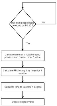
| + | TIMER1 is used to calculate time for one rotation. GPIO EINT3 interrupt is configured to trigger at rising edge. When the system completes one rotation, the GPIO pin (P0.10) connected to Reed switch triggers an interrupt and elapsed time of TIMER1 is noted. Time for angular displacement of one degree is calculated. <br> | ||
| + | |||
| + | Using this value, different LEDs (out of strip of 17) can be turned ON at precise location at any degree of rotation of the system. A separate timer, TIMER0 does the work of timekeeping, and updates seconds, minutes and hours counters. <br> | ||
| + | |||
| + | LEDs are turned ON at precise locations with the help of above two parameters at every revolution creating a POV to depict analog clock time and characters. | ||
| + | |||
| + | |||
| + | '''Algorithm Pseudocode''' | ||
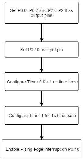
| + | * Configure GPIO pins (P0.0 to P0.7) and (P2.0 to P2.8) as output. | ||
| + | * Configure GPIO pin P0.10 as input and enable it as Rising edge-triggered interrupt. | ||
| + | * Configure TIMER0 for 1 microsecond delay and TIMER1 for 1 second delay. | ||
| + | * Start TIMER0 and TIMER1. | ||
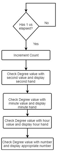
| + | * Increment Microseconds counter when TIMER0 interrupts. | ||
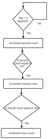
| + | * Increment Seconds counter when TIMER1 interrupts. Check if Seconds count is equal to 60. | ||
| + | * If yes, increment minutes count. Update Hours count if Minutes count is equal to 60. | ||
| + | * Wait for GPIO interrupt. | ||
| + | * When interrupt received, calculate time for one rotation by subtracting current timer-count and preceding interrupt timer-count. | ||
| + | * Calculate time for one degree traversal by dividing Rotation time by 360. | ||
| + | * Calculate time needed for angular traversal by multiplying Time needed for One-degree traversal with Seconds, Minutes and Hours count. | ||
| + | * Turn ON the required LEDs after the precise angular displacement to depict POV-based Analog-clock time and characters. | ||
| + | |||
| + | |||
| + | ''' Calculations ''' | ||
| + | * Dynamic RPM Calculation | ||
| + | Let Time for 1 rotation be t seconds<br> | ||
| + | RPM = 60/t<br> | ||
| + | Time to traverse 1 degree in 1 rotation= t/360 seconds<br> | ||
| + | eg. Time for 1 rotation is 100ms (0.1s)<br> | ||
| + | RPM= 60/0.1 = 600<br> | ||
| + | Time to traverse 1 degree in 1 rotation= 0.1/360 = 277us<br> | ||
=== Implementation === | === Implementation === | ||
| − | |||
| − | == | + | '''Hardware Implementation''' |
| − | + | * Designed and fabricated PCB to place MCU, LEDs, diode, voltage regulator and Reed Switch. | |
| − | + | * Power Supply - 9v 1.67Amp DC power adapter used to power motor and 12V 1.5 Amp DC power adapter used to power wireless module. | |
| + | * 3.3V voltage regulator used to regulate power received from Wireless Receiver. This power is used to power up MCU and PCB LED. | ||
| + | * Designed orientation of magnet for Reed switch interrupt and wireless module to supply power to MCU and LEDs. | ||
| + | |||
| + | |||
| + | '''Software Implementation''' | ||
| + | * Initialized all the system parameters which includes GPIO input/output pins, and interrupts. | ||
| + | * Initialized TIMER0/1 parameters for 1 second and 1 microsecond delay respectively. | ||
| + | * Implemented program to keep track of time in Seconds, Minutes and Hours and also in Microseconds. | ||
| + | * Designed program to manage dynamic RPM of motor and remove time related errors using GPIO interrupt rising-edge interrupt given by Reed switch. | ||
| + | * Implemented algorithm to vary all time-critical parameters for current angular traversal based on previous Rotation-time. | ||
| + | * Designed algorithm to glow different LEDs at different angular positions to depict analog-clock time and various messages using characters. | ||
| + | |||
| + | '''Character Display''' | ||
| + | * We designed characters which required 5 x 7 matrix. All characters (A to Z) where encoded and any combination of these characters can be displayed. We have 2 degree resolution, hence we can display (360 / 7*2) =~ 25 letters at the max. | ||
| + | e.g. to display 'N' we use the following logic:<br> | ||
| + | 1| 0 1 1 1 0 |1<br> | ||
| + | 1| 0 0 1 1 0 |1<br> | ||
| + | 1| 0 1 0 1 0 |1<br> | ||
| + | 1| 0 1 1 0 0 |1<br> | ||
| + | 1| 0 1 1 1 0 |1<br> | ||
| + | ____________<br> | ||
| + | 1 1 1 1 1 1 1<br> | ||
| + | 1 1 1 1 1 1 1<br> | ||
| + | 1 1 1 1 1 1 1<br> | ||
| + | |||
| + | To simplify the design, we have added 3 extra rows so as to make each column a 8-bit (char) data which we can easily store in character array <br> e.g. here N : char N[8]= {0xFF, 0xE0, 0xFD, 0xFB, 0xF7, E0, 0xFF} | ||
| + | |||
| + | The outermost columns of 1 are to keep blank lines/space between 2 characters. We use LEDs in active low configuration. Hence, here 1 means turn off LED while 0 means turn on the LED. With this method we can have two separate character display lines, one on port 0 (p0.0 to p0.7) and port 2 (2.0 to 2.7) by simply writing char value associated with characters on the corresponding ports. | ||
| + | |||
| + | For crisp display, instead of glowing the LEDs for 1 degree time (approx 277us), we are glowing the LEDs for just 125us. Also, we have written the program in such a way that it can take the time 'Tv' and text message 'Tm' at which the clock needs to display the text (characters). When the time matches with 'Tv' value, the text message 'Tm' is displayed. In this way, we have created a POV clock with visual alarm feature that displays customized text for every alarm. | ||
| + | |||
| + | == Technical Challenges & Issues == | ||
| + | We faced a lot of technical challenges and issues during the project which are highlighted below. | ||
| + | |||
| + | === Issue 1: Slip ring === | ||
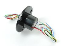
| + | Initially, the project approach was to use a slip ring to connect the wires from the MCU to the PCB and only rotate the PCB. But the slip ring had a RPM limitation of 300RPM and also the number of wires which can be connected were limited. | ||
| + | |||
| + | Solution: Hence we decided to skip the slip ring and mount the MCU on the PCB. | ||
| + | <br>[[File:CMPE244 S17 povclock slip ring.jpg|200px|thumb|center|Slip Ring]] <br> | ||
| + | |||
| + | === Issue 2: Motor start torque === | ||
| + | In the initial days of the project, we were facing an issue with the motor start torque when the load was connected. The motor used to run at good speed once it started rotating but at the start, it needed a push with the hand to start working. We needed multiple push attempts to get the motor started. Also, the motor used to work perfectly well without the load connected. | ||
| − | + | Solution: We figured out that at the start, the motor requires considerably more current at the start. To resolve the issue, we switched to a adapter which was giving a higher current and this solved the issue. | |
| − | === | + | === Issue 3: Motor RPM not constant === |
| − | + | We had planned to determine the motor RPM with final load and then build the entire logic considering that RPM (constant RPM). But we soon found out that the RPM did not have the same RPM every time we started the motor. Also, there are minute fluctuations in the RPM when motor runs which causes the clock display to drift/rotate. | |
| + | |||
| + | Solution: We decided to dynamically calculate the motor RPM during each rotation with the help of reed switch. | ||
| + | |||
| + | === Issue 4: IR Transmitter & Receiver === | ||
| + | Initially, we had ordered IR Transmitter & Receiver for the RPM calculation. But while testing, we found out that the IR transmitter was very highly directive and the receiver was not able to catch the IR signal on most rotations due to vibrations when the clock is in motion. | ||
| + | |||
| + | Solution: We decided to switch to a Magnetic Reed switch which gets triggered by a magnetic field. | ||
| + | |||
| + | === Issue 5: Magnet field orientation === | ||
| + | For the Reed switch arrangement, we were earlier placing the magnet with flat orientation. Due to this, the Reed switch was catching the magnetic field twice. Due to this, we were getting 2 interrupts near the magnet due to which the RPM calculations were going wrong. | ||
| + | |||
| + | Solution: We changed the orientation of the magnet and placed it vertically. This solved the problem and we were getting only one interrupt per rotation. | ||
| + | |||
| + | === Issue 6: Distance consideration of Wireless charger === | ||
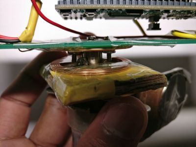
| + | The range of the wireless charging module is very less. We had to place the wireless modules very close to each other. This meant making a sophisticated mechanical arrangement where-in the Transmitter has to be mounted on the shaft(as it has to be very close to the receiver) but should not rotate with the shaft. | ||
| + | [[File:CMPE244 S17 povclock wireless charger demo.jpeg|400px|thumb|center|Wireless Charger Implementation]] <br> | ||
| + | |||
| + | === Issue 7: Weight Balancing === | ||
| + | Our PCB is designed such that one side of the PCB has more weight than the other as it is longer. The system was very unstable and vibrated a lot due to the weight imbalance. | ||
| + | |||
| + | Solution: We added counter-weight to the other side of the PCB which balanced the other arm of the PCB. This improved the stability of the system and made it easier to hold on to the module with hands and we did not need any mount. | ||
== Conclusion == | == Conclusion == | ||
| − | + | We set out with the aim of displaying an analog clock using POV and ended up taking the project a step further, by being able to display characters on it along with the clock! The project also has additional feature which can be utilised to display any user message at a precise user defined time. | |
| + | |||
| + | We faced a lot of issues- Hardware, Software and also Mechanical issues. The process of finding solutions to these issues taught us a lot of new things and improved our debugging and problem-solving skills. | ||
| + | |||
| + | Due to the critical time constraints in this project, we learned what difference a few microseconds makes in the microcontroller world. | ||
| + | |||
| + | In conclusion, it was a very good hands on experience on a time critical application. | ||
| + | |||
| + | == Future Developments == | ||
| + | We aim to wirelessly transmit the data to be displayed on the device. The data can be transmitted using an Android application running on your Smartphone through Bluetooth. So you type into the app whatever you want to be displayed and the system will display it. | ||
| + | |||
| + | == Project Demo == | ||
| + | === Project Demo Images === | ||
| + | <center> | ||
| + | <div><ul> | ||
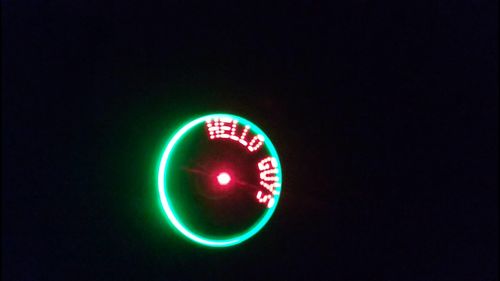
| + | <li style="display: inline-block;"> [[File:CMPE244 S17 POVClock Output1.jpg|500px|thumb|Left|Characters Display]] </li> | ||
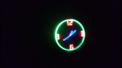
| + | <li style="display: inline-block;"> [[File:CMPE244 S17 POVClock Output2.jpg|500px|thumb|Right|Analog Clock Display]] </li> | ||
| + | </ul></div></center> | ||
=== Project Video === | === Project Video === | ||
| − | + | https://www.youtube.com/watch?v=g90dV4gD-EQ <br> | |
| + | https://youtu.be/3arQdHZnxtM | ||
=== Project Source Code === | === Project Source Code === | ||
| − | * | + | * https://drive.google.com/open?id=0Bz_W74RtLmyJM1pQNEZLZnVpdWM |
== References == | == References == | ||
=== Acknowledgement === | === Acknowledgement === | ||
| − | We would like to thank Professor Preetpal Kang for the knowledge he has given us about FreeRTOS and | + | We would like to thank Professor Preetpal Kang for the knowledge he has given us about FreeRTOS and embedded systems. |
=== References Used === | === References Used === | ||
Latest revision as of 15:35, 31 May 2017
Contents
Propeller Clock
Persistence of Vision Based Analog Clock
Abstract
Persistence of Vision (POV) refers to the optical illusion in which after image of an object seen by the eye, exists for a brief time, usually 1/10th of a second. We have used this phenomenon to create a POV clock where we display the face of an analog clock by driving one dimensional LED array (1 x 17) using precise time delays. To reduce the weight in order to achieve higher RPM necessary for POV displays, we have used wireless power supply modules to drive micro-controller and LED array which are located on the rotating arm.
Introduction
The main idea of the POV display is to flash/blink the LEDs at exact same location in each revolution. If the speed of revolution is fast enough, then the human eye cannot distinguish between two different blinks and the LEDs appear to be static and constantly glowing. Usually the motion picture frame rate is 24 frames per second and this seems to be an ideal condition for smooth POV system. However, anything above 10 updates per second can provide illusion of continuous motion.
In this project we have used 1200 RPM(no load) motor and have used 5mm bright LEDs (~10mA) which aid in creating a POV clock. Initially, the idea was to use slip ring to avoid mounting of SJOne Board on the rotating arm. However, RPM limit of 300 and limited number of wires on slip ring reduced it's feasibility. Hence, we mounted LPCXpresso LPC1769 board on the rotor and provided wireless power supply so that we can reduce the weight on the rotating arm by avoiding heavy battery. LPCXpresso LPC1769 board was chosen over SJOne board because of it's light weight and form factor which made it suitable for mounting on the rotating arm.
Instead of controlling the RPM of the motor and displaying the clock using fixed delays, we calculate and correct the time delay according to the varying RPM which in turn will compensate/nullify the effect of varying RPM on the display (moving/ dragging / stretching of the analog clock). For this, we have used reed switch.
Objectives
The main objective of this project is to implement the following:
- Determine the power consumption of the system especially the maximum current requirement so that it matches with the specified ratings of the wireless power transfer module.
- Design hardware system (PCB) which is fairly balanced and as light as possible so that it can be mounted on the rotating arm of the motor to provide balanced and stable rotation with sufficient RPM.
- Design precise time delays using timers interrupts to flash the LEDs at precise location.
- Design hardware and algorithm for compensating the change in RPM (to display a stable clock face - avoid rotation/dragging of clock face) using reed switch.
Team Members & Responsibilities
- Aakash Menon
- Designing precise timer interrupts for providing timing base for updates in each rotation.
- Aditya Choudhari
- Hardware and PCB Designing.
- Aditya Deshmukh
- DC Motor Interface.
- Reed switch/IR sensor interfacing and programming.
- Ajinkya Mandhre
- Soldering the components.
- Algorithm for displaying POV clock's hour/minute/second hand and final integration of all the codes.
- Kalki Kapoor
- Algorithm that keeps track of actual time to be displayed.
Schedule
| Week# | Start Date | End Date | Task | Status | Actual Completion Date |
|---|---|---|---|---|---|
| 1 | 03/14 | 03/20 |
|
Completed | 03/20 |
| 2 | 03/21 | 03/27 |
|
Completed | 03/27 |
| 3 | 03/28 | 04/03 |
|
Completed | 04/03 |
| 4 | 04/04 | 04/10 |
|
Completed (slip ring discarded/wireless supply added) | 04/10 |
| 5 | 04/11 | 04/17 |
|
Completed | 05/02 |
| 6 | 04/18 | 04/24 |
|
Completed | 04/24 |
| 7 | 04/25 | 05/01 |
|
Completed | 05/05 |
| 8 | 05/02 | 05/08 |
|
Completed | |
| 9 | 05/09 | 05/15 |
|
Completed | 05/15 |
| 10 | 05/16 | 05/23 |
|
Completed | 05/26 |
| 11 | 05/25 | 05/25 |
|
Completed | 05/25 |
Parts List & Cost
Below is the bill of materials required in this project.
| Item | Description | Manufacturer/Source | Quantity | Total Cost |
|---|---|---|---|---|
| LPCXpresso Board | LPCXpresso LPC1769 rev D | Embedded Artist | 1 | $23.00 |
| Wireless Charging Module | 9V 600mA (2-20mm) | robotshop.com | 2 | $19.95 |
| High Torque DC Motor | 12V 1200RPM | Uxcell - amazon.com | 1 | $15.28 |
| Motor Shaft Coupler | 5mm Rigid Flange Coupling Connector | Uxcell - amazon.com | 1 | $7.19 |
| 5mm LED multi-color | 5mm IL184 LED | Microtivity - amazon.com | 17 | $2.00 |
| Voltage Regulator | 3.3V LM1086CT 3.3 | Excess Solutions | 1 | $0.50 |
| Switch | 2x1 DIP Switch | Excess Solutions | 1 | $0.50 |
| Reed Switch | Magnetic Reed Switch | amazon.com | 1 | $2.82 |
| Magnet | GradeN52 Neodymium Magnets | CMS Magnetics - amazon.com | 1 | $3.19 |
| Power Adapter | 9V 1.67A | Excess Solutions | 1 | $5.00 |
| Power Adapter | 12V 1.5A | Excess Solutions | 1 | $2.50 |
| PCB | PCB Manufacturing | PCB4WAYS | 2 | $10.00 |
| Total Cost | $91.93 |
Design & Implementation
The initial plan in this project was to have LED strip on the rotating arm of the motor and a slip ring which would connect those LEDs with micro-controller. This way we did not have to put micro controller on the rotating arm thus we could use SJOne board and issue of battery adding weight on the rotating arm was out of question. However, all the economically viable slip rings available in the market had limitations on the RPM (< 300). With this setup, there would be five update per second; which is insufficient for persistence of vision. Hence, the idea of using slip ring was dropped.
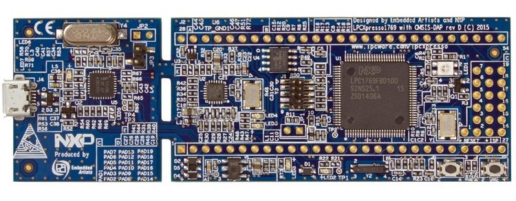
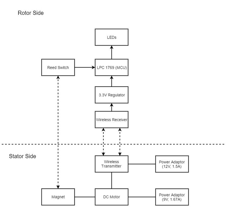
Hence, we decided to design the system with micro controller on the rotating arm. The SJOne board has weight and form factor which made it difficult to be placed on rotating arm such that it provides stable(balanced) rotations. Hence, we decided to use LPCXpresso LPC1769 which is light weight, has form factor which made it easier to put on top of the rotating arm and is based on same family of MCU 17xx (ARM Cortex M3). To further reduce weight we decided to use wireless power transmitter and receiver modules, instead of battery, to run the system.
To display a stable clock face, some method/system was required to correctly determine the RPM on real time basis. For this, we decided to use IR led and IR receiver. However, the IR LED were highly directional and even slightest movement (misalignment) of the IR receiver placed on the rotating arm gave us incorrect RPM readings. Hence, we used reed switch assembly instead. The reed switch is normally open but when it is in the magnetic field, it closes. We placed reed switch on the rotating arm and a magnet just below the rotating arm. During rotation, whenever the reed switch passed over the magnet, the micro controller pin was driven high. This was we could determine the RPM and then correctly calculate the time delay to display the clock's second, minute and hour hands.
Hardware Design
Printed Circuit Board
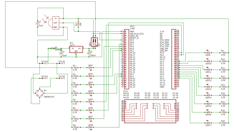
To design the PCB, we first had to decide on the length of the rotating arm. Too long arm would have led to increased load on motor while it must also be able to accommodate array of 17 LEDs. We determined that 17 5mm LEDs would require (5+1)*17 = 102mm space. Hence, we designed a 40mm x 200mm board. Our PCB design consists footprints to solder 1x17 LEDs, rectifier with voltage regulator and LPCXpresso LPC1769.
We designed the PCB using Autodesk EAGLE 8.1.1 software. Designing PCB in EAGLE is a two step process:
- Schematic Designing: In this, we need to assemble components and make the necessary electrical connections. This is just a symbolic representation of circuit. We can get the basic components and their footprint in EAGLE library. But for LPCXpresso LPC1769, we had to download specific library (.lbr) from NXP website which gave us the component object as well as required board footprint. Place the necessary components and connect them using line (wire) button.
- Board Designing: Once the schematic is ready, switch to board view where one can find a black grid with all the components clustered on one side. Select and place each component at required distance and then select tools->auto router to let EAGLE decide the best routing option. For a two layered board, select '*' option in 'top' and 'bottom' drop down list. Make sure that the components fit within the dimensions permitted under free license or else auto router wont work. Once routing is done, check for errors using ERC (Electrical Rule Check) and DRC (Design Rule Check) checks. If there are no errors then the check should return "ERC: No Error" and "DRC: No Error". We converted the unused copper layer as ground plane and added solder mask for protection.
Wireless AC Module
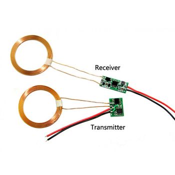
Wireless charging works on the principle of Electromagnetic induction. We have used a 12V 600mA Wireless Charging Module for Wireless transfer of power to the LPC1769 board and the PCB. This module has a Transmit-receive distance of about 1-20mm. The receiver and transmitter module both have windings which help in transmitting AC voltage. The transmitter gets DC input from a 12V 1.5Amp DC adapter. This DC voltage is converted to AC for transmission purpose. On the receiver side, it converts the AC voltage received to DC 12V and gives it to the PCB and MCU through a Voltage regulator. The receiver module coil is attached to the upper board while the transmitter coil is attached a few millimetres below on the motor shaft.
Reed Switch and Magnet
Reed switch is an Electromagnetic switch which is Open-circuit by default. When a Magnetic field is brought near the switch, the two terminals of the Reed switch get short-circuited. In this project, we have used a Reed switch to give an interrupt per rotation. A strong neodymium magnetic disk is fixed at one location on the Motor. One terminal of the Reed switch is connected to 3.3V while the other terminal is connected to a GPIO pin which is configured to give an interrupt whenever it receives 3.3V. So when the motor is rotating whenever the reed switch cuts the Magnetic field, we get an interrupt. Hence we get an interrupt for every rotation.
DC Motor
We used a Uxcell 12VDC 1200RPM High Torque Electric Gearbox Gear Box Motor. We choose this motor because it has a high RPM which is necessary for having persistence of vision and it also has high torque which is capable of carrying the weight of the entire rotating setup. The motor draws power from a 9v 1.67A wall-mount Adapter. The entire rotating setup is Mounted on a motor coupler which is attached to the shaft of the motor.
LEDs
We used Multicoloured LED's on the PCB for the main display assembly. The LED's are by default pulled up externally on the PCB and are connected to GPIO pins on the LPC1769 board. Hence we have to drive the GPIO pins LOW to switch ON the LED's and drive the GPIO pins HIGH to switch OFF the LED's. This reverse logic was done to avoid sourcing current from LPC1769 to drive the LED's as the sinking capacity of the board is greater than the sourcing capacity.
Hardware Interface
The initial idea in this project was to use slip ring and the slip ring has limited number of wires. Hence, we had planned to use SPI expander to drive the LEDs. However, once the slip ring idea was discarded and MCU was put on the PCB, we decided to use GPIO pins because of simplicity in board designing and coding. The reed switch is connected to P0.10 of the LPC1769 which is configured as GPIO input. We have used GPIO rising edge interrupt to capture the reed switch input. The LEDs are connected to port 0 (0.0 to 0.7) and port 2 (2.0 to 2.8) in active low configuration.
Software Design
Time is the most critical parameter in this project. Operations are taking place in microseconds. Motor speed is uncontrolled, so exact speed of the motor is unknown and keeps varying at every rotation. To overcome this, time for each rotation is calculated dynamically using GPIO interrupt and Timer. Using this value, all the further calculations are done.
TIMER1 is used to calculate time for one rotation. GPIO EINT3 interrupt is configured to trigger at rising edge. When the system completes one rotation, the GPIO pin (P0.10) connected to Reed switch triggers an interrupt and elapsed time of TIMER1 is noted. Time for angular displacement of one degree is calculated.
Using this value, different LEDs (out of strip of 17) can be turned ON at precise location at any degree of rotation of the system. A separate timer, TIMER0 does the work of timekeeping, and updates seconds, minutes and hours counters.
LEDs are turned ON at precise locations with the help of above two parameters at every revolution creating a POV to depict analog clock time and characters.
Algorithm Pseudocode
- Configure GPIO pins (P0.0 to P0.7) and (P2.0 to P2.8) as output.
- Configure GPIO pin P0.10 as input and enable it as Rising edge-triggered interrupt.
- Configure TIMER0 for 1 microsecond delay and TIMER1 for 1 second delay.
- Start TIMER0 and TIMER1.
- Increment Microseconds counter when TIMER0 interrupts.
- Increment Seconds counter when TIMER1 interrupts. Check if Seconds count is equal to 60.
- If yes, increment minutes count. Update Hours count if Minutes count is equal to 60.
- Wait for GPIO interrupt.
- When interrupt received, calculate time for one rotation by subtracting current timer-count and preceding interrupt timer-count.
- Calculate time for one degree traversal by dividing Rotation time by 360.
- Calculate time needed for angular traversal by multiplying Time needed for One-degree traversal with Seconds, Minutes and Hours count.
- Turn ON the required LEDs after the precise angular displacement to depict POV-based Analog-clock time and characters.
Calculations
- Dynamic RPM Calculation
Let Time for 1 rotation be t seconds
RPM = 60/t
Time to traverse 1 degree in 1 rotation= t/360 seconds
eg. Time for 1 rotation is 100ms (0.1s)
RPM= 60/0.1 = 600
Time to traverse 1 degree in 1 rotation= 0.1/360 = 277us
Implementation
Hardware Implementation
- Designed and fabricated PCB to place MCU, LEDs, diode, voltage regulator and Reed Switch.
- Power Supply - 9v 1.67Amp DC power adapter used to power motor and 12V 1.5 Amp DC power adapter used to power wireless module.
- 3.3V voltage regulator used to regulate power received from Wireless Receiver. This power is used to power up MCU and PCB LED.
- Designed orientation of magnet for Reed switch interrupt and wireless module to supply power to MCU and LEDs.
Software Implementation
- Initialized all the system parameters which includes GPIO input/output pins, and interrupts.
- Initialized TIMER0/1 parameters for 1 second and 1 microsecond delay respectively.
- Implemented program to keep track of time in Seconds, Minutes and Hours and also in Microseconds.
- Designed program to manage dynamic RPM of motor and remove time related errors using GPIO interrupt rising-edge interrupt given by Reed switch.
- Implemented algorithm to vary all time-critical parameters for current angular traversal based on previous Rotation-time.
- Designed algorithm to glow different LEDs at different angular positions to depict analog-clock time and various messages using characters.
Character Display
- We designed characters which required 5 x 7 matrix. All characters (A to Z) where encoded and any combination of these characters can be displayed. We have 2 degree resolution, hence we can display (360 / 7*2) =~ 25 letters at the max.
e.g. to display 'N' we use the following logic:
1| 0 1 1 1 0 |1
1| 0 0 1 1 0 |1
1| 0 1 0 1 0 |1
1| 0 1 1 0 0 |1
1| 0 1 1 1 0 |1
____________
1 1 1 1 1 1 1
1 1 1 1 1 1 1
1 1 1 1 1 1 1
To simplify the design, we have added 3 extra rows so as to make each column a 8-bit (char) data which we can easily store in character array
e.g. here N : char N[8]= {0xFF, 0xE0, 0xFD, 0xFB, 0xF7, E0, 0xFF}
The outermost columns of 1 are to keep blank lines/space between 2 characters. We use LEDs in active low configuration. Hence, here 1 means turn off LED while 0 means turn on the LED. With this method we can have two separate character display lines, one on port 0 (p0.0 to p0.7) and port 2 (2.0 to 2.7) by simply writing char value associated with characters on the corresponding ports.
For crisp display, instead of glowing the LEDs for 1 degree time (approx 277us), we are glowing the LEDs for just 125us. Also, we have written the program in such a way that it can take the time 'Tv' and text message 'Tm' at which the clock needs to display the text (characters). When the time matches with 'Tv' value, the text message 'Tm' is displayed. In this way, we have created a POV clock with visual alarm feature that displays customized text for every alarm.
Technical Challenges & Issues
We faced a lot of technical challenges and issues during the project which are highlighted below.
Issue 1: Slip ring
Initially, the project approach was to use a slip ring to connect the wires from the MCU to the PCB and only rotate the PCB. But the slip ring had a RPM limitation of 300RPM and also the number of wires which can be connected were limited.
Solution: Hence we decided to skip the slip ring and mount the MCU on the PCB.
Issue 2: Motor start torque
In the initial days of the project, we were facing an issue with the motor start torque when the load was connected. The motor used to run at good speed once it started rotating but at the start, it needed a push with the hand to start working. We needed multiple push attempts to get the motor started. Also, the motor used to work perfectly well without the load connected.
Solution: We figured out that at the start, the motor requires considerably more current at the start. To resolve the issue, we switched to a adapter which was giving a higher current and this solved the issue.
Issue 3: Motor RPM not constant
We had planned to determine the motor RPM with final load and then build the entire logic considering that RPM (constant RPM). But we soon found out that the RPM did not have the same RPM every time we started the motor. Also, there are minute fluctuations in the RPM when motor runs which causes the clock display to drift/rotate.
Solution: We decided to dynamically calculate the motor RPM during each rotation with the help of reed switch.
Issue 4: IR Transmitter & Receiver
Initially, we had ordered IR Transmitter & Receiver for the RPM calculation. But while testing, we found out that the IR transmitter was very highly directive and the receiver was not able to catch the IR signal on most rotations due to vibrations when the clock is in motion.
Solution: We decided to switch to a Magnetic Reed switch which gets triggered by a magnetic field.
Issue 5: Magnet field orientation
For the Reed switch arrangement, we were earlier placing the magnet with flat orientation. Due to this, the Reed switch was catching the magnetic field twice. Due to this, we were getting 2 interrupts near the magnet due to which the RPM calculations were going wrong.
Solution: We changed the orientation of the magnet and placed it vertically. This solved the problem and we were getting only one interrupt per rotation.
Issue 6: Distance consideration of Wireless charger
The range of the wireless charging module is very less. We had to place the wireless modules very close to each other. This meant making a sophisticated mechanical arrangement where-in the Transmitter has to be mounted on the shaft(as it has to be very close to the receiver) but should not rotate with the shaft.
Issue 7: Weight Balancing
Our PCB is designed such that one side of the PCB has more weight than the other as it is longer. The system was very unstable and vibrated a lot due to the weight imbalance.
Solution: We added counter-weight to the other side of the PCB which balanced the other arm of the PCB. This improved the stability of the system and made it easier to hold on to the module with hands and we did not need any mount.
Conclusion
We set out with the aim of displaying an analog clock using POV and ended up taking the project a step further, by being able to display characters on it along with the clock! The project also has additional feature which can be utilised to display any user message at a precise user defined time.
We faced a lot of issues- Hardware, Software and also Mechanical issues. The process of finding solutions to these issues taught us a lot of new things and improved our debugging and problem-solving skills.
Due to the critical time constraints in this project, we learned what difference a few microseconds makes in the microcontroller world.
In conclusion, it was a very good hands on experience on a time critical application.
Future Developments
We aim to wirelessly transmit the data to be displayed on the device. The data can be transmitted using an Android application running on your Smartphone through Bluetooth. So you type into the app whatever you want to be displayed and the system will display it.
Project Demo
Project Demo Images
Project Video
https://www.youtube.com/watch?v=g90dV4gD-EQ
https://youtu.be/3arQdHZnxtM
Project Source Code
References
Acknowledgement
We would like to thank Professor Preetpal Kang for the knowledge he has given us about FreeRTOS and embedded systems.
References Used
1. http://www.nxp.com/documents/user_manual/UM10360.pdf
2. http://people.ece.cornell.edu/land/courses/ece4760/FinalProjects/f2012/cfz4_sjh234/cfz4_sjh234/FinalProjectDocumentation.html
3. http://people.ece.cornell.edu/land/courses/ece4760/FinalProjects/f2013/js2839_yc969/js2839_yc969/js2839_yc969/index.html
