Difference between revisions of "S13: Garage Parking Aid"
(Created page with "=== Grading Criteria === <font color="green"> * How well is Software & Hardware Design described? * How well can this report be used to reproduce this project? * Code Quali...") |
(→Project Source Code) |
||
| (147 intermediate revisions by 2 users not shown) | |||
| Line 1: | Line 1: | ||
| − | === | + | == Garage Parking Aid == |
| − | |||
| − | |||
| − | |||
| − | |||
| − | |||
| − | |||
| − | |||
| − | |||
| − | |||
| − | |||
| − | + | [[File:CmpE146_S13_T3_exterior.jpg|center|frame|'''Garage Parking Aid''']] | |
== Abstract == | == Abstract == | ||
| − | This | + | |
| + | The purpose of this project is to aid when parking a car. This device will send to an Android phone the distance between the car and an obstacle. | ||
== Objectives & Introduction == | == Objectives & Introduction == | ||
| − | + | ||
| + | * Measure distance and display on computer screen | ||
| + | * Send data over bluetooth | ||
| + | * Combine bluetooth and ultrasonic | ||
| + | |||
| + | [[File:CmpE146_S13_T3_birdeye.jpg|center|frame|Bird's eye view]] | ||
=== Team Members & Responsibilities === | === Team Members & Responsibilities === | ||
| − | * | + | * Elizabeth |
| − | ** | + | ** Create UART2 driver |
| − | * | + | ** Wire peripherals |
| − | ** | + | ** Send messages with Bluetooth |
| + | * Tian | ||
| + | ** Create Android app | ||
| + | ** Assemble project into a box | ||
| + | ** Configure ultrasonic distance meter | ||
== Schedule == | == Schedule == | ||
| − | + | <table class="wikitable"> | |
| + | <th>Week Number</th> <th>Planned Items</th> <th>Actual</th> | ||
| + | |||
| + | <tr> | ||
| + | <td> <center> | ||
| + | 1 | ||
| + | </center> </td> | ||
| + | <td> | ||
| + | * Receive Bluetooth board | ||
| + | * Receive Ultrasonic board | ||
| + | * Complete Schedule | ||
| + | </td> | ||
| + | |||
| + | <td> | ||
| + | * Receive bluetooth board | ||
| + | * Receive ultrasonic board | ||
| + | * complete schedule | ||
| + | |||
| + | </td> | ||
| + | </tr> | ||
| + | |||
| + | <tr> | ||
| + | <td> <center> | ||
| + | 2 | ||
| + | </center></td> | ||
| + | <td> | ||
| + | * Transmit a signal with bluetooth | ||
| + | * Andoid app created | ||
| + | </td> | ||
| + | |||
| + | <td> | ||
| + | * bluetooth wired | ||
| + | * basic Android app created | ||
| + | |||
| + | </td> | ||
| + | </tr> | ||
| + | |||
| + | <tr> | ||
| + | <td> <center> | ||
| + | 3 | ||
| + | </center></td> | ||
| + | <td> | ||
| + | * Fix bluetooth bugs | ||
| + | * Ultrasound working properly with board | ||
| + | </td> | ||
| + | |||
| + | <td> | ||
| + | * send data over bluetooth | ||
| + | |||
| + | </td> | ||
| + | </tr> | ||
| + | |||
| + | <tr> | ||
| + | <td> <center> | ||
| + | 4 | ||
| + | </center></td> | ||
| + | <td> | ||
| + | * Connect all components | ||
| + | * Test | ||
| + | </td> | ||
| + | |||
| + | <td> | ||
| + | * Project put into casing | ||
| + | |||
| + | </td> | ||
| + | </tr> | ||
| + | |||
| + | <tr> | ||
| + | <td> <center> | ||
| + | 5 | ||
| + | </center></td> | ||
| + | <td> | ||
| + | * Working device | ||
| + | * Work on reports | ||
| + | </td> | ||
| + | |||
| + | <td> | ||
| + | * Device is working | ||
| + | * Report is being done. | ||
| + | |||
| + | </td> | ||
| + | </tr> | ||
| + | </table> | ||
== Parts List & Cost == | == Parts List & Cost == | ||
| − | + | ||
| + | {| class="wikitable" | ||
| + | |- | ||
| + | ! Parts | ||
| + | ! Cost | ||
| + | |- | ||
| + | | SJ One Board | ||
| + | | $65 | ||
| + | |- | ||
| + | | Bluetooth | ||
| + | | $0 | ||
| + | |- | ||
| + | | 2.4 GHz Antenna | ||
| + | | $5 | ||
| + | |- | ||
| + | | Ultrasonic transmitter and receiver | ||
| + | | $10 | ||
| + | |- | ||
| + | | Blackbox | ||
| + | | $0 | ||
| + | |- | ||
| + | | Wire | ||
| + | | $10 | ||
| + | |- | ||
| + | | Batteries | ||
| + | | $7 | ||
| + | |- | ||
| + | ! Total: | ||
| + | ! $97 | ||
| + | |} | ||
== Design & Implementation == | == Design & Implementation == | ||
| − | + | ||
=== Hardware Design === | === Hardware Design === | ||
| − | + | ||
| + | The following hardware components are all that we used for this project. The LPC1758 Processor on the SJSU_ONE Development Board, which is powered by the battery pack, controls everything through the board. It activates the ultrasonic module, gets the time reading from it, computes the readings into distance and then transfer the data to bluetooth module, then the bluetooth module will send the received data to the Android Application on a paired bluetooth Android Device through the 2.4Ghz Antenna. | ||
| + | |||
| + | [[File:CmpE146_S13_T3_LPC1758.jpg|center|frame|SJSU_ONE Development Board]] | ||
| + | |||
| + | [[File:CmpE146_S13_T3_bluetooth2.jpg|center|frame|Bluetooth]] | ||
| + | [[File:CmpE146_S13_T3_Bluetooth_Pin.jpg|center|frame|Bluetooth Pin Assignment]] | ||
| + | |||
| + | [[File:CmpE146_S13_T3_ultrasonic2.jpg|center|frame|Ultrasonic]] | ||
| + | [[File:CmpE146_S13_T3_Ultra_Pin.jpg|center|frame|Ultrasonic Pin Assignment]] | ||
| + | |||
| + | [[File:CmpE146_S13_T3_antenna.jpg|center|frame|2.4 GHz Antenna]] | ||
| + | |||
| + | [[File:CmpE146_S13_T3_BatteryPackSmall.jpg|center|frame|4 x AA Battery Pack]] | ||
=== Hardware Interface === | === Hardware Interface === | ||
| − | + | ||
| + | [[File:CmpE146_S13_T3_interior.jpg|center|frame|Interior Connection]] | ||
| + | |||
| + | [[File:CmpE146 S13 T3 wiring2.jpg|center|frame|Schematic]] | ||
| + | |||
| + | |||
| + | |||
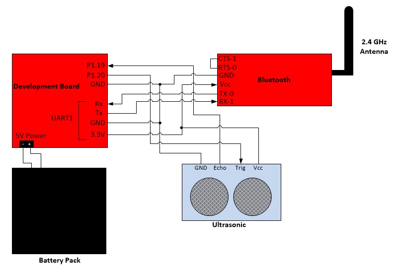
| + | Hardware Communication: The development board is connected to the bluetooth chip and ultrasonic receiver/transmitter. The bluetooth receives data through pin RX-1, which is TX on the processor's pin, and transmits the data over bluetooth. The ultrasonic receives a trigger signal through the pin Trigger then sends an ultrasonic pulse. When the Echo pin is read back, it will send a high signal to the board for the time it took the sonic wave to be sent then received. The battery gives 5V power to development board and ultrasonic. | ||
| + | |||
| + | The Bluetooth device is connected to UART1 and the ultrasonic device is connected to GPIO. To communicate with the Bluetooth, the processor sends and receives data via UART1 TX/RX Pins which are connected to the RX/TX Pins on the bluetooth. RTS pin is tied to CTS pin, which means bluetooth is always clear to send data is ready to send. To communicate with the ultrasonic, the processor sends and receives data through the board's pins P1.20 and P1.19, which are programmed to be output and input ports that directly connect to the Trig and Echo. | ||
| + | |||
| + | Another option to capture the time of the ultrasonic's pulse, is to program the GPIO pins to be PWM and capture. The PWM pin will output a pulse to the ultrasonic and the ultrasonic will send an ultrasonic pulse. When it receives an echo of the pulse, it will send a pulse to the capture pin. When the capture pin receives a change in voltage, it will store the time into a designated register. The capture pin can be programmed to capture on rising or falling edge. | ||
=== Software Design === | === Software Design === | ||
| − | + | ||
| + | [[File:CmpE146_S13_T3_software.jpg|center|frame|Software Design]] | ||
| + | |||
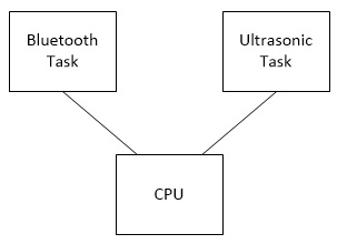
| + | For Software Design on the board side, we have two tasks dedicated for two components: bluetooth_task and ultrasonic_task. We use queue for data transfer between two tasks. | ||
| + | |||
| + | '''Ultrasonic_task''' | ||
| + | |||
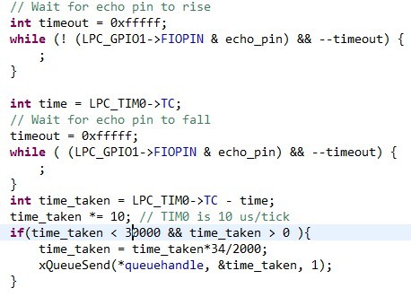
| + | This task takes a queue handle pointer and stores it to its private local variable. Two pins are initialized: Trigger as output, Echo as input. As the task begins to run, the Trigger Pin is set high for 20us then is cleared. This will activate ultrasonic module to send 8 pulses of sound wave. The board will monitor the Echo Pin and once the Echo Pin goes high it will start the timer. When the pin falls back to low it will stop the timer. The time the echo pin is high it is the time for the soundwave to be send and received. To calculate the distance, use the time measured and multiple by the speed of sound, then divided by two, ( Distance = ((Duration of high level)*(Sonic :340m/s))/2 ) After that, we use xQueueSend function to immediately send this distance value to the queue handler, and end this run. This task is designed to run every 2 sec. | ||
| + | |||
| + | [[File:CmpE146_S13_T3_Ultra_Code.jpg|center|frame|ultrasonic_task]] | ||
| + | |||
| + | '''Bluetooth_task''' | ||
| + | |||
| + | This task also takes a queue handle pointer and stores it to a private local variable. In addition, this task has another private variable that will get the instance of Uart2 Class, which controls ports connected to our bluetooth module. The third variable called distance and will store the distance received from the queue. The board has a mislabel Uart1 and is supposed to be Uart2. | ||
| + | |||
| + | [[File:CmpE146_S13_T3_Bluetooth_Local.jpg|center|frame|bluetooth_task local variable]] | ||
| + | |||
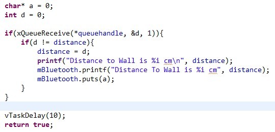
| + | The task first initializes the bluetooth module, then runs in a loop, checking if anything is on the queue, if yes, it immediately receives it, if it is different from the stored value in distance from previous run, store it to local variable, distance, and output a message string containing the distance to the paired android device. | ||
| + | |||
| + | [[File:CmpE146_S13_T3_Bluetooth_Code.jpg|center|frame|bluetooth_task]] | ||
| + | |||
| + | '''Main Function''' | ||
| + | |||
| + | The main function is really simple, it first creates a queue handle with xQueueCreate, then calls both tasks and pass the address of this handle to them. | ||
| + | |||
| + | [[File:CmpE146_S13_T3_Main_Code.jpg|center|frame|main function]] | ||
| + | |||
| + | '''Android App''' | ||
| + | |||
| + | For the Android App, Our design is really simple: the app is going to check if bluetooth on your Android phone is on, if not, it will prompt the user to turn it on; then it is going to start continuously receiving string that is sent from the board via bluetooth, and then parse the string, check for end of line '/r/n', and then display the string at the center of the screen in TextView field, saying how far is your car is to the wall in cm. We pre-loaded the MAC address of the bluetooth module into the app, so we don't have to manually connect to it everytime. But this requires that the bluetooth module is paired with your phone already, and bluetooth permission is granted to the app. | ||
| + | |||
| + | [[File:CmpE146_S13_T3_Request_bt.jpg|center|frame|main function]] | ||
| + | |||
| + | [[File:CmpE146_S13_T3_Display_distance.jpg|center|frame|main function]] | ||
=== Implementation === | === Implementation === | ||
| − | + | ||
| + | |||
| + | [[File:CmpE146_S13_T3_flowchart.jpg|center|frame|Flowchart]] | ||
| + | |||
| + | The above flow chart is a clear view of the whole process of our project. | ||
| + | |||
| + | '''Get reading from Ultrasonic''' | ||
| + | |||
| + | 1. Set Trigger Pin<br> | ||
| + | 2. Clear Trigger Pin<br> | ||
| + | 3. Wait for Echo Pin to go High<br> | ||
| + | 4. Measure the time duration that Echo Pin stays High<br> | ||
| + | 5. Echo Pin falls back to Low<br> | ||
| + | 6. Calculate distance: Distance = ((Duration of high level)*(Sonic :340m/s))/2<br> | ||
| + | <br> | ||
| + | <br> | ||
| + | '''Send data through bluetooth''' | ||
| + | |||
| + | 1. Receive data from queue and store it to an int temp variable<br> | ||
| + | 2. Compare temp with local private variable distance<br> | ||
| + | 3. If not equal, update temp to distance and send it through bluetooth<br> | ||
| + | 4. If equal, skip this data, and start new run and wait for the next available data from queue<br> | ||
| + | <br> | ||
| + | <br> | ||
| + | |||
| + | '''Android App''' | ||
| + | |||
| + | 1. Add permission to AndroidManifect.xml:<br> | ||
| + | <uses-permission android:name="android.permission.BLUETOOTH_ADMIN" /><br> | ||
| + | <uses-permission android:name="android.permission.BLUETOOTH" /><br> | ||
| + | 2. Set up GUI, add TextView.<br> | ||
| + | 3. Check the state of Bluetooth adapter, if not Enable, request to enable.<br> | ||
| + | 4. Get the remote device, which is the bluetooth module, using its MAC address, and create a socket for communication using the SPP UUID: "00001101-0000-1000-8000-00805F9B34FB" and connect. Then disable Discovery Mode<br> | ||
| + | 5. Create a Thread for receiving input stream, pass the message string to the string handle, parse the string and display in the TextView. | ||
== Testing & Technical Challenges == | == Testing & Technical Challenges == | ||
| − | |||
| − | |||
| − | + | One major problem during testing, is whenever we point the ultrasonic module towards an object at a bad angle, where the exposed surface of the object is not sufficient, the ultrasonic reading gets stuck and the Echo Pin will keep staying Low. The solution to this problem is to add a timeout inside Ultrasonic_task to break out of the loop after reaching the timeout limit and check the timer to see if the time measured is greater than 0 and less than the time of maximum distance it could support. If the condition returns false, ignore this value and skip the queue process, and re-activated the trigger. | |
| − | === | + | == Conclusion == |
| − | |||
| − | + | From this project, we gained a better understanding on how FreeRTOS, Uart, Bluetooth communication works. We also learned how to build a simple Android Application associated with Bluetooth. Our project is pretty simple, but this is my (TIAN) first hardware/software hybrid project, where we had to start from the beginning, design, build and code, and finally test. We were stuck several times throughout the project, but with Preet's help, we came through. However, we did not do a good job managing the time, and in the end we were not able to implement some of of features that we wanted in the first place, such as sound warning at a close distance or radar view of the distance. But It is a good experience, and a reference to both of us in our future projects. | |
| − | |||
=== Project Video === | === Project Video === | ||
| − | + | Initial Demo: | |
| + | https://www.youtube.com/watch?v=Neq6_BrYMEc&feature=youtu.be | ||
=== Project Source Code === | === Project Source Code === | ||
| − | + | * [https://sourceforge.net/projects/sjsus13/files/ Project source code is available at SourceForge] | |
== References == | == References == | ||
=== Acknowledgement === | === Acknowledgement === | ||
| − | + | * Preet Kang | |
| + | * Dr. Haluk Ozemek | ||
=== References Used === | === References Used === | ||
| − | + | ||
| + | * https://www.sparkfun.com/products/158 | ||
| + | * https://s3-ap-northeast-1.amazonaws.com/sain-amzn/20/20-019-100/HC-SR04.rar | ||
| + | * http://wiring.org.co/learning/tutorials/bluetooth/ | ||
| + | * http://www.lynxmotion.com/images/html/build117.htm | ||
=== Appendix === | === Appendix === | ||
| − | + | ||
| + | * http://www.micropik.com/PDF/HCSR04.pdf | ||
| + | * https://www.sparkfun.com/datasheets/Wireless/Bluetooth/rn-bluetooth-um.pdf | ||
| + | * https://www.sparkfun.com/datasheets/RF/BlueSMiRF-RPSMA-Schematic.pdf | ||
| + | * https://www.sparkfun.com/datasheets/RF/BlueSMiRF_v1.pdf | ||
Latest revision as of 21:21, 23 May 2013
Contents
Garage Parking Aid
Abstract
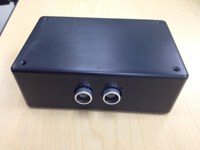
The purpose of this project is to aid when parking a car. This device will send to an Android phone the distance between the car and an obstacle.
Objectives & Introduction
- Measure distance and display on computer screen
- Send data over bluetooth
- Combine bluetooth and ultrasonic
Team Members & Responsibilities
- Elizabeth
- Create UART2 driver
- Wire peripherals
- Send messages with Bluetooth
- Tian
- Create Android app
- Assemble project into a box
- Configure ultrasonic distance meter
Schedule
| Week Number | Planned Items | Actual |
|---|---|---|
| 1 |
|
|
| 2 |
|
|
| 3 |
|
|
| 4 |
|
|
| 5 |
|
|
Parts List & Cost
| Parts | Cost |
|---|---|
| SJ One Board | $65 |
| Bluetooth | $0 |
| 2.4 GHz Antenna | $5 |
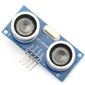
| Ultrasonic transmitter and receiver | $10 |
| Blackbox | $0 |
| Wire | $10 |
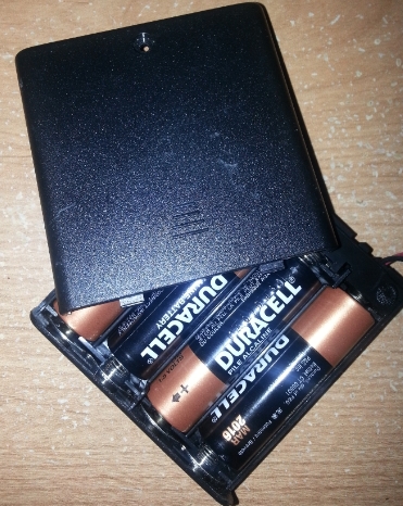
| Batteries | $7 |
| Total: | $97 |
Design & Implementation
Hardware Design
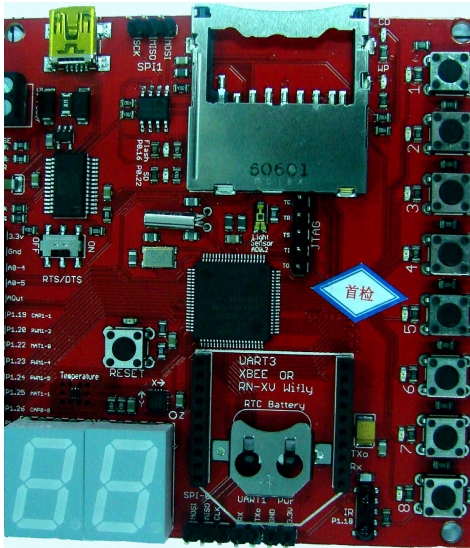
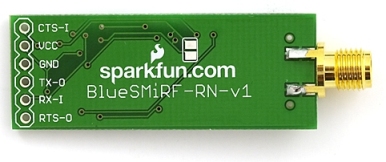
The following hardware components are all that we used for this project. The LPC1758 Processor on the SJSU_ONE Development Board, which is powered by the battery pack, controls everything through the board. It activates the ultrasonic module, gets the time reading from it, computes the readings into distance and then transfer the data to bluetooth module, then the bluetooth module will send the received data to the Android Application on a paired bluetooth Android Device through the 2.4Ghz Antenna.
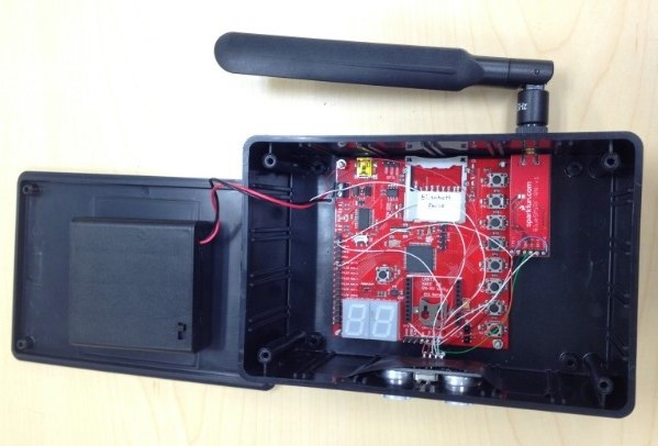
Hardware Interface
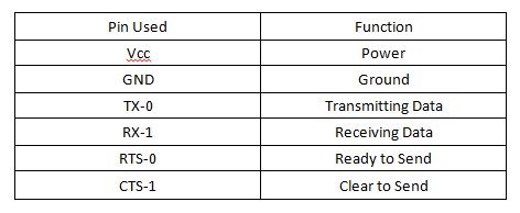
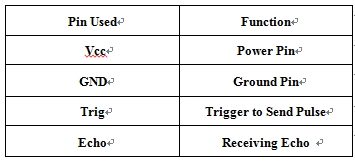
Hardware Communication: The development board is connected to the bluetooth chip and ultrasonic receiver/transmitter. The bluetooth receives data through pin RX-1, which is TX on the processor's pin, and transmits the data over bluetooth. The ultrasonic receives a trigger signal through the pin Trigger then sends an ultrasonic pulse. When the Echo pin is read back, it will send a high signal to the board for the time it took the sonic wave to be sent then received. The battery gives 5V power to development board and ultrasonic.
The Bluetooth device is connected to UART1 and the ultrasonic device is connected to GPIO. To communicate with the Bluetooth, the processor sends and receives data via UART1 TX/RX Pins which are connected to the RX/TX Pins on the bluetooth. RTS pin is tied to CTS pin, which means bluetooth is always clear to send data is ready to send. To communicate with the ultrasonic, the processor sends and receives data through the board's pins P1.20 and P1.19, which are programmed to be output and input ports that directly connect to the Trig and Echo.
Another option to capture the time of the ultrasonic's pulse, is to program the GPIO pins to be PWM and capture. The PWM pin will output a pulse to the ultrasonic and the ultrasonic will send an ultrasonic pulse. When it receives an echo of the pulse, it will send a pulse to the capture pin. When the capture pin receives a change in voltage, it will store the time into a designated register. The capture pin can be programmed to capture on rising or falling edge.
Software Design
For Software Design on the board side, we have two tasks dedicated for two components: bluetooth_task and ultrasonic_task. We use queue for data transfer between two tasks.
Ultrasonic_task
This task takes a queue handle pointer and stores it to its private local variable. Two pins are initialized: Trigger as output, Echo as input. As the task begins to run, the Trigger Pin is set high for 20us then is cleared. This will activate ultrasonic module to send 8 pulses of sound wave. The board will monitor the Echo Pin and once the Echo Pin goes high it will start the timer. When the pin falls back to low it will stop the timer. The time the echo pin is high it is the time for the soundwave to be send and received. To calculate the distance, use the time measured and multiple by the speed of sound, then divided by two, ( Distance = ((Duration of high level)*(Sonic :340m/s))/2 ) After that, we use xQueueSend function to immediately send this distance value to the queue handler, and end this run. This task is designed to run every 2 sec.
Bluetooth_task
This task also takes a queue handle pointer and stores it to a private local variable. In addition, this task has another private variable that will get the instance of Uart2 Class, which controls ports connected to our bluetooth module. The third variable called distance and will store the distance received from the queue. The board has a mislabel Uart1 and is supposed to be Uart2.
The task first initializes the bluetooth module, then runs in a loop, checking if anything is on the queue, if yes, it immediately receives it, if it is different from the stored value in distance from previous run, store it to local variable, distance, and output a message string containing the distance to the paired android device.
Main Function
The main function is really simple, it first creates a queue handle with xQueueCreate, then calls both tasks and pass the address of this handle to them.
Android App
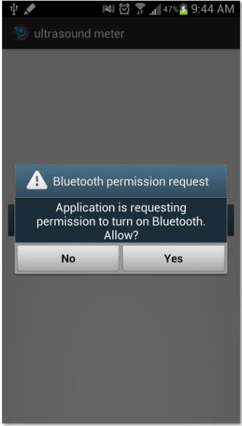
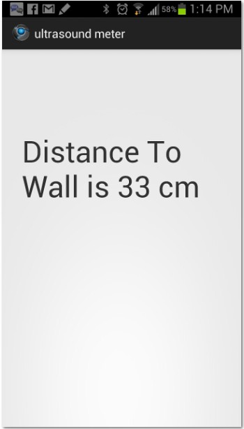
For the Android App, Our design is really simple: the app is going to check if bluetooth on your Android phone is on, if not, it will prompt the user to turn it on; then it is going to start continuously receiving string that is sent from the board via bluetooth, and then parse the string, check for end of line '/r/n', and then display the string at the center of the screen in TextView field, saying how far is your car is to the wall in cm. We pre-loaded the MAC address of the bluetooth module into the app, so we don't have to manually connect to it everytime. But this requires that the bluetooth module is paired with your phone already, and bluetooth permission is granted to the app.
Implementation
The above flow chart is a clear view of the whole process of our project.
Get reading from Ultrasonic
1. Set Trigger Pin
2. Clear Trigger Pin
3. Wait for Echo Pin to go High
4. Measure the time duration that Echo Pin stays High
5. Echo Pin falls back to Low
6. Calculate distance: Distance = ((Duration of high level)*(Sonic :340m/s))/2
Send data through bluetooth
1. Receive data from queue and store it to an int temp variable
2. Compare temp with local private variable distance
3. If not equal, update temp to distance and send it through bluetooth
4. If equal, skip this data, and start new run and wait for the next available data from queue
Android App
1. Add permission to AndroidManifect.xml:
   <uses-permission android:name="android.permission.BLUETOOTH_ADMIN" />

   <uses-permission android:name="android.permission.BLUETOOTH" />
2. Set up GUI, add TextView.
3. Check the state of Bluetooth adapter, if not Enable, request to enable.
4. Get the remote device, which is the bluetooth module, using its MAC address, and create a socket for communication using the SPP UUID: "00001101-0000-1000-8000-00805F9B34FB" and connect. Then disable Discovery Mode
5. Create a Thread for receiving input stream, pass the message string to the string handle, parse the string and display in the TextView.
Testing & Technical Challenges
One major problem during testing, is whenever we point the ultrasonic module towards an object at a bad angle, where the exposed surface of the object is not sufficient, the ultrasonic reading gets stuck and the Echo Pin will keep staying Low. The solution to this problem is to add a timeout inside Ultrasonic_task to break out of the loop after reaching the timeout limit and check the timer to see if the time measured is greater than 0 and less than the time of maximum distance it could support. If the condition returns false, ignore this value and skip the queue process, and re-activated the trigger.
Conclusion
From this project, we gained a better understanding on how FreeRTOS, Uart, Bluetooth communication works. We also learned how to build a simple Android Application associated with Bluetooth. Our project is pretty simple, but this is my (TIAN) first hardware/software hybrid project, where we had to start from the beginning, design, build and code, and finally test. We were stuck several times throughout the project, but with Preet's help, we came through. However, we did not do a good job managing the time, and in the end we were not able to implement some of of features that we wanted in the first place, such as sound warning at a close distance or radar view of the distance. But It is a good experience, and a reference to both of us in our future projects.
Project Video
Initial Demo: https://www.youtube.com/watch?v=Neq6_BrYMEc&feature=youtu.be
Project Source Code
References
Acknowledgement
- Preet Kang
- Dr. Haluk Ozemek
References Used
- https://www.sparkfun.com/products/158
- https://s3-ap-northeast-1.amazonaws.com/sain-amzn/20/20-019-100/HC-SR04.rar
- http://wiring.org.co/learning/tutorials/bluetooth/
- http://www.lynxmotion.com/images/html/build117.htm
