Difference between revisions of "F16: Thunderbolt"
Proj user14 (talk | contribs) (→Track Progress in KanBan) |
Proj user11 (talk | contribs) (→Team members and Responsibilities) |
||
| (568 intermediate revisions by 2 users not shown) | |||
| Line 4: | Line 4: | ||
== Abstract == | == Abstract == | ||
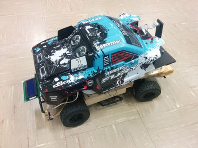
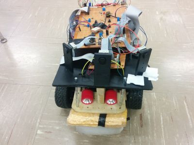
| − | + | With the autonomous industry reaching its peak of innovation, this project is another example where modern technology converges to give us something amazing. We have built a prototype of a self driving car - Thunderbolt. Imagine getting around places wherever one wants to go with the push of a button on the Android app - without the need for a person at the wheel. We have built a car prototype with fully self-driving technology that will handle all the driving. It is GPS controlled that will take its destination from the user on the Android phone and drive itself to that destination. Our car has sensors to detect the obstacles in its way. Auto adjusting speed, light sensor based headlights, automatic backlights are among some other cool features of this car.<br><br> | |
| + | [[File:CmpE243 F16 Thunderbolt Car.jpg|left|400px|thumb|Thunderbolt Car - Side View]] | ||
| + | [[File:CmpE243_F16_Thunderbolt_Car_top.jpg|right|400px|thumb|Thunderbolt Car Design]] | ||
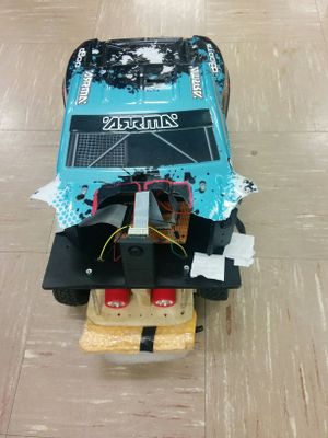
| + | [[File:CmpE243 F16 Thunderbolt Car front.jpg|center|300px|thumb|Thunderbolt Car - Front View]] | ||
== Objectives & Introduction == | == Objectives & Introduction == | ||
| − | + | The aim of this project is to design a self-driving car which can navigate its way to the destination avoiding any obstacles in its way. | |
| + | We have used five controllers for this purpose which would communicate with each other over CAN (Control Area Network) Bus. These five controllers form five modules of the project and are interfaced to different peripherals depending upon their functionality. | ||
| + | The Sensor Module interfaced with Maxbotics sensors helps sense any obstacles in between the car's path. Four sensors are used - left, right, front and back. | ||
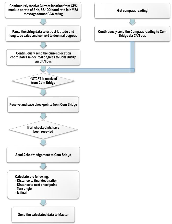
| + | The GPS module gives current location of the car and the direction for reaching its destination. | ||
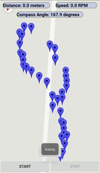
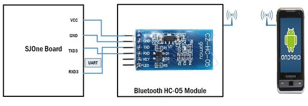
| + | The communication bridge is interfaced to an Android device over Bluetooth to perform various user related tasks like giving the final destination, starting the car, resetting the boards etc. | ||
| + | The motor module actually drives the mechanical aspects of the car such as the Servo and DC motor. A RPM sensor is used to monitor the current speed of the car and an algorithm helps maintain the car at constant speed. | ||
| + | The Master module governs these modules and is at the heart of the software engine of this car. | ||
| − | == Schedule == | + | == Team Schedule == |
| + | |||
| + | ''' Color Legends :''' | ||
| + | * <font color="black"> Common to all modules | ||
| + | * <font color="clouds"> Master Controller | ||
| + | * <font color="green"> Motor Controller | ||
| + | * <font color="red"> Sensor Controller | ||
| + | * <font color="blue"> Geographical Controller | ||
| + | * <font color="carrot"> Communication Bridge | ||
{| class="wikitable" | {| class="wikitable" | ||
| Line 18: | Line 35: | ||
! scope="col"| Task | ! scope="col"| Task | ||
! scope="col"| Status | ! scope="col"| Status | ||
| − | ! scope="col"| | + | ! scope="col"| Problems/Delays if any |
|- | |- | ||
! scope="row"| 1 | ! scope="row"| 1 | ||
| 09/14/2016 | | 09/14/2016 | ||
| 09/20/2016 | | 09/20/2016 | ||
| − | | Read previous reports | + | | |
| + | * Read previous reports to understand the working of the entire project | ||
| + | * Individual module distribution | ||
| Completed | | Completed | ||
| | | | ||
| Line 30: | Line 49: | ||
| 09/21/2016 | | 09/21/2016 | ||
| 09/27/2016 | | 09/27/2016 | ||
| − | | Set up | + | | |
| + | * Set up Git | ||
| + | * Create project report template on Wiki | ||
| + | * <font color="green"> Understanding the motor and PWM concept | ||
| Completed | | Completed | ||
| | | | ||
| Line 37: | Line 59: | ||
| 09/28/2016 | | 09/28/2016 | ||
| 10/04/2016 | | 10/04/2016 | ||
| − | |||
| − | |||
| | | | ||
| − | |- | + | * Study previous reports to decide on components to be ordered and to get an idea about the flow |
| + | * Order the components | ||
| + | * <font color="green"> Testing Servo and DC motor using RC Transmitter and Receiver | ||
| + | * <font color="carrot"> Development of basic android app for one directional Bluetooth communication | ||
| + | | Completed | ||
| + | | | ||
| + | |- | ||
! scope="row"| 4 | ! scope="row"| 4 | ||
| 10/05/2016 | | 10/05/2016 | ||
| + | | 10/11/2016 | ||
| + | | | ||
| + | * Follow-up on the ordered parts and Order the remaining components | ||
| + | * <font color="carrot"> Development of basic android app for plotting Google Map route between two points | ||
| + | * <font color="carrot"> Testing of Bluetooth Module with SJ-One Board using available Bluetooth app on Android app store | ||
| + | | Completed | ||
| + | | | ||
| + | |- | ||
| + | ! scope="row"| 5 | ||
| + | | 10/12/2016 | ||
| + | | 10/18/2016 | ||
| + | | | ||
| + | * Follow-up on the ordered parts | ||
| + | * Create branches in Git | ||
| + | * <font color="clouds"> Decide/Develop the CAN message ID and node address for all controllers | ||
| + | * <font color="green"> Testing and interfacing of servo and DC motor with SJOne Board | ||
| + | * <font color="red"> Sensor Data Sheet Review with team | ||
| + | | Completed | ||
| + | | | ||
| + | |- | ||
| + | ! scope="row"| 6 | ||
| + | | 10/19/2016 | ||
| 10/25/2016 | | 10/25/2016 | ||
| − | | | + | | |
| − | | | + | * Follow-up on the ordered parts |
| + | * Design the CAN message ID and node address for all controllers based on the priority level | ||
| + | * Design the DBC file consisting of the signals from all the modules | ||
| + | * <font color="clouds"> Integrate the Bluetooth module with the Master controller over CAN bus | ||
| + | * <font color="green"> Understanding the RPM sensor interfacing | ||
| + | * <font color="red"> Test the Individual sensors to get accurate measurements according to data sheet | ||
| + | * <font color="red"> Determine pins and architecture of board for sensor controller | ||
| + | * <font color="blue"> Interface the compass module to SJOne board using I2C communication | ||
| + | * <font color="carrot"> Bi-directional communication between SJ-ONE Board and Android App | ||
| + | | Completed | ||
| | | | ||
|- | |- | ||
| − | ! scope="row"| | + | ! scope="row"| 7 |
| 10/26/2016 | | 10/26/2016 | ||
| 11/01/2016 | | 11/01/2016 | ||
| − | |||
| | | | ||
| + | * <font color="clouds"> Interface the Motor module with the Master controller over CAN bus | ||
| + | * <font color="green"> Design a power circuit on RC car with motors interfaced to SJOne board | ||
| + | * <font color="red"> Develop entire board algorithm for all sensors | ||
| + | * <font color="blue"> Develop the algorithms for distance and turn angle calculation | ||
| + | * <font color="blue"> Interfacing of GEO controller with Master | ||
| + | * <font color="carrot"> Interface Android and Bluetooth module with CAN | ||
| + | | Completed | ||
| + | | | ||
| + | |- | ||
| + | ! scope="row"| 8 | ||
| + | | 11/02/2016 | ||
| + | | 11/08/2016 | ||
| + | | | ||
| + | * <font color="clouds"> Design the algorithm for navigation and obstacle avoidance in Master controller | ||
| + | * <font color="clouds"> Interface the sensor controllers with the Master controller over CAN bus | ||
| + | * <font color="clouds"> Interfacing the Master controller with GPS module | ||
| + | * <font color="green"> Establishing reliable CAN communication for motors with master controller | ||
| + | * <font color="green"> Interfacing of sensors with motors and testing obstacle avoidance | ||
| + | * <font color="red"> Mount all ultrasonic sensors on car and test it | ||
| + | * <font color="red"> Start implementation of CAN bus by testing sending and receiving of messages | ||
| + | * <font color="blue"> Calibrate the compass module and testing | ||
| + | | Completed | ||
| + | | | ||
| + | |- | ||
| + | ! scope="row"| 9 | ||
| + | | 11/09/2016 | ||
| + | | 11/15/2016 | ||
| + | | | ||
| + | * <font color="clouds"> Designing of the kill switch | ||
| + | * <font color="green"> Integrating it with the master controller, testing and debugging | ||
| + | * <font color="red"> Complete implementation of the sensor controller with the Master controller over CAN bus | ||
| + | * <font color="red"> Fine-tune algorithms for sensor | ||
| + | * <font color="carrot"> Interfacing with GPS module using CAN bus for receiving current location | ||
| + | * <font color="blue"> Interface GPS module to SJOne board using UART communication | ||
| + | * <font color="blue"> Calibrating the GPS and testing | ||
| + | | Completed | ||
| + | | | ||
| + | |- | ||
| + | ! scope="row"| 10 | ||
| + | | 11/16/2016 | ||
| + | | 11/22/2016 | ||
| + | | | ||
| + | * <font color="clouds"> Testing the Master module with all controllers interfaced | ||
| + | * <font color="green"> LCD module interfacing and adding extra features. | ||
| + | * <font color="red"> Test the implementation for multiple sensors and debugging the issue | ||
| + | * <font color="red"> Decide upon additional I/O such as lights | ||
| + | * <font color="blue"> Integrating of GPS and compass module | ||
| + | * <font color="blue"> Interfacing of GEO controller with Android | ||
| + | * <font color="carrot"> Integrating com_bridge with entire system | ||
| + | | Completed | ||
| + | | | ||
| + | |- | ||
| + | ! scope="row"| 11 | ||
| + | | 11/23/2016 | ||
| + | | 11/29/2016 | ||
| | | | ||
| + | * <font color="clouds"> Take care of modifications and shortcomings if any | ||
| + | * <font color="red"> Optimize the code and testing for stability and report | ||
| + | * <font color="blue"> Interfacing of GEO controller with LCD | ||
| + | * <font color="blue"> Unit Testing of GEO controller and bug fixes and re-calibrate if needed. | ||
| + | * <font color="carrot"> Testing and bug fixes | ||
| + | | Completed | ||
| + | | | ||
|- | |- | ||
| − | ! scope="row"| | + | ! scope="row"| 12 |
| − | | 11/ | + | | 11/30/2016 |
| − | | 12/ | + | | 12/06/2016 |
| − | |||
| | | | ||
| + | * <font color="clouds"> Improvise the communication on CAN bus | ||
| + | * <font color="red"> Testing and debugging | ||
| + | * <font color="carrot"> Android App GUI enhancements and bug fixes | ||
| + | | Completed | ||
| | | | ||
|- | |- | ||
| − | ! scope="row"| | + | ! scope="row"| 13 |
| − | | 12/ | + | | 12/07/2016 |
| − | | 12/ | + | | 12/13/2016 |
| − | |||
| | | | ||
| + | * Final testing of Self-Driving Car | ||
| + | | Completed | ||
| | | | ||
|} | |} | ||
== Team members and Responsibilities == | == Team members and Responsibilities == | ||
| − | * Master | + | |
| − | ** | + | <font color = "black"> |
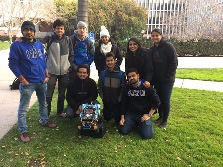
| − | ** | + | [[File:CmpE243 F16 Team thunderbolt.jpg|right|450px|thumb|Team Thunderbolt]] |
| − | + | * Master Module | |
| − | * Motor | + | **[https://www.linkedin.com/in/abhishek-singh21 Abhishek Singh]<br> |
| + | **[https://www.linkedin.com/in/saurabh-deshmukh0911 Saurabh Ravindra Deshmukh]<br> | ||
| + | * Motor Module | ||
** Krishank Mehta | ** Krishank Mehta | ||
| − | ** | + | ** [https://www.linkedin.com/in/neha-biradar-59a538103 Neha Biradar]<br> |
| − | ** Saurabh Ravindra Deshmukh | + | ** [https://www.linkedin.com/in/saurabh-deshmukh0911 Saurabh Ravindra Deshmukh]<br> |
* GPS/Compass Module | * GPS/Compass Module | ||
| − | ** Samiksha Ambekar | + | ** [https://www.linkedin.com/in/samiksha-ambekar Samiksha Ambekar]<br> |
| − | ** | + | ** [https://www.linkedin.com/in/virginia-allita-menezes Virginia Menezes]<br> |
| − | + | * Sensors Module | |
| − | |||
| − | * Sensors | ||
** Arthur Nguyen | ** Arthur Nguyen | ||
| − | ** Rajeev Sawant | + | ** [https://www.linkedin.com/in/rajeev-sawant-096561bb/ Rajeev Sawant]<br> |
| − | + | * Communication Bridge Module | |
| − | + | ** [https://www.linkedin.com/in/nikhil-namjoshi-47636191/ Nikhil Namjoshi]<br> | |
| − | + | <br><br> | |
| − | ** Nikhil Namjoshi | ||
| − | |||
| − | |||
| − | |||
== Parts List & Cost == | == Parts List & Cost == | ||
| Line 101: | Line 219: | ||
! scope="col"| Part Desciption | ! scope="col"| Part Desciption | ||
! scope="col"| Vendor | ! scope="col"| Vendor | ||
| + | ! scope="col"| Datasheet | ||
! scope="col"| Qty | ! scope="col"| Qty | ||
! scope="col"| Cost | ! scope="col"| Cost | ||
| Line 106: | Line 225: | ||
! scope="row"| 1 | ! scope="row"| 1 | ||
| RC Car | | RC Car | ||
| + | | from Preet | ||
| | | | ||
| − | | | + | | 1 |
| − | | | + | | |
|- | |- | ||
! scope="row"| 2 | ! scope="row"| 2 | ||
| − | | | + | | CAN Transceivers MCP2551-I/P |
| − | | [ | + | | Microchip [http://www.microchip.com/wwwproducts/en/en010405] |
| − | | | + | | MCP2551-I/P Datasheet [http://www.socialledge.com/sjsu/images/6/62/CMPE243_F16_ThunderBolt_MCP2551_Datasheet.pdf] |
| − | | | + | | 8 |
| + | | Free Samples | ||
|- | |- | ||
! scope="row"| 3 | ! scope="row"| 3 | ||
| Sonar Sensor | | Sonar Sensor | ||
| − | | Maxbotix EZ1 MB 1010 | + | | Amazon [https://www.amazon.com/Maxbotix-MB1010-LV-MaxSonar-EZ1-Range-Finder/dp/B00A7YGVJI] |
| + | | Maxbotix EZ1 MB 1010 Datasheet [http://www.socialledge.com/sjsu/images/b/b2/CMPE243_F16_ThunderBolt_LV-MaxSonar-EZ_Datasheet.pdf] | ||
| + | | 4 | ||
| + | | $24.95 | ||
| + | |- | ||
| + | ! scope="row"| 4 | ||
| + | | [[GPS with SMA Connector]] | ||
| + | | SparkFun [https://www.sparkfun.com/products/11058] | ||
| + | | Venus638FLPx Datasheet [http://www.socialledge.com/sjsu/images/8/89/CMPE243_F16_ThunderBolt_Venus638FLPx_Datasheet.pdf] | ||
| + | | 1 | ||
| + | | $49.95 | ||
| + | |- | ||
| + | ! scope="row"| 5 | ||
| + | | Compass (CMPS11) | ||
| + | | Acroname [https://acroname.com/products/r375-cmps11?sku=R375-CMPS11] | ||
| | | | ||
| + | | 1 | ||
| + | | $45.95 | ||
| + | |- | ||
| + | ! scope="row"| 6 | ||
| + | | Antenna GPS Embedded SMA | ||
| + | | Sparkfun [https://www.sparkfun.com/products/177] | ||
| + | | | ||
| + | | 1 | ||
| + | | $11.95 | ||
| + | |- | ||
| + | ! scope="row"| 7 | ||
| + | | [[Bluetooth to Serial Port Module HC-05]] | ||
| + | | Gearbest.com [http://www.gearbest.com/other-accessories/pp_227678.html?currency=USD&lkid=10133927&gclid=CLaiv83FmtACFRB0fgode7oD0g] | ||
| + | | | ||
| + | | 1 | ||
| + | | $3.25 | ||
| + | |- | ||
| + | ! scope="row"| 8 | ||
| + | | Magnets | ||
| + | | Amazon.com [https://www.amazon.com/dp/B004EFRNOI?ref_=pe_1196280_123950170] | ||
| + | | | ||
| + | | 1 | ||
| + | | $4.56 | ||
| + | |- | ||
| + | ! scope="row"| 9 | ||
| + | | 4D Systems Graphic LCD | ||
| + | | Amazon.com [https://www.amazon.com/gp/product/B01MTV3WJO/ref=oh_aui_detailpage_o00_s00?ie=UTF8&psc=1] | ||
| + | | LCD Datasheet [http://www.4dsystems.com.au/product/gen4-uLCD-32PT/] | ||
| + | | 1 | ||
| + | | $65.32 | ||
| + | |- | ||
| + | |- | ||
| + | ! scope="row"| 10 | ||
| + | | Corrugated Sheets | ||
| + | | Home Depot | ||
| | | | ||
| + | | 1 | ||
| + | | $9.7 | ||
|- | |- | ||
| − | ! scope="row"| | + | ! scope="row"| 11 |
| − | | | + | | Headlights |
| + | | Walmart | ||
| | | | ||
| + | | 1 | ||
| + | | $4 | ||
| + | |- | ||
| + | ! scope="row"| 12 | ||
| + | | NiMH Battery | ||
| + | | Amazon [https://www.amazon.com/gp/product/B000HKKZN0/ref=oh_aui_detailpage_o07_s00?ie=UTF8&psc=1] | ||
| | | | ||
| + | | 1 | ||
| + | | $30.1 | ||
| + | |- | ||
| + | ! scope="row"|13 | ||
| + | | Charger for NiMH/NiCd Battery | ||
| + | | Amazon [https://www.amazon.com/gp/product/B003MXMJX8/ref=oh_aui_detailpage_o00_s00?ie=UTF8&psc=1] | ||
| | | | ||
| + | | 1 | ||
| + | | $15.99 | ||
| + | |- | ||
| + | ! scope="row"| 14 | ||
| + | | Character LCD Display | ||
| + | | Digikey[http://www.digikey.com/product-detail/en/newhaven-display-intl/NHD-0420D3Z-NSW-BBW-V3/NHD-0420D3Z-NSW-BBW-V3-ND/2626390] | ||
| + | | LCD Display [http://www.newhavendisplay.com/specs/NHD-0420D3Z-NSW-BBW-V3.pdf] | ||
| + | | 1 | ||
| + | | $4 | ||
| + | |- | ||
| + | |} | ||
| + | |||
| + | == CAN Communication == | ||
| + | |||
| + | === DBC File === | ||
| + | The DBC file implementation can be accessed at the following link: | ||
| + | |||
| + | https://gitlab.com/singh.abhishek21/Thunderbolt_CMPE243/blob/master/243.dbc <br> | ||
| + | ===CAN Communication === | ||
| + | |||
| + | '''CAN Bus Hardware Interface''' | ||
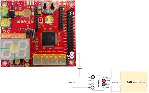
| + | The SJOne board is interfaced with the CAN Bus using the high-speed CAN transceiver MCP2551. The MCP2551 serves as the interface between a CAN protocol controller and the physical bus. It provides differential transmit and receive capability for the CAN protocol controller and is fully compatible with the ISO-11898 standard, including 24V requirements. | ||
| + | |||
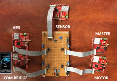
| + | Using the CAN transceivers, we have built a CAN bus board that is interfaced with five SJOne Boards - Master controller, Sensor Controller, GEO Controller, Motor Controller and Communication Bridge controller. | ||
| + | The communication between the boards is done via the CAN Bus. | ||
| + | {| | ||
| + | |[[File:CmpE243 F16 Thunderbolt CAN bus.jpg|thumb|left|500px|CAN Bus interface with SJOne Board]] | ||
| + | |[[File:CmpE243_F16_Thunderbolt_System_Design.JPG|thumb|right|480px|CAN Communication between the controllers]] | ||
| + | |} | ||
| + | |||
| + | |||
| + | '''CAN 11 bit Message ID Format''' | ||
| + | {| class="wikitable" | ||
| + | |- | ||
| + | ! scope="col"| Message Type | ||
| + | ! scope="col"| DEST | ||
| + | ! scope="col"| SRC | ||
| + | |||
| + | |- | ||
| + | ! scope="row"| 5 | ||
| + | | 3 | ||
| + | | 3 | ||
| + | |} | ||
| + | |||
| + | '''Message Types''' | ||
| + | {| class="wikitable" | ||
| + | |- | ||
| + | ! scope="col"| Message Type | ||
| + | ! scope="col"| Bits | ||
| + | |||
| + | |- | ||
| + | ! scope="row"| Start/Stop/Reset | ||
| + | | 00000 | ||
| + | |- | ||
| + | ! scope="row"| Data | ||
| + | | 00001 | ||
| + | |||
| + | |- | ||
| + | ! scope="row"| Action | ||
| + | | 00010 | ||
| + | |||
| + | |- | ||
| + | ! scope="row"| ACK | ||
| + | | 00011 | ||
| + | |||
| + | |- | ||
| + | ! scope="row"| Heartbeat | ||
| + | | 00100 | ||
| + | |} | ||
| + | |||
| + | '''DESTINATION''' | ||
| + | {| class="wikitable" | ||
| + | |- | ||
| + | ! scope="col"| Modules | ||
| + | ! scope="col"| Bits | ||
| + | |||
| + | |- | ||
| + | ! scope="row"| All Module | ||
| + | | 000 | ||
| + | |- | ||
| + | ! scope="row"| Motor | ||
| + | | 001 | ||
| + | |||
| + | |- | ||
| + | ! scope="row"| Master | ||
| + | | 010 | ||
| + | |||
| + | |- | ||
| + | ! scope="row"| GPS | ||
| + | | 011 | ||
| + | |||
| + | |- | ||
| + | ! scope="row"| COM_BRIDGE | ||
| + | | 100 | ||
| + | |||
| + | |- | ||
| + | ! scope="row"| Sensor | ||
| + | | 101 | ||
| + | |} | ||
| + | |||
| + | '''SOURCE''' | ||
| + | {| class="wikitable" | ||
| + | |- | ||
| + | ! scope="col"| Modules | ||
| + | ! scope="col"| Bits | ||
| + | |||
| + | |- | ||
| + | ! scope="row"| Sensor | ||
| + | | 000 | ||
| + | |- | ||
| + | ! scope="row"| Master | ||
| + | | 001 | ||
| + | |||
| + | |- | ||
| + | ! scope="row"| GPS | ||
| + | | 010 | ||
| + | |||
| + | |- | ||
| + | ! scope="row"| Motor | ||
| + | | 011 | ||
| + | |||
|- | |- | ||
| + | ! scope="row"| COM_BRIDGE | ||
| + | | 100 | ||
|} | |} | ||
| + | |||
| + | === PCAN Dongle and BusMaster === | ||
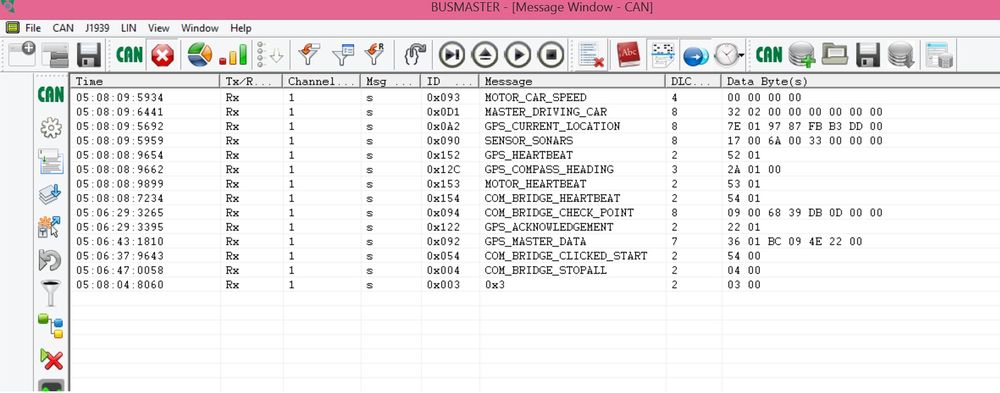
| + | We have used BusMaster to monitor the CAN messages between the various controllers. The GUI is useful to log all the information and is very helpful in debugging various messages and conditions in real-time. | ||
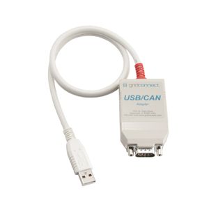
| + | The CAN bus USB adapter (PCAN Dongle) connects the CAN bus to the USB port of a computer, which also supplies the power to the adapter (no power supply needed) and Bus Master is used to display and debug the messages between the controllers. | ||
| + | |||
| + | [[File:CmpE243_F16_Thunderbolt_PCAN_Dongle.jpg|left|300px|thumb|PCAN Dongle]] | ||
| + | [[File:CmpE243_F16_Thunderbolt_CAN_Bus_master.jpg|center|1000px|thumb|BusMaster screenshot with all messages]] | ||
== Master Controller == | == Master Controller == | ||
| + | ==== Group Members ==== | ||
| + | * '''Saurabh Deshmukh''' | ||
| + | * '''Abhishek Singh''' | ||
=== Schedule === | === Schedule === | ||
| Line 144: | Line 462: | ||
|- | |- | ||
! scope="row"| 1 | ! scope="row"| 1 | ||
| − | | 10/ | + | | 10/12/2016 |
| 10/18/2016 | | 10/18/2016 | ||
| − | |||
| − | |||
| | | | ||
| + | * Decide/Develop the CAN message ID and node address for all controllers | ||
| + | | Completed | ||
| + | | 10/18/2016 | ||
|- | |- | ||
! scope="row"| 2 | ! scope="row"| 2 | ||
| − | | 10/ | + | | 10/19/2016 |
| 10/25/2016 | | 10/25/2016 | ||
| − | |||
| | | | ||
| − | | | + | * Integrate the Bluetooth module with the Master controller over CAN bus |
| + | | Completed | ||
| + | | 10/25/2016 | ||
|- | |- | ||
! scope="row"| 3 | ! scope="row"| 3 | ||
| 10/25/2016 | | 10/25/2016 | ||
| 11/01/2016 | | 11/01/2016 | ||
| − | |||
| − | |||
| | | | ||
| + | * Interface the Motor module with the Master controller over CAN bus | ||
| + | | Completed | ||
| + | | 11/01/2016 | ||
|- | |- | ||
! scope="row"| 4 | ! scope="row"| 4 | ||
| − | | 11/ | + | | 11/02/2016 |
| 11/08/2016 | | 11/08/2016 | ||
| − | |||
| | | | ||
| − | | | + | * Design the algorithm for navigation and obstacle avoidance |
| + | * Interface the sensor controllers with the Master controller over CAN bus | ||
| + | * Interfacing the Master controller with GPS module | ||
| + | | Completed | ||
| + | | 11/08/2016 | ||
|- | |- | ||
! scope="row"| 5 | ! scope="row"| 5 | ||
| − | | 11/ | + | | 11/09/2016 |
| 11/15/2016 | | 11/15/2016 | ||
| − | |||
| − | |||
| | | | ||
| + | * Designing of the kill switch | ||
| + | | Completed | ||
| + | | 11/15/2016 | ||
|- | |- | ||
! scope="row"| 6 | ! scope="row"| 6 | ||
| − | | 11/ | + | | 11/16/2016 |
| 11/22/2016 | | 11/22/2016 | ||
| − | |||
| | | | ||
| − | | | + | * Testing the Master module with all controllers interfaced |
| + | | Completed | ||
| + | | 11/22/2016 | ||
|- | |- | ||
! scope="row"| 7 | ! scope="row"| 7 | ||
| − | | 11/ | + | | 11/23/2016 |
| − | | 11/ | + | | 11/29/2016 |
| − | |||
| − | |||
| | | | ||
| + | * Take care of modifications and shortcomings if any | ||
| + | | Completed | ||
| + | | 11/29/2016 | ||
|- | |- | ||
! scope="row"| 8 | ! scope="row"| 8 | ||
| − | | 11/ | + | | 11/30/2016 |
| − | | | + | | 12/06/2016 |
| − | |||
| − | |||
| | | | ||
| + | * Improvise the communication on CAN bus | ||
| + | | Completed | ||
| + | | 12/06/2016 | ||
|- | |- | ||
! scope="row"| 9 | ! scope="row"| 9 | ||
| − | | | + | | 12/07/2016 |
| − | | | + | | 12/13/2016 |
| − | |||
| − | |||
| | | | ||
| + | * Final Testing of self driving car | ||
| + | | Completed | ||
| + | | 12/13/2016 | ||
|- | |- | ||
|} | |} | ||
=== Design & Implementation === | === Design & Implementation === | ||
| − | |||
| − | + | The Master is the main controller of the RC Car which accepts data from all other controllers and based on the data received, it takes the decision to avoid obstacles and guides the car to reach the destination. | |
| − | + | It is responsible for all the actions taken by the car. | |
=== Hardware Interface === | === Hardware Interface === | ||
| − | + | ||
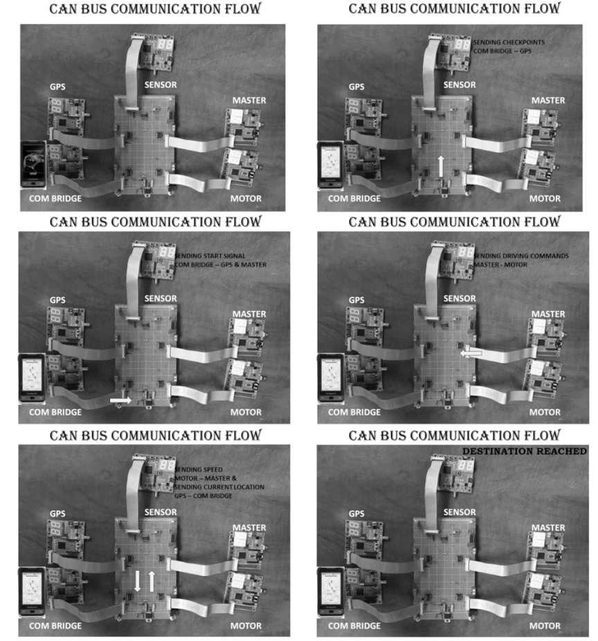
| + | [[File:Cmpe243_f16_thunderbolt_can_bus_flow.gif|center|1000px|thumb|CAN Communication between the controllers]] | ||
=== Software Design === | === Software Design === | ||
| − | + | * '''Heartbeat Implementation'''<br> | |
| + | The Master controller checks for heartbeat signals from all controllers in 1 Hz and glows the four LEDs on the Master controller SJOne board. | ||
| + | **'''''Receive Heartbeat signals from all other controllers''''' | ||
| + | |||
| + | BO_ 340 COM_BRIDGE_HEARTBEAT: 2 COM_BRIDGE | ||
| + | SG_ COM_BRIDGE_HEARTBEAT_UNSIGNED : 0|11@1+ (1,0) [0|0] "" MASTER | ||
| + | |||
| + | BO_ 338 GPS_HEARTBEAT: 2 GPS | ||
| + | SG_ GPS_HEARTBEAT_UNSIGNED : 0|11@1+ (1,0) [0|0] "" MASTER | ||
| + | |||
| + | BO_ 339 MOTOR_HEARTBEAT: 2 MOTOR | ||
| + | SG_ MOTOR_HEARTBEAT_UNSIGNED : 0|11@1+ (1,0) [0|0] "" MASTER | ||
| + | |||
| + | BO_ 336 SENSOR_HEARTBEAT: 2 SENSOR | ||
| + | SG_ SENSOR_HEARTBEAT_UNSIGNED : 0|11@1+ (1,0) [0|0] "" MASTER | ||
| + | |||
| + | * '''Data received from the Communication Bridge Controller'''<br> | ||
| + | The following signals are received by the Master Controller from the Com Bridge Controller | ||
| + | |||
| + | **'''''Start signal from Android App''''' | ||
| + | |||
| + | BO_ 84 COM_BRIDGE_CLICKED_START: 2 COM_BRIDGE | ||
| + | SG_ COM_BRIDGE_CLICKED_START_UNSIGNED : 0|11@1+ (1,0) [0|0] "" MASTER,GPS | ||
| + | |||
| + | **'''''Stop signal from Android App''''' | ||
| + | |||
| + | BO_ 4 COM_BRIDGE_STOPALL: 2 COM_BRIDGE | ||
| + | SG_ COM_BRIDGE_STOPALL_UNSIGNED : 0|11@1+ (1,0) [0|0] "" MASTER | ||
| + | |||
| + | **'''''Reset signal from Android App''''' | ||
| + | |||
| + | BO_ 3 COM_BRIDGE_RESET: 2 COM_BRIDGE | ||
| + | SG_ COM_BRIDGE_RESET_UNSIGNED : 0|11@1+ (1,0) [0|0] "" MASTER,GPS,MOTOR,SENSOR | ||
| + | |||
| + | * '''Data received from the Sensor Controller'''<br> | ||
| + | The following signals are received by the Master Controller from the Sensor Controller to decide on Obstacle avoidance | ||
| + | |||
| + | BO_ 144 SENSOR_SONARS: 8 SENSOR | ||
| + | SG_ SENSOR_SONARS_LEFT_UNSIGNED : 0|16@1+ (1,0) [0|0] "inches" MASTER,MOTOR,COM_BRIDGE | ||
| + | SG_ SENSOR_SONARS_RIGHT_UNSIGNED : 16|16@1+ (1,0) [0|0] "inches" MASTER,MOTOR,COM_BRIDGE | ||
| + | SG_ SENSOR_SONARS_FRONT_UNSIGNED : 32|16@1+ (1,0) [0|0] "inches" MASTER,MOTOR,COM_BRIDGE | ||
| + | SG_ SENSOR_SONARS_BACK_UNSIGNED : 48|16@1+ (1,0) [0|0] "inches" MASTER,MOTOR,COM_BRIDGE | ||
| + | |||
| + | * '''Data received from and sent to Motor Controller''' <br> | ||
| + | The below signal ''MASTER_DRIVING_CAR'' is sent by the Master Controller to the Motor controller, which is responsible to navigate the car. | ||
| + | The signals drive, steer and speed that are sent by the Master to the Motor decide the direction and speed of the car. | ||
| + | |||
| + | **'''''Signals drive, steer and speed that are sent by the Master to the Motor decide the direction and speed of the car''''' | ||
| + | |||
| + | BO_ 209 MASTER_DRIVING_CAR: 8 MASTER | ||
| + | SG_ MASTER_DRIVE_ENUM : 0|4@1+ (1,0) [0|0] "" MOTOR,COM_BRIDGE | ||
| + | SG_ MASTER_STEER_ENUM : 4|4@1+ (1,0) [0|0] "" MOTOR,COM_BRIDGE | ||
| + | SG_ MASTER_SPEED_ENUM : 8|4@1+ (1,0) [0|0] "" MOTOR,COM_BRIDGE | ||
| + | |||
| + | **'''''Speed signal received from Motor to Master | ||
| + | |||
| + | BO_ 147 MOTOR_CAR_SPEED: 4 MOTOR | ||
| + | SG_ MOTOR_SPEED_DATA_UNSIGNED : 0|8@1+ (1,0) [0|0] "" MASTER,COM_BRIDGE | ||
| + | SG_ MOTOR_DISTANCE_FROM_START_POINT_UNSIGNED : 8|8@1+ (1,0) [0|0] "meters" MASTER,COM_BRIDGE | ||
| + | |||
| + | * '''Data received from GEO Controller'''<br> | ||
| + | The GEO Controller sends the following data to the Master controller | ||
| + | |||
| + | **'''''Distance to next checkpoint, to final destination, turn angle and is_final flag''''' | ||
| + | |||
| + | BO_ 146 GPS_MASTER_DATA: 7 GPS | ||
| + | SG_ GEO_DATA_TURNANGLE_SIGNED : 0|16@1+ (0.1,-180) [-180|180] "degrees" MASTER,MOTOR | ||
| + | SG_ GEO_DATA_ISFINAL_SIGNED : 16|1@1+ (1,0) [0|0] "" MASTER,MOTOR | ||
| + | SG_ GEO_DATA_DISTANCE_TO_FINAL_DESTINATION_SIGNED : 17|16@1+ (0.1,0) [0|0] "meters" MASTER,MOTOR | ||
| + | SG_ GEO_DATA_DISTANCE_TO_NEXT_CHECKPOINT_SIGNED : 33|16@1+ (0.01,0) [0|0] "meters" MASTER,MOTOR | ||
=== Implementation === | === Implementation === | ||
| − | + | The following tasks are done in the periodic callbacks: | |
| + | * In 1Hz function | ||
| + | ** Reset CAN Bus if BUS off | ||
| + | ** Heartbeats from all modules to check if modules are active, by blinking LED's. | ||
| + | |||
| + | * In 10Hz function | ||
| + | ** Decision making based on obstacle avoidance algorithm | ||
| + | ** Feedback loop speed RPM - high, low, medium | ||
| + | |||
| + | * In 100Hz function | ||
| + | ** Receiving data from other controllers - heartbeat etc. | ||
| + | <br> | ||
| + | |||
| + | [[File: CmpE243 F16 Thunderbolt Master Flow Diagram.jpg|center|frame]] | ||
=== Testing & Technical Challenges === | === Testing & Technical Challenges === | ||
| − | + | Initially we were accepting data from the sensor and sending driving command to motor in 10 Hz periodic callback, but we were getting poor response for obstacle avoidance. So we received sensor data and sent the motor drive commands in 100hz, and processing was done in 10Hz. Because of this car response time was reduced and now car is more responsive for avoiding obstacle around it. | |
| − | |||
== Sensor Controller == | == Sensor Controller == | ||
| Line 235: | Line 645: | ||
{| class="wikitable" | {| class="wikitable" | ||
|- | |- | ||
| − | ! scope="col"| | + | ! scope="col"| Sr No |
| − | ! scope="col"| | + | ! scope="col"| Start Date |
| + | ! scope="col"| End Date | ||
! scope="col"| Task | ! scope="col"| Task | ||
| − | |||
| − | |||
! scope="col"| Status | ! scope="col"| Status | ||
| + | ! scope="col"| Actual Completion Date | ||
| + | ! scope="col"|Problems/Delays | ||
|- | |- | ||
! scope="row"| 1 | ! scope="row"| 1 | ||
| − | | 10/ | + | | 10/05/2016 |
| + | | 10/11/2016 | ||
| | | | ||
| − | * Choose appropiate components | + | * Choose appropiate components |
| − | |||
* Read through wiki to find out components used in earlier projects.<br> | * Read through wiki to find out components used in earlier projects.<br> | ||
* Ordered additional ultrasonic sensors. | * Ordered additional ultrasonic sensors. | ||
| + | |Complete | ||
| + | | 10/11/2016 | ||
| | | | ||
| − | |||
|- | |- | ||
! scope="row"| 2 | ! scope="row"| 2 | ||
| − | | 10/ | + | | 10/12/2016 |
| − | | | + | | 10/18/2016 |
| + | |||
| + | | | ||
* Sensor Data Sheet Review with team. | * Sensor Data Sheet Review with team. | ||
* Follow up on ordered parts | * Follow up on ordered parts | ||
| − | | | + | |Complete |
| − | + | | 10/18/2016 | |
| | | | ||
| − | |||
|- | |- | ||
! scope="row"| 3 | ! scope="row"| 3 | ||
| − | | 10/ | + | | 10/19/2016 |
| − | | | + | | 10/25/2016 |
| − | |||
| − | |||
| − | |||
| − | |||
| | | | ||
| + | * Test the Individual sensors to get accurate measurements according to data sheet | ||
| + | * Determine pins and architecture of board | ||
| + | |Complete | ||
| + | |10/25/2016 | ||
| | | | ||
|- | |- | ||
! scope="row"| 4 | ! scope="row"| 4 | ||
| − | | 10/ | + | | 10/26/2016 |
| − | | | + | | 11/01/2016 |
| − | |||
| − | |||
| − | |||
| | | | ||
| + | * Develop entire board algorithm for all sensors | ||
| + | |Complete | ||
| + | |11/01/2016 | ||
| | | | ||
|- | |- | ||
! scope="row"| 5 | ! scope="row"| 5 | ||
| − | | | + | | 11/02/2016 |
| − | | | + | | 11/08/2016 |
| − | |||
| − | |||
| − | |||
| | | | ||
| + | * Created 3D Printed Mount for all ultrasonic sensors on car and test it. | ||
| + | * Start implementation of CAN bus by testing sending and receiving of messages | ||
| + | |Complete | ||
| + | |11/08/2016 | ||
| | | | ||
|- | |- | ||
! scope="row"| 6 | ! scope="row"| 6 | ||
| − | | 11/ | + | | 11/09/2016 |
| − | | | + | | 11/15/2016 |
| − | |||
| − | |||
| − | |||
| − | |||
| | | | ||
| + | * Complete implementation of the sensor controller with the Master controller over CAN bus | ||
| + | * Fine-tune algorithms for sensor. | ||
| + | |Complete | ||
| + | |11/15/2016 | ||
| | | | ||
|- | |- | ||
! scope="row"| 7 | ! scope="row"| 7 | ||
| − | | 11/ | + | | 11/16/2016 |
| + | | 11/22/2016 | ||
| + | | | ||
| + | * Test the implementation for multiple sensors and debugging the issue. | ||
| + | * Decide upon additional I/O such as lights | ||
| + | |Complete | ||
| + | |11/22/2016 | ||
| | | | ||
| − | + | |- | |
| − | + | ! scope="row"| 8 | |
| + | | 11/23/2016 | ||
| + | | 11/29/2016 | ||
| | | | ||
| − | * | + | * Optimize the code and testing for stability and report. |
| − | | | + | |Complete |
| − | | | + | |11/29/2016 |
| + | | Right and left sensor interference with each other. Must give separate triggering pins instead of combined triggering. | ||
|- | |- | ||
! scope="row"| 8 | ! scope="row"| 8 | ||
| − | | 11/ | + | | 11/30/2016 |
| − | | | + | | 12/06/2016 |
| − | |||
| | | | ||
| − | * | + | * Testing and Debugging. |
| − | | | + | |Complete |
| + | |12/06/2016 | ||
| | | | ||
|- | |- | ||
| Line 322: | Line 745: | ||
=== Design & Implementation === | === Design & Implementation === | ||
| − | + | This section goes over the design and implementation of the sensor controller. | |
| + | The sensor controller is the main controller for everything dealing with sensors. The sensor controller's main role is to provide distance of the closest objects around the car to the master controller in a sufficient amount of time. Knowing the proximity of objects around the car helps it navigate and maneuver around them in order to reach the destination without crashing. For this project, the car must be able to know what is to the right, middle, and left of the car in order to adjust accordingly. In rare cases, the car must be able to know the distance behind it for reversing out of certain situations. | ||
| + | In addition to the sonar sensors, the sensor board is also responsible for the headlights of the car. | ||
| + | Finally, the sensor module is also connected to the CAN bus in order to communicate with other controllers on the network. | ||
=== Hardware Design === | === Hardware Design === | ||
| − | |||
| − | |||
| − | |||
| − | |||
| − | |||
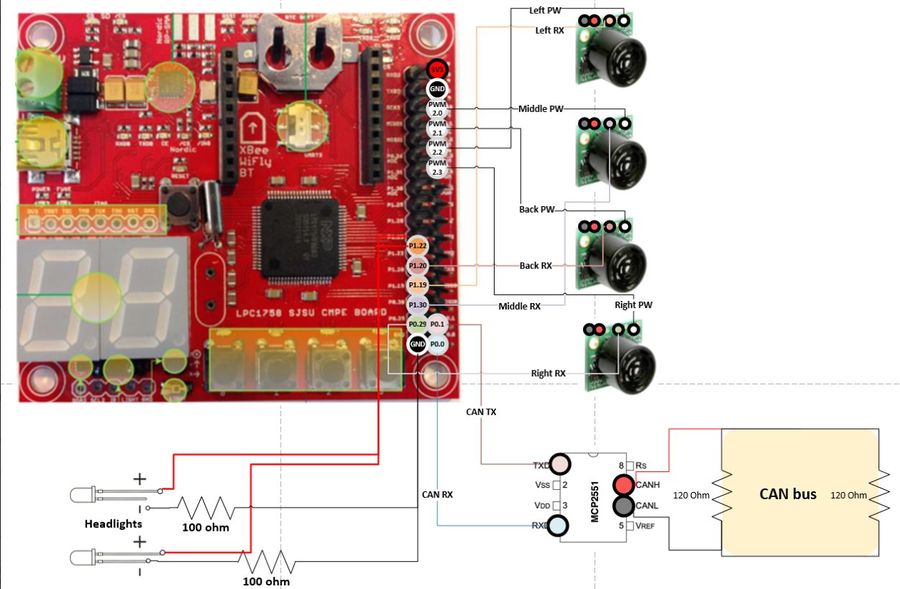
| − | + | The main components of the sensor board consists of four ultrasonic sensors. Three sensors (left, middle, and right) are placed in the front of the car and one sensor is placed in the back. | |
| − | + | <br><br> | |
| + | '''MaxSonar MB1010 Sensor''' | ||
| + | |||
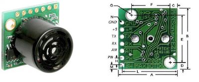
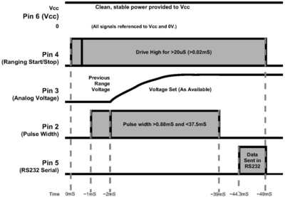
| + | The sensors are MB1010 LV-MaxSonar-EZ21 Ultrasonic Rangefinder sonar sensors, which can range from 6-inches to 254-inches with 1-inch resolution. Any object detected 6-inches or shorter is outputted as 6-inches. They are used in PW mode for outputting. The MaxSonar MB1010 sonar sensors require only four pins to be used in PW mode. The pins that need to be connected are the +5, GND, RX, and PW pins. The +5V and GND pins for the four sensors are all connected to the SJOne board's 3v3 and GND pins, respectively. Each of the sensors are triggered with a GPIO pin individually. The resulting output pin (PW) are connected to the PWM pins of the SJOne board individually. The sensors need to be triggered (high voltage pulse) for atlas 20 microseconds in order to start ranging. It finishes the ranging for PW in about 40 ms and the entire ranging in about 50 ms. | ||
| + | |||
| + | [[File:CmpE243_F16_Thunderbolt_MaxSonar_Sensor_MB1010.jpg|left|400px|thumb|MaxSonar MB1010 Sensor]] | ||
| + | [[File:CmpE243_F16_Thunderbolt_Sensors_waveform.png|center|400px|thumb|Timing Diagram]] | ||
| + | |||
| + | '''Mounting of Sensors'''<br> | ||
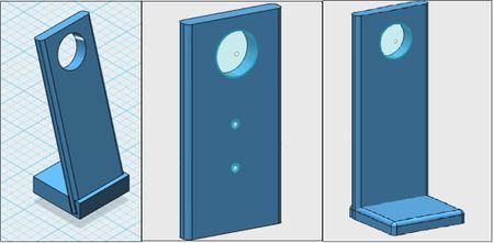
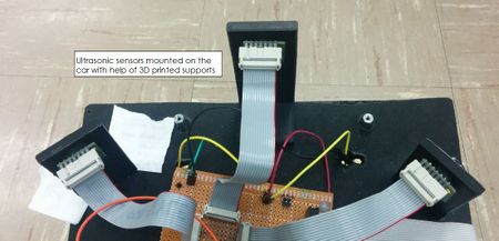
| − | + | The stands for holding the sensors are curved such that the sensors are aimed with a positive slope and not horizontally. This decision is made in order to avoid interference with the ground due to the wide range of detection by the sensors. | |
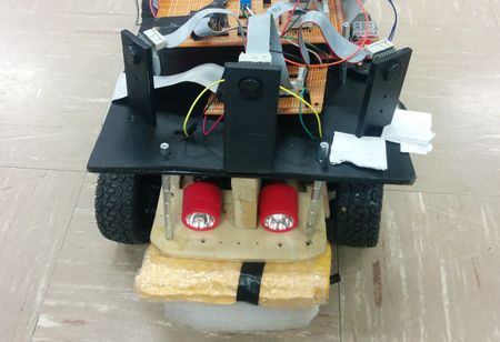
| − | + | The middle sensors for the front and back are placed directly in the middle of the car. The left and right sensors are placed at a 45 degree angle to the middle and side of the car in order to detect objects closer to the front of the car near the sides. This decision is made due to the fact that the car is traveling forward, so being able to detect objects closer to the front of the car as soon as possible is of the utmost importance. | |
| − | + | We have 3D printed the supports for mounting the sensors as seen below. The software used is 123D Design. | |
| − | + | {| | |
| − | + | |[[File:CmpE243_F16_Thunderbolt_Sensors_mount.JPG|450px|left|thumb|3D Design for mounting the sensors]] | |
| − | + | |[[File:CmpE243_F16_Thunderbolt_Sensors_mounting.JPG|450px|right|thumb|Mounting of sensors on the RC Car]] | |
| + | |} | ||
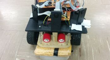
| + | [[File:CmpE243_F16_Thunderbolt_Sensors_mounting3.jpg|450px|left|thumb|Front view of the car with sensors mounted and headlights]] | ||
| − | + | <br><br><br><br><br><br><br><br> | |
| − | + | <br><br><br><br><br><br><br><br><br><br><br> | |
=== Hardware Interface === | === Hardware Interface === | ||
| − | + | [[File:CmpE243_F16_Thunderbolt_Sensors_HW_interface.jpg|left|900px|thumb|Hardware Interface between SJOne board and Sensors]] | |
| + | {| class="wikitable" | ||
| + | |- | ||
| + | ! scope="col"| Sr.No | ||
| + | ! scope="col"| SJOne Board | ||
| + | ! scope="col"| Sensors interface | ||
| + | |||
| + | |- | ||
| + | ! scope="row"| 1 | ||
| + | | P2.0 (PWM) | ||
| + | | TX Front | ||
| + | |||
| + | |- | ||
| + | ! scope="row"| 2 | ||
| + | | P2.1 (PWM) | ||
| + | | TX Back | ||
| + | |- | ||
| + | ! scope="row"| 3 | ||
| + | | P 2.2 | ||
| + | | TX Left | ||
| + | |||
| + | |- | ||
| + | ! scope="row"| 4 | ||
| + | | P 2.3 | ||
| + | | TX Right | ||
| + | |- | ||
| + | ! scope="row"| 5 | ||
| + | | 3V3 | ||
| + | | +5V (Sensors) | ||
| + | |||
| + | |- | ||
| + | ! scope="row"| 6 | ||
| + | | GND | ||
| + | | GND (sensors) | ||
| + | |||
| + | |- | ||
| + | ! scope="row"| 7 | ||
| + | | P0.0 | ||
| + | | CAN RX | ||
| + | |- | ||
| + | ! scope="row"| 8 | ||
| + | | P0.1 | ||
| + | | CAN TX | ||
| + | |- | ||
| + | ! scope="row"| 9 | ||
| + | | P0.29 | ||
| + | | Left Sensor (RX) | ||
| + | |- | ||
| + | ! scope="row"| 10 | ||
| + | | P0.30 | ||
| + | | Front and Back Sensor (RX) | ||
| + | |- | ||
| + | ! scope="row"| 11 | ||
| + | | P1.19 | ||
| + | | Right Sensor (RX) | ||
| + | |- | ||
| + | |} | ||
| + | <br><br><br><br><br><br><br><br><br><br><br><br><br><br><br><br><br> | ||
=== Software Design === | === Software Design === | ||
| − | + | ||
| + | The following signals are received by the Master Controller from the Com Bridge Controller | ||
| + | **'''''Heartbeat signal to Master''''' | ||
| + | BO_ 336 SENSOR_HEARTBEAT: 2 SENSOR | ||
| + | SG_ SENSOR_HEARTBEAT_UNSIGNED : 0|11@1+ (1,0) [0|0] "" MASTER | ||
| + | |||
| + | **'''''Left, Right, front and back Sensor values sent to Master | ||
| + | BO_144 SENSOR_SONARS: 8 SENSOR | ||
| + | SG_ SENSOR_SONARS_LEFT_UNSIGNED : 0|16@1+ (1,0) [0|0] "inches" MASTER | ||
| + | SG_ SENSOR_SONARS_RIGHT_UNSIGNED : 16|16@1+ (1,0) [0|0] "inches" MASTER | ||
| + | SG_ SENSOR_SONARS_FRONT_UNSIGNED : 32|16@1+ (1,0) [0|0] "inches" MASTER | ||
| + | SG_ SENSOR_SONARS_BACK_UNSIGNED : 48|16@1+ (1,0) [0|0] "inches" MASTER | ||
=== Implementation === | === Implementation === | ||
| − | |||
| − | + | <br> | |
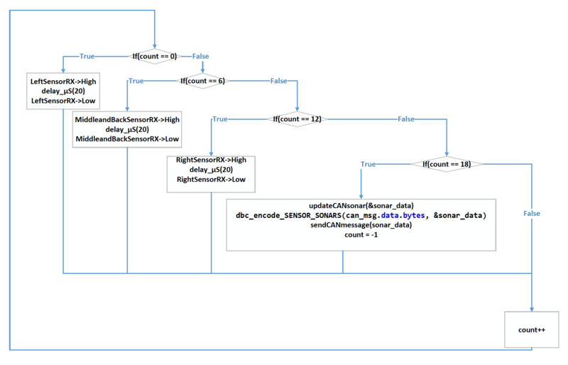
| − | + | The idea behind implementing the algorithm for the sensor is to make sure that the beam from the sensors do not collide with each other, which would corrupt the data. | |
| − | + | Thus, we trigger left, front and back, and right sensors individually. By triggering the front and back sensors at the same time, 50 ms of time is saved in sending the data to the master controller. <br> Every sensor takes a calibration cycle of 49 ms. | |
| + | Also we consider the initial power up delay of 250 ms.<br> The sensor task scheduling is implemented using a count method, which can be seen in ''sensor.cpp file''. <br><br> | ||
| + | [[File:CmpE243_F16_Thunderbolt_FlowDiagram.png|800px|center|thumb|Flow Diagram(100 hz function)]] | ||
| + | <br> | ||
| − | |||
| − | |||
| − | |||
| − | + | For getting values from sensor we keep the RX pin high for 50ms (as per data sheet). This is the ample time for the sensor to send the beam and get the reflected beam back. <br> | |
| − | + | To inform the master that sensor controller is still on the CAN bus , we send a Heartbeat signal to master every 1 second (1 hz task). <br> | |
| − | + | We implement the following in the 100 Hz periodic task, which executes every 10 ms (above diagram). The sensor function composes of three triggering (RX) if-statements. <br> The triggering statements are for the left sensor, middle and back sensors, and the right sensor, in that order. Each triggering occurs 60 ms between each other to avoid interference between sensors. | |
| − | + | * When the count is zero (0 ms has passed from the beginning of ranging), the left sensor is first triggered for 20 microseconds.<br> | |
| + | * When the count is 6 (60 ms has passed from the beginning of ranging), the middle and back sensors are triggered for 20 microseconds. | ||
| + | * When the count is 12 (120 ms has passed from the beginning of ranging), the right sensor is triggered for 20 microseconds. | ||
| + | * Finally, when the count is 18 (180 ms has passed from the beginning of ranging), all sensors have completed ranging and all sensor data is updated, encoded, and sent over the CAN bus. | ||
| + | * The count is also reset to -1. The count is also incremented once at the end of this 100 Hz task. <br><br> | ||
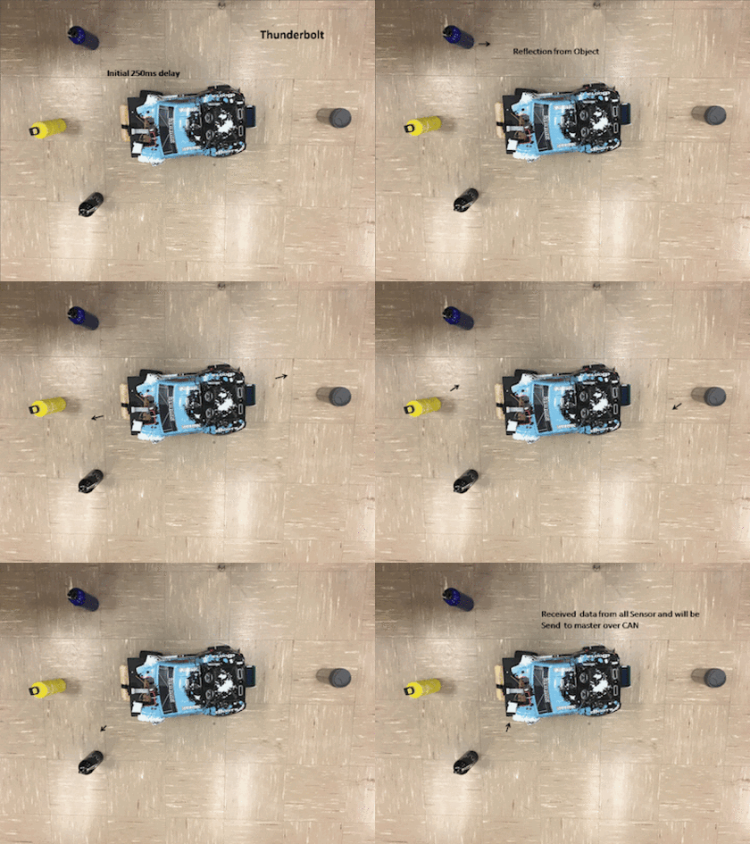
| − | + | Below is the image that shows the actuating sequence of the sensors. | |
| − | |||
| − | |||
| − | |||
| − | + | [[File:CmpE243 F16 Thunderbolt SensorActuation.gif|left|800px|thumb]] | |
| + | <br><br><br><br><br><br><br><br><br><br><br><br><br><br><br><br><br><br><br> | ||
| + | '''Headlights''' | ||
| − | + | [[File:CmpE243_F16_Thunderbolt_Headlights.JPG|left|350px|thumb|Light sensor based Headlights]] | |
| − | + | We have implemented light sensor based headlights on our car. The headlights are based on the light sensor available on the SJOne board. <br> The light sensor on the board determines whether it is day or night and if it is night or less light is available i.e. during the evening time, then the headlights are automatically turned on. | |
| − | |||
| − | |||
| − | |||
| − | |||
| − | |||
| − | |||
| − | |||
| − | |||
| − | |||
| − | |||
| − | |||
| − | |||
| − | |||
| − | |||
| − | |||
| − | |||
| − | |||
| − | |||
| + | <br><br><br><br><br><br><br><br><br><br><br> | ||
| − | + | === Testing & Technical Challenges === | |
| − | + | <br> | |
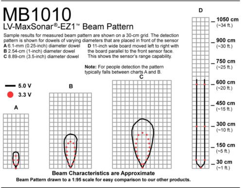
| − | + | [[File:CmpE243 F16 Thunderbolt Sensors SensorWideDetect.png|left|500px|thumb|Wide detect pattern of the sensors]] | |
| − | + | <br> | |
| − | + | 1. '''Delay time of RX''' | |
| − | + | Initially, we wanted to keep the timing for each sensor triggering to be as short as possible in order to send the sensor data to the master controller as quickly as possible. The triggering time between sensors was initially put at 20 ms. We did not see any problems due to having a one second delay between sensors in order to read the values from debug printf statements. However, once that printf delay was removed, the sensor data was not constant. We also tried a 40 ms delay since that was how long it took to trigger for PW. We still encountered problems and finally settled on the maximum of 50 ms delay between sensors. | |
| − | < | + | <br> |
| − | + | 2. '''Angle of sonar sensors''' | |
| − | + | The angle of the sonar sensors provided a problem in early testing. Due to the wide range of detection by these specific sensors, the sensors' ranging would interfere with the ground when they were placed horizontally and not too far above the ground. To fix this problem, the sensors were tilted toward the sky, which shifted the range of detection to be above the ground. | |
| − | |||
| − | + | <br> | |
| − | + | 3. '''Senor interference with each other''' | |
| − | + | Initially, we wanted to trigger the right and left sensors at the same time. We thought that there was ample distance between the sensors such that we can trigger them at the same time without interference. However, we continued to get unstable data, which may be due to wide sensing of the particular sensors we used, MB1010. We decided to trigger each sensor at a time with exception to triggering the middle and back sensors at the same time. | |
| − | + | <br><br><br><br> | |
| − | + | <br><br><br><br><br> | |
| − | == | + | == Motor & I/O Controller == |
==== Group Members ==== | ==== Group Members ==== | ||
| − | * ''' | + | * '''Krishank Mehta''' |
| − | * ''' | + | * '''Neha Biradar''' |
| − | * '''Saurabh Deshmukh''' | + | * '''Saurabh Ravindra Deshmukh''' |
=== Schedule === | === Schedule === | ||
{| class="wikitable" | {| class="wikitable" | ||
|- | |- | ||
| − | ! scope="col"| | + | ! scope="col"| Sr No |
| − | ! scope="col"| | + | ! scope="col"| Start Date |
| + | ! scope="col"| End Date | ||
! scope="col"| Task | ! scope="col"| Task | ||
| − | |||
| − | |||
! scope="col"| Status | ! scope="col"| Status | ||
| + | ! scope="col"| Actual Completed Date | ||
| + | ! scope="col"| Problems Encountered if any | ||
|- | |- | ||
! scope="row"| 1 | ! scope="row"| 1 | ||
| − | | | + | | 9/19/2016 |
| + | | 9/27/2016 | ||
| | | | ||
| − | * | + | * Understanding the motor and PWM concept. |
| − | | | + | | Completed |
| − | + | | 9/25/2016 | |
| − | |||
| | | | ||
| − | |||
|- | |- | ||
! scope="row"| 2 | ! scope="row"| 2 | ||
| − | | 10/ | + | | 9/28/2016 |
| + | | 10/4/2016 | ||
| | | | ||
| − | * | + | * Testing Servo and DC motor using RC Transmitter and Receiver. |
| − | + | | Completed | |
| − | | | + | | 10/5/2016 |
| − | |||
| | | | ||
| − | |||
|- | |- | ||
! scope="row"| 3 | ! scope="row"| 3 | ||
| − | | 10/ | + | | 10/7/2016 |
| + | | 10/10/2016 | ||
| + | | | ||
| + | * Testing and interfacing of servo and DC motor with SJOne Board | ||
| + | |Completed | ||
| + | |10/10/2016 | ||
| + | |Problem with finding the starting pwm pattern for DC Motor | ||
| + | |- | ||
| + | ! scope="row"| 4 | ||
| + | | 10/11/2016 | ||
| + | | 10/18/2016 | ||
| + | | | ||
| + | * Design of CAN message ID for motor controller. | ||
| + | |Completed | ||
| + | |10/17/2016 | ||
| + | | | ||
| + | |- | ||
| + | ! scope="row"| 5 | ||
| + | | 10/20/2016 | ||
| + | | 10/24/2016 | ||
| + | | | ||
| + | * LCD module programming and understanding the RPM sensor interfacing. | ||
| + | |Completed | ||
| + | | 10/24/2016 | ||
| + | | | ||
| + | |- | ||
| + | ! scope="row"| 6 | ||
| + | | 10/26/2016 | ||
| + | | 10/28/2016 | ||
| | | | ||
| − | * | + | * Design a power circuit on RC car with motors interfaced to SJOne board. |
| − | * | + | * Integrating speed sensor. |
| − | | | + | |Completed |
| − | + | |11/26/2016 | |
| + | | | ||
| + | |- | ||
| + | ! scope="row"| 7 | ||
| + | | 11/01/2016 | ||
| + | | 11/08/2016 | ||
| | | | ||
| + | * Establishing reliable CAN communication for motors with master controller. | ||
| + | |Completed | ||
| + | |11/07/2016 | ||
| | | | ||
|- | |- | ||
| − | ! scope="row"| | + | ! scope="row"| 8 |
| − | | | + | | 11/15/2016 |
| + | | 11/18/2016 | ||
| | | | ||
| − | * | + | * Interfacing of sensors with motors and testing obstacle avoidance . |
| + | | Completed | ||
| + | |11/07/2016 | ||
| | | | ||
| − | + | |- | |
| + | ! scope="row"| 9 | ||
| + | | 11/18/2016 | ||
| + | | 11/22/2016 | ||
| | | | ||
| + | * Integrating it with the master controller, testing and debugging | ||
| + | | Completed | ||
| + | | 11/20/2016 | ||
| | | | ||
|- | |- | ||
| − | ! scope="row"| | + | |} |
| − | | | + | |
| + | === Design & Implementation === | ||
| + | The Motor IO controller works as per the commands from the Master controller. The motor module is responsible for the running on the car, its direction and speed. The IO module consists of LCD and backlights. | ||
| + | |||
| + | === Hardware Design === | ||
| + | |||
| + | ====Motor Module==== | ||
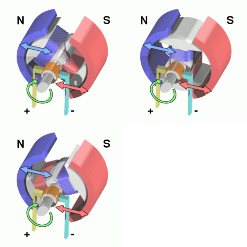
| + | The Motor module consists of servo motor, DC motor and speed sensor module. The servo motor is responsible for steering of the car and the DC motor is responsible for speed control.<br> | ||
| + | The Master controller sends signals of drive, speed and steer to the motor controller to navigate the car, based on the information received from Sensors and GPS. | ||
| + | |||
| + | '''DC Motor'''<br> | ||
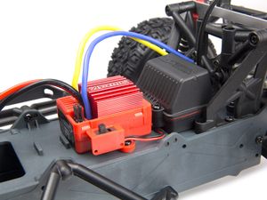
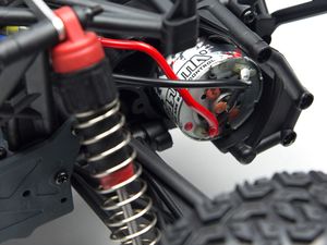
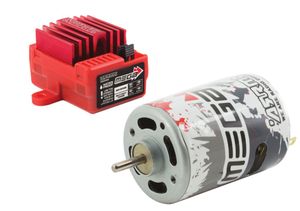
| + | In the car, we have the ARRMA MEGA waterproof 35A ESC, combined with the 15T MEGA Brushed Motor. | ||
| + | The MEGA ESC is designed to be used with the supplied NiMh Battery Pack and can easily handle 2S LiPo battery packs or 7 cell 8.4V NiMh battery packs. | ||
| + | {| | ||
| + | |[[File:CmpE243_F16_Thunderbolt_DC_Brush_Motor_cycle.gif| 250px | left| thumb |DC Brush Motor cycle]] | ||
| + | |[[File:CmpE243_F16_Thunderbolt_Motor_module ESC .jpg| 300px | right| thumb | ESC]] | ||
| + | |[[File:CmpE243_F16_Thunderbolt_Motor_module_Brushed_Motor.jpg| 300px | right| thumb | Brushed DC motor]] | ||
| + | |} | ||
| + | |||
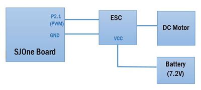
| + | The ESC (Electronic Speed Control) is connected to the SJOne board to generate the PWM as shown in the block diagram below, which is connected to the DC Motor. | ||
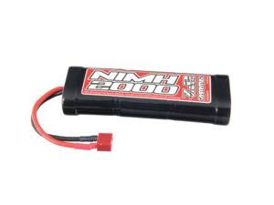
| + | It is powered by a ARRMA 6 Cell 2000mAh 7.2 volt NiMh Battery. | ||
| + | |||
| + | {| | ||
| + | |[[File:CmpE243_F16_Thunderbolt_7.2V_NiMh_Battery.png| 300px | left| thumb | ESC]] | ||
| + | |[[File:CmpE243_F16_Thunderbolt_Motor_module_ESC_with_Brushed_Motor.jpg| 300px | center| thumb |DC Motor with ESC]] | ||
| + | |[[File:CmpE243_F16_Thunderbolt_DC_Motor_Interface.JPG| 400px | right| thumb | DC Motor Interface with SJOne Board]] | ||
| + | |} | ||
| + | |||
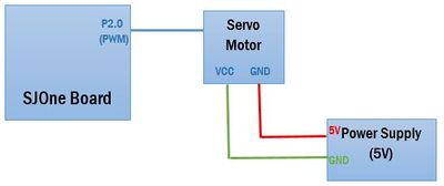
| + | '''Servo Motor'''<br> | ||
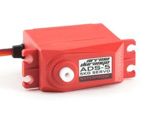
| + | The Servo motor in our car is ADS-5 Steering Servo, which will provide fast and consistent steering response on the most demanding surfaces. This servo provides 5kg/cm (70oz/inch) of torque.<br> | ||
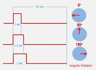
| + | The servo motor is connected to the SJOne board and provided PWM signal to control the steering of the car in 5 directions - far left, left, center, right, far right. | ||
| + | {| | ||
| + | |[[File:CmpE243_F16_Thunderbolt_servo_motor_rotation.gif| 320px|left|thumb| Servo motor rotation]] | ||
| + | |[[File:CmpE243 F16 Thunderbolt Motor module steering servo.jpg | 300px|center|thumb| Steering Servo Motor]] | ||
| + | |[[File:CmpE243_F16_Thunderbolt_Servo_Motor_Interface.JPG|400px|right|thumb|Servo Motor Interface with SJOne Board]] | ||
| + | |} | ||
| + | <br> | ||
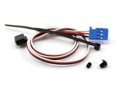
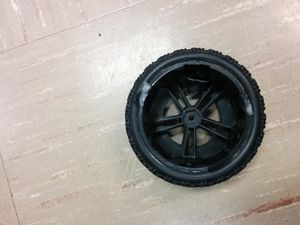
| + | '''Speed Sensor''' | ||
| + | {| | ||
| + | |[[File:CmpE243_F16_Thunderbolt_Motor_module_Traxxas_Speed_Sensor.jpg|240px|left|thumb|Traxxas Speed Sensor]] | ||
| + | |[[File:CmpE243_F16_Thunderbolt_Magnets_on_wheel.jpg|300px|center|thumb|10 magnets on wheel]] | ||
| + | |} | ||
| + | <br> | ||
| + | |||
| + | ==== IO Module ==== | ||
| + | |||
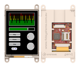
| + | The IO Module consists of two LCD Modules - Picaso Integrated Display Module and Serial Liquid Crystal Display Module and backlights based on the direction and movement of the car. <br><br> | ||
| + | |||
| + | [[File:CmpE243_F16_Thunderbolt_LCD.png|left|250px|thumb|IO Module gen4-uLCD-32PT]] | ||
| + | [[File:CmpE243 F16 Thunderbolt IO Graphic LCD.JPG|right|350px|thumb|IO Module gen4-uLCD-32PT]] | ||
| + | |||
| + | '''LCD Display - Picaso Integrated Display Module''' <br> | ||
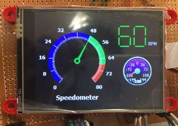
| + | We are using two LCD modules in the project. One of them is a gen4 3.2” Picaso Integrated Display Module, which features a TFT LCD Display. <br> The processor includes a microSD memory storage, 13 customizable GPIO, 2 serial ports and a Master I2C interface, along with multiple millisecond resolution timers, and Audio Generation. <br> The Model number we are using is ''gen4-uLCD-32PT''. | ||
| + | <br> The data from the Motor controller and GPS controller is sent to the LCD Module through I2C. <br> | ||
| + | |||
| + | LCD displays the following information: | ||
| + | |||
| + | |||
| + | Speedometer | ||
| + | Compass turn angle | ||
| + | <br><br> | ||
| + | |||
| + | [[File:CmpE243_F16_Thunderbolt_LCD_results.jpg|right|320px|320px|thumb|LCD Display]] | ||
| + | |||
| + | '''LCD Display - Serial Liquid Crystal Display Module''' <br> | ||
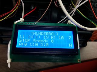
| + | The second LCD is a 4 line * 20 characters Serial Liquid Crystal Display Module. The Model number we are using is ''NHD-0420D3Z-NSW-BBW-V3''. | ||
| + | <br> This display uses a built-in PIC16F690 for serial communication. 100mS delay is required upon power-up for the built-in PIC to initialize the display controller. <br> The data from the Sensor controller, Motor controller and GPS controller is sent to the LCD Module through I2C. <br> | ||
| + | |||
| + | LCD displays the following information: | ||
| + | |||
| + | 1st Line - THUNDERBOLT | ||
| + | 2nd Line - Sensor Controller Data - Left Sensor, Front Sensor, Right Sensor, Back Sensor Readings | ||
| + | 3rd Line - Motor Controller Data - Direction, Speed | ||
| + | 4th Line - GPS Controller Data - Final distance, distance to next checkpoint | ||
| + | |||
| + | Also once the car reaches the destination, "''Destination reached''" message is flashed on the LCD. | ||
| + | |||
| + | '''Backlights''' | ||
| + | [[File:CmpE243_F16_Thunderbolt_IO_Module_Backlight.jpg|left|250px|thumb|Backlights]] | ||
| + | <br> | ||
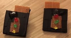
| + | The direction and the movement of the car controls the backlight. <br> | ||
| + | When the car is in drive or in reverse mode, the Green LED lights up. <br> | ||
| + | When the car is in stop mode, the Red LED lights up. <br> | ||
| + | When the car is steering to the right, the right indicator is lit, while when it is steering to the left, the left indicator is lit. | ||
| + | |||
| + | <br><br><br><br><br> | ||
| + | |||
| + | === Hardware Interface === | ||
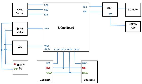
| + | In this section, you can describe how your hardware communicates, such as which BUSes used. You can discuss your driver implementation here, such that the '''Software Design''' section is isolated to talk about high level workings rather than inner working of your project. | ||
| + | |||
| + | '''Schematic''' | ||
| + | |||
| + | [[File: CmpE243_F16_Thunderbolt_Motor_HW_Interface.JPG|centre|600px|thumb|Motor IO Hardware interface]] | ||
| + | |||
| + | === Software Design === | ||
| + | |||
| + | ==== CAN Communication ==== | ||
| + | **'''''Drive, Steer and Speed signals from Master to Motor controller'''''<br> | ||
| + | BO_ 209 MASTER_DRIVING_CAR: 8 MASTER | ||
| + | SG_ MASTER_DRIVE_ENUM : 0|4@1+ (1,0) [0|0] "" MOTOR,COM_BRIDGE | ||
| + | SG_ MASTER_STEER_ENUM : 4|4@1+ (1,0) [0|0] "" MOTOR,COM_BRIDGE | ||
| + | SG_ MASTER_SPEED_ENUM : 8|4@1+ (1,0) [0|0] "" MOTOR,COM_BRIDGE | ||
| + | |||
| + | **'''''Speed and distance travelled data from Motor to Master and Communication bridge controllers'''''<br> | ||
| + | BO_ 147 MOTOR_CAR_SPEED: 4 MOTOR | ||
| + | SG_ MOTOR_SPEED_DATA_UNSIGNED : 0|8@1+ (1,0) [0|0] "" MASTER,COM_BRIDGE | ||
| + | SG_ MOTOR_DISTANCE_FROM_START_POINT_UNSIGNED : 8|8@1+ (1,0) [0|0] "meters" MASTER,COM_BRIDGE | ||
| + | |||
| + | **'''''Heartbeat signal from Motor to Master Controller'''''<br> | ||
| + | BO_ 339 MOTOR_HEARTBEAT: 2 MOTOR | ||
| + | SG_ MOTOR_HEARTBEAT_UNSIGNED : 0|11@1+ (1,0) [0|0] "" MASTER | ||
| + | |||
| + | ==== Algorithm ==== | ||
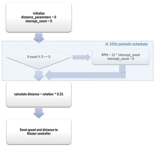
| + | '''Calculation of Speed''' | ||
| + | |||
| + | Below is the code snippet for calculation of speed in 10 Hz periodic callback function | ||
| + | |||
| + | <syntaxhighlight lang="c"> | ||
| + | if (!(count%5)) "every 500 ms | ||
| + | RPM_Speed=wheel_rotation_count * 12; | ||
| + | |||
| + | magnet_count+=wheel_rotation_count; | ||
| + | |||
| + | if (rcv_car.MASTER_DRIVE_ENUM != STOP) | ||
| + | { | ||
| + | Odometer = (magnet_count/10) * 0.31; | ||
| + | } | ||
| + | |||
| + | LD.setNumber(((int)RPM_Speed)% 100); | ||
| + | wheel_rotation_count = 0; | ||
| + | </syntaxhighlight> | ||
| + | |||
| + | === Implementation === | ||
| + | |||
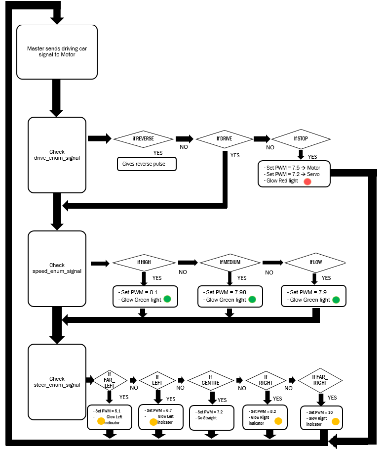
| + | Three signals - Drive, Speed and Steer signals are received by the Motor Controller from the Master. | ||
| + | Based on the signals received from the Master module, the motor is controlled. <br> | ||
| + | |||
| + | {| class="wikitable" | ||
| + | |- | ||
| + | ! scope="col"| Sr No. | ||
| + | ! scope="col"| Enum Signal name | ||
| + | ! scope="col"| Signal from Master to Motor | ||
| + | ! scope="col"| Motor Algorithm | ||
| + | ! scope="col"| Functionality | ||
| + | |- | ||
| + | |- | ||
| + | ! scope="row"| 1 | ||
| + | | Drive Signal | ||
| | | | ||
| − | * | + | * 1- Reverse |
| − | + | * 2- Stop | |
| − | * | + | * 3- Drive |
| | | | ||
| + | * 1- Send Reverse pulse and Check speed signal from Master | ||
| + | * 2- Set PWM = 7.5 for DC motor, PWM = 7.2 for Servo motor | ||
| + | * 3- Check speed signal from Master | ||
| | | | ||
| + | * 1- Drive in backward direction | ||
| + | * 2- Stop | ||
| + | * 3- Drive in forward direction | ||
|- | |- | ||
| − | ! scope="row"| | + | ! scope="row"| 2 |
| − | | | + | |Speed Signal |
| | | | ||
| − | * | + | * Low |
| − | * | + | * Medium |
| − | + | * High | |
| − | * | ||
| | | | ||
| + | * Set PWM = 7.9 | ||
| + | * Set PWM = 7.98 | ||
| + | * Set PWM = 8.1 | ||
| | | | ||
| + | Speed of the car | ||
|- | |- | ||
| − | ! scope="row"| | + | ! scope="row"| 3 |
| − | | | + | |Steer Signal |
| | | | ||
| − | * | + | * Far-left |
| − | * | + | * Left |
| − | + | * Center | |
| − | * | + | * Right |
| + | * Far-right | ||
| | | | ||
| + | * Set PWM of Servo motor = 5.1 | ||
| + | * Set PWM of Servo motor = 6.7 | ||
| + | * Set PWM of Servo motor = 7.2 | ||
| + | * Set PWM of Servo motor = 8.2 | ||
| + | * Set PWM of Servo motor = 10 | ||
| | | | ||
| + | Direction of the car | ||
| + | |- | ||
| + | |} | ||
| + | |||
| + | ''' Master-Motor IO Interface ''' | ||
| + | |||
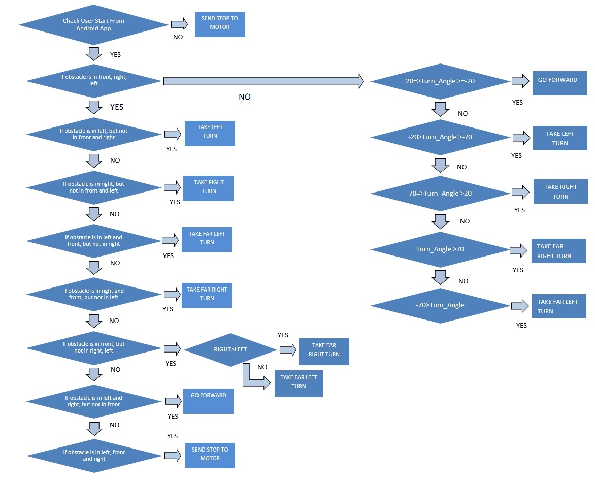
| + | [[File:CmpE243_F16_Thunderbolt_Master_Motor_IO_Interface.png|center|800px|800px|thumb|Master Motor Control]] | ||
| + | |||
| + | |||
| + | ''' Calculation of Speed and Distance ''' | ||
| + | [[File:CmpE243_F16_Thunderbolt_Motor-IO_calculation.JPG|center|500px|thumb|Calculation of Speed and Distance]] | ||
| + | |||
| + | === Testing & Technical Challenges === | ||
| + | |||
| + | 1. Ideally at 7.5% duty cycle PWM, the servo motor should be aligned to center position, but due to faulty hardware the servo motor is inclined towards right giving us wrong movement.<br> | ||
| + | We solved this problem by setting the PWM to 7.2% duty cycle during initialization, which resulted in accurate center position | ||
| + | |||
| + | 2. For D.C motor to start running, we have to initialize the ESC. Hence without providing 1.5ms pulse at the beginning, the motor will start running. | ||
| + | |||
| + | 3. As the battery voltage decreases, the motor does not run at the same speed with the same PWM. Hence with the decrease in speed we increased the PWM pulse linearly | ||
| + | |||
| + | 4. In order to run the motor in reverse direction (when the motor is currently running in the forward direction), it was required to apply reverse pulse, then a stop pulse and again a reverse pulse, back to back. | ||
| + | |||
| + | == Geographical Controller == | ||
| + | |||
| + | ==== Group Members ==== | ||
| + | * '''Samiksha Ambekar''' | ||
| + | * '''Virginia Menezes''' | ||
| + | |||
| + | === Schedule === | ||
| + | |||
| + | {| class="wikitable" | ||
|- | |- | ||
| − | ! scope="row"| | + | ! scope="col"| Sr No |
| − | | | + | ! scope="col"| Start Date |
| + | ! scope="col"| End Date | ||
| + | ! scope="col"| Task | ||
| + | ! scope="col"| Status | ||
| + | ! scope="col"| Actual Completed Date | ||
| + | |- | ||
| + | ! scope="row"| 1 | ||
| + | | 09/14/2016 | ||
| + | | 09/20/2016 | ||
| | | | ||
| − | * | + | * Study previous reports to research which components to order |
| + | | Completed | ||
| + | | 09/20/2016 | ||
| + | |- | ||
| + | ! scope="row"| 2 | ||
| + | | 09/21/2016 | ||
| + | | 09/27/2016 | ||
| | | | ||
| − | * | + | * Git and wiki report setup |
| + | | Completed | ||
| + | | 09/27/2016 | ||
| + | |- | ||
| + | ! scope="row"| 3 | ||
| + | | 09/28/2016 | ||
| + | | 10/04/2016 | ||
| | | | ||
| + | * Order GPS module, Compass and antenna | ||
| + | | Completed | ||
| + | | 10/04/2016 | ||
| + | |- | ||
| + | ! scope="row"| 4 | ||
| + | | 10/05/2016 | ||
| + | | 10/11/2016 | ||
| + | | | ||
| + | * Follow-up on ordered parts | ||
| + | | Completed | ||
| + | | 10/11/2016 | ||
| + | |- | ||
| + | ! scope="row"| 5 | ||
| + | | 10/12/2016 | ||
| + | | 10/18/2016 | ||
| + | | | ||
| + | * Developing the DBC File format for signals between GEO controller and Master, Android app and IO | ||
| + | | Completed | ||
| + | | 10/18/2016 | ||
| + | |- | ||
| + | ! scope="row"| 6 | ||
| + | | 10/19/2016 | ||
| + | | 10/25/2016 | ||
| + | | | ||
| + | * Interface the compass module to SJOne board using I2C communication | ||
| + | | Completed | ||
| + | | 10/20/2016 | ||
| + | |- | ||
| + | ! scope="row"| 7 | ||
| + | | 10/26/2016 | ||
| + | | 11/01/2016 | ||
| + | | | ||
| + | * Develop the algorithms for distance and turn angle calculation | ||
| + | * Interfacing of GEO controller with Master | ||
| + | | Completed | ||
| + | | 10/31/2016 | ||
| + | |- | ||
| + | ! scope="row"| 8 | ||
| + | | 11/02/2016 | ||
| + | | 11/08/2016 | ||
| + | | | ||
| + | * Calibrate the compass module and testing | ||
| + | | Completed | ||
| + | | 11/07/2016 | ||
| + | |- | ||
| + | ! scope="row"| 9 | ||
| + | | 11/09/2016 | ||
| + | | 11/15/2016 | ||
| | | | ||
| + | * Interface GPS module to SJOne board using UART communication | ||
| + | * Calibrating the GPS and testing | ||
| + | | Completed | ||
| + | | 11/13/2016 | ||
| + | |- | ||
| + | ! scope="row"| 10 | ||
| + | | 11/16/2016 | ||
| + | | 11/22/2016 | ||
| + | | | ||
| + | * Integrating of GPS and compass module | ||
| + | * Interfacing of GEO controller with Android | ||
| + | | Completed | ||
| + | | 11/20/2016 | ||
| + | |- | ||
| + | ! scope="row"| 11 | ||
| + | | 11/23/2016 | ||
| + | | 11/29/2016 | ||
| + | | | ||
| + | * Interfacing of GEO controller with LCD | ||
| + | * Unit Testing of GEO controller and bug fixes and re-calibrate if needed. | ||
| + | | Completed | ||
| + | | 11/29/2016 | ||
| + | |- | ||
| + | ! scope="row"| 12 | ||
| + | | 11/30/2016 | ||
| + | | 12/06/2016 | ||
| + | | | ||
| + | * Testing of GEO controller with other modules and re-calibration, if required | | ||
| + | | Completed | ||
| + | | 12/06/2016 | ||
| + | |- | ||
| + | ! scope="row"| 13 | ||
| + | | 12/07/2016 | ||
| + | | 12/13/2016 | ||
| + | | | ||
| + | * Final Testing | ||
| + | | Completed | ||
| + | | 12/17/2016 | ||
|- | |- | ||
|} | |} | ||
=== Design & Implementation === | === Design & Implementation === | ||
| − | The | + | The Geographical Controller is used to track the current location of the car and the turn angle to steer to the next checkpoint. |
| + | |||
| + | The module comprises of a GPS module and a compass. | ||
| + | |||
| + | Once the user choses the destination point on the Android application, the app will map the shortest path available from the current location to the destination and plot multiple checkpoints based on that. | ||
| + | The coordinates of these checkpoints are sent to the GEO controller, which will calculate the distance between the current location of the car and the next checkpoint and the turn angle required to reach the next checkpoint and send this information to the Master controller. | ||
=== Hardware Design === | === Hardware Design === | ||
| − | + | ||
| + | The GPS module used is ''SparkFun Venus GPS with SMA Connector'' [https://www.sparkfun.com/products/11058]. | ||
| + | And the Compass is ''CMPS11 - Tilt Compensated Compass Module'' [https://acroname.com/products/r375-cmps11?sku=R375-CMPS11]. | ||
| + | |||
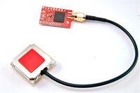
| + | ==== GPS Module ==== | ||
| + | |||
| + | [[File:CmpE243_F16_Thunderbolt_GPS_Module.jpg|200px|left|thumb|GPS Module]] | ||
| + | [[File:CmpE243_F16_Thunderbolt_SkyTraq_GPS_Viewer.JPG|right|500px|thumb|SkyTraq GPS Viewer]] | ||
| + | [[File:CmpE243_F16_Thunderbolt_GPS_Module_with_antenna.jpg|left|200px|thumb|GPS with antenna ]] | ||
| + | |||
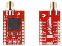
| + | The GPS Module we use in our project is ''SparkFun Venus GPS with SMA Connector'' based on ''Venus638FLPx IC''. | ||
| + | |||
| + | There are three modes of operation based on how it is powered: | ||
| + | |||
| + | 1. Cold start: If no external battery (VBAT) of 3V is connected to the module, it will take a longer time to start and get a fix. | ||
| + | |||
| + | 2. Hot start: When VBAT is connected to the module, even if the GPS is turned off and turned on within a certain time, it will get its fix from the value stored in memory. | ||
| + | |||
| + | 3. Warm start: If the GPS is not turned on within the time frame for hot start (typically 2 hours), it will take sometime to get satellite fix. | ||
| + | |||
| + | |||
| + | '''GPS Configuration''' | ||
| + | |||
| + | The GPS module sends out the information in standard NMEA-0183 format or SkyTraq Binary sentence format. | ||
| + | The default rate is 9600 bps and is configurable up to 115200 bps. | ||
| + | The update rate of this GPS module is up to 20Hz. This indicates how often it recalculates and reports its position. | ||
| + | |||
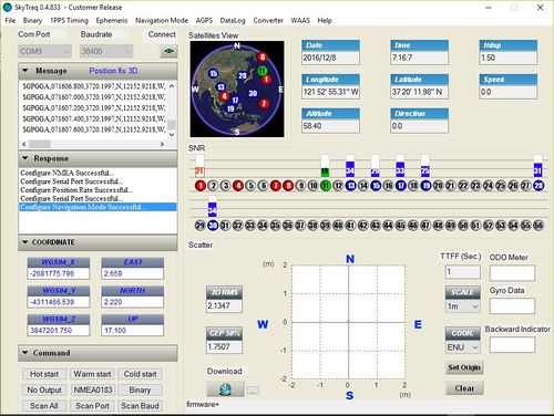
| + | We have configured the GPS module using the GPS Viewer software provided by Skytraq. | ||
| + | |||
| + | 1. The rate of UART is set at 38400bps | ||
| + | |||
| + | 2. Update rate of 5Hz | ||
| + | |||
| + | 3. Also it is possible to choose which NMEA message format we want the data in. For our car, we are using the GPGGA (Global Positioning System Fix Data) message format. | ||
| + | |||
| + | Apart from configuration, all other information like data received from the GPS, if fix position, no. of satellites, latitude and longitude etc. all can be viewed through this software. | ||
| + | <br><br><br> | ||
| + | |||
| + | |||
| + | GGA Message Structure : '''''$GPGGA,hhmmss.sss,ddmm.mmmm,a,dddmm.mmmm,a,x,xx,x.x,x.x,M,,,,xxxx*hh<CR><LF>''''' | ||
| + | |||
| + | Example data: '''''$GPGGA,120218.899,2400.0000,N,12100.0000,E,0,00,0.0,0.0,M,0.0,M,,0000*69''''' | ||
| + | |||
| + | where, | ||
| + | $GPGGA -- Global Positioning System Fix Data (Sentence Identifier) | ||
| + | 120218.899 -- UTC Time of position in hhmmss.sss format | ||
| + | 2400.0000 -- Latitude in ddmm.mmmm format | ||
| + | N -- Latitude hemisphere indicator, ‘N’ = North, ‘S’ = South | ||
| + | 12100.0000 -- Longitude in dddmm.mmmm format | ||
| + | E -- E/W Indicator | ||
| + | 0 -- GPS quality indicator | ||
| + | 0: position fix unavailable | ||
| + | 1: valid position fix, SPS mode | ||
| + | 2: valid position fix, differential GPS mode | ||
| + | 3: GPS PPS Mode, fix valid | ||
| + | 4: Real Time Kinematic. System used in RTK mode with fixed integers | ||
| + | 5: Float RTK. Satellite system used in RTK mode. Floating integers | ||
| + | 6: Estimated (dead reckoning) Mode | ||
| + | 7: Manual Input Mode | ||
| + | 8: Simulator Mode | ||
| + | 00 -- Number of satellites in use (00~12) | ||
| + | 0.0 -- HDOP (Horizontal dilution of precision), (00.0 ~ 99.9) | ||
| + | 0.0,M -- Altitude in Meters - above mean sea level, (-9999.9 ~ 17999.9) | ||
| + | 0.0,M -- Height of geoid above WGS84 ellipsoid (mean sea level), (-9999.9 ~ 17999.9) | ||
| + | 0000 -- DGPS Station ID - Differential reference station ID, 0000 ~ 1023 | ||
| + | NULL when DGPS not used | ||
| + | *69 -- Checksum (begins with *)''' | ||
| + | |||
| + | ==== Compass Module ==== | ||
| + | |||
| + | [[File: CmpE243_F16_Thunderbolt_Compass_Module.JPG|left|220px|thumb|Compass Module ]] | ||
| + | [[File: CmpE243_F16_Thunderbolt_Compass_Module_mode_selection.JPG|right|420px|thumb|Modes of operation ]] | ||
| + | |||
| + | |||
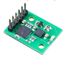
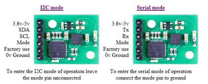
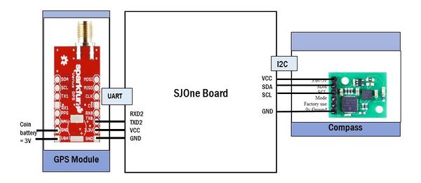
| + | The Compass Module we use in our project is ''CMPS11 - Tilt Compensated Compass Module''. <br> It employs a 3-axis magnetometer, 3-axis gyro and a 3-axis accelerometer. A Kalman filter is used to combine the gyro and accelerometer to remove the errors caused by tilting of the PCB. The output of the three sensors measuring x, y and z components of the magnetic field, together with the pitch and roll are used to calculate the bearing. It requires a power supply of 3.6-5V. The module can be operated in two modes - serial or I2C. We have interfaced the CMPS11 module with SJOne board via I2C for communication.<br><br> | ||
| + | |||
| + | '''Compass calibration''' <br> | ||
| + | The calibration of the compass is very important. We mounted the compass on the car with the motor working to take into account the magnetic deviation caused by its EMI. Calibration mode is entered by sending a 3 byte sequence of 0xF0,0xF5 and 0xF6 to the command register in 3 separate I2C frames with a delay of 20ms between them. Once the CMPS11 is in calibration mode, the LED will start blinking. It should now be rotated in all directions in 3 dimensions. Once calibrated successfully, the calibration mode can be exited with command of 0xF8. | ||
| + | <br><br><br> | ||
=== Hardware Interface === | === Hardware Interface === | ||
| − | + | ||
| + | '''Schematic''' | ||
| + | |||
| + | [[File:CmpE243_F16_Thunderbolt_GEO_HW_Interface.JPG|centre|600px|thumb|Hardware interface]] | ||
=== Software Design === | === Software Design === | ||
| − | + | ==== Algorithm ==== | |
| + | '''Distance Calculation''' | ||
| + | |||
| + | We are using Haversine formula to calculate the great-circle distance between two checkpoints – that is, the shortest distance over the earth’s surface | ||
| + | |||
| + | '''Distance''' = R ⋅ c | ||
| + | c = 2 ⋅ atan2(√a, √(1−a)) | ||
| + | a = sin²(Δφ/2) + cos φ1 ⋅ cos φ2 ⋅ sin²(Δλ/2) | ||
| + | |||
| + | where, | ||
| + | φ is latitude, | ||
| + | λ is longitude, | ||
| + | R is earth’s radius (mean radius = 6,371km), | ||
| + | |||
| + | Note: Angles need to be in radians to pass to trignometric functions | ||
| + | |||
| + | '''Bearing''' | ||
| + | |||
| + | The final heading will differ from the initial heading by varying degrees according to distance and latitude. This can be calculated as follows: | ||
| + | |||
| + | '''Bearing''' (θ)(radians) = atan2(sin Δλ ⋅ cos φ2 , cos φ1 ⋅ sin φ2 − sin φ1 ⋅ cos φ2 ⋅ cos Δλ) | ||
| + | |||
| + | where, | ||
| + | φ1,λ1 is the start point, | ||
| + | φ2,λ2 the end point | ||
| + | Δλ is the difference in longitude | ||
| + | |||
| + | ====CAN Communication==== | ||
| + | |||
| + | Following table lists the signals sent by GPS to other controllers via CAN. | ||
| + | |||
| + | {| class="wikitable" | ||
| + | |+ GEO Controller Communication Table | ||
| + | |- | ||
| + | ! scope="col"| Sr. No. | ||
| + | ! scope="col"| Message Number | ||
| + | ! scope="col" width=350px| Destination | ||
| + | ! scope="col"| Message Name (MSG_FUNCTION) | ||
| + | ! scope="col"| Data Layout of Data Sent over CAN (byte[0] = total number of data bytes) | ||
| + | |- | ||
| + | ! scope="col"| 1 | ||
| + | | 0x290 | ||
| + | | Communication Bridge and I/O | ||
| + | | GPS_ACKNOWLEDGEMENT | ||
| + | | | ||
| + | - | ||
| + | |- | ||
| + | ! scope="col"| 2 | ||
| + | | 0x162 | ||
| + | | Communication Bridge and I/O | ||
| + | | CURRENT_LOCATION | ||
| + | | | ||
| + | Msg : 30 bits : GPS_latitude | ||
| + | Msg : 30 bits : GPS_longitude | ||
| + | |- | ||
| + | ! scope="col"| 3 | ||
| + | | 0x338 | ||
| + | | Master | ||
| + | | GPS_HEARTBEAT | ||
| + | | | ||
| + | - | ||
| + | |- | ||
| + | ! scope="col"| 4 | ||
| + | | 0x146 | ||
| + | | Master and Motor IO | ||
| + | | GPS_MASTER_DATA | ||
| + | | | ||
| + | Msg : 16 bits : turn angle | ||
| + | Msg : 1 bit : isFinal | ||
| + | Msg : 16 bits : distance to final destination | ||
| + | Msg : 16 bits : distance to next checkpoint | ||
| + | |- | ||
| + | ! scope="col"| 5 | ||
| + | | 0x338 | ||
| + | | Communication Bridge and I/O | ||
| + | | GPS_COMPASS_HEADING | ||
| + | | | ||
| + | - | ||
| + | |- | ||
| + | |} | ||
| + | |||
| + | |||
| + | The following are the signals that are received or sent by the GEO Controller. | ||
| + | |||
| + | '''''**Receive Checkpoints from Communication Bridge (Total number of checkpoints, current checkpoint number, latitude and longitude'''''<br> | ||
| + | BO_ 148 COM_BRIDGE_CHECK_POINT: 8 COM_BRIDGE | ||
| + | SG_ COM_BRIDGE_MUX M : 0|2@1+ (1,0) [0|0] "" GPS | ||
| + | SG_ COM_BRIDGE_TOTAL_COUNT_UNSIGNED : 2|8@1+ (1,0) [0|0] "" GPS | ||
| + | SG_ COM_BRIDGE_CURRENT_COUNT_UNSIGNED : 10|8@1+ (1,0) [0|0] "count" GPS | ||
| + | SG_ COM_BRIDGE_LATTITUDE_SIGNED m0 : 18|40@1+ (0.000001,-90) [-90|90] "degrees" GPS | ||
| + | SG_ COM_BRIDGE_LONGITUDE_SIGNED m1 : 18|40@1+ (0.000001,-180) [-180|180] "degrees" GPS | ||
| + | |||
| + | '''''**Receive RESET signal from Com Bridge (Android device)'''''<br> | ||
| + | BO_ 10 COM_BRIDGE_RESET: 2 COM_BRIDGE | ||
| + | SG_ COM_BRIDGE_RESET_UNSIGNED : 0|11@1+ (1,0) [0|0] "" MASTER,GPS,MOTOR,SENSOR | ||
| + | |||
| + | '''''**Receive START signal from Com Bridge (Android device)'''''<br> | ||
| + | BO_ 84 COM_BRIDGE_CLICKED_START: 2 COM_BRIDGE | ||
| + | SG_ COM_BRIDGE_CLICKED_START_UNSIGNED : 0|11@1+ (1,0) [0|0] "" MASTER,GPS | ||
| + | |||
| + | '''''**Send acknowledgement to Com Bridge if all checkpoints have been received'''''<br> | ||
| + | BO_ 290 GPS_ACKNOWLEDGEMENT: 2 GPS | ||
| + | SG_ GPS_ACKNOWLEDGEMENT_UNSIGNED : 0|11@1+ (1,0) [0|0] "" COM_BRIDGE | ||
| + | |||
| + | '''''**Send current location coordinates (latitude and longitude in decimal degrees) to Com Bridge'''''<br> | ||
| + | BO_ 162 GPS_CURRENT_LOCATION: 8 GPS | ||
| + | SG_ GPS_LATTITUDE_SIGNED : 0|30@1+ (0.000001,-90) [-90|90] "degrees" COM_BRIDGE | ||
| + | SG_ GPS_LONGITUDE_SIGNED : 30|30@1+ (0.000001,-180) [-180|180] "degrees" COM_BRIDGE | ||
| + | |||
| + | '''''**Send Heartbeat signal to Master'''''<br> | ||
| + | BO_ 338 GPS_HEARTBEAT: 2 GPS | ||
| + | SG_ GPS_HEARTBEAT_UNSIGNED : 0|11@1+ (1,0) [0|0] "" MASTER | ||
| + | |||
| + | '''''**Send calculated data to Master and motor (Turn angle, Is final, distance to final destination, distance to next checkpoint'''''<br> | ||
| + | BO_ 146 GPS_MASTER_DATA: 7 GPS | ||
| + | SG_ GEO_DATA_TURNANGLE_SIGNED : 0|16@1+ (0.1,-180) [-180|180] "degrees" MASTER,MOTOR | ||
| + | SG_ GEO_DATA_ISFINAL_SIGNED : 16|1@1+ (1,0) [0|0] "" MASTER,MOTOR | ||
| + | SG_ GEO_DATA_DISTANCE_TO_FINAL_DESTINATION_SIGNED : 17|16@1+ (0.1,0) [0|0] "meters" MASTER,MOTOR | ||
| + | SG_ GEO_DATA_DISTANCE_TO_NEXT_CHECKPOINT_SIGNED : 33|16@1+ (0.01,0) [0|0] "meters" MASTER,MOTOR | ||
| + | |||
| + | '''''**Send Compass reading to Com Bridge'''''<br> | ||
| + | BO_ 300 GPS_COMPASS_HEADING: 3 GPS | ||
| + | SG_ GEO_DATA_COMPASS_HEADING_UNSIGNED : 0|16@1+ (0.1,0) [0|359] "degrees" COM_BRIDGE | ||
| + | |||
| + | '''''**Receive Acknowledgement from Master when data is received successfully'''''<br> | ||
| + | BO_ 281 MASTER_ACKNOWLEDGEMENT: 2 MASTER | ||
| + | SG_ ACKNOWLEDGEMENT_DATA_REACHED_UNSIGNED : 0|11@1+ (1,0) [0|0] "" GPS | ||
=== Implementation === | === Implementation === | ||
| − | + | ||
| + | * '''In 1 Hz Periodic callback function''' | ||
| + | ** Send Heartbeat signal to Master | ||
| + | ** Reset CAN Bus if Bus off | ||
| + | ** Send Compass Reading to Communication bridge controller | ||
| + | <br> | ||
| + | * '''In 10 Hz Periodic callback function''' | ||
| + | ** Get Compass reading | ||
| + | ** Calibrate compass if Switch 1 pressed or Reset compass to factory settings if Switch 2 is pressed | ||
| + | ** Receive location from GPS module via UART communication at 38400 baud rate at 5 Hz update rate | ||
| + | ** Parse the received string from GPS module to extract latitude and longitude coordinates | ||
| + | ** Convert latitude and longitude to decimal degrees | ||
| + | ** Send Current Location to Communication bridge controller | ||
| + | ** Calculate distance to next checkpoint and final destination and turn angle and set is_final flag and Send to Master Controller | ||
| + | ** Display Checkpoint number reached on Seven Segment display of SJONE board | ||
| + | |||
| + | <br> | ||
| + | * '''In 100 Hz Periodic Callback function''' | ||
| + | ** Receive and save checkpoints from Communication bridge controller | ||
| + | ** Receive reset signal from Com bridge and reset SJOne board | ||
| + | ** Send Acknowledgment to Communication bridge controller if all checkpoints have been received | ||
| + | <br> | ||
| + | [[File: CmpE243_F16_Thunderbolt_GEO_Flow_diagram.JPG|center|800px|thumb|Geographical Controller Flow Diagram]] | ||
=== Testing & Technical Challenges === | === Testing & Technical Challenges === | ||
| − | + | ||
| − | + | [[File:CmpE243_F16_Thunderbolt_GEO_Problem1.jpg|200px|left|thumb|GPS gives imprecise current location]] | |
| + | |||
| + | |||
| + | 1. '''Unable to get a satellite fix on GPS module''': <br> The first GPS module we received would not get a satellite fix. We spent a considerable amount of time outdoors to get a fix but it never did. <br> Finally we returned the product and ordered a new one. We got a feedback from the vendor ''Sparkfun'' that the GPS module was defective and so the issue. <br> The new module got a fix the first time within the first 20 minutes. | ||
| + | <br><br> | ||
| + | |||
| + | 2. '''GPS gives imprecise current location''': <br> There was a small yet noticeable difference between the location provided by the GPS module and the exact current location. The adjacent image shows a plot of the current location vs the route plotted. <br> We tried to fix this by increasing the update rate from 5Hz to 10Hz, but this failed the parsing of the data and we sometimes ended up getting incorrect latitude and longitude values. <br> Finally we configured the GPS module to pedestrian mode which gave precise current location. | ||
| + | <br><br> | ||
| + | |||
| + | 3. '''Car not stopping at final destination''':<br> As per our algorithm, once the car reaches the destination, the ''IS_FINAL'' flag should be set and the Master controller should send the ''STOP'' command to the motor controller. <br> But it is not possible that the car reaches the exact location i.e. achieves the exact coordinates in precision and so the ''IS_FINAL'' flag was never set, resulting the car never stopping even on reaching the final destination. <br> To fix this issue, we modified the algorithm that when the distance between the car and the final destination is between 3 meters, the ''IS_FINAL'' flag would be set, and thus the Master controller will send out ''STOP'' command, bringing the car to a halt. | ||
| + | |||
| + | <br><br><br><br><br><br> | ||
| + | |||
| + | == Android and Communication Bridge Controller == | ||
| + | ==== Group Members ==== | ||
| + | * '''Nikhil Namjoshi''' | ||
| + | |||
| + | === Schedule === | ||
| + | {| class="wikitable" | ||
| + | |- | ||
| + | ! scope="col"| Sr No | ||
| + | ! scope="col"| Start Date | ||
| + | ! scope="col"| End Date | ||
| + | ! scope="col"| Task | ||
| + | ! scope="col"| Status | ||
| + | ! scope="col"| Actual Completed Date | ||
| + | |- | ||
| + | ! scope="row"| 1 | ||
| + | | 9/27/2016 | ||
| + | | 10/4/2016 | ||
| + | | | ||
| + | * Decide the Bluetooth module and purchase it.<br> | ||
| + | * Search online and read previous projects wikipedia pages. | ||
| + | | Completed | ||
| + | | 10/4/2016 | ||
| + | |- | ||
| + | ! scope="row"| 2 | ||
| + | | 10/6/2016 | ||
| + | | 10/8/2016 | ||
| + | | | ||
| + | * Testing of Bluetooth Module with SJ-One Board using available bluetooth app on Android app store | ||
| + | | Completed | ||
| + | | 10/8/2016 | ||
| + | |- | ||
| + | ! scope="row"| 3 | ||
| + | | 9/30/2016 | ||
| + | | 10/2/2016 | ||
| + | | | ||
| + | * Development of basic android app for one directional bluetooth communication. | ||
| + | | Completed | ||
| + | | 10/2/2016 | ||
| + | |- | ||
| + | ! scope="row"| 4 | ||
| + | | 10/2/2016 | ||
| + | | 10/6/2016 | ||
| + | | | ||
| + | * Development of basic android app for plotting Google Map route between two points. | ||
| + | | Completed | ||
| + | | 10/6/2016 | ||
| + | |- | ||
| + | ! scope="row"| 5 | ||
| + | | 10/10/2016 | ||
| + | | 10/25/2016 | ||
| + | | | ||
| + | * Bi-directional communication between SJ-ONE Board and Android App. | ||
| + | | Completed | ||
| + | | 10/25/2016 | ||
| + | |- | ||
| + | ! scope="row"| 6 | ||
| + | | 10/25/2016 | ||
| + | | 11/2/2016 | ||
| + | | | ||
| + | * Interface android module with CAN | ||
| + | | Completed | ||
| + | | 10/31/2016 | ||
| + | |- | ||
| + | ! scope="row"| 7 | ||
| + | | 11/3/2016 | ||
| + | | 11/11/2016 | ||
| + | | | ||
| + | * Interfacing with GPS module using CAN bus for receiving current location. | ||
| + | | Completed | ||
| + | | 11/11/2016 | ||
| + | |- | ||
| + | ! scope="row"| 8 | ||
| + | | 11/12/2016 | ||
| + | | 11/23/2016 | ||
| + | | | ||
| + | * Integration with Master through CAN bus. | ||
| + | | Completed | ||
| + | | 11/25/2016 | ||
| + | |- | ||
| + | ! scope="row"| 9 | ||
| + | | 11/26/2016 | ||
| + | | 12/5/2016 | ||
| + | | | ||
| + | * Android App GUI enhancements and bug fixes. | ||
| + | | Completed | ||
| + | | 12/10/2016 | ||
| + | |- | ||
| + | |} | ||
=== Design & Implementation === | === Design & Implementation === | ||
| − | The | + | An Android application is designed to control the RC car to help it navigate from the source to the destination and display useful information on it. The Communication Bridge Controller is responsible to connect the RC car to the Android application via Bluetooth. It provides the route information between source and destination chosen on the Android application. Once the source and destination is chosen, checkpoints between the two are fixed on the Google Maps and sent to the geographical controller. The checkpoints and destination information is then used by the Geographical controller to calculate the distance and turn angle the car has to travel for based on the current location and sent to the Master controller. |
| + | |||
| + | HC-06 Bluetooth Module[edit] | ||
=== Hardware Design === | === Hardware Design === | ||
| − | + | '''Bluetooth Module''' | |
| + | |||
| + | [[File:CmpE243 F16 Thunderbolt BT HC05.JPG|left|330px|thumb|Bluetooth HC-05 Module]] | ||
| + | <br> | ||
| + | We are using Bluetooth module HC-05 to establish wireless communication between the car and the Android device. <br> | ||
| + | This module is based on the Cambridge Silicon Radio BC417 2.4 GHz BlueTooth Radio chip. This is a complex chip which uses an external 8 Mbit flash memory <br> | ||
| + | It includes the Radio and Memory chips, 26 MHz crystal, antenna and RF matching network. <br> | ||
| + | The right section of the Bluetooth Board has connection pins for power and signals as well as a 5V to 3.3V Regulator, LED, and level shifting. | ||
| + | <br><br> | ||
| + | |||
| + | '''HC-05 PinOut''' : <br><br> | ||
| + | - KEY: If brought HIGH before power is applied, forces AT Command Setup Mode. LED blinks slowly (2 seconds) <br> | ||
| + | - VCC: +5V Power <br> | ||
| + | - GND: Ground <br> | ||
| + | - TXD: Transmit Serial Data from HC-05 to SJOne board UART RXD <br> | ||
| + | - RXD: Receive Serial Data from SJOne board UART TXD <br> | ||
| + | - STATE: Tells if connected or not <br> | ||
| + | |||
| + | <br><br><br><br> | ||
=== Hardware Interface === | === Hardware Interface === | ||
| − | + | ||
| + | |||
| + | [[File: CmpE243_F16_Thunderbolt_Com_Bridge_Block_Diagram.JPG |600px|left|thumb|Communication Bridge Hardware Interface]] | ||
| + | {| class="wikitable" | ||
| + | |- | ||
| + | ! scope="col"| Sr.No | ||
| + | ! scope="col"| SJOne Pin Number | ||
| + | ! scope="col"| Bluetooth Pin Function | ||
| + | |||
| + | |- | ||
| + | ! scope="row"| 1 | ||
| + | | TXD3 | ||
| + | | RXD | ||
| + | |||
| + | |- | ||
| + | ! scope="row"| 2 | ||
| + | | RXD3 | ||
| + | | TXD | ||
| + | |||
| + | |- | ||
| + | ! scope="row"| 3 | ||
| + | | VCC | ||
| + | | Bluetooth VCC | ||
| + | |||
| + | |- | ||
| + | ! scope="row"| 4 | ||
| + | | GND | ||
| + | | Bluetooth GND | ||
| + | |- | ||
| + | |} | ||
| + | <br><br><br><br><br><br><br> | ||
=== Software Design === | === Software Design === | ||
| − | + | ||
| + | ==== Android Application Design ==== | ||
| + | <br> | ||
| + | The Android application is built to let the user control the RC car to navigate it between the current location and the destination. The App lets the user select the destination and then chooses the shortest path available between the current location up to the destination. <br> It plots checkpoints between the two locations and sends it to the Geographical controller, which calculates the distance and turn angle between the current location and the next checkpoint and send to the Master which controls the motor controller. <br><br> | ||
| + | |||
| + | Below are the buttons on the Android application that are available to the User | ||
| + | * '''ACTIVATE BLUETOOTH''' - User is prompted to Turn on Bluetooth on the phone. User can "allow" or "deny" the request | ||
| + | * '''DEACTIVATE BLUETOOTH''' - User can disable the Bluetooth | ||
| + | * '''CONNECT TO THUNDERBOLT''' - The device Bluetooth is paired with the Bluetooth module HC-05 on the car | ||
| + | * '''GOOGLE MAPS''' - The current car location is visible on the app and the User can select the destination | ||
| + | * '''START''' - Sends START signal to all controllers and sends the checkpoints to the GPS controller | ||
| + | * '''STOP ''' - Sends STOP Signal to all controllers | ||
| + | * '''RESET''' - Sends reset signal to all the controllers and all the SJOne boards are reset | ||
| + | <br> | ||
| + | {| | ||
| + | |[[File:CmpE243 F16 Thunderbolt AndroidAppIcon.png|left|200px|thumb|Android App Icon]] | ||
| + | |[[File:CmpE243 F16 Thunderbolt WhenBluetoothis OFF.png|left|200px|thumb|Application Homepage]] | ||
| + | |[[File:CmpE243_F16_Thunderbolt_PermissiontoTurnOnBluetooth.png|left|200px|thumb|Permission to turn ON Bluetooth]] | ||
| + | |[[File:CmpE243 F16 Thunderbolt PopupIndicatingBluetoothOn.png|center|200px|thumb|Android App connected to Bluetooth]] | ||
| + | |} | ||
| + | {| | ||
| + | |[[File:CmpE243_F16_Thunderbolt_PopupIndicatingConnectedStatus.png|right|200px|thumb| Android App online status]] | ||
| + | |[[File:CmpE243_F16_Thunderbolt_AppDisconnected.jpg|right|200px|thumb| When connection between App and Bluetooth Controller is lost]] | ||
| + | |[[File:CmpE243 F16 Thunderbolt CurrentLocationMarker.png|200px|thumb|right| Current Location Marker]] | ||
| + | |[[File:CmpE243 F16 Thunderbolt Route.png|200px|thumb|right| Route to the destination with multiple checkpoints]] | ||
| + | |} | ||
| + | |||
| + | '''Features of Android Application''' | ||
| + | |||
| + | * App maintains stable Bluetooth connection even when app goes in background . It is a useful feature since the app can be interrupted by a phone call and you don't want to do the connection process all over again. | ||
| + | |||
| + | * It checks if your phone's Bluetooth is enabled or not. If it is disabled, it provides you the option to enable it through the app itself. | ||
| + | |||
| + | * It allows you to go to google maps activity only when your device maintains connection with the Bluetooth HC - 05 module. If the connection is broken the app takes you back to first activity and will ask you to connect again. | ||
| + | |||
| + | * To use Google Maps it is important that you need internet connection in order to plot routes. Before you are taken to google maps activity, it will check if you are connected to Wi-Fi or mobile data. If you are not, it will display a dialog box which has settings options and on clicking that option you will be taken to settings so that you can turn on the WIFI or data. | ||
| + | |||
| + | * The app has start and stop button to give start and stop commands to the car. | ||
| + | |||
| + | * We have also implemented reset functionality with a reset button. Clicking this button will send reset signal to all the SJOne boards and will also reload the google maps activity. The importance of doing this is to reset the system so that the entire process can be started from the beginning. | ||
| + | |||
| + | * We are displaying useful information such as the compass reading, speed and distance on the app which is very helpful in debugging and testing. | ||
| + | |||
| + | <br> | ||
| + | |||
| + | ==== CAN Communication ==== | ||
| + | |||
| + | The following are the signals that are received or sent by the COM Bridge Controller. | ||
| + | |||
| + | **'''''Receive current location (latitude and longitude) from GEO Controller'''''<br> | ||
| + | BO_ 162 GPS_CURRENT_LOCATION: 8 GPS | ||
| + | SG_ GPS_LATTITUDE_SIGNED : 0|30@1+ (0.000001,-90) [-90|90] "degrees" COM_BRIDGE | ||
| + | SG_ GPS_LONGITUDE_SIGNED : 30|30@1+ (0.000001,-180) [-180|180] "degrees" COM_BRIDGE | ||
| + | |||
| + | **'''''Send START signal to Master and GEO Controller'''''<br> | ||
| + | BO_ 84 COM_BRIDGE_CLICKED_START: 2 COM_BRIDGE | ||
| + | SG_ COM_BRIDGE_CLICKED_START_UNSIGNED : 0|11@1+ (1,0) [0|0] "" MASTER,GPS | ||
| + | |||
| + | **'''''Send HEARTBEAT signal to Master'''''<br> | ||
| + | BO_ 340 COM_BRIDGE_HEARTBEAT: 2 COM_BRIDGE | ||
| + | SG_ COM_BRIDGE_HEARTBEAT_UNSIGNED : 0|11@1+ (1,0) [0|0] "" MASTER | ||
| + | |||
| + | **'''''Send STOP signal to Master'''''<br> | ||
| + | BO_ 4 COM_BRIDGE_STOPALL: 2 COM_BRIDGE | ||
| + | SG_ COM_BRIDGE_STOPALL_UNSIGNED : 0|11@1+ (1,0) [0|0] "" MASTER | ||
| + | |||
| + | **'''''Send RESET signal to Master'''''<br> | ||
| + | BO_ 3 COM_BRIDGE_RESET: 2 COM_BRIDGE | ||
| + | SG_ COM_BRIDGE_RESET_UNSIGNED : 0|11@1+ (1,0) [0|0] "" MASTER,GPS,MOTOR,SENSOR | ||
| + | |||
| + | **'''''Send Checkpoints information to GEO Controller (total checkpoints, current checkpoint number, checkpoint latitude and longitude)'''''<br> | ||
| + | BO_ 148 COM_BRIDGE_CHECK_POINT: 8 COM_BRIDGE | ||
| + | SG_ COM_BRIDGE_MUX M : 0|2@1+ (1,0) [0|0] "" GPS | ||
| + | SG_ COM_BRIDGE_TOTAL_COUNT_UNSIGNED : 2|8@1+ (1,0) [0|0] "" GPS | ||
| + | SG_ COM_BRIDGE_CURRENT_COUNT_UNSIGNED : 10|8@1+ (1,0) [0|0] "count" GPS | ||
| + | SG_ COM_BRIDGE_LATTITUDE_SIGNED m0 : 18|40@1+ (0.000001,-90) [-90|90] "degrees" GPS | ||
| + | SG_ COM_BRIDGE_LONGITUDE_SIGNED m1 : 18|40@1+ (0.000001,-180) [-180|180] "degrees" GPS | ||
| + | |||
| + | **'''''Receive Acknowledgement from GEO Controller'''''<br> | ||
| + | BO_ 290 GPS_ACKNOWLEDGEMENT: 2 GPS | ||
| + | SG_ GPS_ACKNOWLEDGEMENT_UNSIGNED : 0|11@1+ (1,0) [0|0] "" COM_BRIDGE | ||
| + | |||
| + | **'''''Receive Master car driving signal from GEO Controller''''' <br> | ||
| + | BO_ 209 MASTER_DRIVING_CAR: 8 MASTER | ||
| + | SG_ MASTER_DRIVE_ENUM : 0|4@1+ (1,0) [0|0] "" MOTOR,COM_BRIDGE | ||
| + | SG_ MASTER_STEER_ENUM : 4|4@1+ (1,0) [0|0] "" MOTOR,COM_BRIDGE | ||
| + | SG_ MASTER_SPEED_ENUM : 8|4@1+ (1,0) [0|0] "" MOTOR,COM_BRIDGE | ||
| + | |||
| + | **'''''Receive speed of car and distance travelled from the Motor Controller''''' <br> | ||
| + | BO_ 147 MOTOR_CAR_SPEED: 4 MOTOR | ||
| + | SG_ MOTOR_SPEED_DATA_UNSIGNED : 0|8@1+ (1,0) [0|0] "" MASTER,COM_BRIDGE | ||
| + | SG_ MOTOR_DISTANCE_FROM_START_POINT_UNSIGNED : 8|8@1+ (1,0) [0|0] "meters" MASTER,COM_BRIDGE | ||
| + | |||
| + | **'''''Receive left, right, front and back sensor values from the Sensor Controller''''' <br> | ||
| + | BO_ 144 SENSOR_SONARS: 8 SENSOR | ||
| + | SG_ SENSOR_SONARS_LEFT_UNSIGNED : 0|16@1+ (1,0) [0|0] "inches" MASTER,MOTOR,COM_BRIDGE | ||
| + | SG_ SENSOR_SONARS_RIGHT_UNSIGNED : 16|16@1+ (1,0) [0|0] "inches" MASTER,MOTOR,COM_BRIDGE | ||
| + | SG_ SENSOR_SONARS_FRONT_UNSIGNED : 32|16@1+ (1,0) [0|0] "inches" MASTER,MOTOR,COM_BRIDGE | ||
| + | SG_ SENSOR_SONARS_BACK_UNSIGNED : 48|16@1+ (1,0) [0|0] "inches" MASTER,MOTOR,COM_BRIDGE | ||
=== Implementation === | === Implementation === | ||
| − | + | ||
| + | [[File:CmpE243_F16_Thunderbolt_ComBridge_Android_Flow_Interface.png|center|800px|thumb|Workflow]] | ||
=== Testing & Technical Challenges === | === Testing & Technical Challenges === | ||
| − | + | ||
| − | + | 1) First small problem we faced was establishing bluetooth connection with the HC-05 module. We had written code to establish bluetooth connection and initially we tried to connect to other cellphone's bluetooth and we were unable to do. We had written code to establish connection with HC - 05 bluetooth and not other phone's bluetooth. We understood that in order to connect to other phone's bluetooth there must a code on that device to accept the connection and since we didn't do it we were unable to connect to other phone's bluetooth devices. We immediately tried to connect to HC-05 with our app and it worked fine. | |
| + | |||
| + | 2) Initially we used display on the screen, the bluetooth paired devices and them prompt the user to connect to HC-05 module. But later we thought that there no point in displaying other bluetooth devices since the app is dedicated only to be connected to our bluetooth module (HC-05). So we hard coded the bluetooth device address and implement a click button "Connect to Thunderbolt". | ||
| + | |||
| + | 3) Next challenge we had was to maintain bluetooth connection even when the app goes in background or switches between different activities. Our app has 3 activities and we establish bluetooth connection in 2nd activity. So when it used to switch to next activity i.e. google maps, it used to lose bluetooth connection. The code to establish connection using bluetooth socket was initially written in Connected Thread class which was a thread class as given on Developer Android. But to maintain stable bluettoth connection between activities and also in the background, we implemented it in a Service class. After that we never had to worry about losing the connectivity as it was stable all the time. The connectivity is lost only when the bluetooth HC-05 is powered off or when the app is killed. | ||
| + | |||
| + | 4) Next problem was to plot the route on google maps activity. After lot of searching and reading forums we found an article explaining how does the code to plot routes works. We implemented the code and set the map mode to pedestrian since the car is meant to run on pedestrian routes. | ||
| + | |||
| + | 5) While testing the app to plot routes we found that the app crashes when cellphone is not connected to mobile data or WIFI. This is because the app connects to the server to plot the route. So we found it necessary to prompt the user to turn on internet before directing him/her to google maps. | ||
| + | |||
| + | 6) While developing app, we felt the need to use Bluetooth Socket object(defined is MyService class to establish bluetooth connection) from different classes. Bluetooth Socket object is used while establishing bluetooth connection and while sending or receiving data. We cannot have different instances of this object to do this. So we thought its best to declare it a static so that any other class can simply declare MyService class object an access Bluetooth Socket object to send or receive data. | ||
| + | |||
| + | 7) Next major challenge was sending and receiving data to and from SJ One board using bluetooth. Since Bluetooth HC-05 is interfaced to Sj One using UART, the data that is send to app is of C String type. The data that is to be transmitted from app is always kept in string format as java allows use of function getbytes() that convert string data into bytes[] array and sends bytes array via bluetooth. There is lot of data sending and receiving between app and Sj-One (in our case latitude and longitude, compass reading, speed, distance, start and stop commands) and all of the data is sent and received as string. It is necessary to differentiate different data in order to decode i.e. we need to figure out that the data sent is latitude or distance or speed etc. To do this we have terminated specific data string with a special character on app as well as SJ-One board. For example (37.234639#, -121.76452$). Here # indicates data prior to # is latitude and data prior to $ is longitude. | ||
| + | |||
| + | 8) Receiving data on android was a difficult part than sending data. Initially while receiving data we had implemented a 1000 size buffer which accepts data. But the problem faced was that after receiving 1000 bytes data the app used to stop receiving the data since the buffer was full. So we implemented a cyclic buffer in order to tackle this. | ||
== Conclusion == | == Conclusion == | ||
| − | + | The world's leaders in automotive design and technology are collaborating together to realize the automated driving vision. The two main goals of a self-driving car is zero accidents and mobility for all. We have successfully designed a prototype of a self-driving car by implementing the knowledge gained in the class of CMPE243. One of the best things about this project is that each piece of work helped us learn how to tackle challenges and gave us many learning possibilities as a team. We have learnt about project planning, time management and how to deliver good quality deliverables in limited timeframe. The skills and knowledge we have gained by working on this project will surely help us to contribute to the innovation in the autonomous car industry. | |
=== Project Video === | === Project Video === | ||
| − | + | ||
| + | [https://www.youtube.com/watch?v=j7g8XoLf6SE Thunderbolt - Self Driving RC Car YouTube link] | ||
=== Project Source Code === | === Project Source Code === | ||
| Line 566: | Line 1,891: | ||
== References == | == References == | ||
=== Acknowledgement === | === Acknowledgement === | ||
| − | + | We would like to thank our Professor Preetpal Kang. He has motivated us to keep learning innovative methods to optimize our project. Thank you for imparting onto us all the knowledge that you could during this semester and making this class a wonderful learning experience and introducing us to the industry-oriented topics like CAN Bus, GIT etc. Working on this project has helped us gain an insight into the professional world which will remain with us for a long time to come. | |
=== References Used === | === References Used === | ||
| − | + | [1] CMPE 243 Lecture notes from Preetpal Kang, Computer Engineering, San Jose State University. Aug-Dec 2016. | |
| − | + | [2] [http://www.socialledge.com/sjsu/index.php?title=Industrial_Application_using_CAN_Bus#Class_Project_Reports Previous class projects Fall 2014 and Fall 2015 ] | |
| − | === | + | [3] [http://stackoverflow.com Android & Java Forums(www.stackoverflow.com)] |
| − | + | [4] [https://developer.android.com/training/index.html Android References (Developer Android)] | |
| + | [5] [http://ww1.microchip.com/downloads/en/DeviceDoc/21667f.pdf CAN Transceivers-MCP2551] | ||
| + | [6] [http://www.maxbotix.com/documents/LV-MaxSonar-EZ_Datasheet.pdf MaxSonar datasheet] | ||
| + | [7] [http://www.gearbest.com/other-accessories/pp_227678.html?currency=USD&lkid=10133927&gclid=CLaiv83FmtACFRB0fgode7oD0g Bluetooth Module HC-05] | ||
| + | [8] [http://www.socialledge.com/sjsu/images/8/89/CMPE243_F16_ThunderBolt_Venus638FLPx_Datasheet.pdf GPS Datasheet] | ||
| + | [9] [http://stackoverflow.com/questions/365826/calculate-distance-between-2-gps-coordinates Calculate distance between 2 GPS coordinates] | ||
| + | [10] [http://www.gpsvisualizer.com GPS Visualizer] | ||
| + | [11] [http://www.robot-electronics.co.uk/htm/cmps11doc.htm Compass CMPS11 Module ] | ||
| + | [12] [http://www.arrma-rc.com/rc-cars/2014/fury/mega/story-board Arrma RC Car] | ||
Latest revision as of 07:50, 1 May 2017
Contents
- 1 Project Title
- 2 Abstract
- 3 Objectives & Introduction
- 4 Team Schedule
- 5 Team members and Responsibilities
- 6 Parts List & Cost
- 7 CAN Communication
- 8 Master Controller
- 9 Sensor Controller
- 10 Motor & I/O Controller
- 11 Geographical Controller
- 12 Android and Communication Bridge Controller
- 13 Conclusion
- 14 References
Project Title
Thunderbolt - a self driving RC car
Abstract
With the autonomous industry reaching its peak of innovation, this project is another example where modern technology converges to give us something amazing. We have built a prototype of a self driving car - Thunderbolt. Imagine getting around places wherever one wants to go with the push of a button on the Android app - without the need for a person at the wheel. We have built a car prototype with fully self-driving technology that will handle all the driving. It is GPS controlled that will take its destination from the user on the Android phone and drive itself to that destination. Our car has sensors to detect the obstacles in its way. Auto adjusting speed, light sensor based headlights, automatic backlights are among some other cool features of this car.
Objectives & Introduction
The aim of this project is to design a self-driving car which can navigate its way to the destination avoiding any obstacles in its way. We have used five controllers for this purpose which would communicate with each other over CAN (Control Area Network) Bus. These five controllers form five modules of the project and are interfaced to different peripherals depending upon their functionality. The Sensor Module interfaced with Maxbotics sensors helps sense any obstacles in between the car's path. Four sensors are used - left, right, front and back. The GPS module gives current location of the car and the direction for reaching its destination. The communication bridge is interfaced to an Android device over Bluetooth to perform various user related tasks like giving the final destination, starting the car, resetting the boards etc. The motor module actually drives the mechanical aspects of the car such as the Servo and DC motor. A RPM sensor is used to monitor the current speed of the car and an algorithm helps maintain the car at constant speed. The Master module governs these modules and is at the heart of the software engine of this car.
Team Schedule
Color Legends :
- Common to all modules
- Master Controller
- Motor Controller
- Sensor Controller
- Geographical Controller
- Communication Bridge
| Sr No | Start Date | End Date | Task | Status | Problems/Delays if any |
|---|---|---|---|---|---|
| 1 | 09/14/2016 | 09/20/2016 |
|
Completed | |
| 2 | 09/21/2016 | 09/27/2016 |
|
Completed | |
| 3 | 09/28/2016 | 10/04/2016 |
|
Completed | |
| 4 | 10/05/2016 | 10/11/2016 |
|
Completed | |
| 5 | 10/12/2016 | 10/18/2016 |
|
Completed | |
| 6 | 10/19/2016 | 10/25/2016 |
|
Completed | |
| 7 | 10/26/2016 | 11/01/2016 |
|
Completed | |
| 8 | 11/02/2016 | 11/08/2016 |
|
Completed | |
| 9 | 11/09/2016 | 11/15/2016 |
|
Completed | |
| 10 | 11/16/2016 | 11/22/2016 |
|
Completed | |
| 11 | 11/23/2016 | 11/29/2016 |
|
Completed | |
| 12 | 11/30/2016 | 12/06/2016 |
|
Completed | |
| 13 | 12/07/2016 | 12/13/2016 |
|
Completed |
Team members and Responsibilities
- Master Module
- Motor Module
- Krishank Mehta
- Neha Biradar
- Saurabh Ravindra Deshmukh
- GPS/Compass Module
- Sensors Module
- Arthur Nguyen
- Rajeev Sawant
- Communication Bridge Module
Parts List & Cost
| Item# | Part Desciption | Vendor | Datasheet | Qty | Cost |
|---|---|---|---|---|---|
| 1 | RC Car | from Preet | 1 | ||
| 2 | CAN Transceivers MCP2551-I/P | Microchip [1] | MCP2551-I/P Datasheet [2] | 8 | Free Samples |
| 3 | Sonar Sensor | Amazon [3] | Maxbotix EZ1 MB 1010 Datasheet [4] | 4 | $24.95 |
| 4 | GPS with SMA Connector | SparkFun [5] | Venus638FLPx Datasheet [6] | 1 | $49.95 |
| 5 | Compass (CMPS11) | Acroname [7] | 1 | $45.95 | |
| 6 | Antenna GPS Embedded SMA | Sparkfun [8] | 1 | $11.95 | |
| 7 | Bluetooth to Serial Port Module HC-05 | Gearbest.com [9] | 1 | $3.25 | |
| 8 | Magnets | Amazon.com [10] | 1 | $4.56 | |
| 9 | 4D Systems Graphic LCD | Amazon.com [11] | LCD Datasheet [12] | 1 | $65.32 |
| 10 | Corrugated Sheets | Home Depot | 1 | $9.7 | |
| 11 | Headlights | Walmart | 1 | $4 | |
| 12 | NiMH Battery | Amazon [13] | 1 | $30.1 | |
| 13 | Charger for NiMH/NiCd Battery | Amazon [14] | 1 | $15.99 | |
| 14 | Character LCD Display | Digikey[15] | LCD Display [16] | 1 | $4 |
CAN Communication
DBC File
The DBC file implementation can be accessed at the following link:
https://gitlab.com/singh.abhishek21/Thunderbolt_CMPE243/blob/master/243.dbc
CAN Communication
CAN Bus Hardware Interface The SJOne board is interfaced with the CAN Bus using the high-speed CAN transceiver MCP2551. The MCP2551 serves as the interface between a CAN protocol controller and the physical bus. It provides differential transmit and receive capability for the CAN protocol controller and is fully compatible with the ISO-11898 standard, including 24V requirements.
Using the CAN transceivers, we have built a CAN bus board that is interfaced with five SJOne Boards - Master controller, Sensor Controller, GEO Controller, Motor Controller and Communication Bridge controller. The communication between the boards is done via the CAN Bus.
CAN 11 bit Message ID Format
| Message Type | DEST | SRC |
|---|---|---|
| 5 | 3 | 3 |
Message Types
| Message Type | Bits |
|---|---|
| Start/Stop/Reset | 00000 |
| Data | 00001 |
| Action | 00010 |
| ACK | 00011 |
| Heartbeat | 00100 |
DESTINATION
| Modules | Bits |
|---|---|
| All Module | 000 |
| Motor | 001 |
| Master | 010 |
| GPS | 011 |
| COM_BRIDGE | 100 |
| Sensor | 101 |
SOURCE
| Modules | Bits |
|---|---|
| Sensor | 000 |
| Master | 001 |
| GPS | 010 |
| Motor | 011 |
| COM_BRIDGE | 100 |
PCAN Dongle and BusMaster
We have used BusMaster to monitor the CAN messages between the various controllers. The GUI is useful to log all the information and is very helpful in debugging various messages and conditions in real-time. The CAN bus USB adapter (PCAN Dongle) connects the CAN bus to the USB port of a computer, which also supplies the power to the adapter (no power supply needed) and Bus Master is used to display and debug the messages between the controllers.
Master Controller
Group Members
- Saurabh Deshmukh
- Abhishek Singh
Schedule
| Sr No | Start Date | End Date | Task | Status | Actual Completed Date |
|---|---|---|---|---|---|
| 1 | 10/12/2016 | 10/18/2016 |
|
Completed | 10/18/2016 |
| 2 | 10/19/2016 | 10/25/2016 |
|
Completed | 10/25/2016 |
| 3 | 10/25/2016 | 11/01/2016 |
|
Completed | 11/01/2016 |
| 4 | 11/02/2016 | 11/08/2016 |
|
Completed | 11/08/2016 |
| 5 | 11/09/2016 | 11/15/2016 |
|
Completed | 11/15/2016 |
| 6 | 11/16/2016 | 11/22/2016 |
|
Completed | 11/22/2016 |
| 7 | 11/23/2016 | 11/29/2016 |
|
Completed | 11/29/2016 |
| 8 | 11/30/2016 | 12/06/2016 |
|
Completed | 12/06/2016 |
| 9 | 12/07/2016 | 12/13/2016 |
|
Completed | 12/13/2016 |
Design & Implementation
The Master is the main controller of the RC Car which accepts data from all other controllers and based on the data received, it takes the decision to avoid obstacles and guides the car to reach the destination. It is responsible for all the actions taken by the car.
Hardware Interface
Software Design
- Heartbeat Implementation
The Master controller checks for heartbeat signals from all controllers in 1 Hz and glows the four LEDs on the Master controller SJOne board.
**Receive Heartbeat signals from all other controllers

   BO_ 340 COM_BRIDGE_HEARTBEAT: 2 COM_BRIDGE
       SG_ COM_BRIDGE_HEARTBEAT_UNSIGNED : 0|11@1+ (1,0) [0|0] "" MASTER

   BO_ 338 GPS_HEARTBEAT: 2 GPS
       SG_ GPS_HEARTBEAT_UNSIGNED : 0|11@1+ (1,0) [0|0] "" MASTER

   BO_ 339 MOTOR_HEARTBEAT: 2 MOTOR
       SG_ MOTOR_HEARTBEAT_UNSIGNED : 0|11@1+ (1,0) [0|0] "" MASTER

   BO_ 336 SENSOR_HEARTBEAT: 2 SENSOR
       SG_ SENSOR_HEARTBEAT_UNSIGNED : 0|11@1+ (1,0) [0|0] "" MASTER
- Data received from the Communication Bridge Controller
The following signals are received by the Master Controller from the Com Bridge Controller
**Start signal from Android App

   BO_ 84 COM_BRIDGE_CLICKED_START: 2 COM_BRIDGE
       SG_ COM_BRIDGE_CLICKED_START_UNSIGNED : 0|11@1+ (1,0) [0|0] "" MASTER,GPS
**Stop signal from Android App

   BO_ 4 COM_BRIDGE_STOPALL: 2 COM_BRIDGE
       SG_ COM_BRIDGE_STOPALL_UNSIGNED : 0|11@1+ (1,0) [0|0] "" MASTER
**Reset signal from Android App

   BO_ 3 COM_BRIDGE_RESET: 2 COM_BRIDGE
       SG_ COM_BRIDGE_RESET_UNSIGNED : 0|11@1+ (1,0) [0|0] "" MASTER,GPS,MOTOR,SENSOR
- Data received from the Sensor Controller
The following signals are received by the Master Controller from the Sensor Controller to decide on Obstacle avoidance
   BO_ 144 SENSOR_SONARS: 8 SENSOR
       SG_ SENSOR_SONARS_LEFT_UNSIGNED : 0|16@1+ (1,0) [0|0] "inches" MASTER,MOTOR,COM_BRIDGE
       SG_ SENSOR_SONARS_RIGHT_UNSIGNED : 16|16@1+ (1,0) [0|0] "inches" MASTER,MOTOR,COM_BRIDGE
       SG_ SENSOR_SONARS_FRONT_UNSIGNED : 32|16@1+ (1,0) [0|0] "inches" MASTER,MOTOR,COM_BRIDGE
       SG_ SENSOR_SONARS_BACK_UNSIGNED : 48|16@1+ (1,0) [0|0] "inches" MASTER,MOTOR,COM_BRIDGE
- Data received from and sent to Motor Controller
The below signal MASTER_DRIVING_CAR is sent by the Master Controller to the Motor controller, which is responsible to navigate the car. The signals drive, steer and speed that are sent by the Master to the Motor decide the direction and speed of the car.
**Signals drive, steer and speed that are sent by the Master to the Motor decide the direction and speed of the car

   BO_ 209 MASTER_DRIVING_CAR: 8 MASTER
       SG_ MASTER_DRIVE_ENUM : 0|4@1+ (1,0) [0|0] "" MOTOR,COM_BRIDGE
       SG_ MASTER_STEER_ENUM : 4|4@1+ (1,0) [0|0] "" MOTOR,COM_BRIDGE
       SG_ MASTER_SPEED_ENUM : 8|4@1+ (1,0) [0|0] "" MOTOR,COM_BRIDGE
 **Speed signal received from Motor to Master

   BO_ 147 MOTOR_CAR_SPEED: 4 MOTOR
       SG_ MOTOR_SPEED_DATA_UNSIGNED : 0|8@1+ (1,0) [0|0] "" MASTER,COM_BRIDGE
       SG_ MOTOR_DISTANCE_FROM_START_POINT_UNSIGNED : 8|8@1+ (1,0) [0|0] "meters" MASTER,COM_BRIDGE
- Data received from GEO Controller
The GEO Controller sends the following data to the Master controller
**Distance to next checkpoint, to final destination, turn angle and is_final flag

   BO_ 146 GPS_MASTER_DATA: 7 GPS
       SG_ GEO_DATA_TURNANGLE_SIGNED : 0|16@1+ (0.1,-180) [-180|180] "degrees" MASTER,MOTOR
       SG_ GEO_DATA_ISFINAL_SIGNED : 16|1@1+ (1,0) [0|0] "" MASTER,MOTOR
       SG_ GEO_DATA_DISTANCE_TO_FINAL_DESTINATION_SIGNED : 17|16@1+ (0.1,0) [0|0] "meters" MASTER,MOTOR
       SG_ GEO_DATA_DISTANCE_TO_NEXT_CHECKPOINT_SIGNED : 33|16@1+ (0.01,0) [0|0] "meters" MASTER,MOTOR
Implementation
The following tasks are done in the periodic callbacks:
- In 1Hz function
- Reset CAN Bus if BUS off
- Heartbeats from all modules to check if modules are active, by blinking LED's.
- In 10Hz function
- Decision making based on obstacle avoidance algorithm
- Feedback loop speed RPM - high, low, medium
- In 100Hz function
- Receiving data from other controllers - heartbeat etc.
Testing & Technical Challenges
Initially we were accepting data from the sensor and sending driving command to motor in 10 Hz periodic callback, but we were getting poor response for obstacle avoidance. So we received sensor data and sent the motor drive commands in 100hz, and processing was done in 10Hz. Because of this car response time was reduced and now car is more responsive for avoiding obstacle around it.
Sensor Controller
Group Members
- Arthur Nguyen
- Rajeev Sawant
Schedule
| Sr No | Start Date | End Date | Task | Status | Actual Completion Date | Problems/Delays |
|---|---|---|---|---|---|---|
| 1 | 10/05/2016 | 10/11/2016 |
|
Complete | 10/11/2016 | |
| 2 | 10/12/2016 | 10/18/2016 |
|
Complete | 10/18/2016 | |
| 3 | 10/19/2016 | 10/25/2016 |
|
Complete | 10/25/2016 | |
| 4 | 10/26/2016 | 11/01/2016 |
|
Complete | 11/01/2016 | |
| 5 | 11/02/2016 | 11/08/2016 |
|
Complete | 11/08/2016 | |
| 6 | 11/09/2016 | 11/15/2016 |
|
Complete | 11/15/2016 | |
| 7 | 11/16/2016 | 11/22/2016 |
|
Complete | 11/22/2016 | |
| 8 | 11/23/2016 | 11/29/2016 |
|
Complete | 11/29/2016 | Right and left sensor interference with each other. Must give separate triggering pins instead of combined triggering. |
| 8 | 11/30/2016 | 12/06/2016 |
|
Complete | 12/06/2016 |
Design & Implementation
This section goes over the design and implementation of the sensor controller. The sensor controller is the main controller for everything dealing with sensors. The sensor controller's main role is to provide distance of the closest objects around the car to the master controller in a sufficient amount of time. Knowing the proximity of objects around the car helps it navigate and maneuver around them in order to reach the destination without crashing. For this project, the car must be able to know what is to the right, middle, and left of the car in order to adjust accordingly. In rare cases, the car must be able to know the distance behind it for reversing out of certain situations. In addition to the sonar sensors, the sensor board is also responsible for the headlights of the car. Finally, the sensor module is also connected to the CAN bus in order to communicate with other controllers on the network.
Hardware Design
The main components of the sensor board consists of four ultrasonic sensors. Three sensors (left, middle, and right) are placed in the front of the car and one sensor is placed in the back.
MaxSonar MB1010 Sensor
The sensors are MB1010 LV-MaxSonar-EZ21 Ultrasonic Rangefinder sonar sensors, which can range from 6-inches to 254-inches with 1-inch resolution. Any object detected 6-inches or shorter is outputted as 6-inches. They are used in PW mode for outputting. The MaxSonar MB1010 sonar sensors require only four pins to be used in PW mode. The pins that need to be connected are the +5, GND, RX, and PW pins. The +5V and GND pins for the four sensors are all connected to the SJOne board's 3v3 and GND pins, respectively. Each of the sensors are triggered with a GPIO pin individually. The resulting output pin (PW) are connected to the PWM pins of the SJOne board individually. The sensors need to be triggered (high voltage pulse) for atlas 20 microseconds in order to start ranging. It finishes the ranging for PW in about 40 ms and the entire ranging in about 50 ms.
Mounting of Sensors
The stands for holding the sensors are curved such that the sensors are aimed with a positive slope and not horizontally. This decision is made in order to avoid interference with the ground due to the wide range of detection by the sensors. The middle sensors for the front and back are placed directly in the middle of the car. The left and right sensors are placed at a 45 degree angle to the middle and side of the car in order to detect objects closer to the front of the car near the sides. This decision is made due to the fact that the car is traveling forward, so being able to detect objects closer to the front of the car as soon as possible is of the utmost importance. We have 3D printed the supports for mounting the sensors as seen below. The software used is 123D Design.
Hardware Interface
| Sr.No | SJOne Board | Sensors interface |
|---|---|---|
| 1 | P2.0 (PWM) | TX Front |
| 2 | P2.1 (PWM) | TX Back |
| 3 | P 2.2 | TX Left |
| 4 | P 2.3 | TX Right |
| 5 | 3V3 | +5V (Sensors) |
| 6 | GND | GND (sensors) |
| 7 | P0.0 | CAN RX |
| 8 | P0.1 | CAN TX |
| 9 | P0.29 | Left Sensor (RX) |
| 10 | P0.30 | Front and Back Sensor (RX) |
| 11 | P1.19 | Right Sensor (RX) |
Software Design
The following signals are received by the Master Controller from the Com Bridge Controller
 **Heartbeat signal to Master
 BO_ 336 SENSOR_HEARTBEAT: 2 SENSOR
   SG_ SENSOR_HEARTBEAT_UNSIGNED : 0|11@1+ (1,0) [0|0] "" MASTER
 **Left, Right, front and back Sensor values sent to Master
 BO_144 SENSOR_SONARS: 8 SENSOR
   SG_ SENSOR_SONARS_LEFT_UNSIGNED : 0|16@1+ (1,0) [0|0] "inches" MASTER
   SG_ SENSOR_SONARS_RIGHT_UNSIGNED : 16|16@1+ (1,0) [0|0] "inches" MASTER
   SG_ SENSOR_SONARS_FRONT_UNSIGNED : 32|16@1+ (1,0) [0|0] "inches" MASTER
   SG_ SENSOR_SONARS_BACK_UNSIGNED : 48|16@1+ (1,0) [0|0] "inches" MASTER
Implementation
The idea behind implementing the algorithm for the sensor is to make sure that the beam from the sensors do not collide with each other, which would corrupt the data.
Thus, we trigger left, front and back, and right sensors individually. By triggering the front and back sensors at the same time, 50 ms of time is saved in sending the data to the master controller.
Every sensor takes a calibration cycle of 49 ms.
Also we consider the initial power up delay of 250 ms.
The sensor task scheduling is implemented using a count method, which can be seen in sensor.cpp file.
For getting values from sensor we keep the RX pin high for 50ms (as per data sheet). This is the ample time for the sensor to send the beam and get the reflected beam back.
To inform the master that sensor controller is still on the CAN bus , we send a Heartbeat signal to master every 1 second (1 hz task).
We implement the following in the 100 Hz periodic task, which executes every 10 ms (above diagram). The sensor function composes of three triggering (RX) if-statements.
The triggering statements are for the left sensor, middle and back sensors, and the right sensor, in that order. Each triggering occurs 60 ms between each other to avoid interference between sensors.
- When the count is zero (0 ms has passed from the beginning of ranging), the left sensor is first triggered for 20 microseconds.
- When the count is 6 (60 ms has passed from the beginning of ranging), the middle and back sensors are triggered for 20 microseconds.
- When the count is 12 (120 ms has passed from the beginning of ranging), the right sensor is triggered for 20 microseconds.
- Finally, when the count is 18 (180 ms has passed from the beginning of ranging), all sensors have completed ranging and all sensor data is updated, encoded, and sent over the CAN bus.
- The count is also reset to -1. The count is also incremented once at the end of this 100 Hz task.
Below is the image that shows the actuating sequence of the sensors.
Headlights
We have implemented light sensor based headlights on our car. The headlights are based on the light sensor available on the SJOne board.
The light sensor on the board determines whether it is day or night and if it is night or less light is available i.e. during the evening time, then the headlights are automatically turned on.
Testing & Technical Challenges
1. Delay time of RX
Initially, we wanted to keep the timing for each sensor triggering to be as short as possible in order to send the sensor data to the master controller as quickly as possible. The triggering time between sensors was initially put at 20 ms. We did not see any problems due to having a one second delay between sensors in order to read the values from debug printf statements. However, once that printf delay was removed, the sensor data was not constant. We also tried a 40 ms delay since that was how long it took to trigger for PW. We still encountered problems and finally settled on the maximum of 50 ms delay between sensors.
2. Angle of sonar sensors
The angle of the sonar sensors provided a problem in early testing. Due to the wide range of detection by these specific sensors, the sensors' ranging would interfere with the ground when they were placed horizontally and not too far above the ground. To fix this problem, the sensors were tilted toward the sky, which shifted the range of detection to be above the ground.
3. Senor interference with each other
Initially, we wanted to trigger the right and left sensors at the same time. We thought that there was ample distance between the sensors such that we can trigger them at the same time without interference. However, we continued to get unstable data, which may be due to wide sensing of the particular sensors we used, MB1010. We decided to trigger each sensor at a time with exception to triggering the middle and back sensors at the same time.
Motor & I/O Controller
Group Members
- Krishank Mehta
- Neha Biradar
- Saurabh Ravindra Deshmukh
Schedule
| Sr No | Start Date | End Date | Task | Status | Actual Completed Date | Problems Encountered if any |
|---|---|---|---|---|---|---|
| 1 | 9/19/2016 | 9/27/2016 |
|
Completed | 9/25/2016 | |
| 2 | 9/28/2016 | 10/4/2016 |
|
Completed | 10/5/2016 | |
| 3 | 10/7/2016 | 10/10/2016 |
|
Completed | 10/10/2016 | Problem with finding the starting pwm pattern for DC Motor |
| 4 | 10/11/2016 | 10/18/2016 |
|
Completed | 10/17/2016 | |
| 5 | 10/20/2016 | 10/24/2016 |
|
Completed | 10/24/2016 | |
| 6 | 10/26/2016 | 10/28/2016 |
|
Completed | 11/26/2016 | |
| 7 | 11/01/2016 | 11/08/2016 |
|
Completed | 11/07/2016 | |
| 8 | 11/15/2016 | 11/18/2016 |
|
Completed | 11/07/2016 | |
| 9 | 11/18/2016 | 11/22/2016 |
|
Completed | 11/20/2016 |
Design & Implementation
The Motor IO controller works as per the commands from the Master controller. The motor module is responsible for the running on the car, its direction and speed. The IO module consists of LCD and backlights.
Hardware Design
Motor Module
The Motor module consists of servo motor, DC motor and speed sensor module. The servo motor is responsible for steering of the car and the DC motor is responsible for speed control.
The Master controller sends signals of drive, speed and steer to the motor controller to navigate the car, based on the information received from Sensors and GPS.
DC Motor
In the car, we have the ARRMA MEGA waterproof 35A ESC, combined with the 15T MEGA Brushed Motor.
The MEGA ESC is designed to be used with the supplied NiMh Battery Pack and can easily handle 2S LiPo battery packs or 7 cell 8.4V NiMh battery packs.
The ESC (Electronic Speed Control) is connected to the SJOne board to generate the PWM as shown in the block diagram below, which is connected to the DC Motor. It is powered by a ARRMA 6 Cell 2000mAh 7.2 volt NiMh Battery.
Servo Motor
The Servo motor in our car is ADS-5 Steering Servo, which will provide fast and consistent steering response on the most demanding surfaces. This servo provides 5kg/cm (70oz/inch) of torque.
The servo motor is connected to the SJOne board and provided PWM signal to control the steering of the car in 5 directions - far left, left, center, right, far right.
Speed Sensor
IO Module
The IO Module consists of two LCD Modules - Picaso Integrated Display Module and Serial Liquid Crystal Display Module and backlights based on the direction and movement of the car.
LCD Display - Picaso Integrated Display Module
We are using two LCD modules in the project. One of them is a gen4 3.2” Picaso Integrated Display Module, which features a TFT LCD Display.
The processor includes a microSD memory storage, 13 customizable GPIO, 2 serial ports and a Master I2C interface, along with multiple millisecond resolution timers, and Audio Generation.
The Model number we are using is gen4-uLCD-32PT.
The data from the Motor controller and GPS controller is sent to the LCD Module through I2C.
LCD displays the following information:
 Speedometer
 Compass turn angle
LCD Display - Serial Liquid Crystal Display Module
The second LCD is a 4 line * 20 characters Serial Liquid Crystal Display Module. The Model number we are using is NHD-0420D3Z-NSW-BBW-V3.
This display uses a built-in PIC16F690 for serial communication. 100mS delay is required upon power-up for the built-in PIC to initialize the display controller.
The data from the Sensor controller, Motor controller and GPS controller is sent to the LCD Module through I2C.
LCD displays the following information:
 1st Line -  THUNDERBOLT
 2nd Line -  Sensor Controller Data - Left Sensor, Front Sensor, Right Sensor, Back Sensor Readings
 3rd Line -  Motor Controller Data - Direction,  Speed
 4th Line -  GPS Controller Data - Final distance, distance to next checkpoint
Also once the car reaches the destination, "Destination reached" message is flashed on the LCD.
Backlights
The direction and the movement of the car controls the backlight.
When the car is in drive or in reverse mode, the Green LED lights up.
When the car is in stop mode, the Red LED lights up.
When the car is steering to the right, the right indicator is lit, while when it is steering to the left, the left indicator is lit.
Hardware Interface
In this section, you can describe how your hardware communicates, such as which BUSes used. You can discuss your driver implementation here, such that the Software Design section is isolated to talk about high level workings rather than inner working of your project.
Schematic
Software Design
CAN Communication
**Drive, Steer and Speed signals from Master to Motor controller

 BO_ 209 MASTER_DRIVING_CAR: 8 MASTER
   SG_ MASTER_DRIVE_ENUM : 0|4@1+ (1,0) [0|0] "" MOTOR,COM_BRIDGE
   SG_ MASTER_STEER_ENUM : 4|4@1+ (1,0) [0|0] "" MOTOR,COM_BRIDGE
   SG_ MASTER_SPEED_ENUM : 8|4@1+ (1,0) [0|0] "" MOTOR,COM_BRIDGE
**Speed and distance travelled data from Motor to Master and Communication bridge controllers

 BO_ 147 MOTOR_CAR_SPEED: 4 MOTOR
   SG_ MOTOR_SPEED_DATA_UNSIGNED : 0|8@1+ (1,0) [0|0] "" MASTER,COM_BRIDGE
   SG_ MOTOR_DISTANCE_FROM_START_POINT_UNSIGNED : 8|8@1+ (1,0) [0|0] "meters" MASTER,COM_BRIDGE
**Heartbeat signal from Motor to Master Controller

 BO_ 339 MOTOR_HEARTBEAT: 2 MOTOR
   SG_ MOTOR_HEARTBEAT_UNSIGNED : 0|11@1+ (1,0) [0|0] "" MASTER
Algorithm
Calculation of Speed
Below is the code snippet for calculation of speed in 10 Hz periodic callback function
        if (!(count%5))                             "every 500 ms
	    RPM_Speed=wheel_rotation_count * 12;

        magnet_count+=wheel_rotation_count;

	if (rcv_car.MASTER_DRIVE_ENUM != STOP)
	{
	    Odometer = (magnet_count/10) * 0.31;
	}

	LD.setNumber(((int)RPM_Speed)% 100);
	wheel_rotation_count = 0;
Implementation
Three signals - Drive, Speed and Steer signals are received by the Motor Controller from the Master.
Based on the signals received from the Master module, the motor is controlled.
| Sr No. | Enum Signal name | Signal from Master to Motor | Motor Algorithm | Functionality |
|---|---|---|---|---|
| 1 | Drive Signal |
|
|
|
| 2 | Speed Signal |
|
|
Speed of the car |
| 3 | Steer Signal |
|
|
Direction of the car |
Master-Motor IO Interface
Calculation of Speed and Distance
Testing & Technical Challenges
1. Ideally at 7.5% duty cycle PWM, the servo motor should be aligned to center position, but due to faulty hardware the servo motor is inclined towards right giving us wrong movement.
We solved this problem by setting the PWM to 7.2% duty cycle during initialization, which resulted in accurate center position
2. For D.C motor to start running, we have to initialize the ESC. Hence without providing 1.5ms pulse at the beginning, the motor will start running.
3. As the battery voltage decreases, the motor does not run at the same speed with the same PWM. Hence with the decrease in speed we increased the PWM pulse linearly
4. In order to run the motor in reverse direction (when the motor is currently running in the forward direction), it was required to apply reverse pulse, then a stop pulse and again a reverse pulse, back to back.
Geographical Controller
Group Members
- Samiksha Ambekar
- Virginia Menezes
Schedule
| Sr No | Start Date | End Date | Task | Status | Actual Completed Date |
|---|---|---|---|---|---|
| 1 | 09/14/2016 | 09/20/2016 |
|
Completed | 09/20/2016 |
| 2 | 09/21/2016 | 09/27/2016 |
|
Completed | 09/27/2016 |
| 3 | 09/28/2016 | 10/04/2016 |
|
Completed | 10/04/2016 |
| 4 | 10/05/2016 | 10/11/2016 |
|
Completed | 10/11/2016 |
| 5 | 10/12/2016 | 10/18/2016 |
|
Completed | 10/18/2016 |
| 6 | 10/19/2016 | 10/25/2016 |
|
Completed | 10/20/2016 |
| 7 | 10/26/2016 | 11/01/2016 |
|
Completed | 10/31/2016 |
| 8 | 11/02/2016 | 11/08/2016 |
|
Completed | 11/07/2016 |
| 9 | 11/09/2016 | 11/15/2016 |
|
Completed | 11/13/2016 |
| 10 | 11/16/2016 | 11/22/2016 |
|
Completed | 11/20/2016 |
| 11 | 11/23/2016 | 11/29/2016 |
|
Completed | 11/29/2016 |
| 12 | 11/30/2016 | 12/06/2016 |
|
Completed | 12/06/2016 |
| 13 | 12/07/2016 | 12/13/2016 |
|
Completed | 12/17/2016 |
Design & Implementation
The Geographical Controller is used to track the current location of the car and the turn angle to steer to the next checkpoint.
The module comprises of a GPS module and a compass.
Once the user choses the destination point on the Android application, the app will map the shortest path available from the current location to the destination and plot multiple checkpoints based on that. The coordinates of these checkpoints are sent to the GEO controller, which will calculate the distance between the current location of the car and the next checkpoint and the turn angle required to reach the next checkpoint and send this information to the Master controller.
Hardware Design
The GPS module used is SparkFun Venus GPS with SMA Connector [17]. And the Compass is CMPS11 - Tilt Compensated Compass Module [18].
GPS Module
The GPS Module we use in our project is SparkFun Venus GPS with SMA Connector based on Venus638FLPx IC.
There are three modes of operation based on how it is powered:
1. Cold start: If no external battery (VBAT) of 3V is connected to the module, it will take a longer time to start and get a fix.
2. Hot start: When VBAT is connected to the module, even if the GPS is turned off and turned on within a certain time, it will get its fix from the value stored in memory.
3. Warm start: If the GPS is not turned on within the time frame for hot start (typically 2 hours), it will take sometime to get satellite fix.
GPS Configuration
The GPS module sends out the information in standard NMEA-0183 format or SkyTraq Binary sentence format. The default rate is 9600 bps and is configurable up to 115200 bps. The update rate of this GPS module is up to 20Hz. This indicates how often it recalculates and reports its position.
We have configured the GPS module using the GPS Viewer software provided by Skytraq.
1. The rate of UART is set at 38400bps
2. Update rate of 5Hz
3. Also it is possible to choose which NMEA message format we want the data in. For our car, we are using the GPGGA (Global Positioning System Fix Data) message format.
Apart from configuration, all other information like data received from the GPS, if fix position, no. of satellites, latitude and longitude etc. all can be viewed through this software.
GGA Message Structure : $GPGGA,hhmmss.sss,ddmm.mmmm,a,dddmm.mmmm,a,x,xx,x.x,x.x,M,,,,xxxx*hh<CR><LF>

Example data: $GPGGA,120218.899,2400.0000,N,12100.0000,E,0,00,0.0,0.0,M,0.0,M,,0000*69

      where,
                $GPGGA   -- Global Positioning System Fix Data (Sentence Identifier)
            120218.899   -- UTC Time of position in hhmmss.sss format
             2400.0000   -- Latitude in ddmm.mmmm format
                     N   -- Latitude hemisphere indicator, ‘N’ = North, ‘S’ = South
            12100.0000   -- Longitude in dddmm.mmmm format
                     E   -- E/W Indicator
                     0   -- GPS quality indicator
                              0: position fix unavailable
                              1: valid position fix, SPS mode
                              2: valid position fix, differential GPS mode
                              3: GPS PPS Mode, fix valid
                              4: Real Time Kinematic. System used in RTK mode with fixed integers
                              5: Float RTK. Satellite system used in RTK mode. Floating integers
                              6: Estimated (dead reckoning) Mode
                              7: Manual Input Mode
                              8: Simulator Mode
                    00   -- Number of satellites in use (00~12)
                   0.0   -- HDOP (Horizontal dilution of precision), (00.0 ~ 99.9)
                 0.0,M   -- Altitude in Meters - above mean sea level, (-9999.9 ~ 17999.9)
                 0.0,M   -- Height of geoid above WGS84 ellipsoid (mean sea level), (-9999.9 ~ 17999.9)
                  0000   -- DGPS Station ID - Differential reference station ID, 0000 ~ 1023
                            NULL when DGPS not used
                   *69   -- Checksum (begins with *)
Compass Module
The Compass Module we use in our project is CMPS11 - Tilt Compensated Compass Module.
It employs a 3-axis magnetometer, 3-axis gyro and a 3-axis accelerometer. A Kalman filter is used to combine the gyro and accelerometer to remove the errors caused by tilting of the PCB. The output of the three sensors measuring x, y and z components of the magnetic field, together with the pitch and roll are used to calculate the bearing. It requires a power supply of 3.6-5V. The module can be operated in two modes - serial or I2C. We have interfaced the CMPS11 module with SJOne board via I2C for communication.
Compass calibration
The calibration of the compass is very important. We mounted the compass on the car with the motor working to take into account the magnetic deviation caused by its EMI. Calibration mode is entered by sending a 3 byte sequence of 0xF0,0xF5 and 0xF6 to the command register in 3 separate I2C frames with a delay of 20ms between them. Once the CMPS11 is in calibration mode, the LED will start blinking. It should now be rotated in all directions in 3 dimensions. Once calibrated successfully, the calibration mode can be exited with command of 0xF8.
Hardware Interface
Schematic
Software Design
Algorithm
Distance Calculation
We are using Haversine formula to calculate the great-circle distance between two checkpoints – that is, the shortest distance over the earth’s surface
 Distance = R ⋅ c
 c = 2 ⋅ atan2(√a, √(1−a))
 a = sin²(Δφ/2) + cos φ1 ⋅ cos φ2 ⋅ sin²(Δλ/2)

 where,
       φ is latitude,
       λ is longitude,
       R is earth’s radius (mean radius = 6,371km),

 Note: Angles need to be in radians to pass to trignometric functions
Bearing
The final heading will differ from the initial heading by varying degrees according to distance and latitude. This can be calculated as follows:
   Bearing (θ)(radians) = atan2(sin Δλ ⋅ cos φ2 , cos φ1 ⋅ sin φ2 − sin φ1 ⋅ cos φ2 ⋅ cos Δλ)

      where,
             φ1,λ1 is the start point,
             φ2,λ2 the end point
             Δλ is the difference in longitude
CAN Communication
Following table lists the signals sent by GPS to other controllers via CAN.
| Sr. No. | Message Number | Destination | Message Name (MSG_FUNCTION) | Data Layout of Data Sent over CAN (byte[0] = total number of data bytes) |
|---|---|---|---|---|
| 1 | 0x290 | Communication Bridge and I/O | GPS_ACKNOWLEDGEMENT |
- |
| 2 | 0x162 | Communication Bridge and I/O | CURRENT_LOCATION |
Msg : 30 bits : GPS_latitude Msg : 30 bits : GPS_longitude |
| 3 | 0x338 | Master | GPS_HEARTBEAT |
- |
| 4 | 0x146 | Master and Motor IO | GPS_MASTER_DATA |
Msg : 16 bits : turn angle Msg : 1 bit : isFinal Msg : 16 bits : distance to final destination Msg : 16 bits : distance to next checkpoint |
| 5 | 0x338 | Communication Bridge and I/O | GPS_COMPASS_HEADING |
- |
The following are the signals that are received or sent by the GEO Controller.
 **Receive Checkpoints from Communication Bridge (Total number of checkpoints, current checkpoint number, latitude and longitude

   BO_ 148 COM_BRIDGE_CHECK_POINT: 8 COM_BRIDGE
     SG_ COM_BRIDGE_MUX M : 0|2@1+ (1,0) [0|0] "" GPS
     SG_ COM_BRIDGE_TOTAL_COUNT_UNSIGNED : 2|8@1+ (1,0) [0|0] "" GPS
     SG_ COM_BRIDGE_CURRENT_COUNT_UNSIGNED : 10|8@1+ (1,0) [0|0] "count" GPS
     SG_ COM_BRIDGE_LATTITUDE_SIGNED m0 : 18|40@1+ (0.000001,-90) [-90|90] "degrees" GPS
     SG_ COM_BRIDGE_LONGITUDE_SIGNED m1 : 18|40@1+ (0.000001,-180) [-180|180] "degrees" GPS

 **Receive RESET signal from Com Bridge (Android device)

   BO_ 10 COM_BRIDGE_RESET: 2 COM_BRIDGE
     SG_ COM_BRIDGE_RESET_UNSIGNED : 0|11@1+ (1,0) [0|0] "" MASTER,GPS,MOTOR,SENSOR

 **Receive START signal from Com Bridge (Android device)

   BO_ 84 COM_BRIDGE_CLICKED_START: 2 COM_BRIDGE
     SG_ COM_BRIDGE_CLICKED_START_UNSIGNED : 0|11@1+ (1,0) [0|0] "" MASTER,GPS

 **Send acknowledgement to Com Bridge if all checkpoints have been received

   BO_ 290 GPS_ACKNOWLEDGEMENT: 2 GPS
     SG_ GPS_ACKNOWLEDGEMENT_UNSIGNED : 0|11@1+ (1,0) [0|0] "" COM_BRIDGE

 **Send current location coordinates (latitude and longitude in decimal degrees) to Com Bridge

   BO_ 162 GPS_CURRENT_LOCATION: 8 GPS
     SG_ GPS_LATTITUDE_SIGNED : 0|30@1+ (0.000001,-90) [-90|90] "degrees" COM_BRIDGE
     SG_ GPS_LONGITUDE_SIGNED : 30|30@1+ (0.000001,-180) [-180|180] "degrees" COM_BRIDGE

 **Send Heartbeat signal to Master

   BO_ 338 GPS_HEARTBEAT: 2 GPS
     SG_ GPS_HEARTBEAT_UNSIGNED : 0|11@1+ (1,0) [0|0] "" MASTER

 **Send calculated data to Master and motor (Turn angle, Is final, distance to final destination, distance to next checkpoint

   BO_ 146 GPS_MASTER_DATA: 7 GPS
      SG_ GEO_DATA_TURNANGLE_SIGNED : 0|16@1+ (0.1,-180) [-180|180] "degrees" MASTER,MOTOR
      SG_ GEO_DATA_ISFINAL_SIGNED : 16|1@1+ (1,0) [0|0] "" MASTER,MOTOR
      SG_ GEO_DATA_DISTANCE_TO_FINAL_DESTINATION_SIGNED : 17|16@1+ (0.1,0) [0|0] "meters" MASTER,MOTOR
      SG_ GEO_DATA_DISTANCE_TO_NEXT_CHECKPOINT_SIGNED : 33|16@1+ (0.01,0) [0|0] "meters" MASTER,MOTOR

 **Send Compass reading to Com Bridge

   BO_ 300 GPS_COMPASS_HEADING: 3 GPS
      SG_ GEO_DATA_COMPASS_HEADING_UNSIGNED : 0|16@1+ (0.1,0) [0|359] "degrees" COM_BRIDGE

 **Receive Acknowledgement from Master when data is received successfully

   BO_ 281 MASTER_ACKNOWLEDGEMENT: 2 MASTER
      SG_ ACKNOWLEDGEMENT_DATA_REACHED_UNSIGNED : 0|11@1+ (1,0) [0|0] "" GPS
Implementation
- In 1 Hz Periodic callback function
- Send Heartbeat signal to Master
- Reset CAN Bus if Bus off
- Send Compass Reading to Communication bridge controller
- In 10 Hz Periodic callback function
- Get Compass reading
- Calibrate compass if Switch 1 pressed or Reset compass to factory settings if Switch 2 is pressed
- Receive location from GPS module via UART communication at 38400 baud rate at 5 Hz update rate
- Parse the received string from GPS module to extract latitude and longitude coordinates
- Convert latitude and longitude to decimal degrees
- Send Current Location to Communication bridge controller
- Calculate distance to next checkpoint and final destination and turn angle and set is_final flag and Send to Master Controller
- Display Checkpoint number reached on Seven Segment display of SJONE board
- In 100 Hz Periodic Callback function
- Receive and save checkpoints from Communication bridge controller
- Receive reset signal from Com bridge and reset SJOne board
- Send Acknowledgment to Communication bridge controller if all checkpoints have been received
Testing & Technical Challenges
1. Unable to get a satellite fix on GPS module:
The first GPS module we received would not get a satellite fix. We spent a considerable amount of time outdoors to get a fix but it never did.
Finally we returned the product and ordered a new one. We got a feedback from the vendor Sparkfun that the GPS module was defective and so the issue.
The new module got a fix the first time within the first 20 minutes.
2. GPS gives imprecise current location:
There was a small yet noticeable difference between the location provided by the GPS module and the exact current location. The adjacent image shows a plot of the current location vs the route plotted.
We tried to fix this by increasing the update rate from 5Hz to 10Hz, but this failed the parsing of the data and we sometimes ended up getting incorrect latitude and longitude values.
Finally we configured the GPS module to pedestrian mode which gave precise current location.
3. Car not stopping at final destination:
As per our algorithm, once the car reaches the destination, the IS_FINAL flag should be set and the Master controller should send the STOP command to the motor controller.
But it is not possible that the car reaches the exact location i.e. achieves the exact coordinates in precision and so the IS_FINAL flag was never set, resulting the car never stopping even on reaching the final destination.
To fix this issue, we modified the algorithm that when the distance between the car and the final destination is between 3 meters, the IS_FINAL flag would be set, and thus the Master controller will send out STOP command, bringing the car to a halt.
Android and Communication Bridge Controller
Group Members
- Nikhil Namjoshi
Schedule
| Sr No | Start Date | End Date | Task | Status | Actual Completed Date |
|---|---|---|---|---|---|
| 1 | 9/27/2016 | 10/4/2016 |
|
Completed | 10/4/2016 |
| 2 | 10/6/2016 | 10/8/2016 |
|
Completed | 10/8/2016 |
| 3 | 9/30/2016 | 10/2/2016 |
|
Completed | 10/2/2016 |
| 4 | 10/2/2016 | 10/6/2016 |
|
Completed | 10/6/2016 |
| 5 | 10/10/2016 | 10/25/2016 |
|
Completed | 10/25/2016 |
| 6 | 10/25/2016 | 11/2/2016 |
|
Completed | 10/31/2016 |
| 7 | 11/3/2016 | 11/11/2016 |
|
Completed | 11/11/2016 |
| 8 | 11/12/2016 | 11/23/2016 |
|
Completed | 11/25/2016 |
| 9 | 11/26/2016 | 12/5/2016 |
|
Completed | 12/10/2016 |
Design & Implementation
An Android application is designed to control the RC car to help it navigate from the source to the destination and display useful information on it. The Communication Bridge Controller is responsible to connect the RC car to the Android application via Bluetooth. It provides the route information between source and destination chosen on the Android application. Once the source and destination is chosen, checkpoints between the two are fixed on the Google Maps and sent to the geographical controller. The checkpoints and destination information is then used by the Geographical controller to calculate the distance and turn angle the car has to travel for based on the current location and sent to the Master controller.
HC-06 Bluetooth Module[edit]
Hardware Design
Bluetooth Module
We are using Bluetooth module HC-05 to establish wireless communication between the car and the Android device.
This module is based on the Cambridge Silicon Radio BC417 2.4 GHz BlueTooth Radio chip. This is a complex chip which uses an external 8 Mbit flash memory
It includes the Radio and Memory chips, 26 MHz crystal, antenna and RF matching network.
The right section of the Bluetooth Board has connection pins for power and signals as well as a 5V to 3.3V Regulator, LED, and level shifting.
HC-05 PinOut :
- KEY: If brought HIGH before power is applied, forces AT Command Setup Mode. LED blinks slowly (2 seconds)
- VCC: +5V Power
- GND: Ground
- TXD: Transmit Serial Data from HC-05 to SJOne board UART RXD
- RXD: Receive Serial Data from SJOne board UART TXD
- STATE: Tells if connected or not
Hardware Interface
| Sr.No | SJOne Pin Number | Bluetooth Pin Function |
|---|---|---|
| 1 | TXD3 | RXD |
| 2 | RXD3 | TXD |
| 3 | VCC | Bluetooth VCC |
| 4 | GND | Bluetooth GND |
Software Design
Android Application Design
The Android application is built to let the user control the RC car to navigate it between the current location and the destination. The App lets the user select the destination and then chooses the shortest path available between the current location up to the destination.
It plots checkpoints between the two locations and sends it to the Geographical controller, which calculates the distance and turn angle between the current location and the next checkpoint and send to the Master which controls the motor controller.
Below are the buttons on the Android application that are available to the User
* ACTIVATE BLUETOOTH - User is prompted to Turn on Bluetooth on the phone. User can "allow" or "deny" the request
* DEACTIVATE BLUETOOTH - User can disable the Bluetooth
* CONNECT TO THUNDERBOLT - The device Bluetooth is paired with the Bluetooth module HC-05 on the car
* GOOGLE MAPS - The current car location is visible on the app and the User can select the destination
* START - Sends START signal to all controllers and sends the checkpoints to the GPS controller
* STOP  - Sends STOP Signal to all controllers
* RESET - Sends reset signal to all the controllers and all the SJOne boards are reset
Features of Android Application
- App maintains stable Bluetooth connection even when app goes in background . It is a useful feature since the app can be interrupted by a phone call and you don't want to do the connection process all over again.
- It checks if your phone's Bluetooth is enabled or not. If it is disabled, it provides you the option to enable it through the app itself.
- It allows you to go to google maps activity only when your device maintains connection with the Bluetooth HC - 05 module. If the connection is broken the app takes you back to first activity and will ask you to connect again.
- To use Google Maps it is important that you need internet connection in order to plot routes. Before you are taken to google maps activity, it will check if you are connected to Wi-Fi or mobile data. If you are not, it will display a dialog box which has settings options and on clicking that option you will be taken to settings so that you can turn on the WIFI or data.
- The app has start and stop button to give start and stop commands to the car.
- We have also implemented reset functionality with a reset button. Clicking this button will send reset signal to all the SJOne boards and will also reload the google maps activity. The importance of doing this is to reset the system so that the entire process can be started from the beginning.
- We are displaying useful information such as the compass reading, speed and distance on the app which is very helpful in debugging and testing.
CAN Communication
The following are the signals that are received or sent by the COM Bridge Controller.
**Receive current location (latitude and longitude) from GEO Controller

 BO_ 162 GPS_CURRENT_LOCATION: 8 GPS
   SG_ GPS_LATTITUDE_SIGNED : 0|30@1+ (0.000001,-90) [-90|90] "degrees" COM_BRIDGE
   SG_ GPS_LONGITUDE_SIGNED : 30|30@1+ (0.000001,-180) [-180|180] "degrees" COM_BRIDGE

**Send START signal to Master and GEO Controller

 BO_ 84 COM_BRIDGE_CLICKED_START: 2 COM_BRIDGE
   SG_ COM_BRIDGE_CLICKED_START_UNSIGNED : 0|11@1+ (1,0) [0|0] "" MASTER,GPS

**Send HEARTBEAT signal to Master

 BO_ 340 COM_BRIDGE_HEARTBEAT: 2 COM_BRIDGE
   SG_ COM_BRIDGE_HEARTBEAT_UNSIGNED : 0|11@1+ (1,0) [0|0] "" MASTER

**Send STOP signal to Master

 BO_ 4 COM_BRIDGE_STOPALL: 2 COM_BRIDGE
   SG_ COM_BRIDGE_STOPALL_UNSIGNED : 0|11@1+ (1,0) [0|0] "" MASTER

**Send RESET signal to Master

 BO_ 3 COM_BRIDGE_RESET: 2 COM_BRIDGE
   SG_ COM_BRIDGE_RESET_UNSIGNED : 0|11@1+ (1,0) [0|0] "" MASTER,GPS,MOTOR,SENSOR

**Send Checkpoints information to GEO Controller (total checkpoints, current checkpoint number, checkpoint latitude and longitude)

 BO_ 148 COM_BRIDGE_CHECK_POINT: 8 COM_BRIDGE
   SG_ COM_BRIDGE_MUX M : 0|2@1+ (1,0) [0|0] "" GPS
   SG_ COM_BRIDGE_TOTAL_COUNT_UNSIGNED : 2|8@1+ (1,0) [0|0] "" GPS
   SG_ COM_BRIDGE_CURRENT_COUNT_UNSIGNED : 10|8@1+ (1,0) [0|0] "count" GPS
   SG_ COM_BRIDGE_LATTITUDE_SIGNED m0 : 18|40@1+ (0.000001,-90) [-90|90] "degrees" GPS
   SG_ COM_BRIDGE_LONGITUDE_SIGNED m1 : 18|40@1+ (0.000001,-180) [-180|180] "degrees" GPS

**Receive Acknowledgement from GEO Controller

 BO_ 290 GPS_ACKNOWLEDGEMENT: 2 GPS
   SG_ GPS_ACKNOWLEDGEMENT_UNSIGNED : 0|11@1+ (1,0) [0|0] "" COM_BRIDGE

**Receive Master car driving signal from GEO Controller

 BO_ 209 MASTER_DRIVING_CAR: 8 MASTER
   SG_ MASTER_DRIVE_ENUM : 0|4@1+ (1,0) [0|0] "" MOTOR,COM_BRIDGE
   SG_ MASTER_STEER_ENUM : 4|4@1+ (1,0) [0|0] "" MOTOR,COM_BRIDGE
   SG_ MASTER_SPEED_ENUM : 8|4@1+ (1,0) [0|0] "" MOTOR,COM_BRIDGE

**Receive speed of car and distance travelled from the Motor Controller

 BO_ 147 MOTOR_CAR_SPEED: 4 MOTOR
   SG_ MOTOR_SPEED_DATA_UNSIGNED : 0|8@1+ (1,0) [0|0] "" MASTER,COM_BRIDGE
   SG_ MOTOR_DISTANCE_FROM_START_POINT_UNSIGNED : 8|8@1+ (1,0) [0|0] "meters" MASTER,COM_BRIDGE

**Receive left, right, front and back sensor values from the Sensor Controller

 BO_ 144 SENSOR_SONARS: 8 SENSOR
   SG_ SENSOR_SONARS_LEFT_UNSIGNED : 0|16@1+ (1,0) [0|0] "inches" MASTER,MOTOR,COM_BRIDGE
   SG_ SENSOR_SONARS_RIGHT_UNSIGNED : 16|16@1+ (1,0) [0|0] "inches" MASTER,MOTOR,COM_BRIDGE
   SG_ SENSOR_SONARS_FRONT_UNSIGNED : 32|16@1+ (1,0) [0|0] "inches" MASTER,MOTOR,COM_BRIDGE
   SG_ SENSOR_SONARS_BACK_UNSIGNED : 48|16@1+ (1,0) [0|0] "inches" MASTER,MOTOR,COM_BRIDGE
Implementation
Testing & Technical Challenges
1) First small problem we faced was establishing bluetooth connection with the HC-05 module. We had written code to establish bluetooth connection and initially we tried to connect to other cellphone's bluetooth and we were unable to do. We had written code to establish connection with HC - 05 bluetooth and not other phone's bluetooth. We understood that in order to connect to other phone's bluetooth there must a code on that device to accept the connection and since we didn't do it we were unable to connect to other phone's bluetooth devices. We immediately tried to connect to HC-05 with our app and it worked fine.
2) Initially we used display on the screen, the bluetooth paired devices and them prompt the user to connect to HC-05 module. But later we thought that there no point in displaying other bluetooth devices since the app is dedicated only to be connected to our bluetooth module (HC-05). So we hard coded the bluetooth device address and implement a click button "Connect to Thunderbolt".
3) Next challenge we had was to maintain bluetooth connection even when the app goes in background or switches between different activities. Our app has 3 activities and we establish bluetooth connection in 2nd activity. So when it used to switch to next activity i.e. google maps, it used to lose bluetooth connection. The code to establish connection using bluetooth socket was initially written in Connected Thread class which was a thread class as given on Developer Android. But to maintain stable bluettoth connection between activities and also in the background, we implemented it in a Service class. After that we never had to worry about losing the connectivity as it was stable all the time. The connectivity is lost only when the bluetooth HC-05 is powered off or when the app is killed.
4) Next problem was to plot the route on google maps activity. After lot of searching and reading forums we found an article explaining how does the code to plot routes works. We implemented the code and set the map mode to pedestrian since the car is meant to run on pedestrian routes.
5) While testing the app to plot routes we found that the app crashes when cellphone is not connected to mobile data or WIFI. This is because the app connects to the server to plot the route. So we found it necessary to prompt the user to turn on internet before directing him/her to google maps.
6) While developing app, we felt the need to use Bluetooth Socket object(defined is MyService class to establish bluetooth connection) from different classes. Bluetooth Socket object is used while establishing bluetooth connection and while sending or receiving data. We cannot have different instances of this object to do this. So we thought its best to declare it a static so that any other class can simply declare MyService class object an access Bluetooth Socket object to send or receive data.
7) Next major challenge was sending and receiving data to and from SJ One board using bluetooth. Since Bluetooth HC-05 is interfaced to Sj One using UART, the data that is send to app is of C String type. The data that is to be transmitted from app is always kept in string format as java allows use of function getbytes() that convert string data into bytes[] array and sends bytes array via bluetooth. There is lot of data sending and receiving between app and Sj-One (in our case latitude and longitude, compass reading, speed, distance, start and stop commands) and all of the data is sent and received as string. It is necessary to differentiate different data in order to decode i.e. we need to figure out that the data sent is latitude or distance or speed etc. To do this we have terminated specific data string with a special character on app as well as SJ-One board. For example (37.234639#, -121.76452$). Here # indicates data prior to # is latitude and data prior to $ is longitude.
8) Receiving data on android was a difficult part than sending data. Initially while receiving data we had implemented a 1000 size buffer which accepts data. But the problem faced was that after receiving 1000 bytes data the app used to stop receiving the data since the buffer was full. So we implemented a cyclic buffer in order to tackle this.
Conclusion
The world's leaders in automotive design and technology are collaborating together to realize the automated driving vision. The two main goals of a self-driving car is zero accidents and mobility for all. We have successfully designed a prototype of a self-driving car by implementing the knowledge gained in the class of CMPE243. One of the best things about this project is that each piece of work helped us learn how to tackle challenges and gave us many learning possibilities as a team. We have learnt about project planning, time management and how to deliver good quality deliverables in limited timeframe. The skills and knowledge we have gained by working on this project will surely help us to contribute to the innovation in the autonomous car industry.
Project Video
Thunderbolt - Self Driving RC Car YouTube link
Project Source Code
References
Acknowledgement
We would like to thank our Professor Preetpal Kang. He has motivated us to keep learning innovative methods to optimize our project. Thank you for imparting onto us all the knowledge that you could during this semester and making this class a wonderful learning experience and introducing us to the industry-oriented topics like CAN Bus, GIT etc. Working on this project has helped us gain an insight into the professional world which will remain with us for a long time to come.
References Used
[1] CMPE 243 Lecture notes from Preetpal Kang, Computer Engineering, San Jose State University. Aug-Dec 2016.
[2] Previous class projects Fall 2014 and Fall 2015
[3] Android & Java Forums(www.stackoverflow.com)
[4] Android References (Developer Android)
[5] CAN Transceivers-MCP2551
[6] MaxSonar datasheet
[7] Bluetooth Module HC-05
[8] GPS Datasheet
[9] Calculate distance between 2 GPS coordinates
[10] GPS Visualizer
[11] Compass CMPS11 Module
[12] Arrma RC Car
