Difference between revisions of "F15: Undergrads++"
(→Hardware Design) |
(→Full CAN Implementation) |
||
| (73 intermediate revisions by the same user not shown) | |||
| Line 2: | Line 2: | ||
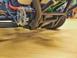
| − | [[File:Cmpe243 F15 Undergrads Final.jpg| | + | [[File:Cmpe243 F15 Undergrads Final.jpg|500px|left|thumb|Undergrads++ Car]] [[File:Cmpe243 F15 Undergrads side.jpg|500px|center|thumb|Under the hood]] |
== Abstract == | == Abstract == | ||
| Line 367: | Line 367: | ||
| − | === CAN | + | === CAN Interface and Power Supply Hardware === |
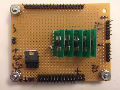
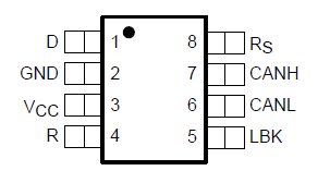
| − | To connect all 5 boards together via CAN bus, five SN65HVD230 CAN transceivers are placed on a prototype board. Furthermore for 5V power supply needed a portable power bank is used and the power is distributed using the same prototype board the CAN transceivers | + | To connect all 5 boards together via CAN bus, five SN65HVD230 CAN transceivers are placed on a prototype board. Furthermore for the 5V power supply needed, a portable power bank is used and the power is distributed using the same prototype board the CAN transceivers uses (figures below). |
| − | [[File:Cmpe243 F15 Undergrads CAN | + | [[File:Cmpe243 F15 Undergrads CAN .png|500px|left|thumb|CAN Interface and Power Supply ]] [[File:Cmpe243 F15 Undergrads CAN HW board.jpg|500px|center|thumb|CAN Interface and Power Supply prototype]] |
=== DBC File Implementation === | === DBC File Implementation === | ||
| Line 495: | Line 495: | ||
Wrapper functions were created in order to simplify the initialization, sending and receiving of messages through the Full CAN api. | Wrapper functions were created in order to simplify the initialization, sending and receiving of messages through the Full CAN api. | ||
| + | |||
| + | <syntaxhighlight lang="cpp”> | ||
bool iCAN_init_FULLCAN(uint32_t * std_list_arr, size_t arraySize); // std_list_arr is an array of accepted message IDs. | bool iCAN_init_FULLCAN(uint32_t * std_list_arr, size_t arraySize); // std_list_arr is an array of accepted message IDs. | ||
bool iCAN_rx(can_fullcan_msg_t *msg, msg_hdr_t *msg_hdr); | bool iCAN_rx(can_fullcan_msg_t *msg, msg_hdr_t *msg_hdr); | ||
bool iCAN_tx(can_msg_t *msg, msg_hdr_t *msg_hdr); | bool iCAN_tx(can_msg_t *msg, msg_hdr_t *msg_hdr); | ||
| + | |||
| + | </syntaxhighlight> | ||
| + | <BR/> | ||
== Master Controller == | == Master Controller == | ||
| Line 584: | Line 589: | ||
For the software part, we configured the CAN bus using the FULL CAN mode. The main advantage of using the FULL CAN is that the processor does not have to parse the incoming message and messages go inside designated mail boxes. To initialize the CAN bus in FULL CAN mode, we set its baud rate to be 100kbps, the receive and send queue size to be 50 and pass an array of accepted message IDs and its size as parameters to the following function which initializes the CAN BUS. | For the software part, we configured the CAN bus using the FULL CAN mode. The main advantage of using the FULL CAN is that the processor does not have to parse the incoming message and messages go inside designated mail boxes. To initialize the CAN bus in FULL CAN mode, we set its baud rate to be 100kbps, the receive and send queue size to be 50 and pass an array of accepted message IDs and its size as parameters to the following function which initializes the CAN BUS. | ||
| − | + | <syntaxhighlight lang="cpp”> | |
| + | bool iCAN_init_FULLCAN(uint32_t * std_list_arr, size_t arraySize); | ||
| + | </syntaxhighlight> | ||
| + | <BR/> | ||
The function returns true if the bus is initialized successfully and all the message IDs are added to the acceptance filter. | The function returns true if the bus is initialized successfully and all the message IDs are added to the acceptance filter. | ||
These messages can then be read using a pointer to the message mailbox as the first parameter and the dbc decode function as the second parameter to the following function: | These messages can then be read using a pointer to the message mailbox as the first parameter and the dbc decode function as the second parameter to the following function: | ||
| + | <syntaxhighlight lang="cpp”> | ||
| + | iCAN_rx(can_fullcan_msg_t *msg, msg_hdr_t *msg_hdr); | ||
| − | + | </syntaxhighlight> | |
| + | <BR/> | ||
For sending, after the DBC file encodes the message, we can transmit it over the CAN bus using the transmit function. First parameter is a pointer to the can_msg_t message and the second is the pointer to the message header generated by dbc parser. | For sending, after the DBC file encodes the message, we can transmit it over the CAN bus using the transmit function. First parameter is a pointer to the can_msg_t message and the second is the pointer to the message header generated by dbc parser. | ||
| − | + | <syntaxhighlight lang="cpp”> | |
| − | + | bool iCAN_tx(can_msg_t *msg, msg_hdr_t *msg_hdr); | |
| + | </syntaxhighlight> | ||
| + | <BR/> | ||
=== Software Design === | === Software Design === | ||
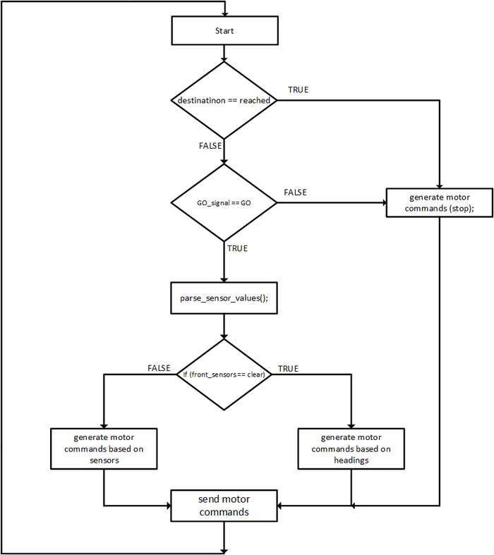
[[File:Cmpe243_F15_Undergrads_System--motor_control_logic.png|700px|centre|thumb|Motor Control Logic]] | [[File:Cmpe243_F15_Undergrads_System--motor_control_logic.png|700px|centre|thumb|Motor Control Logic]] | ||
| − | + | ||
The software design is based on layered architecture. There are a total of three layers and they are listed below: | The software design is based on layered architecture. There are a total of three layers and they are listed below: | ||
| Line 622: | Line 635: | ||
The idea is to run everything in one pass (within the 100Hz task) for logic simplicity. The image above shows the high level view of our driving logic based on the sensor and heading values. | The idea is to run everything in one pass (within the 100Hz task) for logic simplicity. The image above shows the high level view of our driving logic based on the sensor and heading values. | ||
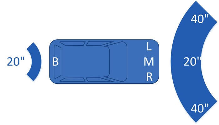
The Image below shows the minimum block values of the sensors. When one of the sensors reads a value lower than its minimum block value, appropriate action is taken. | The Image below shows the minimum block values of the sensors. When one of the sensors reads a value lower than its minimum block value, appropriate action is taken. | ||
| + | |||
[[File:Cmpe243_F15_Undergrads_System--sensor_block_values.jpg|700px|centre|thumb|Sensor minimum block values]] | [[File:Cmpe243_F15_Undergrads_System--sensor_block_values.jpg|700px|centre|thumb|Sensor minimum block values]] | ||
| + | |||
The GPS controller keeps on sending the next checkpoint to the master each time it reaches the current one. After the master receives and reaches the final checkpoint, the GPS controller sets a flag ''final_destination_reached'' and the master responds by resetting the GO signal and commanding the motors to stop. | The GPS controller keeps on sending the next checkpoint to the master each time it reaches the current one. After the master receives and reaches the final checkpoint, the GPS controller sets a flag ''final_destination_reached'' and the master responds by resetting the GO signal and commanding the motors to stop. | ||
| + | |||
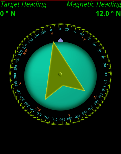
| + | The master controller also makes the decision to turn the car left or right or go straight to reach the destination. This decision is made based on two values: | ||
| + | |||
| + | *Current bearing | ||
| + | *Destination bearing | ||
| + | |||
| + | The algorithm was developed keeping two things in focus: | ||
| + | |||
| + | 1) The car should follow a straight line as long as its current bearing is in X degrees(depending on the precision) of the destination bearing. | ||
| + | |||
| + | 2) If the destination heading differs from the current heading from more than X degrees, turn left or right, depending upon which would be a shorter turn to maintain the destination heading. | ||
| + | |||
| + | [[File:Cmpe243_F15_Undergrads_System--Compass.png|500px|centre|thumb|Current vs Destination bearing]] | ||
| + | We used a tolerance level of 20 degrees (the X value). This ensured that the car is not turning left or right all the time and stays steady without ever being too out of sync from the destination heading. As long as the car is within 20 degrees of the destination heading, it maintains its course. This is still very accurate because as the car gets closer to destination, the destination heading changes drastically allowing the car to zero in on the actual destination. | ||
== Motor I/O Controller == | == Motor I/O Controller == | ||
| Line 658: | Line 687: | ||
|Write and test drivers for the LCD | |Write and test drivers for the LCD | ||
|Complete | |Complete | ||
| − | | | + | |11/02/15 |
|- | |- | ||
|- | |- | ||
| Line 666: | Line 695: | ||
|Interface motor to the rest of the software and get moving under power | |Interface motor to the rest of the software and get moving under power | ||
|Complete | |Complete | ||
| − | |11//15 | + | |11/05/15 |
|- | |- | ||
|- | |- | ||
| Line 677: | Line 706: | ||
|- | |- | ||
|- | |- | ||
| − | |||
| − | |||
| − | |||
| − | |||
| − | |||
| − | |||
|} | |} | ||
| Line 701: | Line 724: | ||
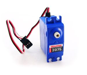
[[File:CmpE243_F15_Servo.jpg|thumb|left|Traxxas Servo]] | [[File:CmpE243_F15_Servo.jpg|thumb|left|Traxxas Servo]] | ||
| + | '''''Servo''''' : | ||
| + | The kit came with a servo motor for turning left and right. The gear ratio for this servo allowed for high torque output with 180 degree end stops. For the purposes of this project we only required the servo to turn approximately 90 degrees for full mobility of the steering. | ||
| + | |||
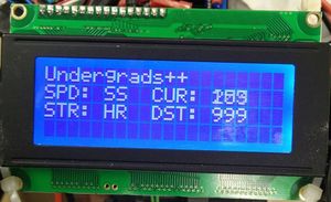
| + | [[File:CmpE243_F15_LCD.jpg|thumb|right|LCD Mounted on Car]] | ||
| + | '''''LCD''''' : | ||
| + | The LCD used for the Undergrads++ car was provided by Preet. This particular LCD did not have any manufacturer name on it and because of this it was a bit difficult to find any documentation for it. We were able to figure out that the screen was 4 row by 20 columns which served well for our purposes. A driver module was also provided with the LCD which enabled communication over UART. Luckily, we were able to find commands for the LCD from the wikipedia report page of a previous team who used a similar LCD. To display data to the LCD we sent these commands over UART along with slight delays so that the LCD would have ample time to respond. We had the following information displayed on the screen: steering, speed, current heading and destination heading as well as front, left, right and rear distance sensor values. | ||
| + | |||
| + | |||
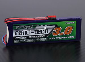
| + | [[File:CmpE243_F15_Battery.jpg|thumb|left|Lithium Iron Phosphate Battery (LiFePO4)]] | ||
| + | '''''Battery''''': | ||
| + | After it was learned that the supplied battery with the car kit would not suffice, we decided to get a new battery to reduce the voltage input to the motor in hopes that it would help in slowing it down. After much research, we ordered the Turnigy nano-tech 3000mAh 6.6V LiFePO4 battery. The characteristics of this lithium iron phosphate battery make it very ideal for this project. LiFePO batteries are very resilient to quick discharges and hold up very well to shock or puncturing as compared to the common lithium polymer batteries. | ||
| + | |||
| + | === Hardware Interface === | ||
| + | |||
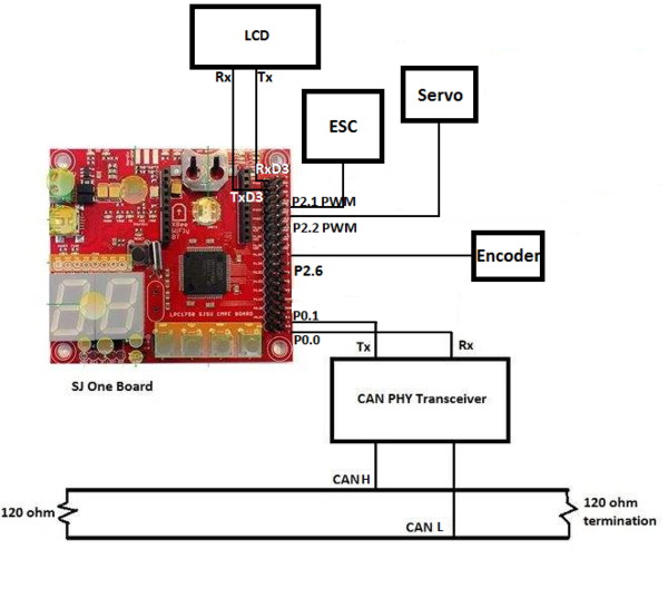
| + | For the overall communication of the car, CAN bus was used for interfacing. However, interfacing to the motor electronic speed controller (ESC), and servo were controlled with the use of Pulse Width Modulation signals (PWM). The ESC uses values ranging from 1ms to 2ms, with 1.5ms being "neutral". The LCD need to receive commands via Universal Asynchronous Receiver/Transmitter (UART) bus. Lastly, the motor encoder used a basic GPIO pin from the SJSU one microcontroller to connect to the encoder's output pin. | ||
| + | [[File:Cmpe243_F15_Motor_Mounted_on_Car.jpg|250px|thumb|right|Motor Mounted on Car]] | ||
| + | '''Motor''' | ||
| + | For the motor, it was necessary to create an ESC programming function in which the provided datasheet for the ESC states that the ESC needs to receive the range of values for forward trigger, and reverse trigger and neutral. This equates to the function sending Neutral, then sending incremental values from neutral up to the max duty cycle, of 20% at 100Hz. Then, the same goes for reverse, one starts at sneding it neutral, then decrements all the way down to a 10% duty cycle. After the ESC is programmed properly for the associated PWM cycle, all that's left is making sure there's at least a 10-20ms delay between each motor control command so that the ESC has enough time to register the receiving commands. From here on out, you can simply sending it any range about about 15.4% duty cycle to the max of 20% duty cycle. Same goes for reverse. MAKE SURE ALL GROUNDS ARE CONNECTED (i.e. ground from power source to a common bus as the microcontroller). | ||
| + | |||
| + | '''Servo''' | ||
| + | Just as the motor needs PWM, the servo does as well. Luckily for us, the servo used the same period 1ms, 1.5ms, and 2ms, which allowed for almost 100% code reuse for controlling the servo. The good part about the servo is that there is no need to initialize, just make sure it has a proper power source, and ALL GROUNDS ARE CONNECTED (i.e. ground from power source to a common bus as the microcontroller) or else it won't work. | ||
| + | |||
| + | '''LCD''' | ||
| + | For the LCD, the baud rate was set automatically. There was, however, an initial command to be sent through UART to initialize the LCD. After that, the LCD can be manipulated using the commands, and sending it the data that you want it to display, with well formatting. | ||
| + | Note: Make sure that the board and LCD are powered at the same time; yes that means unplugging it from your laptop USB, and powering the LCD and then plugging your SJOne board back in. | ||
| + | |||
| + | [[File:Cmpe243_F15_Encoder_Mounted_on_Car.jpg|250px|thumb|left|Encoder Mounted on Car]] | ||
| + | '''Encoder''' | ||
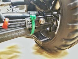
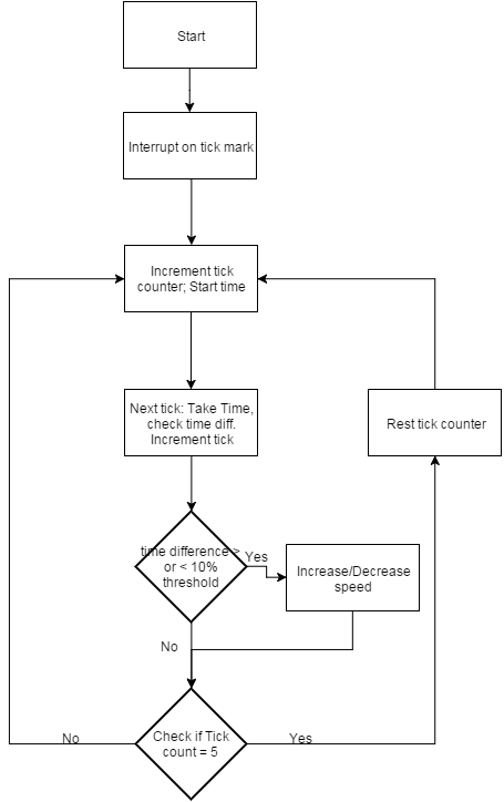
| + | Encoder uses a basic output pin that outputs HIGH for detecting a white line, and a LOW signal for everything else. It was very simple to interface with the microcontroller, as one can simply use a GPIO pin to listen for the HIGH signal, and just set off an interrupt such that there's no delay. For calculating the speed, there first needed to be field testing for a nominal value; this nominal value then becomes the reference point for which you do your calculating. Because the encoder was being triggered five times, we were calculating the time between each tick mark, and seeing if they deviated more than 5-10% from one tick set, to the other. This ensured we get accurate readings of the speed. If the time went outside of the threshold range, the speed of the car would be incremented by a small amount, to try and match the nominal value's speed. | ||
| + | Again, make sure ALL GROUNDS ARE CONNECTED. | ||
| + | |||
| − | |||
| − | |||
| − | |||
| − | |||
| − | |||
| − | |||
| − | |||
| − | |||
=== Software Design === | === Software Design === | ||
| + | For software, the motor and servo controls, were all being called through a real-time scheduler that uses periodic scheduled call back functions: 1Hz, 10Hz, 100Hz, and 1000Hz. The premise, however, is that these functions are strictly timed, and thus, are programmed to crash the board if your code happens to run past it's dedicated time slot. The use of this real-time scheduler has helped us gain a lot of insight into the application, and uses, of a real-time scheduler. | ||
| − | + | ||
| + | '''Motor/Servo Flow''' | ||
| + | [[File:CMPE243_F15_Undergrads++_SoftwareDesign_MotorControlFlow.png|600px|thumb|center|Motor/Servo commands]] | ||
| + | |||
| + | '''LCD Flow''' | ||
| + | [[File:CMPE243_F15_Undergrads++_SoftwareDesign_LCDControlFlow.png|600px|thumb|center|LCD Commands]] | ||
| + | '''LCD Commands''' | ||
| + | The following table shows the commands sent to the LCD over the UART bus. At startup, 0xF0 is sent to the LCD which initializes it to 9600 baud rate. The LCD then waits for any additionally commands to be sent for processing and display. The commands were sent using the 'putline()' and 'putchar()' functions which are built into the UART API. We interfaced the LCD's 'Blight' command for the purposes of alerting if the car's CAN bus is inactive or off. When the bus is off, the LCD LED backlight flashes between 100 and 20 percent. | ||
| + | {| class="wikitable" | ||
| + | |- | ||
| + | ! scope="col"| Command | ||
| + | ! scope="col"| Description | ||
| + | ! scope="col"| Notes | ||
| + | |- | ||
| + | |- | ||
| + | |$GOTO:1:2 | ||
| + | | Moves the cursor to the designated column and row | ||
| + | | Here: the cursor moves to the 1st column and 2nd row | ||
| + | |- | ||
| + | |- | ||
| + | |$CLR_SCR | ||
| + | | Clears the LCD screen | ||
| + | | | ||
| + | |- | ||
| + | |- | ||
| + | |$BLIGHT:75 | ||
| + | | Changes LCD backlight brightness | ||
| + | | Here, the LCD brightness is set to 75 percent of the maximum level | ||
| + | |- | ||
| + | |- | ||
| + | |} | ||
| + | |||
| + | '''Encoder Flow''' | ||
| + | [[File:CMPE243_F15_Undergrads++_SoftwareDesign_EncoderControlFlow.png|600px|thumb|center|Encoder Commands]] | ||
== Sensor Controller == | == Sensor Controller == | ||
| Line 798: | Line 878: | ||
=== Hardware Design === | === Hardware Design === | ||
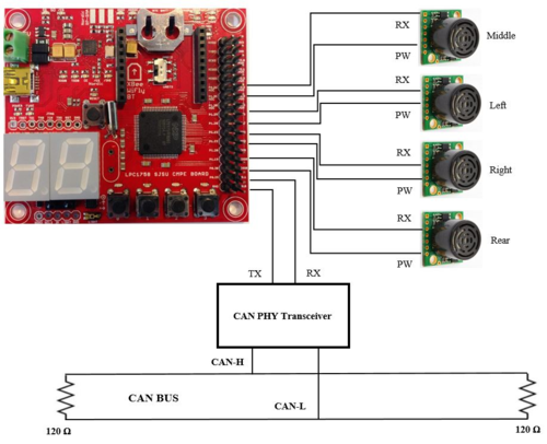
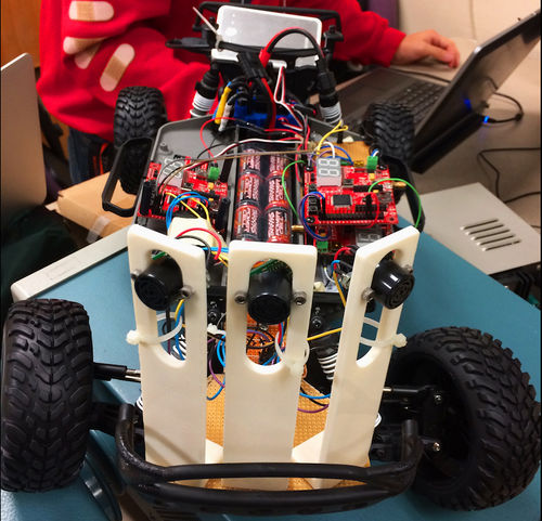
4 LV-MaxSonar sensors are used for the project, they are used for obstacle detection and avoidance. These sensors are able to detect obstacles 0 – 254 inches, though objects 6 inches or closer are simply registered as 6 inches. Sensors are powered with 5Volts (3.3Volts option is also available). Each reading takes 50ms, and each sensor is enabled at a time using the RX pin on it to avoid crosstalk. Three sensors are placed in front of the car (Left , Middle, Right) and one at the back. The image below shows the wired connections between sensors and SJOne board, and the one on the right shows the mounted sensors. | 4 LV-MaxSonar sensors are used for the project, they are used for obstacle detection and avoidance. These sensors are able to detect obstacles 0 – 254 inches, though objects 6 inches or closer are simply registered as 6 inches. Sensors are powered with 5Volts (3.3Volts option is also available). Each reading takes 50ms, and each sensor is enabled at a time using the RX pin on it to avoid crosstalk. Three sensors are placed in front of the car (Left , Middle, Right) and one at the back. The image below shows the wired connections between sensors and SJOne board, and the one on the right shows the mounted sensors. | ||
| − | [[File:Cmpe243 F15 Undergrads SJOne-Sensors.png| | + | |
| + | |||
| + | [[File:Cmpe243 F15 Undergrads SJOne-Sensors.png|500px|left|thumb|Sensor Hardware Design]] [[File:Cmpe243 F15 Undergrads Sensor mount.jpg|500px|center|thumb|Mounted Senors]] | ||
=== Software Design === | === Software Design === | ||
| Line 850: | Line 932: | ||
<syntaxhighlight lang="cpp"> | <syntaxhighlight lang="cpp"> | ||
| − | + | eint3_enable_port2(2, eint_falling_edge, calc_dist_middle); //Middle Sonar | |
</syntaxhighlight><BR/> | </syntaxhighlight><BR/> | ||
Figure C. Enabling the interrupt for GPIO pin2.2 | Figure C. Enabling the interrupt for GPIO pin2.2 | ||
| Line 913: | Line 995: | ||
|Relay CAN Bus messages/tasks. | |Relay CAN Bus messages/tasks. | ||
|Complete | |Complete | ||
| − | |12/10/ | + | |12/10/2015 |
|- | |- | ||
|- | |- | ||
| Line 948: | Line 1,030: | ||
=== Hardware Interface === | === Hardware Interface === | ||
Overall, the interface between Android and the SJOne board is simple. The Bluetooth module (BTBee Pro) is connected to XBEE port on the SJOne board. The UART2 switch is flipped so that the BTBee could accept UART2 line information. The Android writes to the BTBee at 115200 bps. The BTBee then sends the information to the SJOne board through UART2 through a command line. The data is then encoded to fit the CAN bus. Any other CAN transceiver can listen to the message it sends. The RD1 and TD1 pins are connected to the Tx and Rx pins of the CAN Transceiver. The Bridge SJOne board will then properly shift bits into the data field of the CAN bus and transmit it using Full CAN. GPS and Master are continuously listening for messages sent by the Bridge Controller. The checkpoint is the counter that keeps track of the current total coordinates received. At endread, the checkpoint is reset back to 0 so that it can prepare for the next set of coordinates. The flow chart shown below illustrates how the Bridge controller receives coordinates from Android and how it processes in the command terminal. | Overall, the interface between Android and the SJOne board is simple. The Bluetooth module (BTBee Pro) is connected to XBEE port on the SJOne board. The UART2 switch is flipped so that the BTBee could accept UART2 line information. The Android writes to the BTBee at 115200 bps. The BTBee then sends the information to the SJOne board through UART2 through a command line. The data is then encoded to fit the CAN bus. Any other CAN transceiver can listen to the message it sends. The RD1 and TD1 pins are connected to the Tx and Rx pins of the CAN Transceiver. The Bridge SJOne board will then properly shift bits into the data field of the CAN bus and transmit it using Full CAN. GPS and Master are continuously listening for messages sent by the Bridge Controller. The checkpoint is the counter that keeps track of the current total coordinates received. At endread, the checkpoint is reset back to 0 so that it can prepare for the next set of coordinates. The flow chart shown below illustrates how the Bridge controller receives coordinates from Android and how it processes in the command terminal. | ||
| + | |||
| + | |||
[[File:Cmpe243 F15 Undergrads Android Send logic.png|600px|centre|thumb|Android Software Design]] | [[File:Cmpe243 F15 Undergrads Android Send logic.png|600px|centre|thumb|Android Software Design]] | ||
| Line 987: | Line 1,071: | ||
On the SJOne board side, all the operations on the CAN bus happen on the 100Hz Periodic Callback. The flags dictate the flow of transmission of checkpoints. Only when the flags are true will transmission happen. The GO and STOP commands are also set by flags. | On the SJOne board side, all the operations on the CAN bus happen on the 100Hz Periodic Callback. The flags dictate the flow of transmission of checkpoints. Only when the flags are true will transmission happen. The GO and STOP commands are also set by flags. | ||
| − | Video of the application. [ | + | Video of the application. [https://www.youtube.com/watch?v=4FHeaX5tdhA Android Application in Action] |
== Geographical Controller == | == Geographical Controller == | ||
| Line 1,207: | Line 1,291: | ||
==== Algorithms Used ==== | ==== Algorithms Used ==== | ||
=====Finding the correct heading between two geographical coordinates.===== | =====Finding the correct heading between two geographical coordinates.===== | ||
| + | |||
| + | <syntaxhighlight lang="cpp”> | ||
correctHeading = atan2(dy, dx) * 180 / pi; (where dy and dx are the delta of latitude and longitude) | correctHeading = atan2(dy, dx) * 180 / pi; (where dy and dx are the delta of latitude and longitude) | ||
| + | </syntaxhighlight> | ||
| + | <BR/> | ||
=====Finding the distance between two geographical coordinates.===== | =====Finding the distance between two geographical coordinates.===== | ||
| + | <syntaxhighlight lang="cpp”> | ||
dist = sin(degreeToRadian(lat1)) * sin(degreeToRadian(lat2)) + cos(degreeToRadian(lat1)) * cos(degreeToRadian(lat2)) * cos(degreeToRadian(theta)); | dist = sin(degreeToRadian(lat1)) * sin(degreeToRadian(lat2)) + cos(degreeToRadian(lat1)) * cos(degreeToRadian(lat2)) * cos(degreeToRadian(theta)); | ||
dist = acos(dist); | dist = acos(dist); | ||
dist = radianToDegree(dist); | dist = radianToDegree(dist); | ||
dist = dist * 60 * 1.1515 * 1.609344; | dist = dist * 60 * 1.1515 * 1.609344; | ||
| + | </syntaxhighlight> | ||
| + | <BR/> | ||
== Testing & Technical Challenges == | == Testing & Technical Challenges == | ||
| − | |||
| − | |||
| − | |||
=== Problems Encountered === | === Problems Encountered === | ||
| Line 1,300: | Line 1,388: | ||
== Conclusion == | == Conclusion == | ||
| − | + | Self driving cars are the next step that humans as a civilization are taking in the advancement of science and technology and this project is a tiny effort in that area. The project ran almost the entire length of the semester and we as a team learnt a lot from it. Although the main focus of the class lectures were about CAN Bus, basic communication protocols, FreeRTOS and programming paradigms, we had to do much more learning outside of the classroom. We came across really complex hardware and software problems like noise, signal integrity and signal conditioning cannot be solved by software or hardware alone. It takes a combination of the two to solve it. This project also developed our skills to work in teams and collaborate together over a long period of time. Communication is key to finishing a project of this scale. In order for this project to work, every sub-team must come together to integrate separate modules and making them work. | |
=== Project Video === | === Project Video === | ||
| − | + | ||
| + | [https://youtu.be/4FHeaX5tdhA Android Application in Action] | ||
| + | |||
| + | [https://youtu.be/SAUjKmejZGs CMPE 243 Car Test Run] | ||
| + | |||
| + | [https://youtu.be/oaCFjx2T-3Y CMPE 243 Car Test Run Second Angle] | ||
=== Project Source Code === | === Project Source Code === | ||
| Line 1,312: | Line 1,405: | ||
== References == | == References == | ||
=== Acknowledgement === | === Acknowledgement === | ||
| − | + | The team would like to thank Preet for giving us the foundation for the team work on as well as showing us programming techniques and communication protocols. We would like to thank Mr. Leepeng, our team advisor and the other Autocar teams for trading knowledge and having discussions on what to do better. | |
=== References Used === | === References Used === | ||
| + | http://www.freertos.org | ||
[http://developer.android.com/guide/index.html/ Official Android API Guide] | [http://developer.android.com/guide/index.html/ Official Android API Guide] | ||
| − | + | http://www.nxp.com/documents/user_manual/UM10360.pdf | |
| − | + | ||
| + | http://www.socialledge.com/sjsu/index.php?title=SJ_One_Board | ||
Latest revision as of 20:39, 19 December 2015
Contents
Undergrads++
Abstract
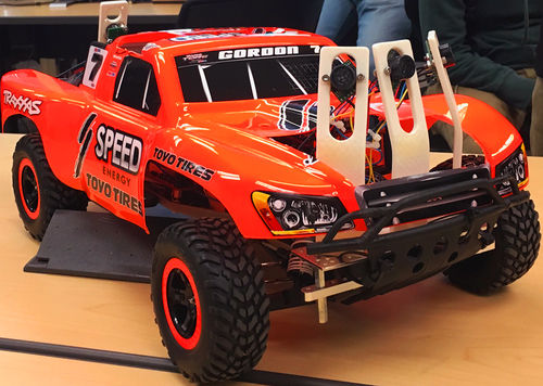
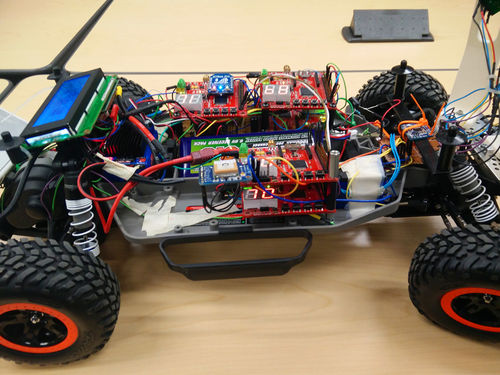
The project is an autonomous car that shall avoid obstacles. The car will consist of five SJ One controllers connected and communicating via one operational CAN bus. Each controller shall be handled by teams of two people per component and integrated to 1 working autonomous car. The Master Controller team shall be responsible for collecting data from the other controllers and guiding the car using high-level logic. The Motor I/O Controller team shall be responsible for the operation of the motors and operation of the LCD display, which will display debugging or current status messages. The Sensor Controller team shall be responsible for collecting data from the sonar sensors and sending the appropriate data. The Geographical Controller team shall be responsible for calculating the orientation of the car as well as the current position in relation to it's desired destination. The Bluetooth/Bridge Controller team shall be responsible for the interface to the end user and sending the way-points. All of these five devices shall operate simultaneously and reach the requested destination.
Objectives & Introduction
- The user shall be able to set a longitude/latitude using an Android app
- The user shall be able to send a Start command to start the navigation routine
- The car shall avoid obstacles and navigate appropriately around them
- The car shall contain sensors in the front and back to go forward and backward without intervention
- The car shall reach the destination before the battery dies
- The car shall contain a GPS and compass to calculate the heading, longitude, and latitude
- The car shall contain a Bluetooth device to receive information from the Android App
- The car shall contain appropriate sensors to internally calculate the speed of the car
- The car shall be able to adjust it's speed appropriately when commanded by the Master controller
- The car shall display appropriate information on the LCD display
Team Members & Responsibilities
Master Controller
- Marvin Flores
- Hassan Naveed
Sensor Controller & Finances
- Arlen Eskandari
- Onyema Ude
GPS Controller & iCAN API
- Calvin Lai
- Jonathon Hongpananon
Motor/LCD Controller
- Hector Prado-Guerrero
- Jashan Singh
Bridge/Android Controller
- Phil Tran
- Shangming Wang
Parts List & Cost
This section goes over the parts that we ordered and the cost of each item.
| Item# | Part Desciption | Vendor | Part Number | Qty | Cost |
|---|---|---|---|---|---|
| 1 | RC Car | Traxxas | Traxxas Slash 2WD VXL 58076 Brushless | 1 | $339.94 |
| 2 | GPS Module | Adafruit Ultimate GPS | Adafruit | 1 | $39.99 |
| 3 | CAN Transceiver breakout board | Anchor | Anchor | 4 | $3.89 |
| 4 | Assembly Components | Amazon, ebay, Halted | (High Quality Jumpers, nuts, screws, standoffs) | NA | $50 |
| 5 | Arduino compatible Tracking Sensor (For controlling the speed) | Phantom YoYo! | Amazon | 2 | $10.12 |
| 6 | Sonar sensor | Maxbotix EZ MB1010 | Amazon | 4 | $29.95 |
| 7 | 3000mAh 2S1P 20~40C LiFePo4 Battery | Turnigy | Hobbyking | 1 | $23.82 |
| 8 | Tripleaxis accelerometer+Magnetometer(Compass) Board | Adafruit | LSM303 | 1 | $20.97 |
| 9 | LCD Display | 1 | given by Preet | ||
| 10 | Brushed Motor | Traxxas | 3785 Titan 12 Turn 550 | 1 | $19 |
| 11 | 7Segment Display | 1 | given by Preet |
Design & Implementation
The section goes over our top-level designs of our project.
CAN Message ID Table
| Sl. No | Module | ID | Type/Bits | xxxxx | Source bits SSS | Destination bits DDD | Hex value | Source | Destination |
|---|---|---|---|---|---|---|---|---|---|
| 1 | Android | 001 | CRITICAL_ERROR_BUS_OFF | 0 0 0 0 0 | x x x | 0 0 0 | 0x008 Android
0x010 Master 0x018 Sensor 0x020 GPS 0x028 Motor-LCD |
ANY | ALL |
| 2 | Master | 010 | ANDROID->MASTER | 0 0 0 0 1 | 0 0 1 | 0 1 0 | 0x04A
|
Android | Master |
| 3 | Sensor | 011 | RC_PARAMS | 0 0 0 1 0 | 0 0 1 | 0 1 0 | 0x08A
|
Android | Master |
| 4 | GPS | 100 | SET_DEST | 0 0 0 1 1 | 0 0 1 | 0 1 0 | 0x0CA
|
Android | Master |
| 5 | MOTOR_LCD | 101 | COORDINATES ANDROID->MASTER | 0 0 1 0 0 | 0 0 1 | 0 1 0 | 0x10A
|
Android | Master |
| 6 | X | X | SENSOR_MASTER_REG | 0 0 1 0 1 | 0 1 1 | 0 1 0 | 0x14A
|
Sensor | Master |
| 7 | X | X | MASTER_ANDROID_REG | 0 0 1 1 0 | 0 1 0 | 0 0 1 | 0x14A
|
Master | Android |
| 8 | X | X | COORDINATES MASTER->ANDROID | 0 0 1 1 1 | 0 1 0 | 0 0 1 | 0x1D1
|
Master | Android |
| 9 | X | X | MASTER_COMMANDS-> Motor | 0 1 0 0 0 | 0 1 0 | 1 0 1 | 0x215
|
Master | IO_Motor |
| 10 | X | X | MASTER_COMMANDS->SENSOR | 0 1 0 0 1 | 0 1 0 | 0 1 1 | 0x253
|
Master | Sensor |
| 11 | X | X | MASTER_COMMANDS_READ-> IO | 0 1 0 1 0 | 0 1 0 | 1 0 1 | 0x295
|
Master | IO_Motor |
| 12 | X | X | IO_MOTOR_MASTER_REG | 0 1 0 1 1 | 1 0 1 | 0 1 0 | 0x2D5
|
IO_Motor | Master |
| 13 | X | X | MASTER_COMMANDS->GPS | 0 1 1 0 0 | 0 1 0 | 1 0 0 | 0x314
|
Master | GPS |
| 14 | X | X | GPS_MASTER_REG | 0 1 1 0 1 | 1 0 0 | 0 1 0 | 0x362
|
GPS | Master |
| 15 | X | X | MASTER_COMMANDS_WRITE-> IO | 0 1 1 1 0 | 0 1 0 | 1 0 1 | 0x395
|
Master | IO_Motor |
CAN Interface and Power Supply Hardware
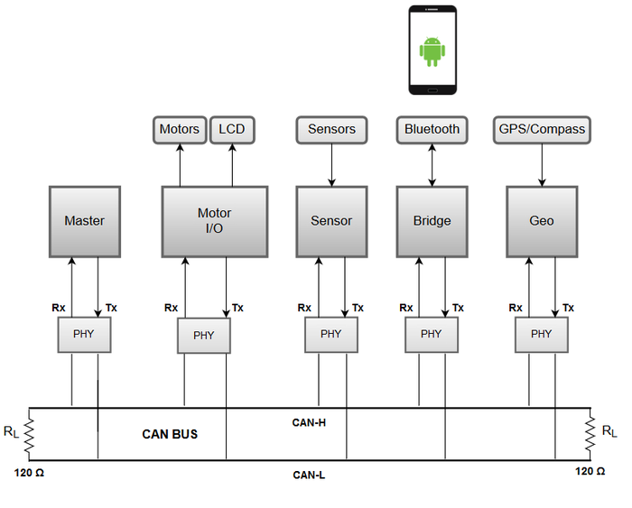
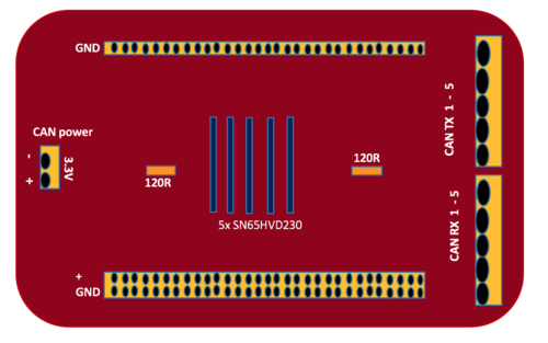
To connect all 5 boards together via CAN bus, five SN65HVD230 CAN transceivers are placed on a prototype board. Furthermore for the 5V power supply needed, a portable power bank is used and the power is distributed using the same prototype board the CAN transceivers uses (figures below).
DBC File Implementation
Throughout the development and life-cycle of our project we used a DBC file and a python parser to generate C-code for the five controllers. The DBC file contained CAN messages organized in a particular format, which the python parser generated appropriate code for each CAN node. The C-code generated contained inline functions to convert messages to and from raw CAN messages using marshal and unmarshal operations. This provided a centralized CAN message base for all of the teams to use so that there was consistency throughout the project.
- The DBC file :
 VERSION ""


 NS_ :
 	NS_DESC_
 	CM_
 	BA_DEF_
 	BA_
 	VAL_
 	CAT_DEF_
 	CAT_
 	FILTER
 	BA_DEF_DEF_
 	EV_DATA_
 	ENVVAR_DATA_
 	SGTYPE_
 	SGTYPE_VAL_
 	BA_DEF_SGTYPE_
 	BA_SGTYPE_
 	SIG_TYPE_REF_
 	VAL_TABLE_
 	SIG_GROUP_
 	SIG_VALTYPE_
 	SIGTYPE_VALTYPE_
 	BO_TX_BU_
 	BA_DEF_REL_
 	BA_REL_
 	BA_DEF_DEF_REL_
 	BU_SG_REL_
 	BU_EV_REL_
 	BU_BO_REL_
 	SG_MUL_VAL_

 BS_:

 BU_: NOONE SENSOR MASTER MOTOR GPS ANDROID

 BO_ 100 HEARTBEAT: 1 MASTER
  SG_ MASTER_HEARTBEAT_cmd : 0|8@1+ (1,0) [0|0] "" SENSOR,MOTOR

 BO_ 600 INFO_SONARS: 4 SENSOR
  SG_ SENSOR_INFO_SONARS_left : 0|8@1+ (1,0) [0|255] "inch" MASTER
  SG_ SENSOR_INFO_SONARS_middle : 8|8@1+ (1,0) [0|255] "inch" MASTER
  SG_ SENSOR_INFO_SONARS_right : 16|8@1+ (1,0) [0|255] "inch" MASTER
  SG_ SENSOR_INFO_SONARS_rear : 24|8@1+ (1,0) [0|255] "inch" MASTER

 BO_ 604 MOTOR_CMD: 2 MASTER
  SG_ MASTER_MOTOR_CMD_steer : 0|8@1+ (1,0) [0|20] "" MOTOR
  SG_ MASTER_MOTOR_CMD_drive : 8|8@1+ (1,0) [0|20] "" MOTOR

 BO_ 700 STOP_GO_CMD: 1 ANDROID
  SG_ ANDROID_STOP_CMD_signal : 0|8@1+ (1,0) [0|0] "" MASTER,GPS

 BO_ 708 INFO_CHECKPOINTS: 1 ANDROID
  SG_ ANDROID_INFO_CHECKPOINTS_count : 0|8@1+ (1,0) [0|255] "" MASTER,GPS

 BO_ 712 INFO_COORDINATES: 8 ANDROID
  SG_ GPS_INFO_COORDINATES_lat : 0|32@1+ (0.00001,0) [0|0] "" MASTER,GPS
  SG_ GPS_INFO_COORDINATES_long : 32|32@1+ (0.00001,0) [0|0] "" MASTER,GPS

 BO_ 716 INFO_HEADING: 4 GPS
  SG_ GPS_INFO_HEADING_current : 0|16@1- (1,0) [0|0] "" MASTER
  SG_ GPS_INFO_HEADING_dst : 16|16@1- (1,0) [0|0] "" MASTER

 BO_ 720 DESTINATION_REACHED: 1 GPS
  SG_ GPS_DESTINATION_REACHED_signal : 0|8@1+ (1,0) [0|0] "" MASTER,ANDROID

 CM_ BU_ NOONE "No node, used to indicate if it's a debug message going to no one";
 CM_ BU_ MASTER "The driver controller driving the car";
CM_ BU_ SENSOR "The sensor controller of the car";
 CM_ BU_ MOTOR "The motor controller of the car";
 CM_ BU_ ANDROID "The android controller of the car";
 CM_ BO_ 100 "Sync message used to synchronize the controllers";

 BA_DEF_  "BusType" STRING ;
 BA_DEF_ SG_ "FieldType" STRING ;
 BA_DEF_ BO_ "GenMsgCycleTime" INT 0 0;

 BA_DEF_DEF_ "BusType" "CAN";
 BA_DEF_DEF_ "FieldType" "";

 BA_ "GenMsgCycleTime" BO_ 100 1000;
 BA_ "GenMsgCycleTime" BO_ 200 100;
 BA_ "GenMsgCycleTime" BO_ 300 100;
 BA_ "FieldType" SG_ 100 MASTER_HEARTBEAT_cmd "MASTER_HEARTBEAT_cmd"
 BA_ "FieldType" SG_ 604 MASTER_MOTOR_CMD_drive "MASTER_MOTOR_CMD_drive"
 BA_ "FieldType" SG_ 604 MASTER_MOTOR_CMD_steer "MASTER_MOTOR_CMD_steer"

 VAL_ 100 MASTER_HEARTBEAT_cmd 0 "MASTER_HEARTBEAT_cmd_NOOP" 1 "MASTER_HEARTBEAT_cmd_SYNC" 2 "MASTER_HEARTBEAT_cmd_REBOOT" ;
 VAL_ 604 MASTER_MOTOR_CMD_drive 4 "MASTER_MOTOR_CMD_drive_FAST" 3 "MASTER_MOTOR_CMD_drive_MEDIUM" 2 "MASTER_MOTOR_CMD_drive_SLOW" 1 "MASTER_MOTOR_CMD_drive_REVERSE" 0 "MASTER_MOTOR_CMD_drive_STOP" ;
 VAL_ 604 MASTER_MOTOR_CMD_steer 4 "MASTER_MOTOR_CMD_steer_HARD_RIGHT" 3 "MASTER_MOTOR_CMD_steer_SOFT_RIGHT" 2 "MASTER_MOTOR_CMD_steer_STRAIGHT" 1 "MASTER_MOTOR_CMD_steer_SOFT_LEFT" 0 "MASTER_MOTOR_CMD_steer_HARD_LEFT"   ;
Git Submodule Add-on
To increase productivity and be more organized through the life-cycle of this project, our team implemented and used a git submodule. A git submodule is a separate Git repository, which is a subdirectory of our entire main Git repository. This allows us to clone another repository within our project and keep commit history of this submodule separate from the separated projects. The Git submodule allowed a central repository to be used for common code such as the DBC file, python parser, and other source/header files we shared. Due to the fact that every team had a separate branch they were working on (for each controller), there was no way to share code throughout each of the different groups. The submodule made code accessible to all teams instead of manually making changes when necessary. For example, if 1 team made a change to a file, then the other 4 teams already have the recent change without having to manually update. The update is automatic to everyone who has the Git submodule set up.
- To set up a git submodule you can perform the following instructions:
- Create your separate repository on GitLab.com or GitHub.com, whichever Git repository you prefer to use.
- Execute : git submodule add ssh_url relative_path_to_new_dir
- Execute : git status
- Notice a new change to be commited. There should be a .gitmodule created. This contains details supplied about the new submodule.
- Execute : git submodule init
- Execute : git submodule update
- To use the git submodule you just 'cd' into the directory where the git submodule repo is located, and treat it as an independent Git project. There is a master branch you can checkout and pull from to pull-in the most recent changes. Make commits and push like you would to any other Git project. When there are changes made to this Git submodule then there will be new changes shown in the top project directory. You will want to add this change to your next commit so that your top project points to the correct Git submodule commit number.
Full CAN Implementation
Our project uses the Full CAN available on the LPC1758. This method of interfacing with the CAN bus allows the microcontroller to use hardware based CAN message filtering as opposed to software based filtering. Message IDs are added to the acceptance list during the CAN initialization stage where they will each be allocated a space in memory used to store a pointer to messages. During runtime accepted messages will be placed directly into RAM and the reference pointer to this message will be stored in the previously allocated space. Since messages are automatically placed in RAM, there is no longer a need to poll the CAN bus or set a timeout for waiting on messages to arrive. We can now check for new messages whenever we feel that fresh information is required.
The use of the Full CAN is similar to that of the regular CAN save for two points.
- During initialization accepted message ids must be added to the acceptance filter using the CAN_fullcan_add_entry() function found in the provided CAN api.
- Messages are retrieved using the CAN_fullcan_get_entry_ptr() function found in the provided CAN api. This function will return a pointer to a can_fullcan_msg_t found in memory.
Wrapper functions were created in order to simplify the initialization, sending and receiving of messages through the Full CAN api.
 bool iCAN_init_FULLCAN(uint32_t * std_list_arr, size_t arraySize); // std_list_arr is an array of accepted message IDs.
 bool iCAN_rx(can_fullcan_msg_t *msg, msg_hdr_t *msg_hdr);
 bool iCAN_tx(can_msg_t *msg, msg_hdr_t *msg_hdr);
Master Controller
Master Controller
- Marvin Flores
- Hassan Naveed
Master Controller Team Schedule
| Sl. No | Start Date | End Date | Task | Status | Actual Completion Date |
|---|---|---|---|---|---|
| 1 | 10/6/2015 | 10/13/2015 | propose CAN message IDs, data length, and priorities. testing communication between the other boards via CAN bus | Complete | 10/19/2015 |
| 2 | 10/13/2015 | 10/20/2015 | Process motor and Sensor data. Vehicle should be able to run and stop based on the sensor readings. | Complete | 11/03/2015 |
| 3 | 10/20/2015 | 10/27/2015 | Process heading data and sends appropriate message to the motor/LCD team. | Complete | 12/14/2015 |
| 4 | 10/27/2015 | 11/10/2015 | Overall CAN bus system implementation. all boards should be able to communicate properly. Master should be able to send/receive message to/from any module(board.) The master should be able to process the messages accordingly. | Complete | 12/07/2015 |
| 5 | 11/10/2015 | 11/17/2015 | Testing/debugging part 1. Master should be able to receive commands from the Android team and be able execute these commands properly. The master should be able to send commands to the other boards. The vehicle should be running and avoiding obstacles. | Complete | 12/16/2015 |
| 6 | 11/17/2015 | 11/24/2015 | Testing/debugging part 2. Master should be able to request GPS coordinates information from the GPS team and be able to make the car move from origin point to the target point. | N/A (This task was reassigned to the GPS team) | 12/16/2015 |
| 7 | 11/24/2015 | 12/01/2015 | Testing/debugging part 3, Finalizing the project. All messages, commands, and requests are handled accordingly. The vehicle should be avoiding obstacles, and is able to go to the target location. | Complete | 12/16/2015 |
Hardware Design
For the master controller, hardware part essentially covers setting up the CAN bus. The master controller communicates with all other controllers on board i.e the motor, android, GPS, compass and sensors. The bus was set up using five SN65HVD233-HT 3.3-V CAN transceiver chips to send and receive CAN messages from the master controller.
Hardware Interface
The RD1 (pin 0.0) and TD1 (pin 0.1) on the SJ ONE board are connected to the CAN RECEIVE data output and CAN TRANSMIT data input pins on the CAN transceiver. A 120 ohm resistor is attached as a termination resistor between CANH and CANL pins of the two transceivers. This ensures that a transmitting node does not get its own reflection. For the software part, we configured the CAN bus using the FULL CAN mode. The main advantage of using the FULL CAN is that the processor does not have to parse the incoming message and messages go inside designated mail boxes. To initialize the CAN bus in FULL CAN mode, we set its baud rate to be 100kbps, the receive and send queue size to be 50 and pass an array of accepted message IDs and its size as parameters to the following function which initializes the CAN BUS.
bool iCAN_init_FULLCAN(uint32_t * std_list_arr, size_t arraySize);
The function returns true if the bus is initialized successfully and all the message IDs are added to the acceptance filter.
These messages can then be read using a pointer to the message mailbox as the first parameter and the dbc decode function as the second parameter to the following function:
iCAN_rx(can_fullcan_msg_t *msg, msg_hdr_t *msg_hdr);
For sending, after the DBC file encodes the message, we can transmit it over the CAN bus using the transmit function. First parameter is a pointer to the can_msg_t message and the second is the pointer to the message header generated by dbc parser.
bool iCAN_tx(can_msg_t *msg, msg_hdr_t *msg_hdr);
Software Design
The software design is based on layered architecture. There are a total of three layers and they are listed below:
- Communication layer - responsible for receiving CAN messages
- Data layer - responsible for extracting or encoding the data from CAN messages
- Control layer - responsible for making decisions based on data processing and controlling the overall behavior of the car.
All layers are being done in the 100Hz task. First, the Communication layer handles all the incoming messages sent to the MASTER CONTROLLER (i.e. Heading values, STOP/GO Signal, Sensor values, and Destination reached signal). All values are saved in their respective global variables.
Next, The data layer parses the values in the following order:
1.) Check whether we have a STOP/GO signal or Destination reached signal.
2.) Parse the sensor values; comparing them to their minimum block values.
3.) Generate motor commands based on the parsed sensor values if the car is about to hit an object.
4.) Parse the destination and current heading sent by the GPS controller and set car steering direction accordingly.
5.) Send motor commands.
The idea is to run everything in one pass (within the 100Hz task) for logic simplicity. The image above shows the high level view of our driving logic based on the sensor and heading values. The Image below shows the minimum block values of the sensors. When one of the sensors reads a value lower than its minimum block value, appropriate action is taken.
The GPS controller keeps on sending the next checkpoint to the master each time it reaches the current one. After the master receives and reaches the final checkpoint, the GPS controller sets a flag final_destination_reached and the master responds by resetting the GO signal and commanding the motors to stop.
The master controller also makes the decision to turn the car left or right or go straight to reach the destination. This decision is made based on two values:
- Current bearing
- Destination bearing
The algorithm was developed keeping two things in focus:
1) The car should follow a straight line as long as its current bearing is in X degrees(depending on the precision) of the destination bearing.
2) If the destination heading differs from the current heading from more than X degrees, turn left or right, depending upon which would be a shorter turn to maintain the destination heading.
We used a tolerance level of 20 degrees (the X value). This ensured that the car is not turning left or right all the time and stays steady without ever being too out of sync from the destination heading. As long as the car is within 20 degrees of the destination heading, it maintains its course. This is still very accurate because as the car gets closer to destination, the destination heading changes drastically allowing the car to zero in on the actual destination.
Motor I/O Controller
Motor/LCD Controller
- Hector Prado-Guerrero
- Jashan Singh
Motor control/LCD Team Schedule
| Sl. No | Start Date | End Date | Task | Status | Actual Completion Date |
|---|---|---|---|---|---|
| 1 | 10/06/15 | 10/13/15 | Write and test drivers for the brushless motor | Complete | 10/28/15 |
| 2 | 10/13/15 | 10/20/15 | Write and test drivers for the LCD | Complete | 11/02/15 |
| 3 | 10/20/15 | 10/27/15 | Interface motor to the rest of the software and get moving under power | Complete | 11/05/15 |
| 4 | 10/27/15 | 11/03/15 | Interface LCD to accept and display data from CAN messages | Complete | 11/25/15 |
Hardware Design
For the hardware aspect of the Motor/IO group, there were four modules that needed to be designed, and integrated: ESC/DC motor, Servo motor, LCD, and wheel encoder. The ESC/DC motor module is what controls the speed of the car; Servo motor controls the steering of the car; LCD displays important information about the status of the car; wheel encoder dynamically adjusts car speed based off of a reference speed in case the car's battery starts to die, or the car begins going uphill, for example.
Parts and Description
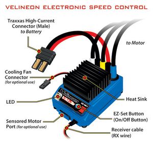
ESC : The kit for the car included the VXL-3s electronic speed controller (ESC) for motor control. Most of the motor/LCD team’s time was spent interfacing the ESC with the software. The ESC required a very intricate initialization of its subprofiles to operate properly. This initialization process involved sending sequential PWM signals to the ESC before signals could be sent to the motor. Once figuring out the proper initialization process, we were able to get control of the motor. The ESC was initialized to a 100 hz PWM communication frequency, and after several testing sessions we found out that a 15.75%, 15% and 13.75% duty cycle was required for forward, neutral and reverse, respectively.
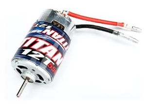
Motor : The car kit also included the Velineon 3500 Brushless Motor. Since this motor was a brushless motor, it required a very specific range of PWM signals to operate. For our purposes, we required low to medium speed range for the motor. However, we soon found out that this motor would not serve us for that purpose because it is almost impossible for it to go slow as it is made to go at higher speed which was unbeknownst to us. To mitigate this, the Traxxas 3785 Titan 12 Turn 550 brushed motor was used. Since this motor was brushed, we were able to get the car moving at medium to very low speeds which enabled us to make proper turning maneuvers.
Servo : The kit came with a servo motor for turning left and right. The gear ratio for this servo allowed for high torque output with 180 degree end stops. For the purposes of this project we only required the servo to turn approximately 90 degrees for full mobility of the steering.
LCD : The LCD used for the Undergrads++ car was provided by Preet. This particular LCD did not have any manufacturer name on it and because of this it was a bit difficult to find any documentation for it. We were able to figure out that the screen was 4 row by 20 columns which served well for our purposes. A driver module was also provided with the LCD which enabled communication over UART. Luckily, we were able to find commands for the LCD from the wikipedia report page of a previous team who used a similar LCD. To display data to the LCD we sent these commands over UART along with slight delays so that the LCD would have ample time to respond. We had the following information displayed on the screen: steering, speed, current heading and destination heading as well as front, left, right and rear distance sensor values.
Battery: After it was learned that the supplied battery with the car kit would not suffice, we decided to get a new battery to reduce the voltage input to the motor in hopes that it would help in slowing it down. After much research, we ordered the Turnigy nano-tech 3000mAh 6.6V LiFePO4 battery. The characteristics of this lithium iron phosphate battery make it very ideal for this project. LiFePO batteries are very resilient to quick discharges and hold up very well to shock or puncturing as compared to the common lithium polymer batteries.
Hardware Interface
For the overall communication of the car, CAN bus was used for interfacing. However, interfacing to the motor electronic speed controller (ESC), and servo were controlled with the use of Pulse Width Modulation signals (PWM). The ESC uses values ranging from 1ms to 2ms, with 1.5ms being "neutral". The LCD need to receive commands via Universal Asynchronous Receiver/Transmitter (UART) bus. Lastly, the motor encoder used a basic GPIO pin from the SJSU one microcontroller to connect to the encoder's output pin.
Motor For the motor, it was necessary to create an ESC programming function in which the provided datasheet for the ESC states that the ESC needs to receive the range of values for forward trigger, and reverse trigger and neutral. This equates to the function sending Neutral, then sending incremental values from neutral up to the max duty cycle, of 20% at 100Hz. Then, the same goes for reverse, one starts at sneding it neutral, then decrements all the way down to a 10% duty cycle. After the ESC is programmed properly for the associated PWM cycle, all that's left is making sure there's at least a 10-20ms delay between each motor control command so that the ESC has enough time to register the receiving commands. From here on out, you can simply sending it any range about about 15.4% duty cycle to the max of 20% duty cycle. Same goes for reverse. MAKE SURE ALL GROUNDS ARE CONNECTED (i.e. ground from power source to a common bus as the microcontroller).
Servo Just as the motor needs PWM, the servo does as well. Luckily for us, the servo used the same period 1ms, 1.5ms, and 2ms, which allowed for almost 100% code reuse for controlling the servo. The good part about the servo is that there is no need to initialize, just make sure it has a proper power source, and ALL GROUNDS ARE CONNECTED (i.e. ground from power source to a common bus as the microcontroller) or else it won't work.
LCD For the LCD, the baud rate was set automatically. There was, however, an initial command to be sent through UART to initialize the LCD. After that, the LCD can be manipulated using the commands, and sending it the data that you want it to display, with well formatting. Note: Make sure that the board and LCD are powered at the same time; yes that means unplugging it from your laptop USB, and powering the LCD and then plugging your SJOne board back in.
Encoder Encoder uses a basic output pin that outputs HIGH for detecting a white line, and a LOW signal for everything else. It was very simple to interface with the microcontroller, as one can simply use a GPIO pin to listen for the HIGH signal, and just set off an interrupt such that there's no delay. For calculating the speed, there first needed to be field testing for a nominal value; this nominal value then becomes the reference point for which you do your calculating. Because the encoder was being triggered five times, we were calculating the time between each tick mark, and seeing if they deviated more than 5-10% from one tick set, to the other. This ensured we get accurate readings of the speed. If the time went outside of the threshold range, the speed of the car would be incremented by a small amount, to try and match the nominal value's speed. Again, make sure ALL GROUNDS ARE CONNECTED.
Software Design
For software, the motor and servo controls, were all being called through a real-time scheduler that uses periodic scheduled call back functions: 1Hz, 10Hz, 100Hz, and 1000Hz. The premise, however, is that these functions are strictly timed, and thus, are programmed to crash the board if your code happens to run past it's dedicated time slot. The use of this real-time scheduler has helped us gain a lot of insight into the application, and uses, of a real-time scheduler.
Motor/Servo Flow
LCD Flow
LCD Commands The following table shows the commands sent to the LCD over the UART bus. At startup, 0xF0 is sent to the LCD which initializes it to 9600 baud rate. The LCD then waits for any additionally commands to be sent for processing and display. The commands were sent using the 'putline()' and 'putchar()' functions which are built into the UART API. We interfaced the LCD's 'Blight' command for the purposes of alerting if the car's CAN bus is inactive or off. When the bus is off, the LCD LED backlight flashes between 100 and 20 percent.
| Command | Description | Notes |
|---|---|---|
| $GOTO:1:2 | Moves the cursor to the designated column and row | Here: the cursor moves to the 1st column and 2nd row |
| $CLR_SCR | Clears the LCD screen | |
| $BLIGHT:75 | Changes LCD backlight brightness | Here, the LCD brightness is set to 75 percent of the maximum level |
Encoder Flow
Sensor Controller
Sensor Controller & Finances
- Arlen Eskandari
- Onyema Ude
Sensor Controller Team Schedule
| Sl. No | Start Date | End Date | Task | Status | Actual Completion Date |
|---|---|---|---|---|---|
| 1 | 10/7/2015 | 10/14/2015 | Ordering the sensors and studying the sensor's datasheet | Complete | 10/17/2015 |
| 2 | 10/14/2015 | 10/30/2015 | Reading Sensor's data and preparing it to be sent over the CAN bus | Complete | 10/17/2015 |
| 3 | 10/30/2015 | 11/7/2015 | Normalizing sensor data values and sending it to the Master through CAN bus | Complete | 11/09/2015 |
| 4 | 10/24/2015 | 10/30/2015 | Implementation with multiple sensors | Complete | 11/09/2015 |
| 5 | 10/30/2015 | 11/24/2015 | Sending multiple sensor data to the master through CAN bus | Complete | 11/09/2015 |
| 6 | 10/24/2015 | 11/25/2015 | Optimizing the code | Complete | 12/12/2015 |
| 7 | 12/01/2015 | 12/17/2015 | Collaborating with other teams and updating the code as needed | Complete | 12/16/2015 |
Hardware Design
4 LV-MaxSonar sensors are used for the project, they are used for obstacle detection and avoidance. These sensors are able to detect obstacles 0 – 254 inches, though objects 6 inches or closer are simply registered as 6 inches. Sensors are powered with 5Volts (3.3Volts option is also available). Each reading takes 50ms, and each sensor is enabled at a time using the RX pin on it to avoid crosstalk. Three sensors are placed in front of the car (Left , Middle, Right) and one at the back. The image below shows the wired connections between sensors and SJOne board, and the one on the right shows the mounted sensors.
Software Design
In this project the "PWM" option of the sonar sensor is used to measure the distance. 250ms after power up the sensors are ready to take their first measurement, the very first measurement takes 98ms (an additional 49ms for initial calibration) and the consecutive measurements take 49ms each.
The software starts the measurement in order of Left, middle, right, and rear (Figure A). To start the measurement the RX pin of the sensor (which is connected to a dedicated GPIO pin separately for each sensor) is set high for 50ms (49ms is the minimum), at the moment the software saves the system clock uptime in a variable "trig_time" (Figure B). As soon as sensor is enabled, it sends out an ultrasonic burst, then the moment sensors receives the bounced back signal from an obstacle the "PW" pin of the sensor which is connected to an "interrupt enabled" (falling edge) GPIO pin is set low (Figure C). The moment the Interrupt enabled GPIO pin goes low, the interrupt service routine goes to "calculate_dist" function to calculate the distance by first subtracting the current system uptime from "trig_time" which was saved before; then dividing it by 174 (given by datasheet) to measure the distance in inches (figure D).
Immediately measuring the next sensor after the current sensor measurement is done gives inconsistent measurements. Adding some delay (50ms in this case) between each measurement solves this problem.
The Range() function (figure A) is called 4 times in the 1Hz periodic function which gives 4 samples from each sensor every second. Each round of ranging takes about 250ms (50ms for each sensor plus the delays) so the Range() function would outrun even the 10Hz periodic function so it could not be placed there and had to be put in the 1Hz function.
After the left sensor finished its measurement, the RX pin on the left sensor is pulled low to disable the sensor, then the RX pin of the middle sensor is pulled high to enable the sensor (at this moment all other sensors are disabled except the middle one to eliminate crosstalk). Then after enabling the middle sensor all the ranging procedure is identical to the one explained above. For the right, and rear sensors the same procedure is repeated all over.
After all the sensors have been saved in separate variables, the variables are packed and sent to "CAN_send" function to be sent to the Master via CAN bus.
void Range()
{
    Range_left();
    delay_ms(50);
    Range_middle();
    delay_ms(50);
    Range_right();
    delay_ms(50);
    Range_rear();
    delay_ms(50);
    CAN_send();
    test();
}
Figure A. Sensor Ranging order
void Range_left(void)
{
    Left_en.setHigh(); // enable Ranging   (enable left sonar)
    delay_us(21); //hold high  >20uS to enable ranging
    Left_trig_time = sys_get_uptime_us(); //get timer at the moment ranging starts
    Left_en.setLow(); // disable ranging of left sonar
}
Figure B. Enabling Sensor and saving the system uptime
eint3_enable_port2(2, eint_falling_edge, calc_dist_middle); //Middle SonarFigure C. Enabling the interrupt for GPIO pin2.2
   void calc_dist_left(void)
{
   left_dist = ((sys_get_uptime_us() - Left_trig_time)/147) ; //each 147uS is 1 inch (Datasheet)
}
Figure D. Function called by the interrupt to calculate the distance
Bluetooth/Bridge Controller
Bridge/Android Controller
- Phil Tran
- Shangming Wang
Android/Bluetooth Team Schedule
| Sl. No | Start Date | End Date | Task | Status | Actual Completion Date |
|---|---|---|---|---|---|
| 1 | 10/6/2015 | 10/15/2015 | Familiarize ourselves with the Android SDK and Java and Google Maps API | Complete | 10/15/2015 |
| 2 | 10/6/2015 | 10/30/2015 | Have a working menu. | Complete | 10/30/2015 |
| 3 | 10/10/2015 | 10/30/2015 | Have the phone communicating with the SJOne board using Bluetooth Bee (UART). | Complete | 11/10/2015 |
| 4 | 10/16/2015 | 11/10/2015 | Relay CAN Bus messages/tasks. | Complete | 12/10/2015 |
| 5 | 10/18/2015 | 11/15/2015 | Be able to input GPS coordinates and have a working map available. | Complete | 10/30/2015 |
| 6 | 10/25/2015 | 11/20/2015 | Start and stop commands should be up and running. Test with GPS. | Complete | 11/05/2015 |
| 7 | 11/15/2015 | 12/01/2015 | Extensive testing of the application and its bridge | Complete | 12/16/2015 |
Hardware Design
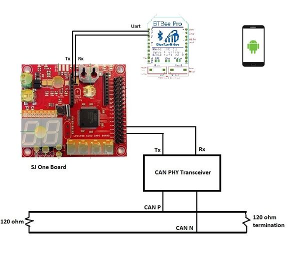
The Bridge communication hardware design is very simple. A BTBEE Pro Bluetooth XBee socket chip is connected to the SJOne board. UART2 port on the SJOne board is used. UART2 Rx and Tx from the pins on the board are connected to the CAN Bus, which is then connected onto the CAN wires.
Hardware Interface
Overall, the interface between Android and the SJOne board is simple. The Bluetooth module (BTBee Pro) is connected to XBEE port on the SJOne board. The UART2 switch is flipped so that the BTBee could accept UART2 line information. The Android writes to the BTBee at 115200 bps. The BTBee then sends the information to the SJOne board through UART2 through a command line. The data is then encoded to fit the CAN bus. Any other CAN transceiver can listen to the message it sends. The RD1 and TD1 pins are connected to the Tx and Rx pins of the CAN Transceiver. The Bridge SJOne board will then properly shift bits into the data field of the CAN bus and transmit it using Full CAN. GPS and Master are continuously listening for messages sent by the Bridge Controller. The checkpoint is the counter that keeps track of the current total coordinates received. At endread, the checkpoint is reset back to 0 so that it can prepare for the next set of coordinates. The flow chart shown below illustrates how the Bridge controller receives coordinates from Android and how it processes in the command terminal.
Software Design
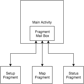
The Android program was written with the Android SDK. The program uses one Activity and three fragments under that Activity (as seen in the Visio diagram). The Activity is the base of the program, and it manages the three fragments in it using a FragmentTransaction and FragmentManager class. There is another layout in the Activity's layout that is specifically made as a fragment container. The Activity features three buttons at the bottom of the screen. Each button with show a fragment. All fragments are constantly running, and the Activity simply hides fragments from the user when the user clicks on a button in the bottom menu. Fragments communicate with each other by using the Activity as a middle man. Information from Fragment A can pass its information to Fragment B by first going through Activity.
Google Maps was inserted into the Maps Fragment. An API key was needed in order for Google Maps to work on the phone. An open source API was used to get the directions and and coordinates of the start and end position. A LatLng list array was inserted to the API to get the list of coordinates. After choosing a point, the "SET" button should be pressed, and the array will be transmitted through bluetooth. The Maps Fragment features buttons that allow operation of the vehicle. These buttons will transmit data to the SJOne board through Bluetooth. All data from Android must first be converted to string and then converted to a byte array in order to be sent over Bluetooth
The Bluetooth API was used to send data from the Android to the SJOne board. When transmitting data from Android to SJOne, a terminal command is used on the SJOne board side to receive data. This is done by using the UART2 ports of the board, and connecting it with a Bluetooth transceiver.
The Bluetooth communication is sent using the write function on Android. Each write function takes a command that the terminal command one the SJOne board will receive. At every command, an action happens. Every command takes a format:
| Command Format | Function |
|---|---|
| bluetooth GO | Send go signal to master. |
| bluetooth STOP | Send stop signal to master. |
| bluetooth RESET | Reset all points. Reset coordinates counter and total size of array. |
| bluetooth read [latitude] [longitude] | Read the points in latitude_longitude format where '_' is a space. |
| bluetooth endread | This is a signal that happens after read is done. Sends flag to periodic scheduler to send coordinates. |
On the SJOne board side, all the operations on the CAN bus happen on the 100Hz Periodic Callback. The flags dictate the flow of transmission of checkpoints. Only when the flags are true will transmission happen. The GO and STOP commands are also set by flags.
Video of the application. Android Application in Action
Geographical Controller
The Geographical Controller is responsible for providing the location of the car and heading direction to the master controller. It receives the way-points from the Bridge Controller and calculates the distance to the final destination. The Master Controller is still responsible for controlling the logic of forward, backward, left, and right to reach the final destination.
GPS Controller
- Calvin Lai
- Jonathon Hongpananon
GPS Controller Team Schedule
| Sl. No | Start Date | End Date | Task | Status | Actual Completion Date |
|---|---|---|---|---|---|
| 1 | 09/29/2015 | 10/06/2015 | Order Adafruit Compass and GPS and solder header pins | Complete | 10/05/2015 |
| 2 | 10/06/2015 | 10/13/2015 | Connect and get minimum UART connection working and interface compass via I2C | Complete | 10/20/2015 |
| 3 | 10/13/2015 | 10/20/2015 | Design GPS task to parse data and get compass heading info | Complete | 10/27/2015 |
| 4 | 10/20/2015 | 10/27/2015 | Integrate GPS, SJSU board, and CAN rx/tx task | Complete | 11/03/2015 |
| 5 | 10/27/2015 | 11/3/2015 | Test Communication with Master Controller and determine final heading using GPS and compass | Complete | 11/10/2015 |
| 6 | 11/03/2015 | 11/10/2015 | Test and debug (if there are any errors/corner cases) | Complete | 11/17/2015 |
| 7 | 11/10/2015 | 11/17/2015 | Optimize the code and testing for stability and report. | Complete | 11/25/2015 |
Hardware Design
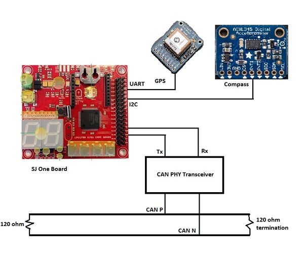
The figure below illustrates the high-level design for the Geographical Controller. The Geographical controller uses an Adafruit GPS Breakout and an Adafruit 10 Degrees Of Freedom (DOF) IMU Breakout. The Adafruit GPS breakout is a GPS module with a 10Hz update rate with a low current draw, which makes this an excellent device for low power consumption. The Adafruit 10-DOF IMU Breakout contains an accelerometer, gyroscope, magnetometer, barometer, and temperature sensor; however, only the magnetometer was used to calculate the heading direction.
Hardware Interface
| Device | Port Source | Port Destination | Device |
|---|---|---|---|
| SJ One | 3v3 | Vin | Adafruit GPS |
| SJ One | GND | GND | Adafruit GPS |
| SJ One | TXD2 | RX | Adafruit GPS |
| SJ One | RXD2 | TX | Adafruit GPS |
| SJ One | 3v3 | Vin | LSM303DLHC (Adafruit Compass) |
| SJ One | GND | GND | LSM303DLHC (Adafruit Compass) |
| SJ One | P0[0] (SDA) | SDA | LSM303DLHC (Adafruit Compass) |
| SJ One | P0[1] (SCL) | SCL | LSM303DLHC (Adafruit Compass) |
Software Design
GPS Data Format
The following table below shows the type of information that is retrieved from the Adafruit GPS chip. When interfaced with the GPS via UART, the string that is received is in the format
$GPGGA,hhmmss.ss,llll.ll,a,yyyyy.yy,a,x,xx,x.x,x.x,M,x.x,M,x.x,xxxx*hh.
The Geographical Controller is responsible for parsing this information and handling the data appropriately.
| Name | Example Data | Description |
|---|---|---|
| Sentence Identifier | $GPGGA | Global Positioning System Fix Data |
| Time | 170834 | 17:08:34 Z |
| Latitude | 4124.8963, N | 41d 24.8963' N or 41d 24' 54" N |
| Longitude | 08151.6838, W | 81d 51.6838' W or 81d 51' 41" W |
| Fix Quality | 1 | Data is from a GPS fix |
| # of Satellites | 05 | 5 Satellites are in view |
| Horizontal Dilution of Precision | 1.5 | Relative accuracy of horizontal position |
| Altitude | 170834 | 280.2 meters above mean sea level |
| Height of geoid above WGS84 ellipsoid | -34.0, M | -34.0 meters |
| Time since last DGPS update | blank | No last update |
| GGPS reference station id | blank | No station id |
| Checksum | *75 | Used by program to check for transmission errors |
After parsing the NMEA string, the correct heading must be calculated to help orient the car in the correct direction. When the correct heading is calculated, the current and correct heading are both sent in a single CAN message to the master controller.
Tasks
| Task Name | Purpose |
|---|---|
| Periodic 10Hz Callback | Calculate and save current heading (10Hz because the GPS is limited to 10Hz refresh rate) |
| Periodic 100Hz Callback | Receive checkpoints from Android Controller and send current heading to Master Controller |
Algorithms Used
Finding the correct heading between two geographical coordinates.
correctHeading = atan2(dy, dx) * 180 / pi; (where dy and dx are the delta of latitude and longitude)
Finding the distance between two geographical coordinates.
   dist = sin(degreeToRadian(lat1)) * sin(degreeToRadian(lat2)) + cos(degreeToRadian(lat1)) * cos(degreeToRadian(lat2)) * cos(degreeToRadian(theta));
   dist = acos(dist);
   dist = radianToDegree(dist);
   dist = dist * 60 * 1.1515 * 1.609344;
Testing & Technical Challenges
Problems Encountered
| # | Module | Issue | Resolution | Impact |
|---|---|---|---|---|
| 1 | Master | data storage/usage (e.g. sensor readings, heading values, etc.) | take the simplest approach, use global variables and label them appropriately; make sure to check whether mutex or access protection is needed. Put everything in 100Hz first before optimizing your code. | Medium |
| 2 | Master | Driving logic | Draw diagrams on paper first. Choose the simplest implementation and avoid unnecessary if statements; test as soon as possible by creating simulations. Create different 'MODES' to test the sensor logic and gps logic independently, before testing both at the same time. | High |
| 3 | Master | Receiving/Sending CAN messages | After testing your logic via simulation, TEST your CAN messages ASAP! structure your messages properly and try to implement DBC parser as soon as possible. | High |
| 4 | Master | Monitor data | Use telemetry instead of printf statements. | Low |
| 5 | Sensor | Reading 4 Sonar Sensors | The SJOne board has only 3 ADCs but the project needed 4 sensor. First Analogue multiplexer was used, but did not work, so eventually PWM mode of the sensor was used via interrupt enabled GPIO. | High |
| 6 | Sensor | Signals Bouncing off of ground | Initially the sensors were mounted on the cars bumper which would make the sonic burst to bounce back from the ground. To solve the problem stands were designed and 3D printed to mount the sensors higher. Furthermore the stands had to be tilted up even more to completely eliminate the ground bouncing effect and only focus on the real obstacles. | High |
| 7 | Android/Bridge Communication | Problems with sending from Fragment to Bluetooth | Transfer any data from Fragment to Activity. Then send data from Activity to Bluetooth. Don't send data straight from Fragment. Utilize Java interfacing. | Medium |
| 8 | Android/Bridge Communication | Bluetooth would not operate properly | First Bluetooth module was broken (BluetoothBee). Second one works for the most part, but data was inconsistent (BluetoothBee). Third worked perfectly, easier to setup than BluetoothBee (BTBee). BTBee is highly recommended. | High |
| 9 | Android/Bridge Communication | Corrupted coordinate values being sent from Android bluetooth | The best way to fix this is to turn all the float values to strings on Android side, convert them to byte arrays, then send. Much easier than converting from float to byte array. | High |
| 10 | Android/Bridge Communication | Improper values sent on CAN Bus | Encoding algorithm was not correct. Bits need to be properly shifted in. Easy fix. Also negative values must be offsetted to positive (Add value to make transmitted value positive) on transmission side, and then offsetted back to negative (Subtract same value to make receive value negative) on receiver side. | Low |
| 11 | Motor | Brushless Motor was too fast | The brushless motor which the car originally came with was too fast and its slowest speed was still too fast for the project. To solve the problem the motor was substituted with a compatible "Brushed" Version of the motor which enabled us to reach much lower speeds. | High |
Conclusion
Self driving cars are the next step that humans as a civilization are taking in the advancement of science and technology and this project is a tiny effort in that area. The project ran almost the entire length of the semester and we as a team learnt a lot from it. Although the main focus of the class lectures were about CAN Bus, basic communication protocols, FreeRTOS and programming paradigms, we had to do much more learning outside of the classroom. We came across really complex hardware and software problems like noise, signal integrity and signal conditioning cannot be solved by software or hardware alone. It takes a combination of the two to solve it. This project also developed our skills to work in teams and collaborate together over a long period of time. Communication is key to finishing a project of this scale. In order for this project to work, every sub-team must come together to integrate separate modules and making them work.
Project Video
CMPE 243 Car Test Run Second Angle
Project Source Code
References
Acknowledgement
The team would like to thank Preet for giving us the foundation for the team work on as well as showing us programming techniques and communication protocols. We would like to thank Mr. Leepeng, our team advisor and the other Autocar teams for trading knowledge and having discussions on what to do better.
References Used
http://www.nxp.com/documents/user_manual/UM10360.pdf
http://www.socialledge.com/sjsu/index.php?title=SJ_One_Board
