Difference between revisions of "F15: Doorknock over Bluetooth"
Proj user20 (talk | contribs) (→Implementation) |
Proj user20 (talk | contribs) (→Project Title) |
||
| (5 intermediate revisions by the same user not shown) | |||
| Line 1: | Line 1: | ||
| − | === | + | == DoorKnock over Bluetooth == |
| − | |||
| − | |||
| − | |||
| − | |||
| − | |||
| − | |||
| − | |||
| − | |||
| − | |||
| − | |||
| − | |||
| − | |||
| Line 21: | Line 9: | ||
== Objectives & Introduction == | == Objectives & Introduction == | ||
| − | |||
| Line 102: | Line 89: | ||
== Design & Implementation == | == Design & Implementation == | ||
| − | + | ||
=== Hardware Design === | === Hardware Design === | ||
| − | + | ||
[[File:cmpe146_F15_Doorknock_HWSchematic.png|thumb|450px|Figure 1. Hardware Design Schematic]] | [[File:cmpe146_F15_Doorknock_HWSchematic.png|thumb|450px|Figure 1. Hardware Design Schematic]] | ||
For the Bluetooth module, UART communication was used to send data to the mobile application, alerting the user of a knock on the door. | For the Bluetooth module, UART communication was used to send data to the mobile application, alerting the user of a knock on the door. | ||
| Line 156: | Line 143: | ||
=== Hardware Interface === | === Hardware Interface === | ||
| − | |||
The communication between the vibration sensor and the SJSU One board takes place through the GPIO pin P0.26, which is configured during initialization to operate as an analog-to-digital converter (ADC). The analog signal is sent over a wire to the board, which then converts the value to a scaled digital value. | The communication between the vibration sensor and the SJSU One board takes place through the GPIO pin P0.26, which is configured during initialization to operate as an analog-to-digital converter (ADC). The analog signal is sent over a wire to the board, which then converts the value to a scaled digital value. | ||
| Line 199: | Line 185: | ||
=== Software Design === | === Software Design === | ||
| − | |||
For this project, the team used FreeRTOS tasks to design and execute the main drivers of the device. The software for the Android application will be discussed in a later section. The flowchart below depicts the basic operation of our device's software. | For this project, the team used FreeRTOS tasks to design and execute the main drivers of the device. The software for the Android application will be discussed in a later section. The flowchart below depicts the basic operation of our device's software. | ||
Latest revision as of 02:17, 19 December 2015
Contents
DoorKnock over Bluetooth
Abstract
This project is to build a door knock sensor that is mounted on a user's door. Using a vibration sensor, the device will alert the user when someone knocks at their door by sending a notification over Bluetooth to the user's mobile android application, that will be developed to pair with the device.
Objectives & Introduction
Project Obejctives
- Be capable of detecting knock on door and notifying user through Android application
- Interface SJSU One board to Piezo vibration sensor through ADC
- Communicate over serial Bluetooth communication using UART bus
- Design and Develop Android application to receive signal from device over Bluetooth
- Implement user notification in Android app
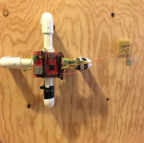
- Design and construct physical housing for device and sensor
Team Members & Responsibilities
- Andrew Herbst
- Sensor interface and UART communication
- Banks Lin
- Android developer and bluetooth communication
Schedule
Show a simple table or figures that show your scheduled as planned before you started working on the project. Then in another table column, write down the actual schedule so that readers can see the planned vs. actual goals. The point of the schedule is for readers to assess how to pace themselves if they are doing a similar project.
| Week# | Date | Task | Status |
|---|---|---|---|
| 1 | 10/23 | Complete Abstract | Completed |
| 2 | 10/30 | Further develop wiki page and purchase/receive components | Completed |
| 3 | 11/6 | Complete bluetooth and Android communication | Completed |
| 4 | 11/13 | Have basic response from the sensor | Completed |
| 5 | 11/20 | Actual communication with bluetooth module | Completed |
| 6 | 11/27 | Debugging on Android side | Completed |
| 7 | 12/4 | Finish last debugging and construct hardware | Completed |
Parts List & Cost
- Piezo Element (vibration sensor): $1.50
- JBtek HC-06 Bluetooth Module: $8
- LPC1758 SJ One Board: $80
- Motorola Nexus 6: $600
- 9V battery: $3
- Various jumper cables: $6
Total Cost: $698.50
Design & Implementation
Hardware Design
For the Bluetooth module, UART communication was used to send data to the mobile application, alerting the user of a knock on the door.
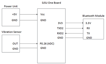
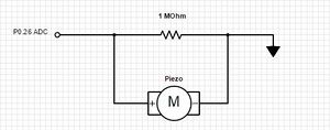
As shown in Figure 1, the ADC input pin (P0.26) of the SJSU One Board was used to collect the analog signal transmitted by the Piezo vibration sensor. Once the analog signal is collected, it would be converted to a digital value using analog-to-digital conversion methods built into the board. This value would then be measured to determine if the vibration was significant enough to be a knock on the door.
The RXD2 and TXD2 pins on the CPU were used for UART communication with the Bluetooth module. Once a knock was detected by the vibration sensor, a single data byte would be transmitted from the controller to the HC-06 which would be able to transmit the data over Bluetooth to the paired mobile device.
In summary, the pin functionality is briefly described below:
- P0.26 was configured to be the ADC input from the vibration sensor.
- TXD2 was used to send data using the UART2 communication bus to the Bluetooth module.
- RXD2 was used to receive data using the UART2 communication bus from the Bluetooth module.
- 3V3 was used to power the HC-06 by a 3.3V output voltage.
Power Unit:
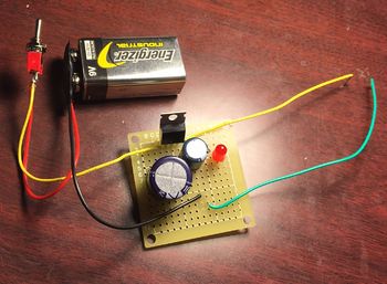
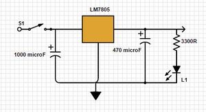
A 9V battery was used to power the device. However, we could not supply a 9V supply to the LPC1758, as it would damage the baord. Thus, a voltage regulator was designed to supply a 5V output to the SJSU One board. Using two capacitors, a switch, and and LED to indicate power on, as shown in Figure 2, the regulator output a steady 5 volts. The design was completed by soldering the components to perf board and the wire leads were attached to the input ports on the SJSU One board to power the device.
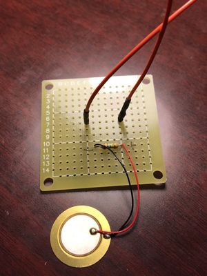
Vibration Sensor: The device was equipped with a Piezo Vibration sensor to detect the knock. The Piezo sensor operates using the piezoelectric effect, which essentially generates a voltage when the disc on the sensor is touched. This generated voltage can be extremely high, which is why a 1 MOhm resistor was used as a voltage divider so that the output would reach the microcontroller at a safe level. When a vibration is detected, an analog signal is sent to the microcontroller through one of the ADC inputs. The resultant value collected by the microcontroller is 0-4096, as the ADC resolution is 12-bits.
Bluetooth Module:
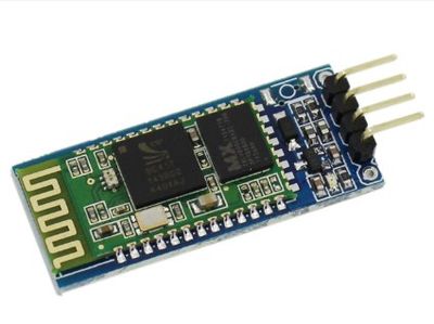
The JBtek HC-06 Bluetooth module was chosen for this device because it is a widely-used and high-quality device, is compatible with the Android Phone, and has low power-consumption. The device acts as a Bluetooth serial interface module to send data over a wireless connection to the paired mobile application. The device has a built-in 2.4GHz transceiver, enabling it to be paired with nearly any Bluetooth device.
Hardware Interface
The communication between the vibration sensor and the SJSU One board takes place through the GPIO pin P0.26, which is configured during initialization to operate as an analog-to-digital converter (ADC). The analog signal is sent over a wire to the board, which then converts the value to a scaled digital value.
//Vibration Sensor interface

LPC_SC->PCONP |= (1 << 12);         // enables power to ADC
LPC_ADC->ADCR |= (1 << 21);         // enables ADC pin
LPC_SC->PCLKSEL0 &= ~(3 << 24);     // clears [25:24]
LPC_SC->PCLKSEL0 |= (1 << 24);      // enables PCLK_ADC / 1
LPC_PINCON->PINSEL1 &= ~(3 << 20);  // clears [21:20]
LPC_PINCON->PINSEL1 |= (1 << 20);   // ADC-3 is on P0.26, select this as ADC0.3
LPC_GPIO0->FIODIR &= ~(1 << 26);    // enables pin as an input
The Bluetooth module acted as a relay between the microcontroller and the user's mobile application. Once a knock was detected, the microcontroller would send a byte of data to the HC-06 using the UART2 bus. One main change made during initialization was to synchronize the baud rate between the board and the Bluetooth module. The HC-06 has a default baud rate of 9600 bps, so the board's baud rate had to be adjusted accordingly. Also, the UART bus was configured to send an 8-bit transfer per data transaction. Each data frame begins with a start bit, indicated by a high-to-low transition, and ends with a stop bit, which is a low-to-high transition. When no activity is occurring on the UART bus, the line is held high. The data frame transaction is illustrated in the figure below.
//Bluetooth module driver

LPC_SC->PCONP |= (1 << 24);         // enables power to UART2
LPC_SC->PCLKSEL1 &= ~(3 << 16);     // clears [17:16]
LPC_SC->PCLKSEL1 |= (1 << 16);      // enables PCLK_UART2 / 1

LPC_PINCON->PINSEL4 &= ~(3 << 16);
LPC_PINCON->PINSEL4 &= ~(3 << 18);
LPC_PINCON->PINSEL4 |= (2 << 16);   // enables Rx/Tx for UART2
LPC_PINCON->PINSEL4 |= (2 << 18);

LPC_UART2->LCR |= (1 << 7);         // DLAB = 1 (table 279)

//calculate baud rate
LPC_UART2->DLM = 0;
uint16_t DLMDLL = 0;
DLMDLL = sys_get_cpu_clock() / (16 * 9600);
LPC_UART2->DLM = (DLMDLL >> 8);     // top 8 bits
LPC_UART2->DLL = (DLMDLL & 0xFF);   // bottom 8 bits
Software Design
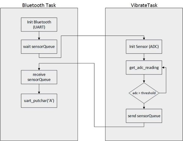
For this project, the team used FreeRTOS tasks to design and execute the main drivers of the device. The software for the Android application will be discussed in a later section. The flowchart below depicts the basic operation of our device's software.
As shown, after initialization of the peripherals, the Bluetooth task waits using a queue for an incoming signal from the vibration sensor task. The vibration sensor polls the ADC input until a voltage is detected above the minimum threshold, indicating a knock on the door. At this point, an item is placed on the queue and the higher priority Bluetooth task receives the item and resumes execution.
Bluetooth Task
pseudocode:
initialize Bluetooth peripherals (UART2);
if(QueueReceive(SensorQueue, portMaxDelay)) // waits until data is in queue
{
   UART2 putchar(); // sends data byte over UART2 to Bluetooth serial interace
}
Sensor Task
pseudocode:
initialize vibration sensor;
set minimum threshold value;
adc_get_reading();
if( adc > threshold )
{
   QueueSend(SensorQueue, portMaxDelay);
}
Implementation
Vibration Sensor:
The main implementation issue encountered with the Piezo sensor was to configure the correct minimum threshold value. Because the sensor is fairly sensitive, an appropriate value for the minimum threshold had to be properly chosen in order to signal if a vibration was significant enough to be considered a knock on the door. As the sensor task receives each ADC reading, it checks it against the threshold value, and if it is greater than, a context switch occurs to the Bluetooth task.
Bluetooth Serial Interface:
As mentioned earlier, the Bluetooth serial interface uses the UART2 bus for communication, sending one byte per data frame transaction. This transaction takes place using a custom-built put_char function. Essentially, the function first places the parameterized character on the THR transmitting register and then begins to wait. Then, once the data is consumed by the receiving device, in this case the Android application, the register is set, at which point the function completes and returns.
void u2_putchar(char c)
{
   LPC_UART2->THR = c; // start sending data
   while ( !(LPC_UART2->LSR & (1 << 5)) ); // waits for THR to be empty
   return;
}
Android Application
The other half of this project is to develop an Android application (app) that can receive a signal from the bluetooth module whenever the vibration sensor picks up a knock. Developing an Android app is something that we have never done before, therefore there was a huge learning curve that came along with working on this project. Throughout the app development process, the majority of the time spent during the first couple of weeks was a learning how to utilize Android Studio. After the initial learning process of how to develop an Android app, everything else came together much quicker.
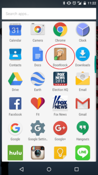
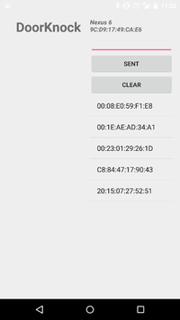
The DoorKnock app is designed to have a single home screen that initially displays a list of MAC addresses of the bluetooth devices within reach, a send and clear button, an input line to send signal, and an open space which displays text whenever it receives signal. The app is designed to give a notification to the user whenever it receives a signal from the bluetooth module that is connected to the SJSUOne board. The notification would display a short message to the user in the notification bar as well as alerting the user with a sound. The notification also appears with the app running in the background.
Android Application Development
The DoorKnock app consists of one main .java class named MainActivity.java and layout file that depicts the layout of the app named activity_main.xml. Initially, the one of the first things that we had to do was set the permissions under AndroidManifest.xml to allow the app to work with bluetooth. The two permissions that were added were the following: android.permissions.BLUETOOTH and android.permissions.BLUETOOH_ADMIN. Under the AndroidManifest.xml file, the main class was added under activity which allows us to edit the name of the app as well as the icon of the app that appears on the phone. We used Android Bluetooth application programming interface (API) such as BluetoothAdapter, BluetoothDevice, and BluetoothSocket.
BluetoothAdapter was used as an entry-point for any bluetooth communication. It allows the app to detect bluetooth devices which is how we were able to display a list of MAC addresses for our app. We use BluetoothAdaptor.ACTION_REQUEST_ENABLE to ensure bluetooth is turned on while calling startActivityForResult(). BluetoothAdaptor is also used to pair the device by using bluetoothAdaptor.getBondedDevices() which would return the set of bluetooth devices that are paired to the local adaptor.
protected void onStart() {
        super.onStart();

        //Turn ON BlueTooth if it is OFF
        if (!bluetoothAdapter.isEnabled()) {
            Intent enableIntent = new Intent(BluetoothAdapter.ACTION_REQUEST_ENABLE);
            startActivityForResult(enableIntent, REQUEST_ENABLE_BT);
        }

        setup();
    }
BluetoothDevice is created by the BluetoothAdaptor to allow it to create a connection with the device providing the following information: name, address, class, and bonding state. With that, we are capable of opening BluetoothSocket for communication with the bluetooth device.
private void setup() {
        Set<BluetoothDevice> pairedDevices = bluetoothAdapter.getBondedDevices();
        if (pairedDevices.size() > 0) {
            pairedDeviceArrayList = new ArrayList<BluetoothDevice>();

            for (BluetoothDevice device : pairedDevices) {
                pairedDeviceArrayList.add(device);
            }
.
.
.
BluetoothDevice device =(BluetoothDevice) parent.getItemAtPosition(position);
            Toast.makeText(MainActivity.this,
                  "Name: " + device.getName() + "\n"
                      + "Address: " + device.getAddress() + "\n"
                      + "BondState: " + device.getBondState() + "\n"
                      + "BluetoothClass: " + device.getBluetoothClass() + "\n"
                      + "Class: " + device.getClass(),
                            Toast.LENGTH_LONG).show();
To connect the BluetoothSocket to the HC-06 bluetooth module used in the SJSUOne board, we called BluetoothDevice.createRfcommSocketServiceRecord(myUUID). UUID is declared in the beginning as a string named myUUID. UUID are identified by software services used with RFCOMM sockets. The UUID that we used that was supported by the HC-06 device was "00001101-0000-1000-8000-00805F9B34FB". After, call bluetoothSocket.connect() to connect to the device. With that, that concludes the general idea of how to connect to the SJSUOne board via bluetooth with our Android app.
//declared earlier in the ''public class MainActivity''
    private UUID myUUID;
    private final String UUID_STRING_WELL_KNOWN_SPP =
            "00001101-0000-1000-8000-00805F9B34FB";
.
.
.
private BluetoothSocket bluetoothSocket = null;
        private final BluetoothDevice bluetoothDevice;

        private ThreadConnectBTdevice(BluetoothDevice device) {
            bluetoothDevice = device;

            try {
                bluetoothSocket = device.createRfcommSocketToServiceRecord(myUUID);
                textStatus.setText("bluetoothSocket: \n" + bluetoothSocket);
            } catch (IOException e) {
                // TODO Auto-generated catch block
                e.printStackTrace();
            }
        }
Testing & Technical Challenges
Issue #1: Piezo Sensor Sensitivity
We used several different types of Piezo vibration sensors before deciding to use this particular Piezo Element model. The other sensors seemed to generate a lot of noise and provided inconsistent resulting voltage values. It took thorough testing in real-time to decide on an appropriate minimum threshold value to use. If the threshold was too low, false positives would occur through ambient vibrations or noise in the readings. Yet, a threshold that is too high would not trigger the sensor during a knock, in some cases. Eventually, through trial and error, an appropriate threshold value was decided on.
Issue #2: Android App Testing Inconvenience
Because the app was designed to function only when connected to the HC-06 Bluetooth module, that was the only way to test whether or not the app was functioning properly. Since Andrew had the hardware components to the Bluetooth module and the vibration sensor, it was inconvenient at times when it comes to testing. We were only capable of testing the app once a week to analyze whether or not the feature worked. The solution to this was pretty simple and straightforward. Understanding the fact that we were going to meet on a weekly basis during our lab hours, we set milestones for ourselves to accomplish. That way, every time Friday came around, we would have completed our set of milestones to test our project accordingly.
Issue #3: Bluetooth Pairing
At first, we were using an Xbee shield Bluetooth module. However, despite verifying the correct initialization for the device, the Bluetooth module was not able to be discovered by external devices. We tried to connect with both a computer and a mobile phone, yet the module would not appear as a discoverable device. After more research, we decided to implement the HC-06 Bluetooth module instead, due to the fact that it is a widely used and universal device. Sure enough, after connecting it to the board and writing the driver, it was able to connect to devices successfully over Bluetooth.
Testing
Testing the Android Application
Testing the DoorKnock app required us to have both the app and the physical hardware of the vibration sensor present. It was impossible to determine whether or not something worked through the virtual devices provided by Android Studio. Most of the testing was done during the CmpE 146 lab on Fridays. The app was uploaded into the Nexus 6 smartphone via USB. THe phone had to be in development mode and had to had USB debugging enabled which could be done under settings. When running the program with Android Studio, it automatically picks up the Nexus 6 as the device to be connected to in which the app proceeds to be downloaded. From there, the phone is connected to the SJSUOne board to test all the features that we have set to accomplish and it then becomes a trial and error situation.
Testing the Knock Detection Interface
Once the sensor had been properly interfaced to the ADC, a minimum threshold value needed to be determined to signal a knock on the door. Some simple test code was developed to print out the results of the knock sensor in real time. Using these values displaying on the screen as we knocked, we could experiment with which values would be generated when there was a knock on the door. The key was to not make the value too low so that noise or accidental vibrations would signal a false "knock."
Testing the Bluetooth Communication
After the Bluetooth module had been interfaced using the UART bus, we could test if data could be sent over Bluetooth to a paired device. Test code was developed that would simply put a character of data on the TX line to send out to the HC-06 to transmit to the paired device. Using a computer that was connected to the module over Bluetooth, we could open op two serial terminals - one to monitor the data transmission from the LPC board and the other to monitor the data transmission to the paired device. After the correct functions were written and the computer was successfully paired, we could see data transmitted across the Bluetooth network.
Conclusion
Overall, this project was very exciting to work on. In all honesty, it gave us more motivation to work on this project compared to our own senior design projects. The doorknock idea was something that was fun and could potentially be used in a real life situation. One of the main things that we have learned to the development of an Android app. Neither one of us has ever developed an app before and it was definitely at great learning experience. We also became much more familiar with driver writing, UART bus communication, Bluetooth communication, FreeRTOS tasks, and sensor interfacing. The ability to receive data from a Bluetooth module to a smartphone was quite amazing. Combining all the individual modules to create our successful end product was a very rewarding experience.
Project Source Code
References
Acknowledgement
- Dr. Haluk Ozemek, for teaching us the background of embedded systems
- Preetpal Kang, for explaining applicable technical knowledge of FreeRTOS and drivers and for inspiring us to work hard on this project
- Connor Hergott, for assisting us with debugging the Android Application.
References Used
HC-06 Datasheet: https://www.olimex.com/Products/Components/RF/BLUETOOTH-SERIAL-HC-06/resources/hc06.pdf
Piezo Element Datasheet: https://www.sparkfun.com/datasheets/Sensors/Flex/p37e.pdf
Bluetooth | Android Developers: http://developer.android.com/guide/topics/connectivity/bluetooth.html
App Manifest | Android Developers: http://developer.android.com/guide/topics/manifest/manifest-intro.html
Intro to Bluetooth Application: https://developer.bluetooth.org/DevelopmentResources/Pages/Introduction-to-Bluetooth-Application-Development.aspx
Android Communicate to HC-06 Bluetooth Module: http://android-er.blogspot.com/2015/07/android-example-to-communicate-with.html
