Difference between revisions of "S15: MENL (Monster Encounter Night Light)"
(→Hardware Design) |
(→Grading Criteria) |
||
| (15 intermediate revisions by one other user not shown) | |||
| Line 1: | Line 1: | ||
| − | |||
| − | |||
| − | |||
| − | |||
| − | |||
| − | |||
| − | |||
| − | |||
| − | |||
| − | |||
| − | |||
| − | |||
== MENL (Monster Encounter Night Light) == | == MENL (Monster Encounter Night Light) == | ||
| Line 130: | Line 118: | ||
== Design & Implementation == | == Design & Implementation == | ||
| − | + | ||
=== Hardware Design === | === Hardware Design === | ||
| − | + | BLOCK Diagram: | |
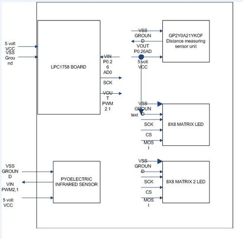
| + | The representation of the given block diagram influences the structure under which the embedded system was created. Two primary eight by eight light emitting diode displays exist for logical representation of action event when a person or thing sensed with respect to the motion sensor block. The distance sensor block is just a module to represent the measure distance with respect to a specific voltage as the the embedded board uses analog to digital functionality in order to calculate the given distance from an approaching source. | ||
| + | |||
| + | DISTANCE VS VOLTAGE GRAPH | ||
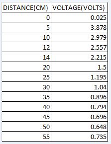
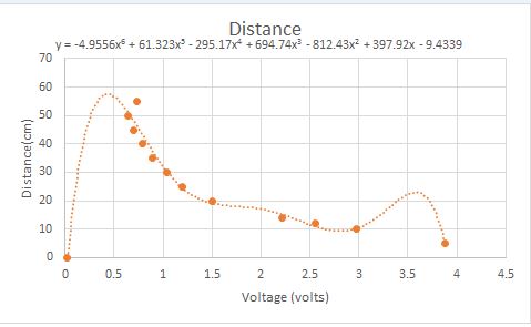
| + | By staring to take different distances from voltages using a ruler and a white paper with proper inputs connected as shown in block diagram, a graph was created. The intention was that as inputs were taken an output needed to be predicted at which voltage a distance could be read. The table that is shown demonstrates the findings. The equation in the graph is a formal description of the distance sensing unit behavior. | ||
[[File: S15_146_GRP3_LOOKUP_TABLE.jpg|500px|centre|thumb|Measurements conversion table]] | [[File: S15_146_GRP3_LOOKUP_TABLE.jpg|500px|centre|thumb|Measurements conversion table]] | ||
[[File: S15_146_GRP3_Distance_MEASUREMENTS.jpg|500px|centre|thumb|Distance Graph]] | [[File: S15_146_GRP3_Distance_MEASUREMENTS.jpg|500px|centre|thumb|Distance Graph]] | ||
| Line 139: | Line 131: | ||
=== Hardware Interface === | === Hardware Interface === | ||
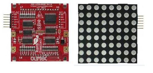
| − | + | For the parts required to complete our project, we opted on using GPIO for the motion sensor since we only needed to read a high and low signal from it to know if anyone was approaching MENL. The distance sensor provided us with an analog output which lead us the analog to digital libraries provided in FreeRtos. For the LED matrices, we tested it using the spi 1 library as well as we created our own SPI driver from our previous lab assigments. Both of them work exactly the same. Since the board came with a Pic device, all we needed to do was to send the correct byte through SPI. In addition, we needed a chip select to enable the output for the registers controlling the matrices. We used a GPIO signal for this. Similar to the SPI part, we used our own drivers, but decided to use the libraries to reduce the amount of code. All of this components work together are shown below. | |
[[File: S15_146_GRP3_LED_MATRIX_BACKandFront.jpg|500px |thumb|LED Matrix source: https://www.olimex.com/Products/Modules/LED/MOD-LED8x8RGB/open-source-hardware ]] | [[File: S15_146_GRP3_LED_MATRIX_BACKandFront.jpg|500px |thumb|LED Matrix source: https://www.olimex.com/Products/Modules/LED/MOD-LED8x8RGB/open-source-hardware ]] | ||
[[File: S15_146_GRP3_Motion_Sensor.jpg|500px |thumb|Motion Sensor source: https://www.sparkfun.com/products/13285]] | [[File: S15_146_GRP3_Motion_Sensor.jpg|500px |thumb|Motion Sensor source: https://www.sparkfun.com/products/13285]] | ||
| − | [[File: S15_146_GRP3_GRP3_Sensor.jpg|500px |thumb|Distance Sensor source: https://www.sparkfun.com/products/242]] | + | [[File: S15_146_GRP3_GRP3_Sensor.jpg|500px|centre |thumb|Distance Sensor source: https://www.sparkfun.com/products/242]] |
[[File: S15_146_GRP3_5V_POWERSUPPLY.jpg|500px|centre|thumb|5V Power Supply]] | [[File: S15_146_GRP3_5V_POWERSUPPLY.jpg|500px|centre|thumb|5V Power Supply]] | ||
[[File: S15_146_GRP3_Wiring_on_MENL.jpg|500px|centre|thumb|Wiring inside MENL]] | [[File: S15_146_GRP3_Wiring_on_MENL.jpg|500px|centre|thumb|Wiring inside MENL]] | ||
=== Software Design === | === Software Design === | ||
| − | + | In order to accomplish the task given from a customer to implement a system under which | |
| + | observations could be done at multiple times to check upon incoming sources, the following | ||
| + | guide will provide the privilege of describing the functionality with basic functions. | ||
| + | |||
| + | Part one distance sensing units: In order to make a fully functional embedded system the a distance sensor needed to | ||
| + | be implemented in order to know how long the source was away from the origin. Our device makes fully | ||
| + | functionality use of the analog to digital converter in which multiple voltage steps are measured | ||
| + | to transfer an analog voltage that is created from a led source inside the device that will bounce off white | ||
| + | spots and be seen as a digital converter on a microprocessor unit. | ||
| + | |||
| + | Part two motion sensing unit : | ||
| + | By making full use of the pir sensor that was bought in adrafuit.com, the motion sensor | ||
| + | enabled us to recognize if a source was approaching. As shown in the block diagram, the way under | ||
| + | which the device functions is that it returns a boolean voltage value as kinetic energy is sensed. | ||
| + | |||
| + | Part three display: | ||
| + | In order to output a signal or a reference of the status of sources, two 8x8 leds were used. | ||
| + | The method in software under which they behaved hold on a users actions. If detection was done two acting eyes would appear | ||
| + | and measure the distance, otherwise eyes would be closed. In the source files we are able to observe the use | ||
| + | of serial peripherical interface in order to clock in data to these devices as status signals provided feedback to the system. | ||
| + | |||
[[File: S15_146_GRP3_FLOWCHART.jpg|500px|centre|thumb|MOTION Sensor flowchart]] | [[File: S15_146_GRP3_FLOWCHART.jpg|500px|centre|thumb|MOTION Sensor flowchart]] | ||
=== Implementation === | === Implementation === | ||
| − | + | A Step by Step process of our implementation run like this | |
| + | * First the Motion Sensor will detect if anyone is around MENL, if no one is around it will display a white night light. The night light is created by sending 16 bytes, all of them 0xFF, this will turn on all of the lights in the rows in the LED matrices and since all are the same value the color will mix creating that white light. | ||
| + | * Second, if the Motion Sensor actually detects something, the distance sensor will be activated and will looked if anything is closed him. If nothing is closed him, the Led Matrices will display to closes eyes to indicate that MENL is alive but sleeping. The color purple is obtain by mixing blue and green when sending the bytes, therefore to have row one have the eyebrowns as purple, we would send 0x00, 0x7F, and 0xFE. | ||
| + | * Third, if the Motion Sensor detects something and the Distance Sensor can actually measure where it is, the LED Matrices will display two open yellow eyes, the color was chosen, to indicate a warning that somethings is around. Like in step two but with different bytes, in order to make yellow, we had to mix red and green, to do this just as an example we would something like 0xFF, 0xFF, and 0x00. | ||
| + | * Once everything has been completed, MILN will go back to night light mode. | ||
== Testing & Technical Challenges == | == Testing & Technical Challenges == | ||
| − | + | The first thing that we would tell ourselves if we were able to go back in time is to buy better devices. The sensors that we bought are really sensible and have delays and other problems that lead to obtaining the wrong outcome or the receive the outcome at different unexpected times. We notice this when testing. Our first test we did was the first time we were going to use the motion sensor in a while after having it tested a few weeks after it had arrived. We notice that it didn't work and it wasn't until we found out that sensor has an extra delay that makes the sensor take more then 40 seconds for it to start working properly. Also, the pins for the distance sensor are really sensitive and don't stay put. We notice this since it would sometimes measure the correct distance and a second later it will be negative. In addition, one they actually work, we did multiple test by moving our hands at different distances from both sensors. When we notice that it actually work, we installed the servo which we had been able to make it work by itself. However, we had to take it off from a few of the test that we had, ended up making MENL become FMENL, (flying monster encounter night light). Then, we retested everything again the night previous to the presentation, and notice that the distance sensor wasn't able to actually produce the night light since it kept detecting that there was something in front of it, when there was nothing at all. | |
| − | |||
| − | + | === My Issue #1 === | |
| + | We couldnt get the LCD Display to work. It seem to be a manufacturing problem, and it was too late to replace it so we drop it from the project. | ||
| − | === My Issue # | + | === My Issue #2 === |
| − | + | The servo seem to from time to time, not want to stop, this lead to wire wrapping problems and parts just flying away, so we decided to take it away. It was meant to make MENL rotate so it can look for other objects. | |
== Conclusion == | == Conclusion == | ||
| − | + | We had more problems then success in this project. Although, we though this will be a simple project, in reality we ended up having to drop a few things and changing projects because of the failure of fixing some problems. We learned about the uncertainty that this sensors bring, having timing issues ( specially from the motion sensor) that lead to late responses, which not only affected our testing but lead to hour and hours analyzing why we were getting the opposite reaction, when it was just the time. Overall, we learn about analog to digital conversion, learn a little bit more with I2C specially when we were working with the LCD Display, we worked with pulse width modulation when we working on the servos, and learn about the GPIO and SPI libraries offer from FreeRtos. At the end we should have done better, but we think we can actually complete this project, which is marketable to large population that buy toys just because is the new thing in town. | |
=== Project Video === | === Project Video === | ||
Upload a video of your project and post the link here. | Upload a video of your project and post the link here. | ||
| − | + | https://www.youtube.com/watch?v=Bbh2tejiG7Y&feature=youtu.be | |
[[File: S15_146_GRP3_Night_Light.jpg|500px|centre|thumb|Night Light]] | [[File: S15_146_GRP3_Night_Light.jpg|500px|centre|thumb|Night Light]] | ||
[[File: S15_146_GRP3_EYES_OPEN.jpg|500px|centre|thumb|Eyes Closed]] | [[File: S15_146_GRP3_EYES_OPEN.jpg|500px|centre|thumb|Eyes Closed]] | ||
| Line 175: | Line 191: | ||
=== Project Source Code === | === Project Source Code === | ||
| − | * [https://sourceforge.net/projects/ | + | * [https://sourceforge.net/projects/s15146grp3menl/files/?source=navbar Sourceforge Source Code Link] |
== References == | == References == | ||
=== Acknowledgement === | === Acknowledgement === | ||
| − | + | We would like to Ann Verakukala for providing us with one of the LED Matrices. | |
| + | Second we would like to thank all of the cmpe 146 personnel and students, they help us shape our projects to become MENL over other ideas that we had on mind. | ||
=== References Used === | === References Used === | ||
| − | + | We made all of our code with the libraries provided by FreeRtos and Drivers created from previous labs projects. | |
=== Appendix === | === Appendix === | ||
| − | + | * PIR Motion Sensor (JST) Datasheet: https://www.sparkfun.com/datasheets/Sensors/Proximity/SE-10.pdf | |
| + | * MOD-LED8x8RGB schematics: https://www.olimex.com/Products/Modules/LED/MOD-LED8x8RGB/resources/MOD-LED8x8RGB_Rev_B1_sch.pdf | ||
| + | * Infrared Proximity Sensor - Sharp GP2Y0A21YK : https://www.sparkfun.com/datasheets/Components/GP2Y0A21YK.pdf | ||
| + | * The CMPE 146 wiki page | ||
Latest revision as of 04:50, 26 May 2015
Contents
MENL (Monster Encounter Night Light)
Abstract
The monster encounter night light will have every single LED on when no motion is detected and no one is within distance of MELN. If someone is approaching MELN, depending on the distance of the object detected, The LED matrix will change into a pair of close eyes or a pair of open alert eyes.
Introduction
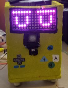
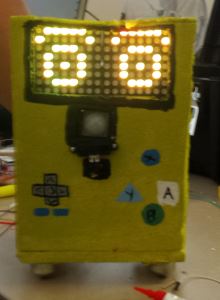
The MENL (Monster Encounter Night Light) is a children toy that will display multiple displays on the LED Matrices depending on the location and movement of objects around it. Once MENL had been turn on, the LED matrices will turn all on and dispay a bright white light to simulate a night light that children who are scared of the dark use. If some one is moving around MENL farther then 40 cm, The motion sensor will detect the presence of the moving object and the LED matrices will turn off and switch to the Display of two closed eyes, this simulates the change from night light form to Encounter mode. Once the moving object gets closer between the boundaries of the Distance Sensor, it will change the display to an alert MENL by having its eyes wide open and the color of the eyes change to yellow to emote a warning color.
Objectives
List of Objects to be completed:
1. Distance Sensor Interface
2. Motion Sensor Interface
3. Servo, skeleton rotation(cancelled)
4. LED Matrix SPI Interface
5. LCD Display I2C Interface (cancelled)
6. Communication between Sensors
7. Display result in LED Matrix
Team Members
- Moises Quinteros
- William Hernandez
Schedule
| Week# | Date | Task | Actual | |
|---|---|---|---|---|
| 1 | 4/13 | Order all required parts for project. | Completed, parts should arrive in a couple of weeks. | |
| 2 | 4/20 | Research on Sensors and work on overall design. | Completed. | |
| 3 | 4/27 | Research on Motion and Distance sensor and work on them functioning individually. | Completed, Problems Encountered= Motion Sensor seems to have a timing issues, responding late to motion. Distance sensor needs
an equation to translate the values obtain to centimeters. | |
| 4 | 5/4 | Buy extra LED Matrix, work on LCD display and LED Matrix display. | Completed: no. Problems Encountered: LCD display datasheets does not have the correct Slave Address,
we are working on it. LED Matrix doesnt seem to be displaying correct send Byte. | |
| 5 | 5/11 | Work on Skeleton and putting everything together. | Completed: Half Problems Encountered: LED was fixed, LCD Display does not want to work with correct Slave Address. | |
| 6 | 5/18 | Test, finish anything not yet completed. | Completed: half Problems Encountered: Drop LCD as it wasnt working and drop servo as it was unpredictable and would sometimes spin wildly. |
Parts List & Cost
| Item# | Desctiption# | Price# |
|---|---|---|
| Motion Sensor | PIR Motion Sensor (JST)
SEN-13285 |
$9.95 |
| Distance Sensor | Infrared Proximity Sensor - Sharp GP2Y0A21YK | $13.95 |
| LED Matrices | 2 MOD-LED8x8RGB | $30.50 ea |
| Cables | Female and Male jumper wires | $8 |
| SJ_One Board | SJ_One Board | $80 |
| Bread Board | Regular bread board | $5 |
| Capacitors, resistors , and other components | Multiples items for pull up resistors, power supply and other needs. | varies |
| Skeleton Components | Styro foam, Small Coasters, Screws, Super Glue | $35~ |
Design & Implementation
Hardware Design
BLOCK Diagram: The representation of the given block diagram influences the structure under which the embedded system was created. Two primary eight by eight light emitting diode displays exist for logical representation of action event when a person or thing sensed with respect to the motion sensor block. The distance sensor block is just a module to represent the measure distance with respect to a specific voltage as the the embedded board uses analog to digital functionality in order to calculate the given distance from an approaching source.
DISTANCE VS VOLTAGE GRAPH By staring to take different distances from voltages using a ruler and a white paper with proper inputs connected as shown in block diagram, a graph was created. The intention was that as inputs were taken an output needed to be predicted at which voltage a distance could be read. The table that is shown demonstrates the findings. The equation in the graph is a formal description of the distance sensing unit behavior.
Hardware Interface
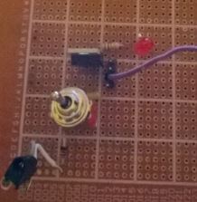
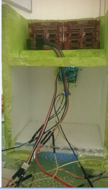
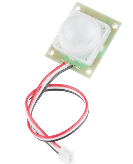
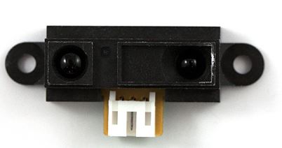
For the parts required to complete our project, we opted on using GPIO for the motion sensor since we only needed to read a high and low signal from it to know if anyone was approaching MENL. The distance sensor provided us with an analog output which lead us the analog to digital libraries provided in FreeRtos. For the LED matrices, we tested it using the spi 1 library as well as we created our own SPI driver from our previous lab assigments. Both of them work exactly the same. Since the board came with a Pic device, all we needed to do was to send the correct byte through SPI. In addition, we needed a chip select to enable the output for the registers controlling the matrices. We used a GPIO signal for this. Similar to the SPI part, we used our own drivers, but decided to use the libraries to reduce the amount of code. All of this components work together are shown below.
Software Design
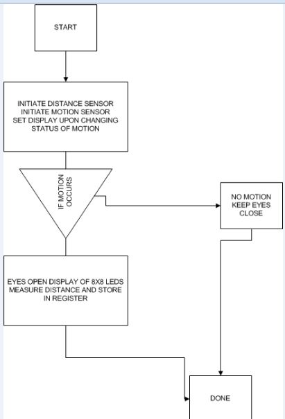
In order to accomplish the task given from a customer to implement a system under which observations could be done at multiple times to check upon incoming sources, the following guide will provide the privilege of describing the functionality with basic functions.
Part one distance sensing units: In order to make a fully functional embedded system the a distance sensor needed to be implemented in order to know how long the source was away from the origin. Our device makes fully functionality use of the analog to digital converter in which multiple voltage steps are measured to transfer an analog voltage that is created from a led source inside the device that will bounce off white spots and be seen as a digital converter on a microprocessor unit.
Part two motion sensing unit : By making full use of the pir sensor that was bought in adrafuit.com, the motion sensor enabled us to recognize if a source was approaching. As shown in the block diagram, the way under which the device functions is that it returns a boolean voltage value as kinetic energy is sensed.
Part three display: In order to output a signal or a reference of the status of sources, two 8x8 leds were used. The method in software under which they behaved hold on a users actions. If detection was done two acting eyes would appear and measure the distance, otherwise eyes would be closed. In the source files we are able to observe the use of serial peripherical interface in order to clock in data to these devices as status signals provided feedback to the system.
Implementation
A Step by Step process of our implementation run like this
- First the Motion Sensor will detect if anyone is around MENL, if no one is around it will display a white night light. The night light is created by sending 16 bytes, all of them 0xFF, this will turn on all of the lights in the rows in the LED matrices and since all are the same value the color will mix creating that white light.
- Second, if the Motion Sensor actually detects something, the distance sensor will be activated and will looked if anything is closed him. If nothing is closed him, the Led Matrices will display to closes eyes to indicate that MENL is alive but sleeping. The color purple is obtain by mixing blue and green when sending the bytes, therefore to have row one have the eyebrowns as purple, we would send 0x00, 0x7F, and 0xFE.
- Third, if the Motion Sensor detects something and the Distance Sensor can actually measure where it is, the LED Matrices will display two open yellow eyes, the color was chosen, to indicate a warning that somethings is around. Like in step two but with different bytes, in order to make yellow, we had to mix red and green, to do this just as an example we would something like 0xFF, 0xFF, and 0x00.
- Once everything has been completed, MILN will go back to night light mode.
Testing & Technical Challenges
The first thing that we would tell ourselves if we were able to go back in time is to buy better devices. The sensors that we bought are really sensible and have delays and other problems that lead to obtaining the wrong outcome or the receive the outcome at different unexpected times. We notice this when testing. Our first test we did was the first time we were going to use the motion sensor in a while after having it tested a few weeks after it had arrived. We notice that it didn't work and it wasn't until we found out that sensor has an extra delay that makes the sensor take more then 40 seconds for it to start working properly. Also, the pins for the distance sensor are really sensitive and don't stay put. We notice this since it would sometimes measure the correct distance and a second later it will be negative. In addition, one they actually work, we did multiple test by moving our hands at different distances from both sensors. When we notice that it actually work, we installed the servo which we had been able to make it work by itself. However, we had to take it off from a few of the test that we had, ended up making MENL become FMENL, (flying monster encounter night light). Then, we retested everything again the night previous to the presentation, and notice that the distance sensor wasn't able to actually produce the night light since it kept detecting that there was something in front of it, when there was nothing at all.
My Issue #1
We couldnt get the LCD Display to work. It seem to be a manufacturing problem, and it was too late to replace it so we drop it from the project.
My Issue #2
The servo seem to from time to time, not want to stop, this lead to wire wrapping problems and parts just flying away, so we decided to take it away. It was meant to make MENL rotate so it can look for other objects.
Conclusion
We had more problems then success in this project. Although, we though this will be a simple project, in reality we ended up having to drop a few things and changing projects because of the failure of fixing some problems. We learned about the uncertainty that this sensors bring, having timing issues ( specially from the motion sensor) that lead to late responses, which not only affected our testing but lead to hour and hours analyzing why we were getting the opposite reaction, when it was just the time. Overall, we learn about analog to digital conversion, learn a little bit more with I2C specially when we were working with the LCD Display, we worked with pulse width modulation when we working on the servos, and learn about the GPIO and SPI libraries offer from FreeRtos. At the end we should have done better, but we think we can actually complete this project, which is marketable to large population that buy toys just because is the new thing in town.
Project Video
Upload a video of your project and post the link here.
https://www.youtube.com/watch?v=Bbh2tejiG7Y&feature=youtu.be
Project Source Code
References
Acknowledgement
We would like to Ann Verakukala for providing us with one of the LED Matrices. Second we would like to thank all of the cmpe 146 personnel and students, they help us shape our projects to become MENL over other ideas that we had on mind.
References Used
We made all of our code with the libraries provided by FreeRtos and Drivers created from previous labs projects.
Appendix
- PIR Motion Sensor (JST) Datasheet: https://www.sparkfun.com/datasheets/Sensors/Proximity/SE-10.pdf
- MOD-LED8x8RGB schematics: https://www.olimex.com/Products/Modules/LED/MOD-LED8x8RGB/resources/MOD-LED8x8RGB_Rev_B1_sch.pdf
- Infrared Proximity Sensor - Sharp GP2Y0A21YK : https://www.sparkfun.com/datasheets/Components/GP2Y0A21YK.pdf
- The CMPE 146 wiki page
