Difference between revisions of "S15: Hovercopter"
Proj user3 (talk | contribs) (→Design & Implementation) |
(→Testing & Technical Challenges) |
||
| (124 intermediate revisions by 4 users not shown) | |||
| Line 1: | Line 1: | ||
| − | |||
| − | |||
| − | |||
| − | |||
| − | |||
| − | |||
| − | |||
| − | |||
| − | |||
| − | |||
| − | |||
| − | |||
== Hovercopter == | == Hovercopter == | ||
| Line 17: | Line 5: | ||
= Introduction = | = Introduction = | ||
| − | Self-stabilization of quadcopters requires that all four rotors are working together to correct themselves according to the gyroscope reading. | + | Self-stabilization of quadcopters requires that all four rotors are working together to correct themselves according to the gyroscope reading. Our goal for this lab is to get the quadcopter to self-stabilize, and hold its altitude. This is not a simple task. Getting the quadcopter to stabilize on the pitch and roll axis individually is already a huge task alone, but to get them both to hover with both working simultaneously is tough. The flight controller is programmed into the SJSUOne board. Everything ranging from stabilization to remote control is handled on this board. A PID algorithm is used to handle stabilization. This algorithm has been provided and written. Most of our code configuration lied within setting proper normalized values of the remote and to get the proper frequency settings. We spent the bulk of our time finding proper PID coefficients to get the proper stabilization. We have used several different methods including brute force, Ziegler-Nichols, and Cohen-Coon methods. |
| − | The flight controller is programmed into the SJSUOne board. Everything ranging from stabilization to remote control is handled on this board. A PID algorithm is used to handle stabilization. This algorithm has been provided and written. Most of our code configuration lied within setting proper normalized values of the remote and to get the proper frequency settings. We spent the bulk of our time finding proper PID coefficients to get the proper stabilization. We have used several different methods including brute force, Ziegler-Nichols, and Cohen-Coon methods. | + | |
| + | The default code for our project allows for the quadcopter to fly in a "+" formation where the north motor is the true north. However, we have chosen to fly in the "x" formation because we plan to add an FPV camera to it. This is a simple 4-line tweak in the computeThrottleValues function in flight_stabilizer.cpp. True north can be computed by adding the pitch north (default north) and roll east (default east) together. This is our "x" formation north. The user may configure this however way he or she wants however. | ||
== Objectives == | == Objectives == | ||
| Line 133: | Line 122: | ||
=== Hardware Design === | === Hardware Design === | ||
| − | |||
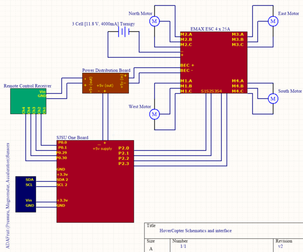
To make the quadcopter a SJOne board is used on which the flight controller software is developed. This board reads the sensors values and generates the PWM (Pulse Width Modulation) pulses to drive the four motors. | To make the quadcopter a SJOne board is used on which the flight controller software is developed. This board reads the sensors values and generates the PWM (Pulse Width Modulation) pulses to drive the four motors. | ||
| Line 143: | Line 131: | ||
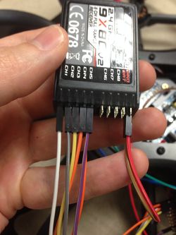
The ADAFruit sensor board uses the I^2 C bus, so it is connected to SDA2 and SCL2 signals of SJOne board. The remote control receiver is connected to the GPIO pins as follows: | The ADAFruit sensor board uses the I^2 C bus, so it is connected to SDA2 and SCL2 signals of SJOne board. The remote control receiver is connected to the GPIO pins as follows: | ||
| − | P0.0 | + | {| class="wikitable" |
| + | |- | ||
| + | ! scope="col"|No. | ||
| + | ! scope="col"|Pin | ||
| + | ! scope="col"|RC Channel | ||
| + | ! scope="col"|Receiver Channel | ||
| + | ! scope="col"|Description | ||
| + | |- | ||
| + | | scope="row"|1||P0.0||1||2||Pitch - Grey Wire | ||
| + | |- | ||
| + | | scope="row"|2||P0.1||2||1||Roll - White Wire | ||
| + | |- | ||
| + | | scope="row"|3||P0.29||3||4||Yaw - Orange Wire | ||
| + | |- | ||
| + | | scope="row"|4||P0.30||4||3||Throttle - Grey Wire | ||
| + | |- | ||
| + | | scope="row"|5||P2.6||5|| ||Arm/Disarm | ||
| + | |- | ||
| + | |} | ||
| − | |||
| − | |||
| − | |||
| − | |||
| − | |||
| − | |||
| − | |||
The four motors are connected to the PWM enabled GPIO ports of the SJOne board in following order: | The four motors are connected to the PWM enabled GPIO ports of the SJOne board in following order: | ||
| − | P2.0 | + | {| class="wikitable" |
| + | |- | ||
| + | ! scope="col"|No. | ||
| + | ! scope="col"|Pin | ||
| + | ! scope="col"|Motor Direction | ||
| + | |- | ||
| + | | scope="row"|1||P2.0||North | ||
| + | |- | ||
| + | | scope="row"|2||P2.1||South | ||
| + | |- | ||
| + | | scope="row"|3||P2.2||East | ||
| + | |- | ||
| + | | scope="row"|4||P2.3||West | ||
| + | |- | ||
| + | |} | ||
| − | |||
| − | |||
| − | + | [[File: S15_146_G1_Sch_v2.0.PNG|600px|center|thumb|Figure. 1 Hardware Design]] | |
| − | |||
| − | |||
| − | [[File: | ||
=== Remote Control Transmitter & Receiver === | === Remote Control Transmitter & Receiver === | ||
| − | |||
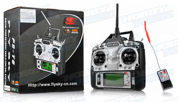
The remote control transmitter is responsible for transmitting the desired throttle, pitch, roll, and yaw angles. We chose the FlySky FS-T6 model, which has 6 available channels. The operating frequency is 2.4GHz and the remote comes with many features including a backlit LCD. The channels and their associated operation are : | The remote control transmitter is responsible for transmitting the desired throttle, pitch, roll, and yaw angles. We chose the FlySky FS-T6 model, which has 6 available channels. The operating frequency is 2.4GHz and the remote comes with many features including a backlit LCD. The channels and their associated operation are : | ||
| Line 181: | Line 188: | ||
Channel 6 - Arm/Disarm | Channel 6 - Arm/Disarm | ||
| + | [[File: S15 146 G1 flysky.jpg|350px|center|thumb|Figure 2. Remote Controller]] | ||
=== Motors === | === Motors === | ||
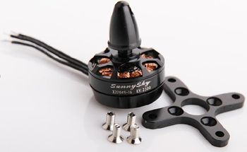
Brushless motors are perfect for quadcopters because of their superior efficiency. They are much more powerful than conventional brushed motors and less electrical energy is wasted. The fewer mechanical parts result in reduced operational noise and quieter performance. Brushless motors work by producing magnetic fields to produce electric charges. Magnets will attempt to align, thus, causing the motor to spin. A continuous flow on multiple magnets will result in constant spinning depending on the signals sent to the device. Different currents are flowing through different coils making the motor shaft spin. The speed of the spinning motor shaft is controlled by an ESC (electronic speed controller) and is performed by switching the motor coils on or off rapidly at different, but synchronized, times. | Brushless motors are perfect for quadcopters because of their superior efficiency. They are much more powerful than conventional brushed motors and less electrical energy is wasted. The fewer mechanical parts result in reduced operational noise and quieter performance. Brushless motors work by producing magnetic fields to produce electric charges. Magnets will attempt to align, thus, causing the motor to spin. A continuous flow on multiple magnets will result in constant spinning depending on the signals sent to the device. Different currents are flowing through different coils making the motor shaft spin. The speed of the spinning motor shaft is controlled by an ESC (electronic speed controller) and is performed by switching the motor coils on or off rapidly at different, but synchronized, times. | ||
| − | [[File: S15 146 G1 sunnysky.jpg|350px|center]] | + | [[File: S15 146 G1 sunnysky.jpg|350px|center|thumb|Figure 3. Brushless Motors]] |
=== Electronic Speed Controller (ESC) === | === Electronic Speed Controller (ESC) === | ||
| − | + | ||
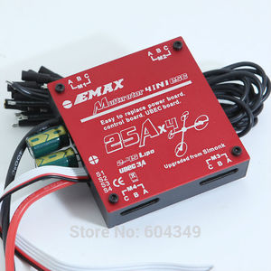
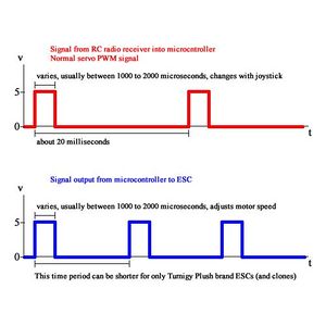
| − | [[File: S15 146 G1 emax.jpg|300px|center]] | + | The ESC is an plays an integral part in controlling the motors. They vary the speed of the motors by feeding it PWM signals at varying pulse widths. Our ESC runs at about 50 Hz with pulse widths that range from 1 ms to 2 ms. 1 ms turns off the motor input while 2 ms makes the motor run at max speed. The EMAX 4-in-1 is programmable, and has several different parameters for the user to configure. We have chosen to use the recommended settings that came in the EMAX manual. |
| + | |||
| + | [[File: S15 146 G1 emax.jpg|300px|center|thumb|Figure 4. Electronic Speed Control]] | ||
=== IMU Sensor === | === IMU Sensor === | ||
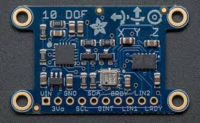
| − | + | The IMU (Intertial Measurement Unit) is a sensor that measures the orientation of the quadcopter. IMU's are important because they provide the necessary information needed to control the quadcopter. Included in the IU is an accelerometer, a gyroscope, and a magnetometer. This is the device that is used in conjunction with the SJSUOne board to compute proper PID values and for the remote control to request angles for pitch, roll, and yaw. In our case, Y points to the north by default. The SJSUOne board reads these values and adjusts the quadcopter accordingly. | |
| − | [[File: S15 146 G1 adafruit.jpeg|300px|center]] | + | [[File: S15 146 G1 adafruit.jpeg|300px||thumb|center|Fig. 5 Inertial Measurement Unit]] |
=== SJOne Flight Controller === | === SJOne Flight Controller === | ||
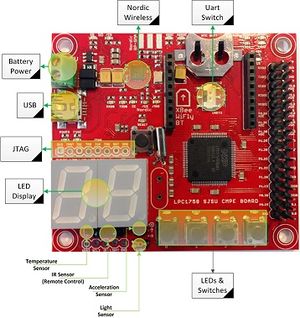
| − | + | The SJOne board is programmed and configured to be the flight controller of the quadcopter. The RC receiver, the sensor, and the ESC are all hooked up to the board. Each of these devices are actively working together and are controlled by the board. The receiver takes input from the RC and outputs it into the SJOne board. The board will process the requested PWM and will use this information to control the ESC. It will also process the requested angle of pitch and roll. The sensor readings will be used to process both the requested angle from the RC, and to process the flight stabilization calculations. This microcontroller controls every aspect required for the quadcopter to fly. Every action must first go through the SJOne board. FreeRTOS is extensively used on the board. Many critical actions such as remote control and flight stabilization are set up as tasks. The board will determine the priority given to each task. | |
| − | [[File: Sjone board.jpg|300px|center]] | + | |
| + | [[File: Sjone board.jpg|300px|center|thumb|Figure 6. SJOne Board]] | ||
=== Hardware Interface === | === Hardware Interface === | ||
| − | |||
| − | |||
Communication protocols used : | Communication protocols used : | ||
#'''UART''' - Serial communication and telemetry. | #'''UART''' - Serial communication and telemetry. | ||
| + | #'''PPM''' (Pulse Position Modulation) - Sequence of 6 channels of remote control transmitter signals into receiver on the quadcopter. | ||
| + | #'''Interrupts''' - Usage of the GPIO ports on the SJSU One board and the timer API to capture the PPM signals from the remote control transmitter to receiver. | ||
#'''PWM''' (Pulse Width Modulation) - Decoding remote control signals into pulse signals the ESC's can use to drive the motors | #'''PWM''' (Pulse Width Modulation) - Decoding remote control signals into pulse signals the ESC's can use to drive the motors | ||
| − | + | [[File: S15 146 G1 pwmsample.jpg|300px|center|thumb|Figure 7. PWM Samples]] | |
=== Software Design === | === Software Design === | ||
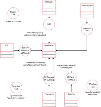
Our software utilizes object oriented programming (OOP) concepts. There are many types of "objects" which hold data in our system. For example, mFlightControllerAngles holds the current setpoint angles for all axis, mCurrentAngles holds the current x, y, and z-axis angles, and mMotorValues holds the motor values which will be applied to the motors. There are several different classes which separate the different functions in the system. The lowest level class, MotorControllerIface is an abstract class which contains undefined virtual methods. These virtual methods are defined in inherited classes which will use them. The FlightStabilizer class is responsible for controlling flight parameters using the sensor data and controlling lower-level flight logic. The highest level class, QuadcopterBase, is defined for high-level flight logic such as autonomous GPS flying. | Our software utilizes object oriented programming (OOP) concepts. There are many types of "objects" which hold data in our system. For example, mFlightControllerAngles holds the current setpoint angles for all axis, mCurrentAngles holds the current x, y, and z-axis angles, and mMotorValues holds the motor values which will be applied to the motors. There are several different classes which separate the different functions in the system. The lowest level class, MotorControllerIface is an abstract class which contains undefined virtual methods. These virtual methods are defined in inherited classes which will use them. The FlightStabilizer class is responsible for controlling flight parameters using the sensor data and controlling lower-level flight logic. The highest level class, QuadcopterBase, is defined for high-level flight logic such as autonomous GPS flying. | ||
| + | [[File: S15_146_G1_Sft_v1.0.jpg|350px|center|thumb|Figure 9. Software Diagram]] | ||
| + | |||
==== PID Controller ==== | ==== PID Controller ==== | ||
| − | |||
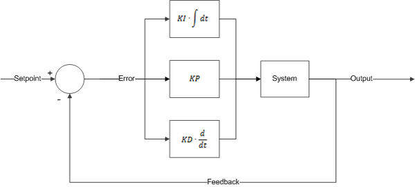
PID (proportional, integral, and derivative) is a closed-loop control system that tries to get results closer to the desired setpoint by adjusting the inputs of the system. The PID controller calculates an error, which is the difference between the measured variable and desired setpoint. The PID controller tries to minimizes the error throughout the operation. Our system takes the measured sensor data and compares against expected values (from the remote control) to alter the PWM output which will be applied to the ESC's and motors. The PID controller contains 3 separate parameters - proportional, integral, and derivative. P depends on the present, I on the accumulation of past errors, and D is a prediction of future errors based on the current rate of change. A higher P tries harder to stabilize itself - which can result in overshoot if too high. I attempts to reduce error based on past errors. The longer the error persists, then the more I will attempt to correct itself. Too much I can result in oscillations at lower frequencies. D attempts to dampen the system and prevent fast movements. However, too high of a D will also introduce oscillations. | PID (proportional, integral, and derivative) is a closed-loop control system that tries to get results closer to the desired setpoint by adjusting the inputs of the system. The PID controller calculates an error, which is the difference between the measured variable and desired setpoint. The PID controller tries to minimizes the error throughout the operation. Our system takes the measured sensor data and compares against expected values (from the remote control) to alter the PWM output which will be applied to the ESC's and motors. The PID controller contains 3 separate parameters - proportional, integral, and derivative. P depends on the present, I on the accumulation of past errors, and D is a prediction of future errors based on the current rate of change. A higher P tries harder to stabilize itself - which can result in overshoot if too high. I attempts to reduce error based on past errors. The longer the error persists, then the more I will attempt to correct itself. Too much I can result in oscillations at lower frequencies. D attempts to dampen the system and prevent fast movements. However, too high of a D will also introduce oscillations. | ||
| + | [[File: S15 146 G1 PID1.png||600px|center|thumb|Figure 19. PWM Algorithm Map]] | ||
== Implementation == | == Implementation == | ||
| Line 234: | Line 247: | ||
#Else, scale from -45 degrees to +45 degrees by using a separate scaling factor and subtracting factor. Apply values for requested flight angles. | #Else, scale from -45 degrees to +45 degrees by using a separate scaling factor and subtracting factor. Apply values for requested flight angles. | ||
#Set limits and noise margins for robustness. | #Set limits and noise margins for robustness. | ||
| + | |||
| + | == Integration == | ||
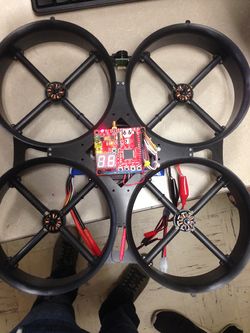
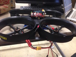
| + | Below are pictures of the actual design and integration of the entire system. | ||
| + | |||
| + | [[File: S15 146 G1 des1.JPG|250px]] | ||
| + | [[File: S15 146 G1 PowerSensor.JPG|250px]] | ||
| + | [[File: S15 146 G1 emptyframe.JPG|250px]] | ||
| + | [[File: S15 146 G1 Receiver.JPG|250px]] | ||
| + | [[File: S15 146 G1 final1.JPG|250px]] | ||
| + | [[File: S15 146 G1 IMG 2234.JPG|250px]] | ||
== Testing & Technical Challenges == | == Testing & Technical Challenges == | ||
| − | === Issue #1 === | + | === PID Tuning Testing Methods === |
| + | There are several ways to tune for PID. We have found Oscar Liang's blog on multicopters to be very helpful. http://blog.oscarliang.net/. | ||
| + | |||
| + | ==== Brute Force ==== | ||
| + | Before trying the Ziegler-Nichols or Cohen-Coon methods, we tried different brute force methods of tuning. First P, I, and D are set to 0. P is then gradually increased until there is a stable oscillation. I is then slowly increased until the quadcopter can quickly stabilize itself. After P and I are tuned, D can be tuned as well, however, D values may have an effect on P and I. After D is tuned, P and I may need to be retuned again. The brute force method is very straight forward, but it is very time consuming, and good results take a lot of time to acquire. | ||
| + | |||
| + | ==== Cohen-Coon ==== | ||
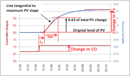
| + | The Cohen-Coon method of tuning corrects the slow, steady-state response. This method is an offline method of tuning, meaning that a step change is introduced to the system once it is at steady state. The output is then measured based on the time constant and the time delay. The response can be used to evaluate the initial control parameters. Shown in the first picture, the delay time is td and tau is the time constant to reach 63% of the process input. | ||
| + | [[File: S15 146 G1 StepTestcohen.png|center|450px]] | ||
| + | [[File: S15 146 G1 CohenCoonRules1 copy.jpg|center|450px]] | ||
| + | [[File: S15 146 G1 Cohen coon.jpg|center|450px]] | ||
| + | ==== Ziegler-Nichols ==== | ||
| + | The Ziegler-Nichols tuning method was developed in the 1940's to obtain control parameters. The closed-loop tuning method, which we chose to use, involves finding the ultimate gain value, Ku, and the ultimate period of oscillation, Pu, to calculate Kc. It is a simple method of tuning PID controllers and can be refined and tuned further for better system response. The ultimate gain value, Ku, is found by finding the value of the proportional-only gain that causes the control loop to oscillate indefinitely at steady state. The parameters I and D are set to 0. The ultimate period, Pu, is the time required to complete one full oscillation while the system is at steady state. These two parameters alone are used to find the gain coefficients P, I, and D. An important thing to note here is the fact that these are only to be considered for initial values for further testing and fine tuning. Notice that there is still overshoot and an underdamped system response is given. It is important for the quadcopter to behave as a critically damped system. | ||
| + | [[File: S15 146 G1 ZN.png|center|450px]] | ||
| + | [[File: S15 146 G1 Ziegler nichols tuning.jpg|center|450px]] | ||
| + | |||
| + | ==== Stable PID Output ==== | ||
| + | Upon completion of a stable quadcopter the graph produced below dictates a stable response in the PID control system. The random spikes most likely occurred from ground wind turbulences or the fact that we had a torn propeller. | ||
| + | [[File:SP 15 HoverCopter Best PID graph.png|center|450px]] | ||
| + | === Issues Faced === | ||
| + | |||
| + | ==== Issue #1 ==== | ||
Issue: We first had inconsistent motor/propeller spinning. They were not spinning with normal behavior so we traced it back to the values that are applied to the motor from the remote control signals. The values decoded from the remote controls signals were incorrect. The ESC"s accept PWM servo pulses upon calibration and we initially had the SJSU One board outputting PWM duty cycle signals to the ESC. We reworked the remote control decoding functions to correct PWM pulses ranging from 1ms to 2ms wide pulses. | Issue: We first had inconsistent motor/propeller spinning. They were not spinning with normal behavior so we traced it back to the values that are applied to the motor from the remote control signals. The values decoded from the remote controls signals were incorrect. The ESC"s accept PWM servo pulses upon calibration and we initially had the SJSU One board outputting PWM duty cycle signals to the ESC. We reworked the remote control decoding functions to correct PWM pulses ranging from 1ms to 2ms wide pulses. | ||
Result: The result was smooth operation of motors/propellers when throttle was applied from the remote control to the SJSU One board. | Result: The result was smooth operation of motors/propellers when throttle was applied from the remote control to the SJSU One board. | ||
| − | === Issue #2 === | + | ==== Issue #2 ==== |
Issue: During the week of 4/24/15 to 4/29/15, we had remote control transmitter issues. It started out with random spikes in throttle pulse widths. We fixed the random spikes by adding control in our software, but eventually the throttle had no response. Change in the joystick would have no effect on the actual pulse width received from the receiver. | Issue: During the week of 4/24/15 to 4/29/15, we had remote control transmitter issues. It started out with random spikes in throttle pulse widths. We fixed the random spikes by adding control in our software, but eventually the throttle had no response. Change in the joystick would have no effect on the actual pulse width received from the receiver. | ||
Result: Our solution was to order a different brand, especially not the Turnigy 9x. We opted for the FlySky FS-T6 remote control transmitter. So far, it has better response, light up display, and ability to adjust throttle curve which the Turnigy didn't have. Another issue that we have faced though, is the channel that we want our roll to be on does no work, instead, we have replaced the yaw channel with roll as a temporary fix. | Result: Our solution was to order a different brand, especially not the Turnigy 9x. We opted for the FlySky FS-T6 remote control transmitter. So far, it has better response, light up display, and ability to adjust throttle curve which the Turnigy didn't have. Another issue that we have faced though, is the channel that we want our roll to be on does no work, instead, we have replaced the yaw channel with roll as a temporary fix. | ||
| + | |||
| + | ==== Issue #3 ==== | ||
| + | Issue: After spending many hours, we were able to get the quadcopter to stabilize on both pitch and roll individually. However, when trying to fly, it tends to lean too far to one side. One fix is to manually input pitch or roll depending on the direction of the flight. This is not a good fix though, as it is still unstable. | ||
| + | |||
| + | Result: We believe that this error is a trimming error as opposed to a PID error. The quadcopter does not oscillate uncontrollably, rather, it just leans to one side too much. | ||
== Conclusion == | == Conclusion == | ||
| − | + | We have learned many valuable things from this project. Besides team-work and process planning, we learned many things that can be applied to future work. Before this project, we had no experience with remote control PWM signal processing, PID feedback control, or flying with devices. This project has expanded our tool-set because we broadened our experience with real-world applications. Also, we learned that PID tuning is not just a simple plug and play process. Majority of the time spent on the project was devoted towards PID tuning. You can have a set of PID coefficient gains that are optimal for a smooth or aggressive flight and you won't know how it actually reacts until you start flying it. For example, we made a test-bed rig for tuning on 1 axis at a time and were able to log many different sets of PID values that seemed suitable for flying. Actually flying it on its own is a completely different story. Three different axis running plus outside disturbances such as wind and turbulence will have an affect on the real-time operation and flying. Another important thing we learned from this project is signal processing. We learned how to encode and decode signals from one form to another. What we have ultimately learned from this project is that planning and testing phases are crucial for a project, especially a quadcopter, to run well. Without a doubt, we will continue to utilize knowledge from this project towards other future projects. | |
=== Project Video === | === Project Video === | ||
| + | |||
| + | Most Stable Outdoor Flying : | ||
| + | https://www.youtube.com/watch?v=JQmJV1W8POk | ||
| + | |||
| + | Hand Gesture Detection (Senior Project Add-on) : | ||
| + | https://www.youtube.com/watch?v=w8gsY9lP0CI&feature=youtu.be | ||
| + | |||
| + | First Outdoor Test-run on a windy day | ||
| + | https://www.youtube.com/watch?v=ufwh9sUGdOk | ||
| + | |||
| + | Second Outdoor Test-run on the same windy day | ||
| + | https://www.youtube.com/watch?v=on9adUZsdkk | ||
| + | |||
Initial testing of P values : | Initial testing of P values : | ||
https://www.youtube.com/watch?v=IqSVVo5YJBs&feature=youtu.be | https://www.youtube.com/watch?v=IqSVVo5YJBs&feature=youtu.be | ||
| Line 272: | Line 334: | ||
http://blog.oscarliang.net/quadcopter-pid-explained-tuning/ | http://blog.oscarliang.net/quadcopter-pid-explained-tuning/ | ||
| − | + | http://blog.opticontrols.com/archives/383 | |
| − | + | ||
| + | http://robotics.stackexchange.com/questions/167/what-are-good-strategies-for-tuning-pid-loops | ||
Latest revision as of 05:42, 6 December 2015
Contents
Hovercopter
Abstract
The goal of our project is to design a quadcopter that is capable of self-stabilizing with altitude holding capabilities. The software will use a PID control algorithm to stabilize the motor speeds according to the accelerometer and gyroscope sensor values. The hardware will consist of interfacing the SJSU One board with an Adafruit 10-DOF sensor, remote control receiver, five sonar sensors, an electronic speed controller (ESC), and the four motors. The quadcopter will be able to avoid obstacles using the sonar sensors.
Introduction
Self-stabilization of quadcopters requires that all four rotors are working together to correct themselves according to the gyroscope reading. Our goal for this lab is to get the quadcopter to self-stabilize, and hold its altitude. This is not a simple task. Getting the quadcopter to stabilize on the pitch and roll axis individually is already a huge task alone, but to get them both to hover with both working simultaneously is tough. The flight controller is programmed into the SJSUOne board. Everything ranging from stabilization to remote control is handled on this board. A PID algorithm is used to handle stabilization. This algorithm has been provided and written. Most of our code configuration lied within setting proper normalized values of the remote and to get the proper frequency settings. We spent the bulk of our time finding proper PID coefficients to get the proper stabilization. We have used several different methods including brute force, Ziegler-Nichols, and Cohen-Coon methods.
The default code for our project allows for the quadcopter to fly in a "+" formation where the north motor is the true north. However, we have chosen to fly in the "x" formation because we plan to add an FPV camera to it. This is a simple 4-line tweak in the computeThrottleValues function in flight_stabilizer.cpp. True north can be computed by adding the pitch north (default north) and roll east (default east) together. This is our "x" formation north. The user may configure this however way he or she wants however.
Objectives
Our objectives include the following:
- Self-balancing and self-stabilizing system with the ability to pitch forward, pitch backward, roll left, roll right, yaw left, and yaw right.
- Altitude hold with the use of a sonar sensor and obstacle avoidance with the use of 4 sonar sensors.
- Clear unobstructed communication from the remote control transmitter to the remote control receiver located on the system.
- Arm/Disarm
- Kill switch
- SD Card logging
Team Members & Responsibilities
- Arlen Eskandari
- Jonathon Hongpananon
- Phillip Tran
Schedule
| Week# | Start Date | End Date | Task | Status | Actual Completion Date |
|---|---|---|---|---|---|
| 1 | 4/14/2015 | 4/20/2015 | Correctly route North, South, East, and West pins to their respective motor/ESC wire locations. Start testing and determining a proper P value, then I, then D value. | Complete | 4/20/15 |
| 2 | 4/21/2015 | 4/27/2015 | Continuation of determining Proportional, Integral, and Derivative values. | Complete | 4/30/15 |
| 3 | 4/28/2015 | 5/4/2015 | Install sonar sensors for future altitude holding. Use pid tune task which iterates through a range of selected P, I, and D values. This will log the PID output with the respective PID values onto the SD card. We will use Excel to graph the output to determine the smoothest curve with no overdamp/underdamp effect. | Complete | 5/7/15 |
| 4 | 5/5/2015 | 5/11/2015 | Continuation of PID fine Tuning | Complete | 5/23/15 |
| 5 | 5/12/2015 | 5/18/2015 | Fix gyroscope sensor readings and tune PID values for yawThrottle. | Complete | 5/15/15 |
| 6 | 5/19/2015 | 5/22/2015 | Test complete movement consisting of pitch forward, pitch backward, roll right, and roll left. | Complete | 5/21/15 |
Parts List & Cost
Give a simple list of the cost of your project broken down by components. Do not write long stories here.
| Qty | Description | Manufacturer | Part Number | Total Cost |
|---|---|---|---|---|
| 1 | FPV 4-Axis Quadcopter Frame kit w/ Protective Guard | UFO | $41.00 | |
| 1 | Brushless 25A SimonK 4-in-1 ESC Built-in UBEC | Emax | 24A*4-UBEC | $29.00 |
| 4 | 6045 Carbon Nylon Propellers | Gemfan | $4.00 | |
| 1 | SJOne Board | Preet | LPC1758 SJSU Board | $80.00 |
| 1 | 9X 9ch Transmitter w/ Module & 8ch Receiver | Turnigy | TX-9X-M2 | $60.00 |
| 1 | x2204 2300kv Brushless Motors - set of 4 | SunnySky | SNS-X2204S-KV2300 | $63.00 |
| 2 | 4000mAh 3S 30C Lipo Battery Pack | Turnigy | T4000.3S.30 | $22.00 |
| 1 | 50W 5A Balancer Charger | Hobbyking | ECO6 | $19.00 |
| 1 | 4-mm to XT-60 Battery Adaptors - set of 2 | Turnigy | XT60-HXT4MM | $3.00 |
| 1 | 105W 15V/7A DC power supply | Hobbyking | 9052000023-3 | $15.00 |
| 1 | 3.5mm Gold Connectors | Polymax | $2.00 | |
| 1 | Short Nylon Threaded Spacers | $8.00 | ||
| 1 | Long Nylon Threaded Spacers | $6.00 | ||
| 1 | Test Environment Frame for testing | Home Depot | $15.00 | |
| Total Cost (excluding shipping and taxes) | $367.00 |
Design & Implementation
Hardware Design
To make the quadcopter a SJOne board is used on which the flight controller software is developed. This board reads the sensors values and generates the PWM (Pulse Width Modulation) pulses to drive the four motors. In this project four KV2300 Sunnysky brushless servo motors are used. 2300KV means that for each one volt applied to the motor it will produce an RPM of 2300. The battery used in this project is 3cell 11.8V which roughly produces 27k rpm. Each of the motors are capable of lifting 500 grams on full throttle.
These motors are very fast so they draw a lot of current which can’t be provided by SJOne board, so too make the motors to spin the output of the SJOne board is fed into an ESC (Electronic Speed Controller). The EMAX ESC used is capabale of delivering 25 Amperes of continuous current for each motor. Wires to connect the motors to the ESC are 18AWG to be able to support the high current that motors are drawing. The battery is directly connected to the ESC which is used to power the four motors and part of it is also regulated to 5Volts which is used as the power source for other on board electronic systems. A separate power distribution board is designed which provides both 5 and 3.3 volts. The ADAFruit sensor board, along with five sonar sensors, and the remote control receiver which operate with 3.3 Volts receive their supply voltage from this board. The SJSU one board is also connected to this board for its 5Volt supply voltage.
A UFO frame with propellers guard (figure xx) is used for this project. This frame is mainly chosen for safety reasons since the propellers spin very fast and can be dangerous. The ADAFruit sensor board uses the I^2 C bus, so it is connected to SDA2 and SCL2 signals of SJOne board. The remote control receiver is connected to the GPIO pins as follows:
| No. | Pin | RC Channel | Receiver Channel | Description |
|---|---|---|---|---|
| 1 | P0.0 | 1 | 2 | Pitch - Grey Wire |
| 2 | P0.1 | 2 | 1 | Roll - White Wire |
| 3 | P0.29 | 3 | 4 | Yaw - Orange Wire |
| 4 | P0.30 | 4 | 3 | Throttle - Grey Wire |
| 5 | P2.6 | 5 | Arm/Disarm |
The four motors are connected to the PWM enabled GPIO ports of the SJOne board in following order:
| No. | Pin | Motor Direction |
|---|---|---|
| 1 | P2.0 | North |
| 2 | P2.1 | South |
| 3 | P2.2 | East |
| 4 | P2.3 | West |
Remote Control Transmitter & Receiver
The remote control transmitter is responsible for transmitting the desired throttle, pitch, roll, and yaw angles. We chose the FlySky FS-T6 model, which has 6 available channels. The operating frequency is 2.4GHz and the remote comes with many features including a backlit LCD. The channels and their associated operation are :
Channel 1 - Pitch
Channel 2 - Roll
Channel 3 - Throttle
Channel 4 - Yaw
Channel 5 - N/A
Channel 6 - Arm/Disarm
Motors
Brushless motors are perfect for quadcopters because of their superior efficiency. They are much more powerful than conventional brushed motors and less electrical energy is wasted. The fewer mechanical parts result in reduced operational noise and quieter performance. Brushless motors work by producing magnetic fields to produce electric charges. Magnets will attempt to align, thus, causing the motor to spin. A continuous flow on multiple magnets will result in constant spinning depending on the signals sent to the device. Different currents are flowing through different coils making the motor shaft spin. The speed of the spinning motor shaft is controlled by an ESC (electronic speed controller) and is performed by switching the motor coils on or off rapidly at different, but synchronized, times.
Electronic Speed Controller (ESC)
The ESC is an plays an integral part in controlling the motors. They vary the speed of the motors by feeding it PWM signals at varying pulse widths. Our ESC runs at about 50 Hz with pulse widths that range from 1 ms to 2 ms. 1 ms turns off the motor input while 2 ms makes the motor run at max speed. The EMAX 4-in-1 is programmable, and has several different parameters for the user to configure. We have chosen to use the recommended settings that came in the EMAX manual.
IMU Sensor
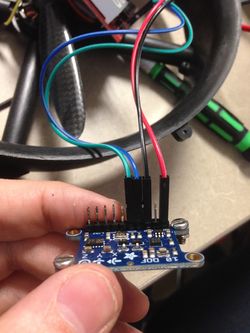
The IMU (Intertial Measurement Unit) is a sensor that measures the orientation of the quadcopter. IMU's are important because they provide the necessary information needed to control the quadcopter. Included in the IU is an accelerometer, a gyroscope, and a magnetometer. This is the device that is used in conjunction with the SJSUOne board to compute proper PID values and for the remote control to request angles for pitch, roll, and yaw. In our case, Y points to the north by default. The SJSUOne board reads these values and adjusts the quadcopter accordingly.
SJOne Flight Controller
The SJOne board is programmed and configured to be the flight controller of the quadcopter. The RC receiver, the sensor, and the ESC are all hooked up to the board. Each of these devices are actively working together and are controlled by the board. The receiver takes input from the RC and outputs it into the SJOne board. The board will process the requested PWM and will use this information to control the ESC. It will also process the requested angle of pitch and roll. The sensor readings will be used to process both the requested angle from the RC, and to process the flight stabilization calculations. This microcontroller controls every aspect required for the quadcopter to fly. Every action must first go through the SJOne board. FreeRTOS is extensively used on the board. Many critical actions such as remote control and flight stabilization are set up as tasks. The board will determine the priority given to each task.
Hardware Interface
Communication protocols used :
- UART - Serial communication and telemetry.
- PPM (Pulse Position Modulation) - Sequence of 6 channels of remote control transmitter signals into receiver on the quadcopter.
- Interrupts - Usage of the GPIO ports on the SJSU One board and the timer API to capture the PPM signals from the remote control transmitter to receiver.
- PWM (Pulse Width Modulation) - Decoding remote control signals into pulse signals the ESC's can use to drive the motors
Software Design
Our software utilizes object oriented programming (OOP) concepts. There are many types of "objects" which hold data in our system. For example, mFlightControllerAngles holds the current setpoint angles for all axis, mCurrentAngles holds the current x, y, and z-axis angles, and mMotorValues holds the motor values which will be applied to the motors. There are several different classes which separate the different functions in the system. The lowest level class, MotorControllerIface is an abstract class which contains undefined virtual methods. These virtual methods are defined in inherited classes which will use them. The FlightStabilizer class is responsible for controlling flight parameters using the sensor data and controlling lower-level flight logic. The highest level class, QuadcopterBase, is defined for high-level flight logic such as autonomous GPS flying.
PID Controller
PID (proportional, integral, and derivative) is a closed-loop control system that tries to get results closer to the desired setpoint by adjusting the inputs of the system. The PID controller calculates an error, which is the difference between the measured variable and desired setpoint. The PID controller tries to minimizes the error throughout the operation. Our system takes the measured sensor data and compares against expected values (from the remote control) to alter the PWM output which will be applied to the ESC's and motors. The PID controller contains 3 separate parameters - proportional, integral, and derivative. P depends on the present, I on the accumulation of past errors, and D is a prediction of future errors based on the current rate of change. A higher P tries harder to stabilize itself - which can result in overshoot if too high. I attempts to reduce error based on past errors. The longer the error persists, then the more I will attempt to correct itself. Too much I can result in oscillations at lower frequencies. D attempts to dampen the system and prevent fast movements. However, too high of a D will also introduce oscillations.
Implementation
System Initialization
- Get the sensor inputs
- Update the flight sensor system data
- Update flying logic
- Run PID loop
- If timing is skewed, light up LED and increment TimingSkewedCount.
- If armed, apply motor values. Otherwise, apply value 0 to motors.
Remote Control Signal Decoding
- Initialize ports for interrupt on rising and falling edges of inputs.
- On rising edge of signal, start timer capture.
- On falling edge of signal, stop timer capture.
- Pulse width = stop - start
Get normalized values of decoded remote control pulse width signals
- If throttle, scale from 0 to +100 for 0% to 100% by using a scaling factor and subtracting factor. Apply value to throttle of flight parameters.
- Else, scale from -45 degrees to +45 degrees by using a separate scaling factor and subtracting factor. Apply values for requested flight angles.
- Set limits and noise margins for robustness.
Integration
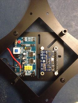
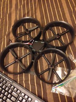
Below are pictures of the actual design and integration of the entire system.
Testing & Technical Challenges
PID Tuning Testing Methods
There are several ways to tune for PID. We have found Oscar Liang's blog on multicopters to be very helpful. http://blog.oscarliang.net/.
Brute Force
Before trying the Ziegler-Nichols or Cohen-Coon methods, we tried different brute force methods of tuning. First P, I, and D are set to 0. P is then gradually increased until there is a stable oscillation. I is then slowly increased until the quadcopter can quickly stabilize itself. After P and I are tuned, D can be tuned as well, however, D values may have an effect on P and I. After D is tuned, P and I may need to be retuned again. The brute force method is very straight forward, but it is very time consuming, and good results take a lot of time to acquire.
Cohen-Coon
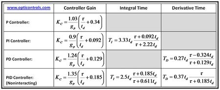
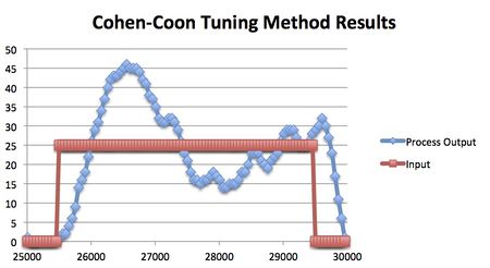
The Cohen-Coon method of tuning corrects the slow, steady-state response. This method is an offline method of tuning, meaning that a step change is introduced to the system once it is at steady state. The output is then measured based on the time constant and the time delay. The response can be used to evaluate the initial control parameters. Shown in the first picture, the delay time is td and tau is the time constant to reach 63% of the process input.
Ziegler-Nichols
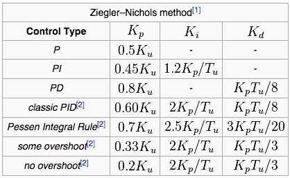
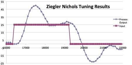
The Ziegler-Nichols tuning method was developed in the 1940's to obtain control parameters. The closed-loop tuning method, which we chose to use, involves finding the ultimate gain value, Ku, and the ultimate period of oscillation, Pu, to calculate Kc. It is a simple method of tuning PID controllers and can be refined and tuned further for better system response. The ultimate gain value, Ku, is found by finding the value of the proportional-only gain that causes the control loop to oscillate indefinitely at steady state. The parameters I and D are set to 0. The ultimate period, Pu, is the time required to complete one full oscillation while the system is at steady state. These two parameters alone are used to find the gain coefficients P, I, and D. An important thing to note here is the fact that these are only to be considered for initial values for further testing and fine tuning. Notice that there is still overshoot and an underdamped system response is given. It is important for the quadcopter to behave as a critically damped system.
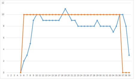
Stable PID Output
Upon completion of a stable quadcopter the graph produced below dictates a stable response in the PID control system. The random spikes most likely occurred from ground wind turbulences or the fact that we had a torn propeller.
Issues Faced
Issue #1
Issue: We first had inconsistent motor/propeller spinning. They were not spinning with normal behavior so we traced it back to the values that are applied to the motor from the remote control signals. The values decoded from the remote controls signals were incorrect. The ESC"s accept PWM servo pulses upon calibration and we initially had the SJSU One board outputting PWM duty cycle signals to the ESC. We reworked the remote control decoding functions to correct PWM pulses ranging from 1ms to 2ms wide pulses.
Result: The result was smooth operation of motors/propellers when throttle was applied from the remote control to the SJSU One board.
Issue #2
Issue: During the week of 4/24/15 to 4/29/15, we had remote control transmitter issues. It started out with random spikes in throttle pulse widths. We fixed the random spikes by adding control in our software, but eventually the throttle had no response. Change in the joystick would have no effect on the actual pulse width received from the receiver.
Result: Our solution was to order a different brand, especially not the Turnigy 9x. We opted for the FlySky FS-T6 remote control transmitter. So far, it has better response, light up display, and ability to adjust throttle curve which the Turnigy didn't have. Another issue that we have faced though, is the channel that we want our roll to be on does no work, instead, we have replaced the yaw channel with roll as a temporary fix.
Issue #3
Issue: After spending many hours, we were able to get the quadcopter to stabilize on both pitch and roll individually. However, when trying to fly, it tends to lean too far to one side. One fix is to manually input pitch or roll depending on the direction of the flight. This is not a good fix though, as it is still unstable.
Result: We believe that this error is a trimming error as opposed to a PID error. The quadcopter does not oscillate uncontrollably, rather, it just leans to one side too much.
Conclusion
We have learned many valuable things from this project. Besides team-work and process planning, we learned many things that can be applied to future work. Before this project, we had no experience with remote control PWM signal processing, PID feedback control, or flying with devices. This project has expanded our tool-set because we broadened our experience with real-world applications. Also, we learned that PID tuning is not just a simple plug and play process. Majority of the time spent on the project was devoted towards PID tuning. You can have a set of PID coefficient gains that are optimal for a smooth or aggressive flight and you won't know how it actually reacts until you start flying it. For example, we made a test-bed rig for tuning on 1 axis at a time and were able to log many different sets of PID values that seemed suitable for flying. Actually flying it on its own is a completely different story. Three different axis running plus outside disturbances such as wind and turbulence will have an affect on the real-time operation and flying. Another important thing we learned from this project is signal processing. We learned how to encode and decode signals from one form to another. What we have ultimately learned from this project is that planning and testing phases are crucial for a project, especially a quadcopter, to run well. Without a doubt, we will continue to utilize knowledge from this project towards other future projects.
Project Video
Most Stable Outdoor Flying : https://www.youtube.com/watch?v=JQmJV1W8POk
Hand Gesture Detection (Senior Project Add-on) : https://www.youtube.com/watch?v=w8gsY9lP0CI&feature=youtu.be
First Outdoor Test-run on a windy day https://www.youtube.com/watch?v=ufwh9sUGdOk
Second Outdoor Test-run on the same windy day https://www.youtube.com/watch?v=on9adUZsdkk
Initial testing of P values : https://www.youtube.com/watch?v=IqSVVo5YJBs&feature=youtu.be
Second stage of testing with P, I, and D values : https://www.youtube.com/watch?v=PpRCZm-XeGI
Initial flight testing : https://www.youtube.com/watch?v=7N-rQDqYn_8
Project Source Code
References
Acknowledgement
Any acknowledgement that you may wish to provide can be included here.
References Used
http://www.rctoys.com/pr/2009/05/25/all-about-brushless-motors-what-you-need-to-know/
http://blog.oscarliang.net/quadcopter-pid-explained-tuning/
http://blog.opticontrols.com/archives/383
http://robotics.stackexchange.com/questions/167/what-are-good-strategies-for-tuning-pid-loops
