Difference between revisions of "S15: SJeight Octocopter"
Proj user22 (talk | contribs) (→Abstract) |
Proj user22 (talk | contribs) (→Design & Implementation) |
||
| (102 intermediate revisions by 2 users not shown) | |||
| Line 1: | Line 1: | ||
| − | |||
| − | |||
| − | |||
| − | |||
| − | |||
| − | |||
| − | |||
| − | |||
| − | |||
| − | |||
| − | |||
| − | |||
== Project Title == | == Project Title == | ||
SJeight Octocopter | SJeight Octocopter | ||
== Abstract == | == Abstract == | ||
| − | The purpose of the project is to create a large custom built octocopter. It will rely on AHRS (Attitude and Heading Reference System) to stabilize the copter. The advantage for using eight motors is reliability, since the copter can still operate with one motor disabled. Another advantage is the ability to carry a larger payload than quadcopters. | + | The purpose of the project is to create a large custom built octocopter. It will rely on AHRS (Attitude and Heading Reference System) to stabilize the copter. The advantage for using eight motors is reliability, since the copter can still operate with one or more motor disabled. Another advantage is the ability to carry a larger payload than quadcopters. |
There are many design challenges for this project. The first being structural support. To help this along, a professional grade laser cutter and 3D printers were used to create the frame. Power consumption, weight, thrust, and sensors were carefully considered for this project. | There are many design challenges for this project. The first being structural support. To help this along, a professional grade laser cutter and 3D printers were used to create the frame. Power consumption, weight, thrust, and sensors were carefully considered for this project. | ||
== Objectives & Introduction == | == Objectives & Introduction == | ||
| − | + | The goal of this project was to design an octocopter that flies. This project consisted of four people and each team member worked in pairs. We used the SJone board for this project and implemented topics we learned in class. The class topics we used for this project are I2C, UART, Semaphores, and Queue. | |
=== Team Members & Responsibilities === | === Team Members & Responsibilities === | ||
| Line 36: | Line 24: | ||
|- | |- | ||
|I2C PWM Expander | |I2C PWM Expander | ||
| − | | | + | |I2C PWM EXpander |
| + | |I2C PWM Expander | ||
|I2C PWM Expander | |I2C PWM Expander | ||
| − | |||
|- | |- | ||
|CAD Design | |CAD Design | ||
| Line 45: | Line 33: | ||
|CAD Design | |CAD Design | ||
|- | |- | ||
| + | |GPS | ||
| + | |GPS | ||
| + | |GPS | ||
| + | |GPS | ||
| + | |- | ||
| + | |PID Algorithm | ||
| + | |PID Tuning | ||
| + | |PID Tuning | ||
| + | |PID Tuning | ||
| + | |- | ||
| + | |AHRS (Attitude Heading Reference System) | ||
| + | | | ||
| + | |XBEE Integration | ||
| | | | ||
| + | |- | ||
| + | |Nordic Integration | ||
| | | | ||
| − | | | + | |Arduino Remote |
| | | | ||
| + | |- | ||
|} | |} | ||
| Line 60: | Line 64: | ||
|- | |- | ||
| 1 | | 1 | ||
| + | | 3/29/15 | ||
| + | | Compile Parts List | ||
| + | | Complete | ||
| + | |- | ||
| + | | 2 | ||
| + | | 4/5/15 | ||
| + | | Source Parts | ||
| + | | Complete | ||
| + | |- | ||
| + | | 3 | ||
| 4/12/15 | | 4/12/15 | ||
| Interface with PWM expander | | Interface with PWM expander | ||
| − | | | + | | Complete |
|- | |- | ||
| − | | | + | | 4 |
| 4/19/15 | | 4/19/15 | ||
| Interface and Calibrate the AHRS with the SJone Board | | Interface and Calibrate the AHRS with the SJone Board | ||
| − | | | + | | Complete |
|- | |- | ||
| 3 | | 3 | ||
| 4/26/15 | | 4/26/15 | ||
| Add PID to SJone board | | Add PID to SJone board | ||
| − | | | + | | Complete |
|- | |- | ||
| − | | | + | | 5 |
| 5/3/15 | | 5/3/15 | ||
| Tune PID and Interface with RC Transmitter | | Tune PID and Interface with RC Transmitter | ||
| − | | | + | | PID not tuned |
|- | |- | ||
| − | | | + | | 6 |
| 5/10/15 | | 5/10/15 | ||
| Test Flight and fine Tuning | | Test Flight and fine Tuning | ||
| + | | Broken Props / Burned ESC | ||
| + | |- | ||
| + | | 7 | ||
| + | | 5/17/15 | ||
| + | | Remote / GPS / Nordic | ||
| + | | Complete (Nordic function removed - unreliable) | ||
| + | |- | ||
| + | | 8 | ||
| + | | 5/21/15 | ||
| + | | Fix Props and replace ESC | ||
| + | | Complete | ||
| + | |- | ||
| + | | 9 | ||
| + | | 5/23/15 | ||
| + | | Test Flight & Tune PID | ||
| | | | ||
|} | |} | ||
| Line 112: | Line 141: | ||
| $192 | | $192 | ||
|- | |- | ||
| − | | Carbon Fiber Propeller | + | | Carbon Fiber Propeller (Always have spares) |
| − | | | + | | 16 |
| $65 | | $65 | ||
| − | |- | + | |- |
| − | | Nuts and Bolts | + | | Nuts and Bolts (M4 Standard) |
| 200 | | 200 | ||
| $100 | | $100 | ||
| Line 135: | Line 164: | ||
| 1 | | 1 | ||
| $30 | | $30 | ||
| + | |- | ||
| + | | Xbee PRO | ||
| + | | 2 | ||
| + | | $60 | ||
| + | |- | ||
| + | | Arduino Mega | ||
| + | | 1 | ||
| + | | $30 | ||
| + | |- | ||
| + | | IMU | ||
| + | | 1 | ||
| + | | $75 | ||
| + | |- | ||
| + | | PWM Expander | ||
| + | | 1 | ||
| + | | $20 | ||
|} | |} | ||
| Line 141: | Line 186: | ||
=== Hardware Design === | === Hardware Design === | ||
| − | |||
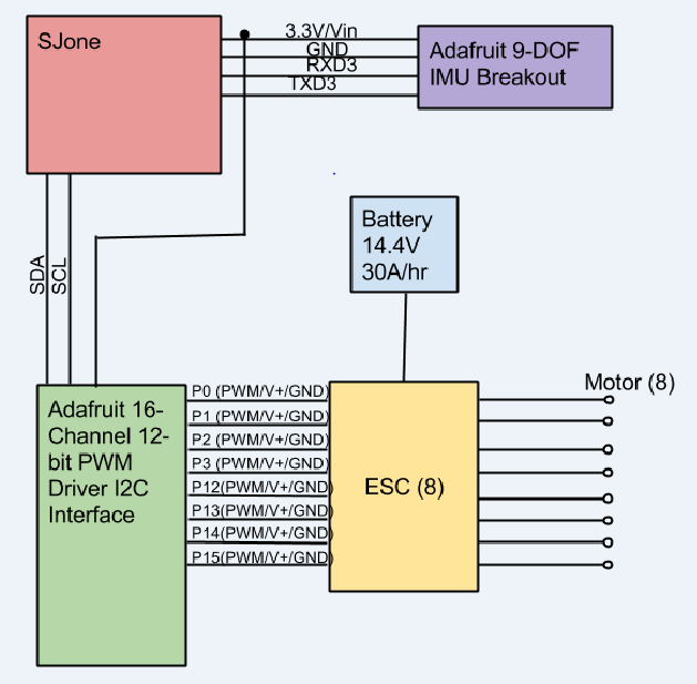
| − | ''' | + | [[File:S15 244 Hardware Circuit.png | 800px| thumb| center| Hardware Circuit Diagram]] |
| + | |||
| + | We initially decided on 10" blades, but soon realized that the longer the blade the more efficient the system. We went with 12" blades. We also realized that in order for the copter to fly we needed to find efficient batteries. The power density had to be extremely high, which is why we switched from the fifteen 2200 mAh batteries to the three 10 Ah batteries. | ||
| + | |||
| + | The hardware design was assembled by the whole team. This project was approached by drawing the architecture on SolidWorks. Figure 'CAD Drawing', illustrates the design of our SJeight. | ||
| + | |||
| + | '''Main Frame''' | ||
| + | |||
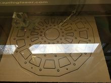
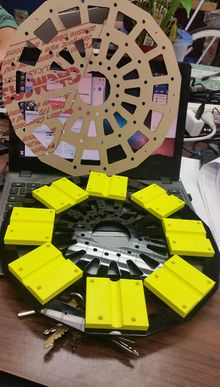
| + | The main frame of the octocopter was laser cut in the Mechanical Engineering Department Mechatronics Lab. A view of the laser cut is seen in Figure 'Laser Cutter'. Acrylic Plastic was recommended for the frame because it’s durable and low cost. The main frame had 3D printed rod slots which were sandwiched between two identical acrylic cuts. Figure '3D Printed Parts' and Figure 'Assembling the Frame' demonstrate the sandwiched carbon fiber rod. | ||
| + | |||
| + | '''Main Frame''' | ||
{| class="wikitable" | {| class="wikitable" | ||
|- | |- | ||
| − | + | | [[File:S15 244 Laser Cut Frame.JPG | 220px| thumb|center| Laser Cutter]] | |
| − | | [[File:S15 244 | + | | [[File:S15 244 SJeight Octocopter Frame 3D.jpg | 220px| thumb|center|3D Printed Parts and Frame]] |
| − | | [[File:S15 244 SJeight Octocopter | + | | [[File:S15 244 SJeight Octocopter Batt Frame.jpg | 220px| thumb|center|Battery Size Check]] |
| − | | [[File:S15 244 SJeight Octocopter | ||
|} | |} | ||
| − | ''' | + | '''Power Hub''' |
| + | |||
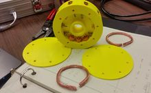
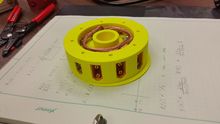
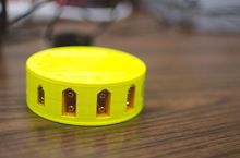
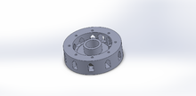
| + | The Power Hub shown in Figure Fully Assembled Power Hub, is designed to distribute power across all eight motors evenly. This was first design on SolidWorks and then 3D printed which is shown in Figure 'CAD of Power Hub'. Eight female XT-60 slots and three female XT-90 slots were soldered on a circular 6 gauge wire ring to distribute the power evenly. The 6AWG wire was a requirement because the motors in total pull 120 Amps through the power hub. The lower the wire gauge, the thicker the wire. As wire increases in thickness the resistance is reduced which lowers the power loss across the wire. Power loss is heat, so if there is any resistance in the hub, the hub would heat up to extreme temperatures. | ||
| + | |||
| + | '''Power Hub''' | ||
{| class="wikitable" | {| class="wikitable" | ||
|- | |- | ||
| − | | [[File:S15 244 SJeight Octocopter | + | | [[File:S15 244 SJeight Octocopter power hub.jpg| 220px| thumb|center| Unembarrassed ]] |
| − | | [[File:S15 244 SJeight Octocopter | + | | [[File:S15 244 SJeight Octocopter power hub test.jpg | 220px| thumb|center| Test Fit]] |
| − | | [[File:S15 244 SJeight Octocopter | + | | [[File:S15 244 SJeight Octocopter power hub assembled.jpg | 220px| thumb|center| Fully Assembled]] |
| − | | [[File:S15 244 SJeight Octocopter | + | | [[File:S15 244 SJeight Octocopter power hub cad.png | 220px| thumb|center | CAD of Power Hub]] |
|} | |} | ||
| − | ''' | + | '''Electronic Speed Controller''' |
| + | |||
| + | We mounted eight 80A ESC (Electronic Speed Controller) underneath the frame using zip ties. The input of the ESC was connected to the Power Hub where power is drawn. Shown in Figure ESC attrached to frame illustrates how the ESC are connected around the frame. The ESCs are connected to the DC motor, through the inside of the carbon fiber rod. The ESCs varies the throttle of the DC motors by sending PWM signals. The ESCs have three thick wires that go to three wires on the motor. They are labeled A, B, and C. The motor wires are color coded with red, yellow, and black wires. You will need to hook up the wires in a configuration you choose. We chose the following pairing. | ||
| + | |||
| + | {| class="wikitable" | ||
| + | |- | ||
| + | | Red | ||
| + | | A | ||
| + | |- | ||
| + | | Yellow | ||
| + | | B | ||
| + | |- | ||
| + | | Black | ||
| + | | C | ||
| + | |- | ||
| + | |} | ||
| + | |||
| + | In order to alternate the direction you switch any two wires. We chose the following pairing on every other ESC. | ||
| + | |||
{| class="wikitable" | {| class="wikitable" | ||
|- | |- | ||
| − | | | + | | Red |
| − | | | + | | B |
| − | | | + | |- |
| + | | Yellow | ||
| + | | A | ||
| + | |- | ||
| + | | Black | ||
| + | | C | ||
| + | |- | ||
|} | |} | ||
| − | '''Main | + | |
| + | [[File:S15 244 SJeight Octocopter power hub esc.jpg| 220px| thumb|center| ESC attached to frame]] | ||
| + | |||
| + | '''Brushless Motor''' | ||
| + | |||
| + | The brushless motor is mounted to the end of the rod. The brushless motors operates linearly which means when the motor shuts down, it slowly decreases rather than immediately braking. The brushless motor used for this design is the Donkey ST4010-820kv. The kv is the constant motor which indicates the maximum RPM the motor could rotate. The kV rating is how many rotations, without resistance, the motor will rotate per volt. A motor with a lower ESC usually has more torque and is a better choice for a multi-rotor craft. Our research showed that the optimal range for a multi-rotor is 300-800kV. Usually high kV motors are used for traditional airplanes. We chose the Donkey ST4010 due to the low price, despite it not being the best selection. | ||
| + | |||
| + | [[File:S15 244 SJeight Octocopter Motor Weight.jpg | 220px| thumb|center| Motor Weight]] | ||
| + | |||
| + | '''Battery''' | ||
| + | |||
| + | The original battery pack is displayed in the Figure 'Battery Size Check'. The high number of batteries is required due to the batteries 'C Rating'. The C rating is how to calculate how many Amps the battery can discharge at a single moment. The discharge rate is calculated by the below equation: | ||
| + | |||
| + | peak discharge = (capacity in Ah)*(C Rating) | ||
| + | |||
| + | We measured each motor to draw approximately 30A at idle and 60A at peak. This means that the design needed to accommodate 480 Amps at a single moment. Our final battery selection was three batteries each having a 30C rating and 10Ah capacity. This means that our discharge capability was 300A per battery, or 900A total. | ||
| + | |||
| + | ''' Power Supply Circuit to 'OR' the Batteries''' | ||
| + | |||
| + | Three packs were necessary to power the copter. Unfortunately, LiPo batteries cannot be connected | ||
| + | in parallel if the voltages are not closely matched. One solution is to use diode to prevent the batteries from | ||
| + | back-charging one another. Luckily, there are circuits available to create diodes from transistors. One option | ||
| + | was the LTC4352. | ||
| + | |||
| + | [[File:S15 244 SJeight Octocopter Batt Main.jpg | 220px| thumb | center| Main Batteries]] | ||
| + | |||
| + | '''Flight Controller''' | ||
| + | |||
| + | The flight controller is programmed using an Arduino Mega. The controller controls the coordinates and torque of our octocopter. Shown in Figure Flight Controller, illustrates the flight controller. The controller is designed on a PCB with two joysticks. The joysticks controls the coordinates and throttle of the copter. | ||
| + | |||
| + | ''' Controllers ''' | ||
| + | |||
{| class="wikitable" | {| class="wikitable" | ||
|- | |- | ||
| − | | [[File:S15 244 | + | | [[File: S15 244 SJeight Octocopter arduino controller.JPG| 220px| thumb | center | Arduino Mega Controller]] |
| − | | [[File:S15 244 SJeight Octocopter | + | | [[File: S15 244 SJeight Octocopter spectrum controller.PNG | 220px| thumb | center | Spektrum Dx6i]] |
| − | | | ||
|} | |} | ||
| − | ''' | + | '''CAD Design''' |
{| class="wikitable" | {| class="wikitable" | ||
|- | |- | ||
| − | | [[File:S15 244 SJeight Octocopter | + | | [[File:SJ8 Exploded.png | | 240px| thumb| center| Exploded CAD Drawing]] |
| − | | [[File:S15 244 SJeight Octocopter | + | | [[File:S15 244 SJeight Octocopter CAD Assemble.png| 220px| thumb| center| CAD Drawing]] |
| + | | [[File:S15 244 SJeight Octocopter CAD Leg.png|thumb| 220px |center| CAD of Leg]] | ||
|} | |} | ||
| − | ''' | + | '''Propeller Preparation''' |
{| class="wikitable" | {| class="wikitable" | ||
|- | |- | ||
| − | | [[File: S15 244 SJeight Octocopter | + | | [[File:S15 244 SJeight Octocopter Propeller.jpg| 220px |thumb| center| 12" Carbon Fiber Blade]] |
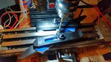
| − | | [[File:S15 244 SJeight Octocopter | + | | [[File:S15 244 SJeight Octocopter Prop Mill.jpg| 220px | thumb|center| Milling the Propeller Hole]] |
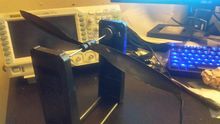
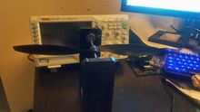
| − | | [[File:S15 244 SJeight Octocopter | + | | [[File:S15 244 SJeight Octocopter Unabal Prop.jpg| 220px|thumb| center| Unbalanced Propeller]] |
| − | | [[File:S15 244 SJeight Octocopter | + | | [[File:S15 244 SJeight Octocopter Prop Bal.jpg| 220px|thumb |center| Balanced Propeller]] |
|} | |} | ||
| − | |||
| − | + | '''SJboard and Interfaced Mount''' | |
| − | + | ||
| − | + | {| class="wikitable" | |
| − | + | |- | |
| + | | [[File: S15 244 SJeight Octocopter SJone Mount.PNG | 220px| thumb | center | SJone Mount]] | ||
| + | | [[File: S15 244 SJeight Octocopter SJone Mount on Frame.png | 220px| thumb | center | SJone Mount on Frame]] | ||
| + | |} | ||
| + | |||
| + | '''Assembly of Copter''' | ||
| + | {| class="wikitable" | ||
| + | |- | ||
| + | | [[File: S15 244 SJeight Octocopter Frame assemble.jpg | 220px| thumb|center| Assembling the Frame]] | ||
| + | | [[File:S15 244 SJeight Octocopter motor test.jpg| 220px| thumb | center| Motor Test]] | ||
| + | |} | ||
{| class="wikitable" | {| class="wikitable" | ||
|- | |- | ||
| − | | [[File: S15 244 SJeight Octocopter Battery circuit.PNG | thumb | center | 'OR' Circuit schematic]] | + | | [[File: S15 244 SJeight Octocopter Battery circuit.PNG | 220px| thumb | center | 'OR' Circuit schematic]] |
| − | | [[File: S15 244 SJeight Octocopter Ideal Diode.png | thumb | center | 'OR' Circuit]] | + | | [[File: S15 244 SJeight Octocopter Ideal Diode.png | 220px| thumb | center | 'OR' Circuit]] |
| + | | [[File: S15 244 SJeight Octocopter LTC4352.png| 220px| thumb | center | Circuit]] | ||
|} | |} | ||
=== Hardware Interface === | === Hardware Interface === | ||
| − | + | The SJeight interfaces with various peripherals. This includes the PCA9685 (16-channel, 12-bit PWM Fm+ I2C-bus LED controller) for PWM expansion, Razor IMU(Internal Measurement Unit) sparkfun, Adafruit Ultimate GPS Breakout Module, and 2.4GHz XBee module from Dig. | |
| + | |||
| + | To overcome the limited number of PWM I/O on the SJone board, extra hardware needed to be added to the project. The solution was the PCA9685. It provides 16 channels for PWM for the ESC(Electronic Speed Controller). This device communicates via I2C or Inner IC communication. The following figure shows a scope shot of the I2C bus. Even though the ESC is not directly controlled by the SJone, understanding of the signals are important. The ESC accepts a very specific signal. The frequency must be 50 Hz and ave a minimum pulse width of 0.7 milliseconds. The speed of the motor is then determined by the pulse width: 0.7 ms is 0% speed, 1.5 ms is 50% speed, and 2.3 ms is 100% speed. | ||
| + | |||
| + | |||
| + | '''PWM Analysis''' | ||
| + | {| class="wikitable" | ||
| + | |- | ||
| + | | [[File:S15 244 SJeight Octocopter I2C scope.png | 240px| thumb| left| I2C Bus]] | ||
| + | | [[File:S15 244 SJeight Octocopter MIN DC.png | 240px| thumb| right| PWM Minimum Pulse ]] | ||
| + | | [[File:S15 244 SJeight Octocopter PWM.jpeg | 240px| thumb| left| PWM Pulse and ESC Output]] | ||
| + | | [[File:S15 244 SJeight Octocopter MAX DC.png | 240px| thumb| right| PWM Maximum Pulse]] | ||
| + | |} | ||
=== Software Design === | === Software Design === | ||
| − | + | The main architecture implements FreeRTOS tasks to control the flow of reading sensors and calculations. A dedicated task is used to read the IMU. It holds the highest priority since stability is the most important aspect of the program. The second highest priority is processing the IMU data with the PID loop. The outout from the PID is sent to the motors. The controls are not as critical for operation and do not need to be updated as frequently. This puts the the reading remote task at a lower priority. After the data has been processed, it is sent to a buffer where the next controller offset will affect the system with a new IMU reading. Transmit and receive task we implemented using queue's. This allows the processing task to sleep and reduce waist in redundant loops. | |
| + | |||
| + | [[File:S15 244 SJeight Soft dia.jpeg | 480px| center| Main Program]] | ||
=== Implementation === | === Implementation === | ||
This section includes implementation, but again, not the details, just the high level. For example, you can list the steps it takes to communicate over a sensor, or the steps needed to write a page of memory onto SPI Flash. You can include sub-sections for each of your component implementation. | This section includes implementation, but again, not the details, just the high level. For example, you can list the steps it takes to communicate over a sensor, or the steps needed to write a page of memory onto SPI Flash. You can include sub-sections for each of your component implementation. | ||
| + | |||
| + | '''Razor IMU''' | ||
| + | |||
| + | We interfaced the Razor IMU using UART. The euler's angle is provided by the IMU. The datasheet is located at https://www.sparkfun.com/products/10736. | ||
| + | |||
| + | [[File:S15 244 SJeight Octocopter razor imu.PNG | 200px| thumb| center| Hardware Circuit Diagram]] | ||
| + | |||
| + | '''Wireless Communication''' | ||
| + | |||
| + | The SJone interfaces with the Xbee wireless module through UART2. The Xbee requests the latest joystick positions, and is feed into a queue by a producer task. The latest joystick positions are processed by a consumer task to analyze the readings and make decisions as to throttle, yaw, pitch, and role. | ||
| + | |||
| + | [[File:S15 244 SJeight Octocopter xbee.PNG | 240px| thumb| center| Hardware Circuit Diagram]] | ||
| + | |||
| + | '''Adafruit PWM Expander''' | ||
| + | |||
| + | Due to a need for 8 PWM sources, of which were not available on the Sjone, we used a PWM expander that was interfaced using I2C. After calculations are made for each motor speed, the Expander is written to update the PWMs to the eight ESCs and motors. This board is available at http://www.adafruit.com/products/1411. | ||
| + | |||
| + | [[File:S15 244 SJeight Octocopter pwm expand.PNG | 240px| thumb| center| Hardware Circuit Diagram]] | ||
| + | |||
| + | ''' DSMX Satellite Receiver ''' | ||
| + | |||
| + | The DSMX Satellite Receiver interfaces implements 115200 UART one stop bit and no parity. The packets were reversed engineered using the following website as reference: http://www.cgsy.com.au/archives/215 A buffer was needed to connect the DSMX receiver to the SJone board. Without this buffer, the signal was to weak to pull the line to ground. Another issue is keeping the packets aligned. A polling routing was necessary to keep alignment. | ||
| + | |||
| + | [[File:S15 244 SJeight Octocopter dsmx receiver.PNG | 240px| thumb| center| Hardware Circuit Diagram]] | ||
== Testing & Technical Challenges == | == Testing & Technical Challenges == | ||
| − | + | '''Receiver Reliability''' | |
| − | + | ||
| + | We basically packed the interpretations. We tested to see what happends if the power goes out from the receiver. When we lose communication with the receiver, we need to shut off power. | ||
| + | |||
| + | '''Motor Testing''' | ||
| + | |||
| + | Tested each motor individually and varied each motor at different throttles. Repeated the test with eight motors at the same time and isolated minor errors. The minor errors we faced was lack of solder connection from the motor to the ESC or the ESC to the battery. | ||
| + | |||
| + | '''IMU Calibration Testing''' | ||
| + | |||
| + | Planted the Adafruit 9-DOF IMU on the main frame and tested the Yaw, Pitch, and Roll. The data was collected and read through Hercules. We recommend using the 9-DOF rather than the 10-DOF because the 10-DOF lacks important open source. | ||
| − | + | '''PID Tuning''' | |
| − | === | + | A PID loop is extremely easy to implement. The concept is very basic, but the tuning is quite difficult. We highly recommend starting with a P system, adding the I term, then the D (if needed). PI systems are very common and can work just as well in many situations. |
| − | + | ||
| + | Tips: | ||
| + | 1) Make extremely small changes when modifying your gains. | ||
| + | 2) Create a PID loop for each axis. (Yaw, Pitch, Roll) | ||
| + | 3) Start with the P term on a single axis. It may not be perfectly stable. | ||
| + | 4) If it is not perfectly stable, get it the best you can then add the I term and repeat the process. | ||
| + | 5) If it is still not perfectly stable, but you believe it improving then get it to the best stability and add the D term. | ||
| + | |||
| + | When you have stability, I encourage you to add a disturbance to the system, such as quickly off setting the axis with a push or touch. The system should stabilize quickly. | ||
| + | |||
| + | Yaw is the most difficult to control and is done by creating a differential speed between the clockwise propellers and the counterclockwise propellers. This is why many people suggest that you place counter clockwise props on one axis, and clockwise props on the other axis. A better explanation is given here on wikipedia. [http://en.wikipedia.org/wiki/Quadcopter#Flight_control/ Wikipedia: Multirotor Flight Control] | ||
| + | |||
| + | '''Challenges and Problems''' | ||
| + | |||
| + | === Issue #1 === | ||
| + | |||
| + | One Issue that came up was the addressing of I2C. The datasheet for the PCA9685 presents the address as 0x40, but it is a 7-bit address. The SJeight function accepts a preshifted 8-bit address (0x80). This was discovered from probing the bus with an oscilloscope. | ||
| + | |||
| + | === Issue #2 === | ||
| + | Safety!!! One of our group member was injured with the copter. | ||
| + | |||
| + | === Issue #3 === | ||
| + | There was some unexpected behavior with the SJone vs. the Arduino, causing the ESC to full throttle and burn. Before attaching the propellers to the motor, test the motors RPM with an oscilloscope. This method allows us to analyze if the motor is responsive and running correctly. Once you re insure your code functions correctly, then attached the propellers back onto the motor. | ||
| + | |||
| + | === Issue #4 === | ||
| + | Tuning a PID controller is a control systems problem. This concept is taught in EE132. I highly encourage anyone who is considering building a multi-copter from scratch to research control systems. PID is not the best method for controlling a multi-copter, but is used due to it's simplicity. This isn't saying a lot for control systems. PID is hard. Tuning a PID can take hours or days depending on the complexity of your system. | ||
| + | |||
| + | === Issue #5 === | ||
| + | The extreme current involved in this project is very dangerous. A single short, 10 minutes before our demo, caused us to lose two of the ESCs. These ESCs are very expensive. We lost a total of three during the project. | ||
== Conclusion == | == Conclusion == | ||
| − | + | In the end this project gave us an amazing amount of experiences. We were required to delve into the disciplines of Mechanical, Mechatronics, Electrical, and Computer Engineers. | |
| + | |||
| + | The cost of this project was extremely high, and replacing parts continued to add to that cost throughout the project. It is highly recommended that you purchase at least 50% more parts than minimum. Highly volatile and sensitive parts such as the propellers and ESCs are a required to have replacements. | ||
| + | |||
| + | Although at this point in time our copter is not stable, we still have learned a great deal about the SJone board and interfacing many different components through UART, I2C, and SPI. We attempted to cover all of the protocols that we learned in CompE244 and may have been a little more ambitious than we should have been. | ||
| + | |||
| + | This project took a great deal of time, even with four engineers. | ||
=== Project Video === | === Project Video === | ||
| Line 232: | Line 435: | ||
=== Project Source Code === | === Project Source Code === | ||
* [https://sourceforge.net/projects/sjsu/files/CmpE_SJSU_S2015/ Sourceforge Source Code Link] | * [https://sourceforge.net/projects/sjsu/files/CmpE_SJSU_S2015/ Sourceforge Source Code Link] | ||
| + | * [https://github.com/csawtelle/SJEight-Octocopter.git/ Github Source Code Arduino/XBEE RC Version Link] | ||
| + | * [https://github.com/twin1q/SJeight-Octocopter.git/ Github Source Code DSXM Version Link] | ||
== References == | == References == | ||
=== Acknowledgement === | === Acknowledgement === | ||
| − | + | Thank you to Adafruit and Sparkfun for providing useful datasheets and demonstrations. Thank you to Sassoun Gostantian for helping us mill the PCB board for our Arduino Controller. And lastly a special thanks to Preet for giving the EE's the opportunity to take the class. | |
=== References Used === | === References Used === | ||
| − | + | 1. http://www.cgsy.com.au/archives/215 (DSMX Receiver) | |
| + | |||
| + | 2. http://brettbeauregard.com/blog/2011/04/improving-the-beginners-pid-introduction/ (PID Implementation) | ||
| + | |||
| + | 3. https://ghowen.me/build-your-own-quadcopter-autopilot/ (Building a Flight Controller) | ||
| + | |||
| + | 4. http://www.adafruit.com/ (PWM Expander) | ||
| − | + | 5. https://www.sparkfun.com/ (IMU) | |
| − | |||
Latest revision as of 17:12, 27 May 2015
Contents
Project Title
SJeight Octocopter
Abstract
The purpose of the project is to create a large custom built octocopter. It will rely on AHRS (Attitude and Heading Reference System) to stabilize the copter. The advantage for using eight motors is reliability, since the copter can still operate with one or more motor disabled. Another advantage is the ability to carry a larger payload than quadcopters. There are many design challenges for this project. The first being structural support. To help this along, a professional grade laser cutter and 3D printers were used to create the frame. Power consumption, weight, thrust, and sensors were carefully considered for this project.
Objectives & Introduction
The goal of this project was to design an octocopter that flies. This project consisted of four people and each team member worked in pairs. We used the SJone board for this project and implemented topics we learned in class. The class topics we used for this project are I2C, UART, Semaphores, and Queue.
Team Members & Responsibilities
| Christopher Sawtelle | Son Nguyen | Grant Welch | Noe Quintero |
|---|---|---|---|
| Component selection | Motor Mount | Power Hub | Frame |
| I2C PWM Expander | I2C PWM EXpander | I2C PWM Expander | I2C PWM Expander |
| CAD Design | CAD Design | CAD Design | CAD Design |
| GPS | GPS | GPS | GPS |
| PID Algorithm | PID Tuning | PID Tuning | PID Tuning |
| AHRS (Attitude Heading Reference System) | XBEE Integration | ||
| Nordic Integration | Arduino Remote |
Schedule
| Week# | Date | Task | Actual |
|---|---|---|---|
| 1 | 3/29/15 | Compile Parts List | Complete |
| 2 | 4/5/15 | Source Parts | Complete |
| 3 | 4/12/15 | Interface with PWM expander | Complete |
| 4 | 4/19/15 | Interface and Calibrate the AHRS with the SJone Board | Complete |
| 3 | 4/26/15 | Add PID to SJone board | Complete |
| 5 | 5/3/15 | Tune PID and Interface with RC Transmitter | PID not tuned |
| 6 | 5/10/15 | Test Flight and fine Tuning | Broken Props / Burned ESC |
| 7 | 5/17/15 | Remote / GPS / Nordic | Complete (Nordic function removed - unreliable) |
| 8 | 5/21/15 | Fix Props and replace ESC | Complete |
| 9 | 5/23/15 | Test Flight & Tune PID |
Parts List & Cost
| Name | Qty | Total Cost |
| Acrylic Sheet (Frame) | 1 | $30 |
| Lipo Battery | 3 | $220 |
| Carbon Fiber Rod | 8 | $120 |
| Motors | 8 | $120 |
| ESC | 8 | $192 |
| Carbon Fiber Propeller (Always have spares) | 16 | $65 |
| Nuts and Bolts (M4 Standard) | 200 | $100 |
| Battery Connectors | 11 | $30 |
| Zip Ties | 8 | $10 |
| ABS Plastic (3D Printer) | 1 | $25 |
| 6 AWG Wire | 1 | $30 |
| Xbee PRO | 2 | $60 |
| Arduino Mega | 1 | $30 |
| IMU | 1 | $75 |
| PWM Expander | 1 | $20 |
Design & Implementation
The design section can go over your hardware and software design. Organize this section using sub-sections that go over your design and implementation.
Hardware Design
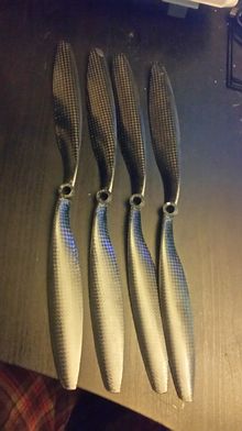
We initially decided on 10" blades, but soon realized that the longer the blade the more efficient the system. We went with 12" blades. We also realized that in order for the copter to fly we needed to find efficient batteries. The power density had to be extremely high, which is why we switched from the fifteen 2200 mAh batteries to the three 10 Ah batteries.
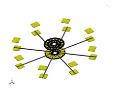
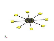
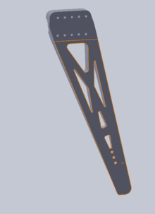
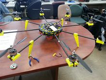
The hardware design was assembled by the whole team. This project was approached by drawing the architecture on SolidWorks. Figure 'CAD Drawing', illustrates the design of our SJeight.
Main Frame
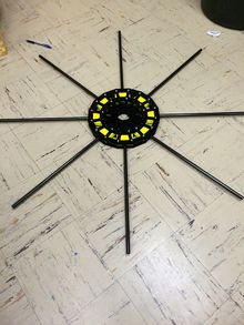
The main frame of the octocopter was laser cut in the Mechanical Engineering Department Mechatronics Lab. A view of the laser cut is seen in Figure 'Laser Cutter'. Acrylic Plastic was recommended for the frame because it’s durable and low cost. The main frame had 3D printed rod slots which were sandwiched between two identical acrylic cuts. Figure '3D Printed Parts' and Figure 'Assembling the Frame' demonstrate the sandwiched carbon fiber rod.
Main Frame
Power Hub
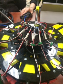
The Power Hub shown in Figure Fully Assembled Power Hub, is designed to distribute power across all eight motors evenly. This was first design on SolidWorks and then 3D printed which is shown in Figure 'CAD of Power Hub'. Eight female XT-60 slots and three female XT-90 slots were soldered on a circular 6 gauge wire ring to distribute the power evenly. The 6AWG wire was a requirement because the motors in total pull 120 Amps through the power hub. The lower the wire gauge, the thicker the wire. As wire increases in thickness the resistance is reduced which lowers the power loss across the wire. Power loss is heat, so if there is any resistance in the hub, the hub would heat up to extreme temperatures.
Power Hub
Electronic Speed Controller
We mounted eight 80A ESC (Electronic Speed Controller) underneath the frame using zip ties. The input of the ESC was connected to the Power Hub where power is drawn. Shown in Figure ESC attrached to frame illustrates how the ESC are connected around the frame. The ESCs are connected to the DC motor, through the inside of the carbon fiber rod. The ESCs varies the throttle of the DC motors by sending PWM signals. The ESCs have three thick wires that go to three wires on the motor. They are labeled A, B, and C. The motor wires are color coded with red, yellow, and black wires. You will need to hook up the wires in a configuration you choose. We chose the following pairing.
| Red | A |
| Yellow | B |
| Black | C |
In order to alternate the direction you switch any two wires. We chose the following pairing on every other ESC.
| Red | B |
| Yellow | A |
| Black | C |
Brushless Motor
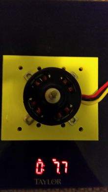
The brushless motor is mounted to the end of the rod. The brushless motors operates linearly which means when the motor shuts down, it slowly decreases rather than immediately braking. The brushless motor used for this design is the Donkey ST4010-820kv. The kv is the constant motor which indicates the maximum RPM the motor could rotate. The kV rating is how many rotations, without resistance, the motor will rotate per volt. A motor with a lower ESC usually has more torque and is a better choice for a multi-rotor craft. Our research showed that the optimal range for a multi-rotor is 300-800kV. Usually high kV motors are used for traditional airplanes. We chose the Donkey ST4010 due to the low price, despite it not being the best selection.
Battery
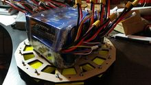
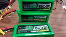
The original battery pack is displayed in the Figure 'Battery Size Check'. The high number of batteries is required due to the batteries 'C Rating'. The C rating is how to calculate how many Amps the battery can discharge at a single moment. The discharge rate is calculated by the below equation:
peak discharge = (capacity in Ah)*(C Rating)
We measured each motor to draw approximately 30A at idle and 60A at peak. This means that the design needed to accommodate 480 Amps at a single moment. Our final battery selection was three batteries each having a 30C rating and 10Ah capacity. This means that our discharge capability was 300A per battery, or 900A total.
Power Supply Circuit to 'OR' the Batteries
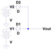
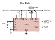
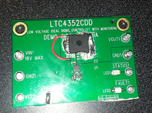
Three packs were necessary to power the copter. Unfortunately, LiPo batteries cannot be connected in parallel if the voltages are not closely matched. One solution is to use diode to prevent the batteries from back-charging one another. Luckily, there are circuits available to create diodes from transistors. One option was the LTC4352.
Flight Controller
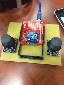
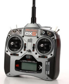
The flight controller is programmed using an Arduino Mega. The controller controls the coordinates and torque of our octocopter. Shown in Figure Flight Controller, illustrates the flight controller. The controller is designed on a PCB with two joysticks. The joysticks controls the coordinates and throttle of the copter.
Controllers
CAD Design
Propeller Preparation
SJboard and Interfaced Mount
Assembly of Copter
Hardware Interface
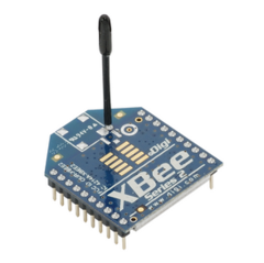
The SJeight interfaces with various peripherals. This includes the PCA9685 (16-channel, 12-bit PWM Fm+ I2C-bus LED controller) for PWM expansion, Razor IMU(Internal Measurement Unit) sparkfun, Adafruit Ultimate GPS Breakout Module, and 2.4GHz XBee module from Dig.
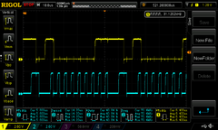
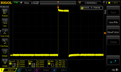
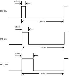
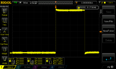
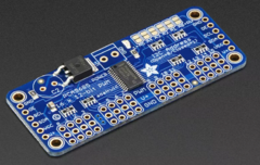
To overcome the limited number of PWM I/O on the SJone board, extra hardware needed to be added to the project. The solution was the PCA9685. It provides 16 channels for PWM for the ESC(Electronic Speed Controller). This device communicates via I2C or Inner IC communication. The following figure shows a scope shot of the I2C bus. Even though the ESC is not directly controlled by the SJone, understanding of the signals are important. The ESC accepts a very specific signal. The frequency must be 50 Hz and ave a minimum pulse width of 0.7 milliseconds. The speed of the motor is then determined by the pulse width: 0.7 ms is 0% speed, 1.5 ms is 50% speed, and 2.3 ms is 100% speed.
PWM Analysis
Software Design
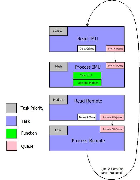
The main architecture implements FreeRTOS tasks to control the flow of reading sensors and calculations. A dedicated task is used to read the IMU. It holds the highest priority since stability is the most important aspect of the program. The second highest priority is processing the IMU data with the PID loop. The outout from the PID is sent to the motors. The controls are not as critical for operation and do not need to be updated as frequently. This puts the the reading remote task at a lower priority. After the data has been processed, it is sent to a buffer where the next controller offset will affect the system with a new IMU reading. Transmit and receive task we implemented using queue's. This allows the processing task to sleep and reduce waist in redundant loops.
Implementation
This section includes implementation, but again, not the details, just the high level. For example, you can list the steps it takes to communicate over a sensor, or the steps needed to write a page of memory onto SPI Flash. You can include sub-sections for each of your component implementation.
Razor IMU
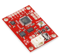
We interfaced the Razor IMU using UART. The euler's angle is provided by the IMU. The datasheet is located at https://www.sparkfun.com/products/10736.
Wireless Communication
The SJone interfaces with the Xbee wireless module through UART2. The Xbee requests the latest joystick positions, and is feed into a queue by a producer task. The latest joystick positions are processed by a consumer task to analyze the readings and make decisions as to throttle, yaw, pitch, and role.
Adafruit PWM Expander
Due to a need for 8 PWM sources, of which were not available on the Sjone, we used a PWM expander that was interfaced using I2C. After calculations are made for each motor speed, the Expander is written to update the PWMs to the eight ESCs and motors. This board is available at http://www.adafruit.com/products/1411.
DSMX Satellite Receiver
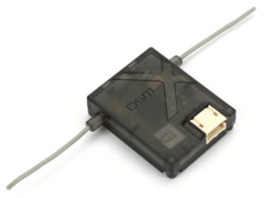
The DSMX Satellite Receiver interfaces implements 115200 UART one stop bit and no parity. The packets were reversed engineered using the following website as reference: http://www.cgsy.com.au/archives/215 A buffer was needed to connect the DSMX receiver to the SJone board. Without this buffer, the signal was to weak to pull the line to ground. Another issue is keeping the packets aligned. A polling routing was necessary to keep alignment.
Testing & Technical Challenges
Receiver Reliability
We basically packed the interpretations. We tested to see what happends if the power goes out from the receiver. When we lose communication with the receiver, we need to shut off power.
Motor Testing
Tested each motor individually and varied each motor at different throttles. Repeated the test with eight motors at the same time and isolated minor errors. The minor errors we faced was lack of solder connection from the motor to the ESC or the ESC to the battery.
IMU Calibration Testing
Planted the Adafruit 9-DOF IMU on the main frame and tested the Yaw, Pitch, and Roll. The data was collected and read through Hercules. We recommend using the 9-DOF rather than the 10-DOF because the 10-DOF lacks important open source.
PID Tuning
A PID loop is extremely easy to implement. The concept is very basic, but the tuning is quite difficult. We highly recommend starting with a P system, adding the I term, then the D (if needed). PI systems are very common and can work just as well in many situations.
Tips: 1) Make extremely small changes when modifying your gains. 2) Create a PID loop for each axis. (Yaw, Pitch, Roll) 3) Start with the P term on a single axis. It may not be perfectly stable. 4) If it is not perfectly stable, get it the best you can then add the I term and repeat the process. 5) If it is still not perfectly stable, but you believe it improving then get it to the best stability and add the D term.
When you have stability, I encourage you to add a disturbance to the system, such as quickly off setting the axis with a push or touch. The system should stabilize quickly.
Yaw is the most difficult to control and is done by creating a differential speed between the clockwise propellers and the counterclockwise propellers. This is why many people suggest that you place counter clockwise props on one axis, and clockwise props on the other axis. A better explanation is given here on wikipedia. Wikipedia: Multirotor Flight Control
Challenges and Problems
Issue #1
One Issue that came up was the addressing of I2C. The datasheet for the PCA9685 presents the address as 0x40, but it is a 7-bit address. The SJeight function accepts a preshifted 8-bit address (0x80). This was discovered from probing the bus with an oscilloscope.
Issue #2
Safety!!! One of our group member was injured with the copter.
Issue #3
There was some unexpected behavior with the SJone vs. the Arduino, causing the ESC to full throttle and burn. Before attaching the propellers to the motor, test the motors RPM with an oscilloscope. This method allows us to analyze if the motor is responsive and running correctly. Once you re insure your code functions correctly, then attached the propellers back onto the motor.
Issue #4
Tuning a PID controller is a control systems problem. This concept is taught in EE132. I highly encourage anyone who is considering building a multi-copter from scratch to research control systems. PID is not the best method for controlling a multi-copter, but is used due to it's simplicity. This isn't saying a lot for control systems. PID is hard. Tuning a PID can take hours or days depending on the complexity of your system.
Issue #5
The extreme current involved in this project is very dangerous. A single short, 10 minutes before our demo, caused us to lose two of the ESCs. These ESCs are very expensive. We lost a total of three during the project.
Conclusion
In the end this project gave us an amazing amount of experiences. We were required to delve into the disciplines of Mechanical, Mechatronics, Electrical, and Computer Engineers.
The cost of this project was extremely high, and replacing parts continued to add to that cost throughout the project. It is highly recommended that you purchase at least 50% more parts than minimum. Highly volatile and sensitive parts such as the propellers and ESCs are a required to have replacements.
Although at this point in time our copter is not stable, we still have learned a great deal about the SJone board and interfacing many different components through UART, I2C, and SPI. We attempted to cover all of the protocols that we learned in CompE244 and may have been a little more ambitious than we should have been.
This project took a great deal of time, even with four engineers.
Project Video
Upload a video of your project and post the link here.
Project Source Code
- Sourceforge Source Code Link
- Github Source Code Arduino/XBEE RC Version Link
- Github Source Code DSXM Version Link
References
Acknowledgement
Thank you to Adafruit and Sparkfun for providing useful datasheets and demonstrations. Thank you to Sassoun Gostantian for helping us mill the PCB board for our Arduino Controller. And lastly a special thanks to Preet for giving the EE's the opportunity to take the class.
References Used
1. http://www.cgsy.com.au/archives/215 (DSMX Receiver)
2. http://brettbeauregard.com/blog/2011/04/improving-the-beginners-pid-introduction/ (PID Implementation)
3. https://ghowen.me/build-your-own-quadcopter-autopilot/ (Building a Flight Controller)
4. http://www.adafruit.com/ (PWM Expander)
5. https://www.sparkfun.com/ (IMU)
