Difference between revisions of "S15: Bug Rider"
Proj user14 (talk | contribs) (→Parts List & Cost) |
Proj user14 (talk | contribs) (→Project Video) |
||
| (110 intermediate revisions by the same user not shown) | |||
| Line 1: | Line 1: | ||
| − | == Bug Rider == | + | == Bug Rider== |
== Abstract == | == Abstract == | ||
| − | + | ||
| + | The "'''Bug Rider'''" is robotic toy car which is ridden by the fish in the aquarium tank on top of the vehicle!!!! Confused ??? | ||
| + | |||
| + | Ok ,So the fish which is placed inside the fish tank placed on top of the car will be moving in random directions and its movement is captured by the camera attached to the supporting frame of the vehicle.The movements are image-processed and the data is given to the "SJ-ONE BOARD" which in turn sends the wireless signals to the "SJ-ONE BOARD" present on the car which finally drives the car in that particular direction as the Hex-Bug's direction. | ||
| + | |||
| + | Below is the sample pictorial representation of the project. | ||
| + | |||
== Objectives & Introduction == | == Objectives & Introduction == | ||
| − | + | We are designing a prototype version of Fish on Wheels using a Mobile Camera,RC Vehicle for holding the Fish Tank setup and Sjoneboard for controlling the vehicle.Using the contrast of the fish with the bottom of the fish tank, the position is determined and used to send commands to the Sjoneboard for moving the car into that direction. | |
| + | We use Image Processing in Python for determining the Position of the Fish. Nordiac Wirless is used for wireless communication between RC Vehicle and Laptop. Uart Serial Communication is used for sending commands from Python to Sjoneboard.PWM driver is used for controlling the RC Vehicle. | ||
=== Team Members & Responsibilities === | === Team Members & Responsibilities === | ||
* [Vishnuram Venkataswamy Sampathkumar]<br> | * [Vishnuram Venkataswamy Sampathkumar]<br> | ||
| − | ** < | + | ** <Image Processing Module> |
* [Krishna Sai Sevilimedu Veeravalli]<br> | * [Krishna Sai Sevilimedu Veeravalli]<br> | ||
| − | ** < | + | ** <Nordiac Wireless & Serial Communication> |
* [Saketh Ram Bhamidimarri]<br> | * [Saketh Ram Bhamidimarri]<br> | ||
| − | ** < | + | ** <Hardware Design and Integration> |
* [Prakash Kurup]<br> | * [Prakash Kurup]<br> | ||
| − | ** < | + | ** <PWM Driver and testing> |
== Schedule == | == Schedule == | ||
| − | + | ||
{| class="wikitable" | {| class="wikitable" | ||
| Line 55: | Line 62: | ||
|04/28/2015 | |04/28/2015 | ||
|Serial communication & Nordic wireless communication | |Serial communication & Nordic wireless communication | ||
| − | | align="center"| | + | | align="center"|*Completed* |
|- | |- | ||
|- | |- | ||
| Line 61: | Line 68: | ||
|05/29/2015 | |05/29/2015 | ||
|05/05/2015 | |05/05/2015 | ||
| − | |Platform design for the hexbug | + | |Platform design for the hexbug and building the framework to hold the camera on top |
| − | | align="center"| | + | | align="center"|*Completed* |
|- | |- | ||
|- | |- | ||
| Line 69: | Line 76: | ||
|05/12/2015 | |05/12/2015 | ||
|Ultrasonic sensor for obstacle avoidance | |Ultrasonic sensor for obstacle avoidance | ||
| − | | align="center"| | + | | align="center"|*Completed* |
|- | |- | ||
|- | |- | ||
| Line 76: | Line 83: | ||
|05/19/2015 | |05/19/2015 | ||
|Integration of complete system and testing | |Integration of complete system and testing | ||
| − | | align="center"| | + | | align="center"|*Completed* |
|- | |- | ||
|- | |- | ||
| Line 83: | Line 90: | ||
|05/26/2015 | |05/26/2015 | ||
|Final Testing and demo | |Final Testing and demo | ||
| − | | align="center"| | + | | align="center"|*Completed* |
|- | |- | ||
|} | |} | ||
| Line 98: | Line 105: | ||
| align="center"|1||1||RC Car||New Bright||Jeep 9.6V||align="right"|$60.00 | | align="center"|1||1||RC Car||New Bright||Jeep 9.6V||align="right"|$60.00 | ||
|- | |- | ||
| − | | align="center"|2|| | + | | align="center"|2||2||SJ-One Board||NXP LPC1758||SJSU development board, LPC1758||align="right"|$160.00 |
|- | |- | ||
| − | | align="center"|3|| | + | | align="center"|3||1||HexBug||Innovation First||HexBug Aquabot - Green color||align="right"|$8.96 |
|- | |- | ||
| − | | align="center"|4||1|| | + | | align="center"|4||1||Dual H-Bridge Motor Drive||Drok||L298N||align="right"|$8.48 |
| + | |- | ||
| + | | align="center"|5||1||Acrylic sheet||Tap-Plastics||Pure opaque-milky white||align="right"|$24.29 | ||
|- | |- | ||
| − | | align="center"| | + | | align="center"|6||3||Camera holding rods||Tap-Plastics||Plastic material||align="right"|$ 17.40 |
|- | |- | ||
| − | | align="center"|||||'''Total Cost'''||||||align="right"|''' | + | | align="center"|7||2||Antennas||University||10-feet range antennas||align="right"|$ 6.00 |
| + | |- | ||
| + | | align="center"|8||1||Double-sided tape||Tap-Plastics||Double sided tape for plastic material||align="right"|$ 5.06 | ||
| + | |- | ||
| + | | align="center"|9||3||Welding work and Integration of the framework||Tap-Plastics||Glass Fibre rods for the support frame||align="right"|$ 20.00 | ||
| + | |- | ||
| + | | align="center"|10||1||Ultrasonic Sensor||Parallax||Parallax Ping Ultrasonic Sensor||align="right"|$ 35.00 | ||
| + | |- | ||
| + | | align="center"|11||1||Hexbug Aquarium||Innovation First||Hexbug Aquabot 2.0 Harbour||align="right"|$ 35.00 | ||
| + | |- | ||
| + | | |||||'''Total Cost'''||||||align="right"|'''$370.19''' | ||
|- | |- | ||
|} | |} | ||
== Design & Implementation == | == Design & Implementation == | ||
| − | + | ||
=== Hardware Design === | === Hardware Design === | ||
| − | + | The main components required for this project are : | |
| + | |||
| + | (1) A Toy Car of dimensions approximately 25*12 inches which we bought from WALMART. | ||
| + | |||
| + | (2) An Acrylic sheet of dimensions 30*15 milky white color with highest opaqueness for light bought at TAP-PLASTICS. | ||
| + | |||
| + | (3) A framework consisting of vertical rods attached to the front and back of the car and a horizontal rod which can be movable on the vertical rods.The camera will be attached right at the middle of the horizontal rod. | ||
| + | The intention of the horizontal rod sliding on the vertical rods is to adjust the height of the camera position relative to the platform. | ||
| + | |||
| + | (4) Ultra-sonic sensors attached at the front portion of the car to provide the obstacle avoidance feature to the car. | ||
| + | |||
| + | (5) The "SJ-ONE" board will be placed underneath the platform,in the slot provided for the batteries of the car. | ||
| + | |||
| + | (6) 9V batteries for Powering "SJ-ONE" board and RC Car. | ||
| + | |||
| + | (7) L298H Motor Driver for Controlling RC Car | ||
| + | |||
| + | *Below is the equipment required for the project | ||
| + | |||
| + | [[File:S15_244_BUGRIDER1_part1.jpg]] [[File:S15_244_BUGRIDER1_part2.jpg]] | ||
| + | |||
| + | [[File:S15_244_BUGRIDER1_part3.jpg]] [[File:S15_244_BUGRIDER1_part4.jpg]] | ||
=== Hardware Interface === | === Hardware Interface === | ||
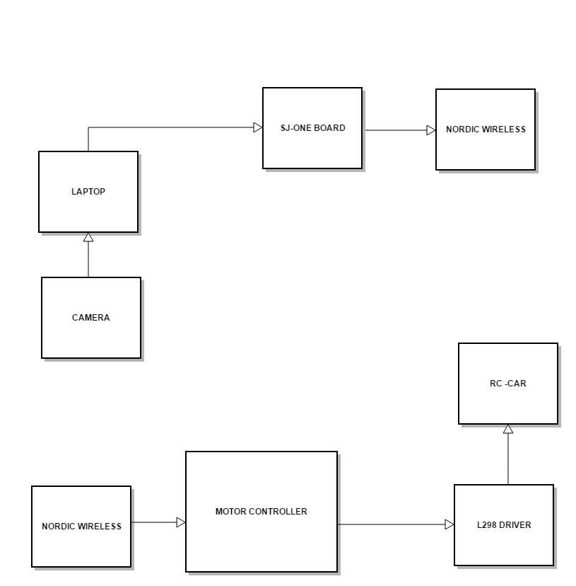
| − | + | * The "SJ-ONE BOARD" is used for the control of DC motor and SERVO motor control using Pulse Width Modulation(PWM). | |
| + | |||
| + | * The DC motor and the SERVO motors are connected to the "SJ-ONE BOARD" using jumper cables. | ||
| + | |||
| + | * An Antenna is attached to the "SJ-ONE BOARD" which is used for the communication with the other "SJ-ONE BOARD" connected to the laptop through Nordic Wireless Communication. | ||
| + | |||
| + | * The wireless Camera attached to the horizontal section of the framework will be capturing the movement of the Hex-Bug toy and transmitting the data to the laptop via bluetooth. | ||
| − | + | *The ultra-Sonic Sensors which are placed at the front portion of the vehicle for the obstacle-avoidance feature is connected to the "SJ-ONE BOARD" through jumper cables. | |
| − | |||
| − | === Implementation === | + | * Below is the block diagram of the project: |
| − | + | ||
| + | [[File:S15_244_BLOCKDIAGRAM_BUGRIDER.jpg]] | ||
| + | |||
| + | === Software Design and Implementation === | ||
| + | '''Image Processing''' | ||
| + | |||
| + | The Software Design is divided into two parts. The first part of the software is running in the PC end and the second part of the software is running at the SJ One Board. | ||
| + | The first part of the software running at the PC requires the Image Processing. | ||
| + | Image Processing: | ||
| + | |||
| + | Image processing is done by using OpenCV libraries in Python.We also use NumPy (Numerical Python) Package which is used by OpenCV for image processing. | ||
| + | |||
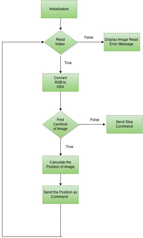
| + | We capture the Video frames in Python by using VideoCapture() function and convert RGB image to HSV (Hue-Saturation-Value), for extracting a colored object. In HSV, it is more easier to represent a color than RGB color-space. After converting the image to HSV color-space,image will be threshold for a range of desired object color. Position of the image is returned by using moments() function of OpenCV library. It gives centroid of the object in terms of (x,y) co-ordinates. By using the (x,y) co-ordinates, the position of the object is determined in the tracking window and send the SJone Board through Serial Communication. | ||
| + | |||
| + | pySerial package provides required libraries for serial communication in python. Desired port number is set and data is send using write() function. | ||
| + | |||
| + | Flow Chart - Image Processing | ||
| + | |||
| + | [[File:S15_244_BUGRIDER2.jpg]] | ||
| + | |||
| + | The second part of software will be running in SJone board: | ||
| + | |||
| + | We use one SJone board for transferring data from PC to another SJone board which is used in RC car for controlling the car. | ||
| + | |||
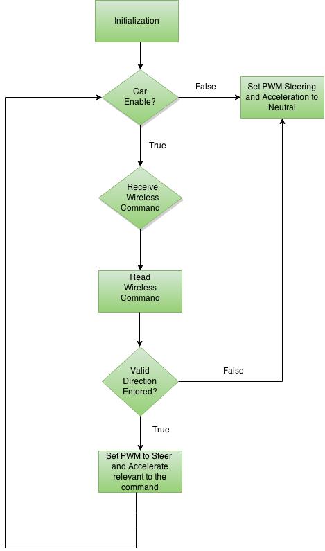
| + | The Software which is running in the SJone board which is used for transferring data through UART serial communication from PC contains a task,once the task begins executing, it waits for the serial data from the PC. On receiving the data from PC,it transfer the data to Nordic wireless function which sends the data to other SJone board. | ||
| + | |||
| + | Flow Chart - SJone board: | ||
| + | |||
| + | [[File:S15_244_BUGRIDER3.jpg]] | ||
| + | |||
| + | '''Motor Controller''' | ||
| + | |||
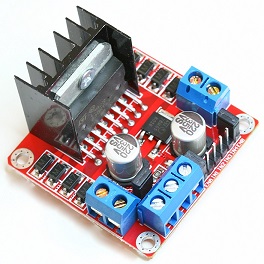
| + | The L298 dual H-Bridge Motor Controller is used to control the speed and direction of dc motor and servo motor respectively. Motor controller has one enable and two interrupt pins for each motor. | ||
| + | |||
| + | [[File:S15_244_L298.jpg]] | ||
| + | |||
| + | The motor controller is initialized by setting two PWM pins of SJone board to 1KHz frequency using the inbuilt functions provided Prof. Preetpal Kang (CMPE 244 instructor). Four GPIO pins are used as interrupt pins for both the dc motor and servo motor. Code snippet as follows: | ||
| + | |||
| + | [[File:S15_244_PWM1.jpg]] | ||
| + | |||
| + | |||
| + | We set the GPIO pins for acceleration and steering as output as follows: | ||
| + | |||
| + | [[File:S15_244_PWM2.jpg]] | ||
| + | |||
| + | |||
| + | Function to set the speed of the motor and the direction of the dc motor and servo motor is as follows: | ||
| + | |||
| + | [[File:S15_244_PWM3.jpg]] | ||
| + | |||
| + | |||
| + | '''Ultrasonic Sensor''' | ||
| + | |||
| + | For this project we used an ultrasonic sensor to find the distance for obstacle avoidance. | ||
| + | |||
| + | Initially we used Seeed Studio Ultrasonic Range Finder (SEN136B5B) which is similar to PING))) Ultrasonic Distance Sensor. The sensor has has 3 pins: Vcc, GND and SIG where SIG acts as input and output at the same time. | ||
| + | |||
| + | The sensor was initially working but due to erratic voltage supply to it, the sensor somehow got burned and stopped working. So we changed the sensor to LV Maxsonar EZ ultrasonic sensor. | ||
| + | |||
| + | [[File:S15_244_ULTRASONIC2.jpg]] | ||
| + | |||
| + | The ultrasonic sensor interfaces using an ADC interface. The SJone board is equipped with an analog-to-digital converter which converts an analog signal (continuous voltage that varies over time) into corresponding digital values (discrete integers that approximate the input voltage). The 12-bit ADC operates on 3.3V which means that a voltage range between 0V and 3.3V can be divided into 212 or 4096 discrete steps. The sensor has 7 pins from which 3 pins are used to connect to the board: | ||
| + | 1. Pin "+5" on sensor to Pin "3.3V" on SJone board. | ||
| + | 2. Pin "GND" on sensor to Pin "Gnd" on SJone board. | ||
| + | 3. Pin "AN" on sensor to Pin "A0-4" on SJone board. | ||
| + | |||
| + | The sensor values are read using adc0_get_reading_function. The ADC values are then converted to voltage values and the voltage values to centimeters to measure the distance. x | ||
| + | |||
| + | [[File:S15_244_ULTRASONIC3.jpg]] | ||
== Testing & Technical Challenges == | == Testing & Technical Challenges == | ||
| − | |||
| − | |||
| − | + | === My Issue #1 === | |
| + | We faced some issues which we would like to mention and how we overcame those. | ||
| + | |||
| + | '''Hardware items:''' After the idea was finalized and the how-to-do stuff was imagined and designed,the initial problem was to where to find the materials,the hardware tools which would exactly meet the requirements of the project. | ||
| + | After searching various hardware stores,we would a really nice place called the "TAP-PLASTICS" where the technician named Kevin was really helpful in his suggestions and the improvisations which can be used. | ||
| + | |||
| + | === My Issue #2 === | ||
| − | === My Issue # | + | '''Image Processing Module:''' It took some time for us to finalize the HSV platform for detecting the Fish.We initially tried converted the image to Grey Scale Platform,but we failed to track the image.Finding a Platform for Image Processing also took sometime,as we initially tried to use C++ for Image Processing Platform,but we failed to apply image processing algorithms which in future, we will work on it. |
| − | + | ||
| + | === My Issue #3 === | ||
| + | |||
| + | '''Ultrasonic Sensor:''' We faced issues with ultrasonic sensor.Initially it worked well but due to some issues it did not give accurate values.We replaced the sensor with an higher quality sensor.The updated sensor is working accurately and helps in providing obstacle avoidance for the car. | ||
== Conclusion == | == Conclusion == | ||
| − | + | ||
| + | The whole project experience was fun and very educational. At first we thought that Image Processing algorithms are available online, so just editing them will make our project work.But we learned a hard lesson that ,lot of our time would be saved if we write our own code instead of editing them.We learned to configure and use Nordic wireless module.We got to know how PWM Driver and Serial Communication works. | ||
| + | |||
| + | The project can be expanded by making it as an standlone project.We are learning to write a driver for interfacing the camera to the microprocessor,which soon we will be implementing in our project. | ||
=== Project Video === | === Project Video === | ||
| − | + | Below is the link for our project : | |
| + | |||
| + | https://www.youtube.com/watch?v=y4z0cLZsiMY | ||
=== Project Source Code === | === Project Source Code === | ||
| Line 145: | Line 270: | ||
== References == | == References == | ||
=== Acknowledgement === | === Acknowledgement === | ||
| − | + | We, the team of Bug-Rider would like to wholeheartedly thank our friend, our guide and our Professor '''Preetpal Kang''' for guiding us, encouraging us to do these projects and imparting knowledge and wisdom to us in our academics as well as for our career.Thank You Preet! | |
=== References Used === | === References Used === | ||
| − | + | (1) http://www.socialledge.com/sjsu/index.php?title=Main_Page | |
| + | |||
| + | (2) https://learn.adafruit.com/series/learn-arduino | ||
| + | |||
| + | (3) http://www.maxbotix.com/documents/LV-MaxSonar-EZ_Datasheet.pdf | ||
=== Appendix === | === Appendix === | ||
You can list the references you used. | You can list the references you used. | ||
Latest revision as of 19:20, 7 June 2015
Contents
Bug Rider
Abstract
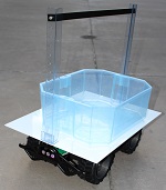
The "Bug Rider" is robotic toy car which is ridden by the fish in the aquarium tank on top of the vehicle!!!! Confused ???
Ok ,So the fish which is placed inside the fish tank placed on top of the car will be moving in random directions and its movement is captured by the camera attached to the supporting frame of the vehicle.The movements are image-processed and the data is given to the "SJ-ONE BOARD" which in turn sends the wireless signals to the "SJ-ONE BOARD" present on the car which finally drives the car in that particular direction as the Hex-Bug's direction.
Below is the sample pictorial representation of the project.
Objectives & Introduction
We are designing a prototype version of Fish on Wheels using a Mobile Camera,RC Vehicle for holding the Fish Tank setup and Sjoneboard for controlling the vehicle.Using the contrast of the fish with the bottom of the fish tank, the position is determined and used to send commands to the Sjoneboard for moving the car into that direction. We use Image Processing in Python for determining the Position of the Fish. Nordiac Wirless is used for wireless communication between RC Vehicle and Laptop. Uart Serial Communication is used for sending commands from Python to Sjoneboard.PWM driver is used for controlling the RC Vehicle.
Team Members & Responsibilities
- [Vishnuram Venkataswamy Sampathkumar]
- <Image Processing Module>
- [Krishna Sai Sevilimedu Veeravalli]
- <Nordiac Wireless & Serial Communication>
- [Saketh Ram Bhamidimarri]
- <Hardware Design and Integration>
- [Prakash Kurup]
- <PWM Driver and testing>
Schedule
| Sl. No | Start Date | End Date | Task | Status |
|---|---|---|---|---|
| 1 | 03/31/2015 | 04/07/2015 | Order required components | *Completed* |
| 2 | 04/08/2015 | 04/14/2015 | Image processing for object tracking | *Completed* |
| 3 | 04/15/2015 | 04/21/2015 | PWM driver and motor calibration | *Completed* |
| 4 | 04/22/2015 | 04/28/2015 | Serial communication & Nordic wireless communication | *Completed* |
| 5 | 05/29/2015 | 05/05/2015 | Platform design for the hexbug and building the framework to hold the camera on top | *Completed* |
| 6 | 05/06/2015 | 05/12/2015 | Ultrasonic sensor for obstacle avoidance | *Completed* |
| 7 | 05/13/2015 | 05/19/2015 | Integration of complete system and testing | *Completed* |
| 8 | 05/20/2015 | 05/26/2015 | Final Testing and demo | *Completed* |
Parts List & Cost
| Item# | Qty | Description | Manufacturer | Part Number | Total Cost |
|---|---|---|---|---|---|
| 1 | 1 | RC Car | New Bright | Jeep 9.6V | $60.00 |
| 2 | 2 | SJ-One Board | NXP LPC1758 | SJSU development board, LPC1758 | $160.00 |
| 3 | 1 | HexBug | Innovation First | HexBug Aquabot - Green color | $8.96 |
| 4 | 1 | Dual H-Bridge Motor Drive | Drok | L298N | $8.48 |
| 5 | 1 | Acrylic sheet | Tap-Plastics | Pure opaque-milky white | $24.29 |
| 6 | 3 | Camera holding rods | Tap-Plastics | Plastic material | $ 17.40 |
| 7 | 2 | Antennas | University | 10-feet range antennas | $ 6.00 |
| 8 | 1 | Double-sided tape | Tap-Plastics | Double sided tape for plastic material | $ 5.06 |
| 9 | 3 | Welding work and Integration of the framework | Tap-Plastics | Glass Fibre rods for the support frame | $ 20.00 |
| 10 | 1 | Ultrasonic Sensor | Parallax | Parallax Ping Ultrasonic Sensor | $ 35.00 |
| 11 | 1 | Hexbug Aquarium | Innovation First | Hexbug Aquabot 2.0 Harbour | $ 35.00 |
| Total Cost | $370.19 |
Design & Implementation
Hardware Design
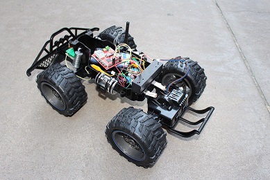
The main components required for this project are :
(1) A Toy Car of dimensions approximately 25*12 inches which we bought from WALMART.
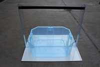
(2) An Acrylic sheet of dimensions 30*15 milky white color with highest opaqueness for light bought at TAP-PLASTICS.
(3) A framework consisting of vertical rods attached to the front and back of the car and a horizontal rod which can be movable on the vertical rods.The camera will be attached right at the middle of the horizontal rod. The intention of the horizontal rod sliding on the vertical rods is to adjust the height of the camera position relative to the platform.
(4) Ultra-sonic sensors attached at the front portion of the car to provide the obstacle avoidance feature to the car.
(5) The "SJ-ONE" board will be placed underneath the platform,in the slot provided for the batteries of the car.
(6) 9V batteries for Powering "SJ-ONE" board and RC Car.
(7) L298H Motor Driver for Controlling RC Car
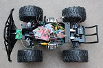
- Below is the equipment required for the project
Hardware Interface
- The "SJ-ONE BOARD" is used for the control of DC motor and SERVO motor control using Pulse Width Modulation(PWM).
- The DC motor and the SERVO motors are connected to the "SJ-ONE BOARD" using jumper cables.
- An Antenna is attached to the "SJ-ONE BOARD" which is used for the communication with the other "SJ-ONE BOARD" connected to the laptop through Nordic Wireless Communication.
- The wireless Camera attached to the horizontal section of the framework will be capturing the movement of the Hex-Bug toy and transmitting the data to the laptop via bluetooth.
- The ultra-Sonic Sensors which are placed at the front portion of the vehicle for the obstacle-avoidance feature is connected to the "SJ-ONE BOARD" through jumper cables.
- Below is the block diagram of the project:
Software Design and Implementation
Image Processing
The Software Design is divided into two parts. The first part of the software is running in the PC end and the second part of the software is running at the SJ One Board. The first part of the software running at the PC requires the Image Processing. Image Processing:
Image processing is done by using OpenCV libraries in Python.We also use NumPy (Numerical Python) Package which is used by OpenCV for image processing.
We capture the Video frames in Python by using VideoCapture() function and convert RGB image to HSV (Hue-Saturation-Value), for extracting a colored object. In HSV, it is more easier to represent a color than RGB color-space. After converting the image to HSV color-space,image will be threshold for a range of desired object color. Position of the image is returned by using moments() function of OpenCV library. It gives centroid of the object in terms of (x,y) co-ordinates. By using the (x,y) co-ordinates, the position of the object is determined in the tracking window and send the SJone Board through Serial Communication.
pySerial package provides required libraries for serial communication in python. Desired port number is set and data is send using write() function.
Flow Chart - Image Processing
The second part of software will be running in SJone board:
We use one SJone board for transferring data from PC to another SJone board which is used in RC car for controlling the car.
The Software which is running in the SJone board which is used for transferring data through UART serial communication from PC contains a task,once the task begins executing, it waits for the serial data from the PC. On receiving the data from PC,it transfer the data to Nordic wireless function which sends the data to other SJone board.
Flow Chart - SJone board:
Motor Controller
The L298 dual H-Bridge Motor Controller is used to control the speed and direction of dc motor and servo motor respectively. Motor controller has one enable and two interrupt pins for each motor.
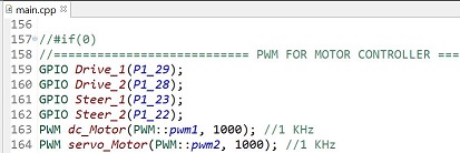
The motor controller is initialized by setting two PWM pins of SJone board to 1KHz frequency using the inbuilt functions provided Prof. Preetpal Kang (CMPE 244 instructor). Four GPIO pins are used as interrupt pins for both the dc motor and servo motor. Code snippet as follows:
We set the GPIO pins for acceleration and steering as output as follows:
Function to set the speed of the motor and the direction of the dc motor and servo motor is as follows:
Ultrasonic Sensor
For this project we used an ultrasonic sensor to find the distance for obstacle avoidance.
Initially we used Seeed Studio Ultrasonic Range Finder (SEN136B5B) which is similar to PING))) Ultrasonic Distance Sensor. The sensor has has 3 pins: Vcc, GND and SIG where SIG acts as input and output at the same time.
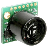
The sensor was initially working but due to erratic voltage supply to it, the sensor somehow got burned and stopped working. So we changed the sensor to LV Maxsonar EZ ultrasonic sensor.
The ultrasonic sensor interfaces using an ADC interface. The SJone board is equipped with an analog-to-digital converter which converts an analog signal (continuous voltage that varies over time) into corresponding digital values (discrete integers that approximate the input voltage). The 12-bit ADC operates on 3.3V which means that a voltage range between 0V and 3.3V can be divided into 212 or 4096 discrete steps. The sensor has 7 pins from which 3 pins are used to connect to the board: 1. Pin "+5" on sensor to Pin "3.3V" on SJone board. 2. Pin "GND" on sensor to Pin "Gnd" on SJone board. 3. Pin "AN" on sensor to Pin "A0-4" on SJone board.
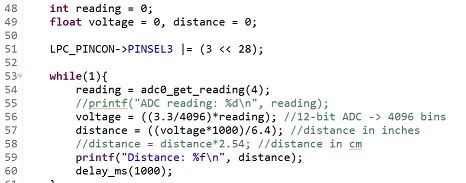
The sensor values are read using adc0_get_reading_function. The ADC values are then converted to voltage values and the voltage values to centimeters to measure the distance. x
Testing & Technical Challenges
My Issue #1
We faced some issues which we would like to mention and how we overcame those.
Hardware items: After the idea was finalized and the how-to-do stuff was imagined and designed,the initial problem was to where to find the materials,the hardware tools which would exactly meet the requirements of the project. After searching various hardware stores,we would a really nice place called the "TAP-PLASTICS" where the technician named Kevin was really helpful in his suggestions and the improvisations which can be used.
My Issue #2
Image Processing Module: It took some time for us to finalize the HSV platform for detecting the Fish.We initially tried converted the image to Grey Scale Platform,but we failed to track the image.Finding a Platform for Image Processing also took sometime,as we initially tried to use C++ for Image Processing Platform,but we failed to apply image processing algorithms which in future, we will work on it.
My Issue #3
Ultrasonic Sensor: We faced issues with ultrasonic sensor.Initially it worked well but due to some issues it did not give accurate values.We replaced the sensor with an higher quality sensor.The updated sensor is working accurately and helps in providing obstacle avoidance for the car.
Conclusion
The whole project experience was fun and very educational. At first we thought that Image Processing algorithms are available online, so just editing them will make our project work.But we learned a hard lesson that ,lot of our time would be saved if we write our own code instead of editing them.We learned to configure and use Nordic wireless module.We got to know how PWM Driver and Serial Communication works.
The project can be expanded by making it as an standlone project.We are learning to write a driver for interfacing the camera to the microprocessor,which soon we will be implementing in our project.
Project Video
Below is the link for our project :
https://www.youtube.com/watch?v=y4z0cLZsiMY
Project Source Code
References
Acknowledgement
We, the team of Bug-Rider would like to wholeheartedly thank our friend, our guide and our Professor Preetpal Kang for guiding us, encouraging us to do these projects and imparting knowledge and wisdom to us in our academics as well as for our career.Thank You Preet!
References Used
(1) http://www.socialledge.com/sjsu/index.php?title=Main_Page
(2) https://learn.adafruit.com/series/learn-arduino
(3) http://www.maxbotix.com/documents/LV-MaxSonar-EZ_Datasheet.pdf
Appendix
You can list the references you used.
