Difference between revisions of "S14: Anti-Crash Car"
Proj user22 (talk | contribs) (→Test Stage 3: Field Testing) |
(→Project Source Code) |
||
| (61 intermediate revisions by 2 users not shown) | |||
| Line 1: | Line 1: | ||
| − | |||
| − | |||
| − | |||
| − | |||
| − | |||
| − | |||
| − | |||
| − | |||
| − | |||
| − | |||
| − | |||
| − | |||
= Anti-Crash Car = | = Anti-Crash Car = | ||
| + | [[File:Cmpe146 S14 ACCAR Car.jpg|center|frame]] | ||
== Abstract == | == Abstract == | ||
| Line 17: | Line 6: | ||
== Objectives & Introduction == | == Objectives & Introduction == | ||
| − | + | The objectives of the project was to use concepts learned in class to put together a car that would avoid crashing into objects.The car is driven by the motors and steered by a single servo. It is guided by a compass which points to the direction of the destination set by the user. The compass determines this direction through calculations, comparing its current location (coordinates found by the GPS Receiver) with the destination's coordinates. To avoid collision with interfering obstacles, 3 sensors are used--one being sonar, two being infrared. | |
| − | |||
| − | The car is driven by the motors and steered by a single servo. It is guided by a compass which points to the direction of the destination set by the user. The compass determines this direction through calculations, comparing its current location (coordinates found by the GPS Receiver) with the destination's coordinates. To avoid collision with interfering obstacles, 3 sensors are used--one being sonar, two being infrared. | ||
| − | [[File:CMPE146 S14 ACCAR Car design.png|center|frame]] | + | [[File:CMPE146 S14 ACCAR Car design.png|500px|center|frame]] |
=== Team Members & Responsibilities === | === Team Members & Responsibilities === | ||
| Line 33: | Line 20: | ||
* <b>Koko Maung </b> | * <b>Koko Maung </b> | ||
** Car Kit Assembly | ** Car Kit Assembly | ||
| − | + | ** Servos/ Wheel Motor Module | |
| − | |||
** Infrared Sensor Module | ** Infrared Sensor Module | ||
** Sonar Sensor Module | ** Sonar Sensor Module | ||
** Compass Module | ** Compass Module | ||
| − | ** State Machine | + | ** System State Machine |
* <b>Matthew Pham</b> | * <b>Matthew Pham</b> | ||
| Line 160: | Line 146: | ||
== Design & Implementation == | == Design & Implementation == | ||
| − | |||
=== Hardware Design === | === Hardware Design === | ||
| + | Main Components: | ||
*SJ-one Board | *SJ-one Board | ||
*Rock Crawler | *Rock Crawler | ||
| Line 171: | Line 157: | ||
[[File:Cmpe146 S14 ACCAR Components.jpg|center|frame]] | [[File:Cmpe146 S14 ACCAR Components.jpg|center|frame]] | ||
| − | |||
| − | === | + | === Hardware Interface === |
[[File:Cmpe146_S14_ACCAR_System_Schematic.jpg|center|frame]][[File:Cmpe146_S14_ACCAR_Schematic_board.png|center|frame]] | [[File:Cmpe146_S14_ACCAR_System_Schematic.jpg|center|frame]][[File:Cmpe146_S14_ACCAR_Schematic_board.png|center|frame]] | ||
| − | === | + | === Software Design === |
| − | + | The system runs off of multiple FreeRTOS tasks running together. | |
| + | |||
| + | '''Sonar Task''' | ||
| + | |||
| + | The task for sonar is responsible for detecting objects from a user specified distance and updating a global "sonar" variable used by the other tasks. Detections closer to the sonar return greater values while detections farther away return lesser values. | ||
| + | |||
| + | '''Left and Right IR Tasks''' | ||
| + | |||
| + | The left and right infrared sensor tasks act the same way as the sonar's task. These tasks are also used for object detection. It updates global "left IR" and "right IR" variables to be used by other tasks. | ||
| + | |||
| + | '''GPS Task''' | ||
| + | |||
| + | The GPS task updates a struct named "coordinates" with GPS coordinates. This struct contains two double types (one for longitude and one for latitude). | ||
| + | |||
| + | '''Compass Task''' | ||
| + | |||
| + | The compass task also updates a global variable which indicates the angle at which the compass is directed (e.g. 0°-359°). | ||
| + | |||
| + | '''State Machine Task''' | ||
| + | |||
| + | This task includes the system state machine as shown in the [http://www.socialledge.com/sjsu/index.php?title=S14:_Anti-Crash_Car#Design_Flow Design Flow Diagram] | ||
| − | |||
==== Design Flow ==== | ==== Design Flow ==== | ||
[[File:Cmpe146_S14_ACCAR_Car_state_machine.png|center|frame]] | [[File:Cmpe146_S14_ACCAR_Car_state_machine.png|center|frame]] | ||
=== Implementation === | === Implementation === | ||
| − | |||
====State machine==== | ====State machine==== | ||
| Line 259: | Line 262: | ||
=====Pin Configuration===== | =====Pin Configuration===== | ||
| − | [[File:Cmpe146_S14_ACCAR_GPS_Pin_assignment.JPG | + | [[File:Cmpe146_S14_ACCAR_GPS_Pin_assignment.JPG]] |
{| class="wikitable" | {| class="wikitable" | ||
| Line 289: | Line 292: | ||
== Testing & Technical Challenges == | == Testing & Technical Challenges == | ||
| − | |||
| − | |||
| − | + | === Testing: === | |
| − | === Test Stage 1: Individual Peripherals === | + | ==== Test Stage 1: Individual Peripherals ==== |
In the first stage of testing, each individual peripheral was tested separately. | In the first stage of testing, each individual peripheral was tested separately. | ||
| − | ==== GPS Module ==== | + | ===== GPS Module ===== |
* Checked for UART communication | * Checked for UART communication | ||
** The console for the SJ One board should at least read characters (unreadable or unrecognized characters are a result of mismatched (GPS Receiver)<->(SJ One) baud rates) | ** The console for the SJ One board should at least read characters (unreadable or unrecognized characters are a result of mismatched (GPS Receiver)<->(SJ One) baud rates) | ||
| Line 305: | Line 306: | ||
** GPS Receiver was tested in open outdoors (The GPS Receiver was moved around EAST, WEST, NORTH, and SOUTH to check for change of data.) | ** GPS Receiver was tested in open outdoors (The GPS Receiver was moved around EAST, WEST, NORTH, and SOUTH to check for change of data.) | ||
| − | ==== Infrared Sensors ==== | + | ===== Infrared and Sonar Sensors ===== |
* Checked for correct functionality | * Checked for correct functionality | ||
** Checked whether sensor detected objects in front by analyzing converted values | ** Checked whether sensor detected objects in front by analyzing converted values | ||
** Checked whether values sent to board are consistent with proximity of objects in front of sensors | ** Checked whether values sent to board are consistent with proximity of objects in front of sensors | ||
| − | ==== | + | ===== Compass ===== |
| − | + | * The compass should return a value between 0 and 359 degrees to the SJ One Board | |
| − | + | ** NORTH: 0° | |
| − | * | + | ** WEST: 90° |
| + | ** SOUTH: 180° | ||
| + | ** EAST: 270° | ||
| − | === Test Stage 2: System State Cases with Peripherals === | + | ==== Test Stage 2: System State Cases with Peripherals ==== |
* Individual State Testing | * Individual State Testing | ||
| − | ** Interact with sensors to | + | ** Interact with sensors to control state machine paths |
** Analyze variables to verify correct conditions to state entry | ** Analyze variables to verify correct conditions to state entry | ||
** Print out current state upon entering state | ** Print out current state upon entering state | ||
| − | === Test Stage 3: Field Testing === | + | ==== Test Stage 3: Field Testing ==== |
After each individual peripheral has been thoroughly tested, the car was brought out for field testing (literally!). To test the car, the destination of the car was set to be equal to the car's current location plus a certain amount of coordinates away. The car was then dropped off and set to drive. The following criteria were to be met: | After each individual peripheral has been thoroughly tested, the car was brought out for field testing (literally!). To test the car, the destination of the car was set to be equal to the car's current location plus a certain amount of coordinates away. The car was then dropped off and set to drive. The following criteria were to be met: | ||
* The car should drive in the direction pointed to its destination | * The car should drive in the direction pointed to its destination | ||
| Line 327: | Line 330: | ||
* The car should move around obstacles present in its path | * The car should move around obstacles present in its path | ||
| − | |||
| − | |||
| − | + | === Issues: === | |
| − | === | + | ==== PWM API ==== |
| − | + | <b>Problems:</b> | |
| + | *Due to the SJ One Board's PWM API, PWMs connected to the SJ One Board must run at 50Hz. Although the servos and motors are capable of handling faster frequencies, they cannot handshake without matching. | ||
| − | Solution : We | + | <b>Solution:</b> |
| − | + | *We end up using 50Hz and we had to operate motor at slower speed. | |
| − | |||
| − | + | ==== Software Related Crashing ==== | |
| + | <b>Problems:</b> | ||
| + | * Combinations of function calls and interrupts would sometimes crash the system. | ||
| − | + | <b>Solution:</b> | |
| + | * Convert functions for GPS, motor, state machine, sensors, etc., to tasks | ||
| + | **As tasks, the functions were able to run in the background | ||
| − | === | + | ==== Compass Issues ==== |
| + | <b>Problems:</b> | ||
| + | * The first compass (UBLOXLEA-6) ordered was not compatible with the SJ One Board | ||
| + | ** It was designed for Plug-n-Play with specific Android related devices. | ||
| + | ** There was no specifications document for individual pins of the device. | ||
| + | * The second compass (HMC58830) ordered had incomplete datasheets. | ||
| + | ** A search online was made for further specifications, but no documentation was found. | ||
| − | + | <b>Solution:</b> | |
| − | + | * A third compass (CMPS10) was bought. However, it had trouble returning values pointing in the NORTH-EAST direction (270° to 359°). | |
| − | + | ** All expected values located in that range returned inconsistently incorrect values instead. | |
| + | ** During Field Testing, it was found that the compass DOES guide the car to its destination. It was trying to adjust the car left and right. However, since the compass value is inconsistent, that car was not able to reach destination. | ||
| + | * Due to having to reorder three different compasses, time had taken its toll. The compass still not able to output correct result. | ||
| + | *According to Professor Preet, the inconsistency might have to do with our hardware design. Our compass is too close to motor which is producing magnetic field. We will update the result once we found the solution and the cause. | ||
| − | === | + | ==== Time management issue ==== |
<b>Problems:</b> | <b>Problems:</b> | ||
| − | * | + | *We were spending most of the time implementing and testing it in control environment that we only have one day left to field test it. |
| + | **In our software design, when compass decide to turn left, right or mid, only one sensor is driving and making decision for the car. Therefore, when turning left, if there is an object at either front or right side, it will crash into it. | ||
<b>Solution:</b> | <b>Solution:</b> | ||
| + | *Since we field tested one day before the demo, we didn't have enough time to come up with new algorithm. However, by adding case statements, to check other sensors, after compass decision can solve above issue. | ||
| − | |||
| − | |||
| − | + | ==== GPS Issues ==== | |
| − | |||
| − | |||
| − | === GPS Issues === | ||
<b>Problems:</b> | <b>Problems:</b> | ||
* The ordered GPS Receiver (LS20031) was not the one received (LS23060). | * The ordered GPS Receiver (LS20031) was not the one received (LS23060). | ||
| Line 381: | Line 392: | ||
[[File:Cmpe146_S14_ACCAR_RealTerminal.jpg|center|frame]] | [[File:Cmpe146_S14_ACCAR_RealTerminal.jpg|center|frame]] | ||
| − | == | + | == Conclusion == |
| − | + | Much of the car's functionalities were implemented correctly. | |
| − | + | From the project, the team gained firsthand experience after utilizing concepts and protocols such as state machines, ADC, UART, and I2C. Also, the team learned how to test individual modules and the system itself. Sensors were tested manually to make sure that they functional and were outputting correct values. System states had to be tested with great attention to detail to make sure the system transitioned to the correct state. The team learned the benefits of implementing functions as tasks to allow the system to execute multiple tasks concurrently. Also, the team learned how to work together and work efficiently by dividing up tasks and working side by side to design, implement, and test the project. As a result, we were able to deliver the anti-crash car that is nearly complete. | |
| − | == | + | <gallery widths=300px heights=300px> |
| − | + | File:Cmpe146 S14 ACCAR Car1.jpg| | |
| + | File:Cmpe146 S14 ACCAR Car2.jpg| | ||
| + | File:Cmpe146 S14 ACCAR Car3.jpg| | ||
| + | </gallery> | ||
=== Project Video === | === Project Video === | ||
| − | Upload a video of your project and post the link here. | + | Upload a video of your project and post the link here. |
=== Project Source Code === | === Project Source Code === | ||
| − | + | * [https://sourceforge.net/projects/sjsu/files/CmpE244_SJSU_S2014/ Sourceforge source code link] | |
== References == | == References == | ||
=== Acknowledgements === | === Acknowledgements === | ||
| − | We would like to | + | We would like to thanks Dr. Ozemek for giving us detailed knowledge of how circuits and components works. |
| − | We would like to | + | We would like to thanks Preetpal Kang for teaching us how to use microcontrollers and FreeRTOS. |
| − | We would like to | + | We would like to thanks James Loo for guiding me [Koko] throughout this whole project, making sure our project was being put together correctly. |
=== References Used === | === References Used === | ||
| − | + | Sonar Sensor - http://www.robotshop.com/en/devantech-ultrasonic-range-finder-srf08.html | |
| + | |||
| + | IR Sensors - http://www.google.com/url?q=http%3A%2F%2Fwww.robotshop.com%2Fen%2Fsharp-gp2y0a21yk0f-ir-range-sensor.html%3F___SID%3DU&sa=D&sntz=1&usg=AFQjCNF_wpjNxO10zTRNNgvF22dwLX-BBg | ||
| − | http://www.robotshop.com/en/devantech- | + | Compass - http://www.robotshop.com/en/devantech-tilt-magnetic-compass.html |
| − | + | GPS Receiver - https://www.sparkfun.com/products/8975 | |
| + | https://dallasmakerspace.org/wiki/LS20031_GPS | ||
| − | http:// | + | NMEA Commands - http://api.ning.com/files/WrydAs2CdNAMGhy*O-mvQMNhGW6Mmt-2RUB2Jb1odwCMia*dzrbnJWicJlJ4D9KxRkh6huPt4fDP14imYTC2D1ozEw-k6Jq-/MTKNMEAPROPRIETARYCOMMAND.pdf |
| − | + | Checksum Calculator - http://www.hhhh.org/wiml/proj/nmeaxor.html | |
=== Appendix === | === Appendix === | ||
You can list the references you used. | You can list the references you used. | ||
Latest revision as of 00:02, 7 August 2014
Contents
- 1 Anti-Crash Car
Anti-Crash Car
Abstract
This project involves a GPS-controlled car that drives to a user determined destination. To prevent self-damage, when an obstacle is in its path, the car will move around the obstacle and determine a new path towards the destination. In addition, any time the car cannot move around the obstacle (all sides are blocked), the car will stop.
Objectives & Introduction
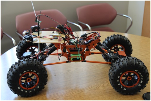
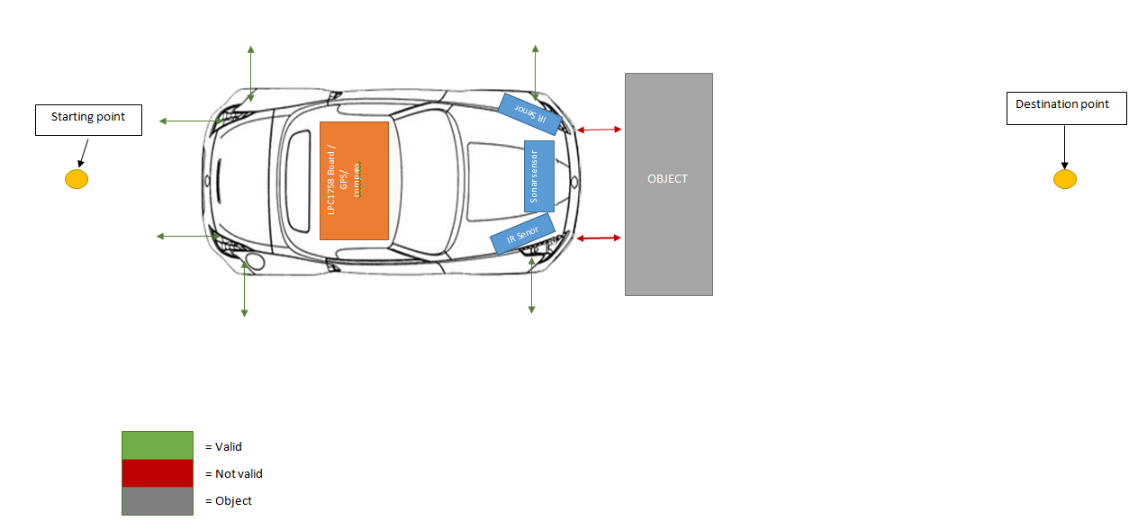
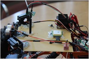
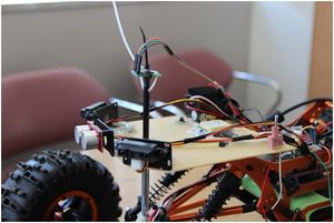
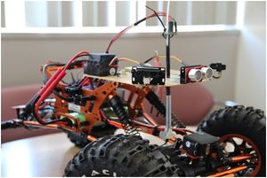
The objectives of the project was to use concepts learned in class to put together a car that would avoid crashing into objects.The car is driven by the motors and steered by a single servo. It is guided by a compass which points to the direction of the destination set by the user. The compass determines this direction through calculations, comparing its current location (coordinates found by the GPS Receiver) with the destination's coordinates. To avoid collision with interfering obstacles, 3 sensors are used--one being sonar, two being infrared.
Team Members & Responsibilities
- Geff Lozano
- Infrared Sensor Module
- GPS Module
- Parser
- Information Processing
- System State Machine
- Koko Maung
- Car Kit Assembly
- Servos/ Wheel Motor Module
- Infrared Sensor Module
- Sonar Sensor Module
- Compass Module
- System State Machine
- Matthew Pham
- GPS Module
- UART Interface
- Parser
- Information Processing
- System State Machine
- GPS Module
Schedule
| Week# | Date | Task | Description |
|---|---|---|---|
| 1 | 3/23 | Planning | Top-Level System Drafting |
| 2 | 3/30 | Top-Level System Design | Went through many drafts |
| 3 | 4/6 | Order Parts | Ordered GPS/compass unit, sonar sensor, IR sensor, and necessary accessories. |
| 4 | 4/13 | Assign peripheral responsibilities | Divided the work. |
| 5/6 | 4/20 | Peripheral Interfacing | GPS, Infrared, Sonar; No communication with GPS; Burned GPS; |
| 7 | 4/27 | System State Machine Implementation | Redrafted Original State Machine |
| 8 | 5/4 | Implementing | Started implementing State Machine with Peripheral devices together. Figured out that we purchased incorrect GPS / compass device. |
| 8 | 5/11 | Implementing | State machine and peripheral devices are working the we we predicted. Except compass. Order new compass |
| 8 | 5/18 | Implementing / Testing | Implementing State machine with compass. Did field testing. |
| 8 | 5/22 | Demo |
Parts List & Cost
| Qty | Part | Price |
|---|---|---|
| 1 | RC Rock Crawler | $200.86 |
| 1 | SRF08 Ultrasonic Range Finder | $54.30 |
| 4 | Sensor Housing MPSH-01 | $19.8 |
| 3 | GP2Y0A21YK0F IR Sensor - 10cm to 80cm | $59.4 |
| 3 | SIRC-01 Sensor Cable | $5.85 |
| 1 | 3DR GPS Module w/ Compass | $53.35 |
| 1 | Battery | $25.00 |
| 1 | FTDI Cable | $14.97 |
| 1 | GPS Receiver - LS20031 5Hz (66 Channel) | $59.95 |
| 1 | Compass Module 3-Axis HMC5883L | $15.99 |
| Total | $509.47 |
Design & Implementation
Hardware Design
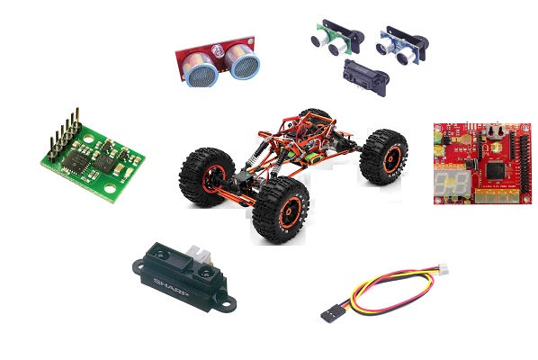
Main Components:
- SJ-one Board
- Rock Crawler
- IR sensor
- Sonar sensor
- GPS module
- Compass module
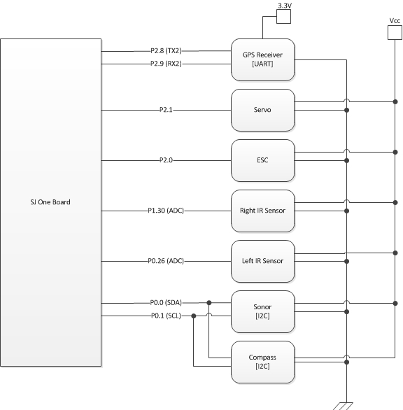
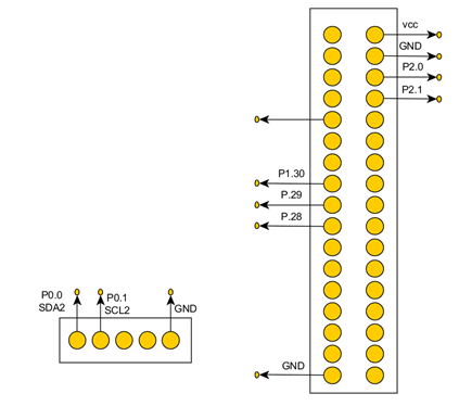
Hardware Interface
Software Design
The system runs off of multiple FreeRTOS tasks running together.
Sonar Task
The task for sonar is responsible for detecting objects from a user specified distance and updating a global "sonar" variable used by the other tasks. Detections closer to the sonar return greater values while detections farther away return lesser values.
Left and Right IR Tasks
The left and right infrared sensor tasks act the same way as the sonar's task. These tasks are also used for object detection. It updates global "left IR" and "right IR" variables to be used by other tasks.
GPS Task
The GPS task updates a struct named "coordinates" with GPS coordinates. This struct contains two double types (one for longitude and one for latitude).
Compass Task
The compass task also updates a global variable which indicates the angle at which the compass is directed (e.g. 0°-359°).
State Machine Task
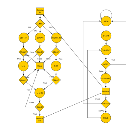
This task includes the system state machine as shown in the Design Flow Diagram
Design Flow
Implementation
State machine
Our State machine is designed with
 STOP :       Forever stop loop
 START:       Car turned on / reset button is pressed
 CURRENT:  1. current location is collected from GPS
           2. set L,M,R = 0,0,0
           3. ( destination == current) ? if true : stop ; else : compass
 COMPASS:  1. check head direction
           2. check where the coordinate of destination
           3. set L,M,R bits accordingly
           4. move to decision
 DECISION: 1. depending on the L,M,R bit it will make decision on which sensor to check
           2. ( Object )? if : next sensor; else move
 MOVE :    1. move accordingly
           2. move back to current
Servo and Wheel motor Communication (PWM)
Servo and Wheel motor communication is done by using PWM communication. Interface for PWM is already given by Professor Preet.
1. We must set the pin that we want to use with the waveform period
2. set percentage of waveform to be stay at high.
  eg.PWM pwm1(PWM::pwm1, 50); // pw1 = p0.0, period = 50
     pwm1.set(10);            // percent = 10   1/5 of the time signal gonna be high
Sonar and Compass Communication (I2C)
Sonar and Compass communication is done by using I2C communication. Interface for I2C is already given by Professor Preet. Since I2C module already take care of turning the LSB to high and low accordingly, we don't have to worry about it.
1. Get device address from datasheet.
2. If device requires commands to perform operation, write command to appropriate register.
3. Read information from appropriate register.
notice : If you try to read value before its ready, you will get zero.
  eg. i2c.writeReg(0xE0,0x00,0x50); //writing: device address = 0xE0, register address = 0x00, writing value = 0x50;
      char high_byte = i2c.readReg(0xE0, 0x02); // reading: device address = 0xE0, register address = 0x02
      char low_byte = i2c.readReg(0xE0, 0x03);  // register address = 0x02
Infrared Communication (ADC)
Infrared communication is done by using ADC communication. Interface for ADC is already given by Professor Preet.
1. set a pin for ADC
2. select mode
3. initialize the pin
4. read value at appropriate time.
  // initialization
  eg. LPC_PINCON -> PINSEL1 |= ( 1 << 20 ); // P0.30
      LPC_PINCON -> PINMODE1 |= ( 2 << 20 ); // output mode
      adc0_init(); // initilize
  // reading
      IR_Left_distance = adc0_get_reading(4);
GPS Communication (UART)
The GPS Receiver communicates with the SJ One board through UART via NMEA sentences.
Examples:
- The user can configure the update (baud) rate of the GPS module with the following example commands:
- 38400bps - $PMTK251,38400*27<CR><LF>
- 57600bps - $PMTK251,57600*2C<CR><LF>
- The user can filter out unwanted NMEA sentences with the following example commands:
- Only RMC at 1Hz - $PMTK314,0,1,0,0,0,0,0,0,0,0,0,0,0,0,0,0,0,0,0*29<CR><LF>
- Only GGA at 1Hz - $PMTK314,0,0,0,1,0,0,0,0,0,0,0,0,0,0,0,0,0,0,0*29<CR><LF>
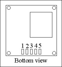
Pin Configuration
| Pin | Name | Description |
|---|---|---|
| 1 | VCC | Power input |
| 2 | RX | Data input (TTL level) |
| 3 | TX | Data output (TTL level) |
| 4 | GND | Ground |
| 5 | GND | Ground |
Testing & Technical Challenges
Testing:
Test Stage 1: Individual Peripherals
In the first stage of testing, each individual peripheral was tested separately.
GPS Module
- Checked for UART communication
- The console for the SJ One board should at least read characters (unreadable or unrecognized characters are a result of mismatched (GPS Receiver)<->(SJ One) baud rates)
- Checked for data consistency and reliability
- The GPS Receiver must first be able to detect any nearby satellites
- No LED blinking or inconsistent blinking rates are a result of satellites not being detected.
- GPS Receiver was tested in open outdoors (The GPS Receiver was moved around EAST, WEST, NORTH, and SOUTH to check for change of data.)
Infrared and Sonar Sensors
- Checked for correct functionality
- Checked whether sensor detected objects in front by analyzing converted values
- Checked whether values sent to board are consistent with proximity of objects in front of sensors
Compass
- The compass should return a value between 0 and 359 degrees to the SJ One Board
- NORTH: 0°
- WEST: 90°
- SOUTH: 180°
- EAST: 270°
Test Stage 2: System State Cases with Peripherals
- Individual State Testing
- Interact with sensors to control state machine paths
- Analyze variables to verify correct conditions to state entry
- Print out current state upon entering state
Test Stage 3: Field Testing
After each individual peripheral has been thoroughly tested, the car was brought out for field testing (literally!). To test the car, the destination of the car was set to be equal to the car's current location plus a certain amount of coordinates away. The car was then dropped off and set to drive. The following criteria were to be met:
- The car should drive in the direction pointed to its destination
- The car should stop when it has reached its destination
- The car should move around obstacles present in its path
Issues:
PWM API
Problems:
- Due to the SJ One Board's PWM API, PWMs connected to the SJ One Board must run at 50Hz. Although the servos and motors are capable of handling faster frequencies, they cannot handshake without matching.
Solution:
- We end up using 50Hz and we had to operate motor at slower speed.
Software Related Crashing
Problems:
- Combinations of function calls and interrupts would sometimes crash the system.
Solution:
- Convert functions for GPS, motor, state machine, sensors, etc., to tasks
- As tasks, the functions were able to run in the background
Compass Issues
Problems:
- The first compass (UBLOXLEA-6) ordered was not compatible with the SJ One Board
- It was designed for Plug-n-Play with specific Android related devices.
- There was no specifications document for individual pins of the device.
- The second compass (HMC58830) ordered had incomplete datasheets.
- A search online was made for further specifications, but no documentation was found.
Solution:
- A third compass (CMPS10) was bought. However, it had trouble returning values pointing in the NORTH-EAST direction (270° to 359°).
- All expected values located in that range returned inconsistently incorrect values instead.
- During Field Testing, it was found that the compass DOES guide the car to its destination. It was trying to adjust the car left and right. However, since the compass value is inconsistent, that car was not able to reach destination.
- Due to having to reorder three different compasses, time had taken its toll. The compass still not able to output correct result.
- According to Professor Preet, the inconsistency might have to do with our hardware design. Our compass is too close to motor which is producing magnetic field. We will update the result once we found the solution and the cause.
Time management issue
Problems:
- We were spending most of the time implementing and testing it in control environment that we only have one day left to field test it.
- In our software design, when compass decide to turn left, right or mid, only one sensor is driving and making decision for the car. Therefore, when turning left, if there is an object at either front or right side, it will crash into it.
Solution:
- Since we field tested one day before the demo, we didn't have enough time to come up with new algorithm. However, by adding case statements, to check other sensors, after compass decision can solve above issue.
GPS Issues
Problems:
- The ordered GPS Receiver (LS20031) was not the one received (LS23060).
- There were no specific datasheets for the acquired model (LS23060).
- The datasheet for LS20031 was used instead. NOTE: Use LS20031 specifications with caution.
- The baud rate specified in the datasheet (57600bps) did not match the baud rate of the acquired GPS Receiver (38400bps).
- Communication between the GPS Receiver and the SJSU development board was not possible due to mismatched baud rates. The GPS Receiver baud rate cannot even be set to a desired baud rate through PTMK commands without being in sync with the command sender in the first place.
Solution:
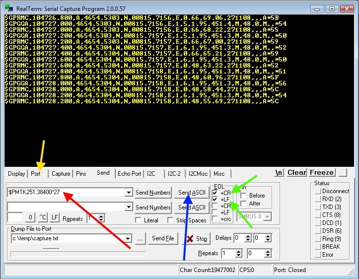
The solution was to use an FDTI cable (UART to USB) with Realterminal (http://realterm.sourceforge.net/index.html#downloads_Download) for synchronization.
- Using Realterminal, users can determine the baud rate of the GPS Receiver through trial and error--changing the port baud rate until NMEA sentences are displayed.
- e.g. $--GGA,hhmmss.ss,llll.ll,a,yyyyy.yy,a,x,xx,x.x,x.x,M,x.x,M,x.x,xxxx.
- See GPS - NMEA sentence information for more examples.
- Only until the Port is initially synced with the GPS Receiver, users cannot set the GPS Receiver to a desired baud rate. When the port is in sync, the following actions can be taken:
- With Realterminal open, click the Send Tab and check "+CR" and "+LF" flags.
- Send the string "$PMTK314,-1*04" as ASCII to reset the GPS to its default configuration. The baud rate will then be reset to 38400bps.
- Now the SJSU development board can communicate through PTMK commands at UART - 38400bps.
Conclusion
Much of the car's functionalities were implemented correctly. From the project, the team gained firsthand experience after utilizing concepts and protocols such as state machines, ADC, UART, and I2C. Also, the team learned how to test individual modules and the system itself. Sensors were tested manually to make sure that they functional and were outputting correct values. System states had to be tested with great attention to detail to make sure the system transitioned to the correct state. The team learned the benefits of implementing functions as tasks to allow the system to execute multiple tasks concurrently. Also, the team learned how to work together and work efficiently by dividing up tasks and working side by side to design, implement, and test the project. As a result, we were able to deliver the anti-crash car that is nearly complete.
Project Video
Upload a video of your project and post the link here.
Project Source Code
References
Acknowledgements
We would like to thanks Dr. Ozemek for giving us detailed knowledge of how circuits and components works.
We would like to thanks Preetpal Kang for teaching us how to use microcontrollers and FreeRTOS.
We would like to thanks James Loo for guiding me [Koko] throughout this whole project, making sure our project was being put together correctly.
References Used
Sonar Sensor - http://www.robotshop.com/en/devantech-ultrasonic-range-finder-srf08.html
Compass - http://www.robotshop.com/en/devantech-tilt-magnetic-compass.html
GPS Receiver - https://www.sparkfun.com/products/8975 https://dallasmakerspace.org/wiki/LS20031_GPS
Checksum Calculator - http://www.hhhh.org/wiml/proj/nmeaxor.html
Appendix
You can list the references you used.
