Difference between revisions of "S24: Team TerraByte"
(→Printed Circuit Board) |
|||
| Line 1: | Line 1: | ||
| − | == | + | == TerraByte == |
| − | |||
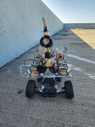
[[File:Tb.jpeg|400px]] | [[File:Tb.jpeg|400px]] | ||
<BR/> | <BR/> | ||
Revision as of 06:03, 25 May 2024
Contents
TerraByte
Abstract
<2-3 sentence abstract>
Introduction
The project is divided into 5 modules:
- Sensor Node
- Motor Node
- Driver Node
- Geo Controller Node
- Android App
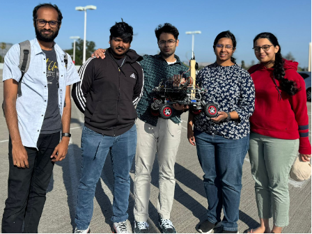
Team Members & Responsibilities
Gitlab Project Link - C243_TerraByte
| Module | Owner | Supporter |
|---|---|---|
| Sensor + Bridge | Vamsi Rushi Dhanekula | - |
| Driver + LCD | Minal Upadhye | Susmitha |
| Motor + ESC | Susmitha Ganesh | Minal |
| GPS + Geo Controller | Harikrishnan Kokkanthara Jeevan | - |
| App | Dikshant Kotla | Vamsi |
- Sensor & Bridge
- Motor
- Geographical
- Driver & LCD
- Android Application
- Link to Gitlab user1
Schedule
| Week# | Start Date | End Date | Task | Status |
|---|---|---|---|---|
| 1 | 03/04/2024 | 03/10/2024 |
|
Completed |
| 2 | 03/04/2024 | 03/10/2024 |
|
Completed |
| 3 | 03/11/2024 | 03/17/2024 |
|
Completed |
| 4 | 03/18/2024 | 03/24/2024 |
|
Completed |
| 5 | 03/25/2024 | 03/31/2024 |
|
Completed |
| 6 | 04/01/2024 | 04/07/2024 |
PROTOTYPE 1
|
Completed |
| 7 | 04/08/2024 | 04/14/2024 |
|
Completed |
| 8 | 04/15/2024 | 04/21/2024 |
PROTOTYPE 2
|
Completed |
| 9 | 04/22/2024 | 04/28/2024 |
|
Completed |
| 10 | 04/29/2024 | 05/05/2024 |
PROTOTYPE 3
|
Completed |
| 11 | 05/06/2024 | 05/12/2024 |
PROTOTYPE 4
|
Completed |
| 12 | 05/13/2024 | 05/19/2024 |
|
Completed |
Parts List & Cost
| Item# | Part Desciption | Vendor | Qty | Cost |
|---|---|---|---|---|
| 1 | RC Car - Traxxas Slash 2Wd BL | Traxxas [1] | 1 | $260.00 |
| 2 | SJ2 boards | CMPE SCE | 4 | $50.00 each |
| 3 | CAN Transceivers | Adafruit [2] | 4 | $3.95 each |
| 4 | LCD module 20*4 | GeekPi [3] | 1 | $10.99 |
| 5 | Bluetooth module | Adafruit [4] | 1 | $17.50 |
| 6 | Ultrasonic Sensors | Adafruit [5] | 4 | $6.95 each |
| 7 | GPS module | Adafruit [6] | 1 | $29.95 |
| 8 | Compass | Adafruit [7] | 1 | $29.90 |
| 9 | GPS Antenna | Antenna[8] | 1 | $8.90 |
| 10 | RPM Sensor | Reed switch [9] | 1 | $7.90 |
| 11 | DB9 connector female | Amazon [10] | 1 | $9.99 |
| 12 | Jumper wires | Amazon [11] | 2 | $6.98 each |
| 13 | Prototyping Board | Amazon [12] | 2 | $7.90 |
Printed Circuit Board
To handle the sheer complexity of connections, a custom PCB was considered as early as the prototype 1. Designed in KiCAD, from schematic capturing to PCB layout.
CAN Communication
<Talk about your message IDs or communication strategy, such as periodic transmission, MIA management etc.>
Hardware Design
<Show your CAN bus hardware design>
DBC File
Gitlab link to your DBC file -- https://gitlab.com/minalupadhye/C243_terrabyte/-/blob/master/dbc/project.dbc?ref_type=heads
Sensor Controller & Bridge
<Picture and link to Gitlab>
Hardware Design
Software Design
<List the code modules that are being called periodically.>
Technical Challenges
< List of problems and their detailed resolutions>
Driver Controller & LCD
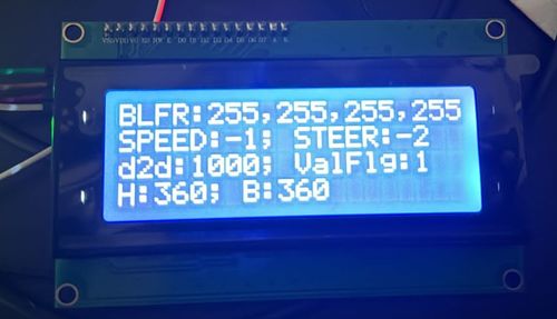
The LCD is a GeekPi 20x4 display using I2C. LCD displays some critical information during runtime which is critical for debugging. This information is split into 4 lines.
- Line1 displays sensor data from 4 sensors in the sequence Back(Rear), Left, Front, Right.
- Line2 displays command to motor from driver which are two signals: the speed (forward, stop, reverse) and steer values (left, right, straight).
- Lines 3 and 4 display information related to Geo module. Line 3 displays distance to destination and whether the current coordinates are valid (valid flag).
- Line4 displays current heading and bearing values from compass.
Hardware Design
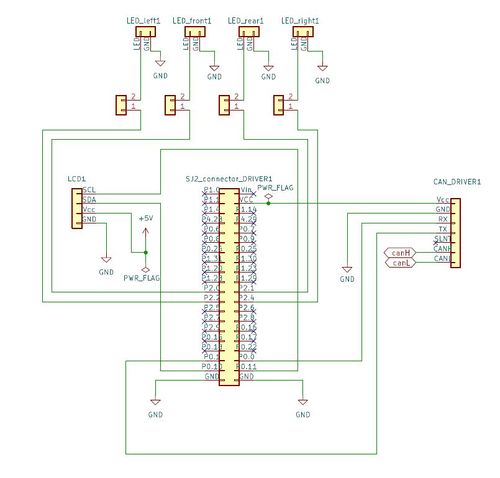
The SJ2 board hosting the driver module is connected to -
- CAN bus :
- LCD on I2C :
- Sensor LEDs :
Software Design
Driver module has 2 main objectives
- Process the input from sensor and geo module and provide control output to motor module.
- Display important information on the LCD.
Driver_logic() is the core part which manages the entire module.
Core Logic
if (obstacle_avoidance_flag) {
   motor_control_to_transmit = obstacle_avoidance();
 } else {
   motor_control_to_transmit = waypoint_algo(received_geo_status);
 }
Technical Challenges
< List of problems and their detailed resolutions>
Motor Controller
Hardware Design
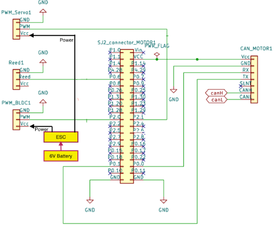
The motor controller, is the SJ2 board linked to powertrain, wheel encoder and CAN transceiver, which manages the motor's operation. It follows the direction and speed instructions provided by the Driver module. Additionally, it measures the wheel speed and maintains the preset speed across different terrains. This wheel speed data is transmitted to the Sensor-Bridge module for display on the Android App.
Powertrain
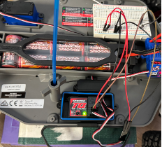
We used Traaxas Slash XL5 RWD for this project. The ESC (XL-5), BLDC motor, servo motor and battery come with the RC car. The 6V 3000mAh NiMH battery powers the ESC (XL-5), servo and BLDC motor. The ESC controls the BLDC however the servo is not connected via the ESC. The BLDC controls the forward, reverse and brake motion of the car along with the respective speed in the forward and reverse direction. The servo controls the steer angle. Brake and speed in both forward and reverse in case of BLDC motor and steer angle in case of Servo motor are controlled by PWM signals.
The ESC operates in 3 different modes as per the user manual, we choose to operate the car in Training mode where the forward and reverse speeds are half its original speeds. The maximum speed the car could reach is around 30Kmph in this mode. This mode can be set by long pressing the button on the ESC and releasing the button when there are 3 consecutive red blinks.
For the RC car the PWM signals are provided by the Radio Transmitter + Remote. We tried to understand the sequence of PWM that is to be provided to keep the ESC calibrated, for forward, reverse and brake by providing the commands on the remote and checking the waveform on oscilloscope.
The following were our observations which helped us develop motor control module:
| STATE | PWM | COMMENTS |
|---|---|---|
| ESC Calibration | 15% |
|
| Forward | 15.1% to 20% | Speed increases with the PWM dutycycle |
| Brake |
| |
| Reverse | 10% to 14.9% | Speed increases with the decrease in PWM dutycycle |
| Right | 15.1% to 20% | Angle increases with the PWM dutycycle |
| Left | 10% to 14.9% | Angle increases with decrease in PWM dutycycle |
| No steer | 15% |
Wheel Encoder
We opted reed switch for wheel encoding.
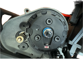
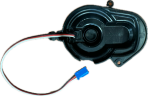
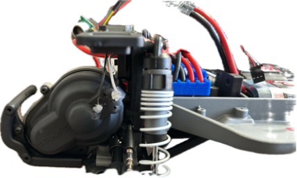
Placement : The magnet, along with its holder, was positioned on the spur gear, while the reed switch was housed within the casing covering the spur gear. The reed switch is connected between GPIO pin and ground. (NOTE: All GPIO pins of SJ2 board are pulled up to 3.3 V).
The reed switch is usually open (giving a 3.3V when observed on oscilloscope) but when it crosses the magnet the reed switch closes giving a 0V. The number of edge falls in a minute gives the rpm. This is converted into linear speed by considering the circumference of wheel and gear to wheel ratio (since the wheel encoder was placed in the spur gear every 2.73 rotations of spur gear yields 1 rotation of wheel).
Software Design
<List the code modules that are being called periodically.>
Technical Challenges
< List of problems and their detailed resolutions>
Geographical Controller
The geo controller has a dedicated SJ2 board attached to the CAN bus via a transceiver. The main task of the geo controller is to provide the driver node with directions to the destination location.
The geo node is attached with GPS and compass modules for this task.
Hardware Design
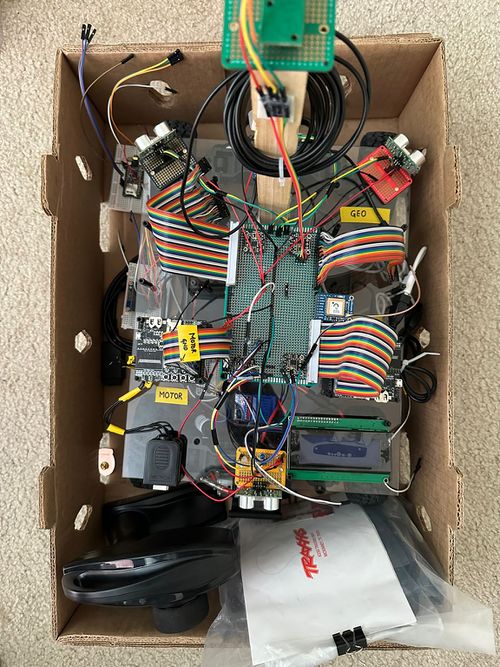
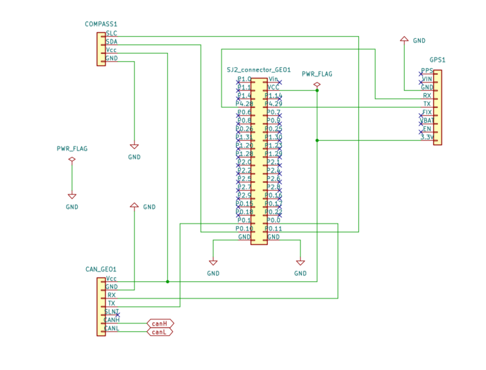
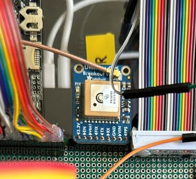
The following image shows the hardware connections of the GEO node
GPS Module
The GPS module used is an Adafruit Breakout V3, PA1616S
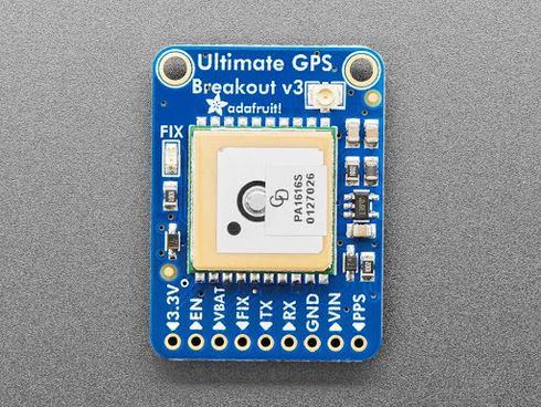
- It is a UART-based module that runs at 9600bps by default and can be configured up to 115200bps.
- It is attached to the SJ2 board on UART3 on pins P4.28(TX3) and P4.29(RX3).
- The TX is connected to the RX of the GPS and the RX pin is connected to the TX of the GPS.
- The GPS module outputs various NMEA strings like $GPGLL, $GPGSA etc… out of which we are concerned with only 1 type of string which is the $GPGGA - Global Positioning Systems Fix Data.
- Once the GPS gets a fix, the fix LED on the module will start blinking every 15 seconds.
- a button cell CR1220 is added to the GPS module to hotstart the module and get a fix faster
The $GPGGA string is of the format:
- $GPGGA,HHMMSS.SS,DDMM.MMMMM,K,DDDMM.MMMMM,L,N,QQ,PP.P,AAAA.AA,M,±XX.XX,M, SSS,RRRR*CC<CR><LF>
| Name | Example | Description |
|---|---|---|
| Message ID | $GPGGA | GGA protocol header |
| UTC Time | 002153.000 | hhmmss.sss |
| Latitude | 3342.6618 | dddmm.mmmm |
| N/S indicator | N | North or South Indicator |
| Longitude | 11751.3858 | dddmm.mmmm |
| E/W Indicator | W | East or West Indicator |
| Position Fix Indicator | 1 | Indicates if there is a satellite fix |
| Satellite Used | 10 | Range 0 to 12 |
| HDOP | 1.2 | Horizontal Dilution of Precision |
| MSL Altitude | 27.0 | |
| Units | M | |
| Geoid Separation | -34.2 | Geoid-to-ellipsoid separation. Ellipsoid altitude = MSL Altitude + Geoid Separation |
| Units | M | |
| Age of Diff. Corr. | Null fields when DGPS is not used | |
| Diff. Ref. Station ID | 000 | |
| Checksum | *5E | |
| <CR><LF> | End of Message termination |
- We are interested in the Message ID, latitude, N/S indicator, Longitude, E/W Indicator, and Position Fix Indicator, which the parsing algorithm will parse from the line buffer.
- The output will be the current location in terms of latitude and longitude of the format (3342.6618, 11751.3858).
Compass
Important Note to future students: Under no circumstances buy a compass that you have to manually calibrate like the LSM303AGR or LSM303DLHC (see technical challenges for more information)
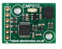
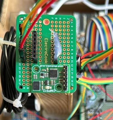
- The compass module used is a CMPS12 from Bosch. It was chosen because it works out of the box, is tilt-calibrated, and does not require any additional calibration to account for the magnetic declination, soft iron, and hard iron offsets.
- The compass is interfaced to the SJ2 board using the I2C_2 pins P0.10 (SDA) and P0.11 (SCL) respectively.
Software Design
The Geo node software was split into the following modules to efficiently handle the code:
- Can
- Handles the can initialization, encode & send and the MIA configuration
- Checkpoint
- The checkpoint algorithm to help the car reach the destination at a particular location
- Geo Message Bank
- Handles all the sending and receiving of the CAN messages to and from the Geo node in a single place
- Geo Status
- The main function used to gather all the geo node details and pack them into a CAN message
- GPS
- The GPS parsing Algorithm
- LED handle
- Used to handle the SJ2 Board's LEDs for debugging and indication purposes while the car is running
- Line buffer
- Support Module for the GPS parser
Initialization Phase
- The GPS module can and should be configured to only output GPGGA strings during the initialization phase of the scheduler. This makes it easier to have a smaller line buffer and less overhead
- The command used: "$PMTK314,0,0,0,1,0,0,0,0,0,0,0,0,0,0,0,0,0,0,0*29\r\n"
- Apart from this, the GPS module along with the SJ2 UART should be raised to 115200bps to get the best possible speed when running the GPS_run_once() function at 20hz. However, we found that raising the speed to 115200 was not working. See the technical challenges section for more details.
- Very little configuration during the initialization phase is required to start getting the heading values from the compass in fact, if you are using I2C_2 by default I2C is initialized with 400khz and you don’t need to do any setup.
Main Loop
- The geo controller's main task is to send a status message ‘GEO_STATUS’ to the driver node. This frame contains details like the heading, bearing, distance to destination, and some flags to help the car reach the destination.
- All function calls CAN receive, CAN send and gps_run_once are called in 20hz frequency.
- gps_run_once() function call fetches the latest NMEA GPGGA string from the line buffer and parses it to extract the latitude and longitude along with GPS fix data. On successful parsing of the string, a debug flag is also set. If the parsing was successful and a fix was present an LED on the SJ2 board was lit up.
- The destination to which the car has to reach set from the Android app is sent by the SENSOR_BRIDGE module via CAN.
- Once the destination co-ordinate has been received the bearing and distance to the destination are computed.
- To compute the bearing we use both coordinates the current location received from the GPS module and the destination location received from the SENSOR_BRIDGE node. The values are fed into the below formula and converted into degrees from radians.
- To compute the distance to the destination the haversine formula is used and output is formatted into meters for better accuracy. If the distance is less than 3m a flag is set once to indicate that the final destination is reached. More on this in the technical challenges section.
- To compute the heading the geo_status() function simply fetches the latest values from the compass and applies the constants described in the datasheet.
- Once all this data is computed the ‘GEO_STAUS’ message is populated and then sent to the driver node in the CAN transmission function call.
- A message bank module was adopted where all messages to be sent and received from the CAN are processed.
checkpoint Algorithm
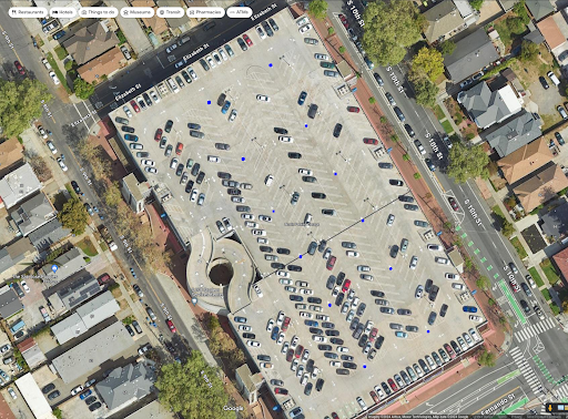
The checkpoint algorithm is used to make the navigation of the car easier in the final demo location. it follows the closest checkpoints from source to destination in an effective manner
- 37.339725 ,-121.881119
- 37.339764 ,-121.881073
- 37.339581 ,-121.880928
- 37.339539 ,-121.881035
- 37.339375 ,-121.880890
- 37.339436 ,-121.880760
- 37.339291 ,-121.880646
- 37.339226 ,-121.880745
- 37.339088 ,-121.880630
- 37.339134 ,-121.880516
- 37.338947 ,-121.880371
- 37.338882 ,-121.880486
- The checkpoints shown above were used as inputs to the Algorithm along with the current location and the destination location sent by the bridge node
- The function effectively evaluates each predefined checkpoint against the final destination to determine the closest, valid next step for navigation, optimizing for the nearest reachable point that progresses towards the final destination. It does this efficiently by precomputing distances to avoid redundant calculations during iteration.
Appendix GEO
Parsing Algorithm
static bool gps__parse_coordinates_from_line(void) {
 char gps_line[200];
 bool return_value = false;
 uint8_t field_count = 0;


 if (line_buffer__remove_line(&line, gps_line, sizeof(gps_line))) {
    // set co-ordinate as invalid initially and gps-fix to false
   parsed_coordinates.valid = false;
   gps_fix = false;


   // copy to reparse
   char gps_line_copy[200];
   strncpy(gps_line_copy, gps_line, sizeof(gps_line_copy));


   // parse and get the preamble
   char *token = strtok(gps_line_copy, ",");
   field_count++;


   // Check if the line is a GPGGA sentence
   if (token && strcmp(token, "$GPGGA") == 0) {
     // Skip the time field which is the second token
     char *time = strtok(NULL, ",");
     field_count++;


     // skip other fields to first check fix
     for (int i = 0; i < 5; ++i) {
       token = strtok(NULL, ",");
       field_count++;


       if (token == NULL) {
         return_value = false;
         break;
       }
     }


     if (token && field_count == 7) {
       int fix_quality = atoi(token);
       if (fix_quality > 0) {
         gps_fix = true;
         turn_on_gps_fix_led();
         // GPS fix, parse latitiude and longititude
         // Re-parse the original line for latitude and longitude
         strtok(gps_line, ","); // skip $GPGGA
         strtok(NULL, ",");     // skip Time
         char *latitude = strtok(NULL, ",");
         char *latitude_direction = strtok(NULL, ",");
         char *longitude = strtok(NULL, ",");
         char *longitude_direction = strtok(NULL, ",");


         if (latitude && longitude && latitude_direction && longitude_direction) {
           // Convert and adjust coordinates
           float parsed_latitude = convert_from_minutes_to_decimal(atof(latitude));
           float parsed_longitude = convert_from_minutes_to_decimal(atof(longitude));


           if (*latitude_direction == 'S') {
             parsed_latitude *= -1.0f;
           }
           if (*longitude_direction == 'W') {
             parsed_longitude *= -1.0f;
           }


           parsed_coordinates.latitude = parsed_latitude;
           parsed_coordinates.longitude = parsed_longitude;
           parsed_coordinates.valid = true;
           return_value = true;
         } else {

           return_value = false;
         }
       } else {
         turn_off_gps_fix_led();
         gps_fix = false;
         return_value = false;
       }
     }
   } else {
     return_value = false;
   }
 } else {
   return_value = false;
 }


 return return_value;
}
Periodic scheduler callbacks 20hz
void periodic_callbacks__100Hz(uint32_t callback_count) {


 if (callback_count % 5 == 0) {
   msg_bank__handle_msg_rx();
   msg_bank_geo__service_mia_10hz();
   gps__run_once();
   msg_bank__handle_msg_tx();
 }
}
Geo_status function
void geo_get_status_2(dbc_GEO_STATUS_s *msg) {
 float distance = 0.0f;
 uint16_t bearing = 0;
 uint16_t heading = 0;
 float haversine_angle = 0.0f;


 gps_coordinates_t gps_current_reading = gps__get_coordinates();
 bool geo_current_valid = gps_current_reading.valid;
 bool geo_dest_valid = geo_get_destination_coordinates();


 if (geo_current_valid) {
   if (geo_dest_valid) {
     // Always calculate distance to final destination for the flag logic
     haversine_angle = helper_find_haversine_angle(gps_current_reading, gps_destination);
     distance_to_final_destination = find_distance(haversine_angle);
     bearing = find_bearing(gps_current_reading, gps_destination);


#ifdef CHECKPOINT_ALGORITHM
     // If using checkpoints, calculate nearest checkpoint and get distance to it for navigation
     gps_coordinates_t nearest_checkpoint =
         find_nearest_checkpoint(gps_destination, gps_current_reading, distance_to_final_destination);
     haversine_angle = helper_find_haversine_angle(gps_current_reading, nearest_checkpoint);
     distance = find_distance(haversine_angle);
     bearing = find_bearing(gps_current_reading, nearest_checkpoint);
#else
     // Not using checkpoints, use direct distance and bearing already calculated
     distance = distance_to_final_destination;
#endif
   } else {
     // Use the last known good destination if new coordinates are invalid
     haversine_angle = helper_find_haversine_angle(gps_current_reading, gps_destination);
     distance_to_final_destination = find_distance(haversine_angle);
     distance = distance_to_final_destination;
     bearing = find_bearing(gps_current_reading, gps_destination);
   }


   // Check if the final destination is reached
   if (distance_to_final_destination <= 1.5f) {
     distace_zero_true = true;
     turn_on_SJ2_LED_for_final_destination_reached();
   }
 }


 heading = compass2__get_heading();


 // Set message signals
 msg->GEO_STATUS_DISTANCE_TO_DESTINATION = distance_to_final_destination;
 msg->GEO_STATUS_COMPASS_HEADING = heading;
 msg->GEO_STATUS_COMPASS_BEARING = bearing;
 msg->GEO_STATUS_VALID_FLAG = geo_current_valid | geo_dest_valid;
 msg->GEO_STATUS_DESTINATION_REACHED = distace_zero_true;
}
Compass Data reading function
bool static compass2__read_once_magnetometer_data(void) {
 const uint8_t COMPASS_HEADING_BYTES = 2;
 uint8_t received_raw_data[2] = {0};
 compass_heartbeat = false;


 compass_heartbeat = i2c__read_slave_data(i2c_bus_port_compass, CMPS12_ADDRESS, CMPS12_BOSCH_ANGLE_BNO055,
                                          received_raw_data, COMPASS_HEADING_BYTES);


 if (compass_heartbeat) {
   compass_heading_degrees = ((float)(((uint16_t)received_raw_data[0] << 8) | ((uint16_t)received_raw_data[1]))) /
                             CMPS12_BOSCH_SCALING_FACTOR;
 }


 return compass_heartbeat;
}
Checkpoint algorithm
gps_coordinates_t find_nearest_checkpoint(gps_coordinates_t final_destination, gps_coordinates_t current_location,
                                          float distance_to_final_destination) {
  float min_distance_to_current = FLT_MAX;
  gps_coordinates_t nearest_checkpoint = {0};
  bool found_valid_checkpoint = false;

  float checkpoint_to_final_distances[NUM_CHECKPOINTS];

  // pre-compute
  for (size_t i = 0; i < NUM_CHECKPOINTS; i++) {
    checkpoint_to_final_distances[i] =
        find_distance(helper_find_haversine_angle(north_side_garage_checkpoints[i], final_destination));
  }

  // Iterate through the checkpoints to find the nearest one
  for (size_t i = 0; i < NUM_CHECKPOINTS; i++) {
    if (checkpoint_to_final_distances[i] < distance_to_final_destination) {
      float distance_to_checkpoint =
          find_distance(helper_find_haversine_angle(current_location, north_side_garage_checkpoints[i]));

      // Check if this checkpoint is the nearest one to the current location
      if (distance_to_checkpoint < min_distance_to_current) {
        min_distance_to_current = distance_to_checkpoint;
        nearest_checkpoint = north_side_garage_checkpoints[i];
        found_valid_checkpoint = true;
      }
    }
  }

  // Return the final destination if no valid checkpoint is found or if the nearest checkpoint is further than the final
  // destination
  if (!found_valid_checkpoint || min_distance_to_current > distance_to_final_destination) {
    return final_destination;
  } else {
    return nearest_checkpoint;
  }
}
Technical Challenges
The GPS module is a critical part of the RC car and has to be unit-tested and integration-tested (both tests are important equally for this node)
- If you are reading this then go ahead and order the CMPS12 or CMPS14 compass they are costlier but work out of the box and the code is way smaller and easier to work with. We initially bought the LSM303AGR but it gave us so many issues even after spending days to calibrate it.
- Problem: The command to set the GPS module to output only GPGGA strings was not working correctly.
- Cause: The UART peripheral takes time to get initialized.
- Solution: Add a delay after the UART init call is made in the periodic initialization before sending the config command.
- Problem: Unable to switch to the higher baud rates
- Cause: Memory allocation with the line buffer
- Solution: keep the baud rate as 9600 itself. Although this works, ideally it should be higher for the 20hz function.
- Problem: The parsing function was not working properly
- Cause: Without a fix, there will be empty values in the NMEA string, the algorithm did not account for this.
- Solution: make sure to include the GPS fix parameter in the algorithm to check if the NMEA string is complete.
- Problem: Once the car reaches its destination and the distance to the destination becomes 0, after some time the distance will suddenly increase and the car will start moving again.
- Cause: This is the nature of the GPS module, it keeps updating the coordinate with less precision due to math with floating point.
- Solution: Once the destination becomes 0 a flag is set once and never reset again. This flag is also sent to the driver to indicate that the destination has been reached and the car should not move again even though the distance is changing.
Mobile Application
<Picture and link to Gitlab>
Hardware Design
Software Design
<List the code modules that are being called periodically.>
Technical Challenges
< List of problems and their detailed resolutions>
Conclusion
<Organized summary of the project>
<What did you learn?>
Project Video
Project Source Code
Link [13]
Advice for Future Students
Geo node
- Buy the CMPS-12 or CMPS 14 compass module and don’t waste your time calibrating a cheaper sensor.
- Do the GPS assignment in class very thoroughly. Get sample GPS strings and write unit test cases for them while developing the algorithm, so you don’t have to spend more time later on.
- The distance between points need not be found using the haversine formula, an easier triangle formula can also be used. Your car will not travel around the world to account for the curve!
- The math used in the geo node will lose some precision due to using float datatype. This causes slight variations in the coordinate parsing. While doing the checkpoint algorithm: go to the 10th Street garage, stand at each checkpoint, and fetch the current location from the GPS module instead of getting it from google maps.
Acknowledgement
Geo references
=== References ===
