Difference between revisions of "S24: Team Zero"
(→Software Design) |
(→Software Design) |
||
| Line 546: | Line 546: | ||
This module extracts the NMEA data every 10Hz. The data is then stored in a structure that holds the longitude and latitude values. After the data is stored, the structure is returned and used by the geo code module. | This module extracts the NMEA data every 10Hz. The data is then stored in a structure that holds the longitude and latitude values. After the data is stored, the structure is returned and used by the geo code module. | ||
| − | |||
| − | |||
| − | |||
| − | |||
| − | |||
| − | |||
| − | |||
Geo controller modules: | Geo controller modules: | ||
| Line 603: | Line 596: | ||
} | } | ||
| + | </syntaxhighlight> | ||
| + | <br> | ||
| + | |||
| + | *3. Waypoints | ||
| + | waypoints.h | ||
| + | <syntaxhighlight lang="cpp"> | ||
| + | gps_coordinates_t waypoints__find_next_waypoint(gps_coordinates_t origin, gps_coordinates_t destination); | ||
| + | double waypoints__calculate_distance(gps_coordinates_t point1, gps_coordinates_t point2); | ||
| + | double waypoints__update_current_bearing(gps_coordinates_t point1, gps_coordinates_t point2); | ||
| + | </syntaxhighlight> | ||
| + | <br> | ||
| + | |||
| + | *4. Geo logic | ||
| + | geo_logic.h | ||
| + | <syntaxhighlight lang="cpp"> | ||
| + | |||
| + | |||
| + | </syntaxhighlight> | ||
| + | <br> | ||
| + | |||
| + | *5. CAN handler | ||
| + | can_handlers.h | ||
| + | <syntaxhighlight lang="cpp"> | ||
| + | |||
| + | |||
| + | </syntaxhighlight> | ||
| + | <br> | ||
| + | |||
| + | *6. Line Buffer | ||
| + | line_buffer.h | ||
| + | <syntaxhighlight lang="cpp"> | ||
| + | |||
| + | |||
</syntaxhighlight> | </syntaxhighlight> | ||
<br> | <br> | ||
Revision as of 18:42, 24 May 2024
Contents
Project Title
TEAM ZERO
Abstract
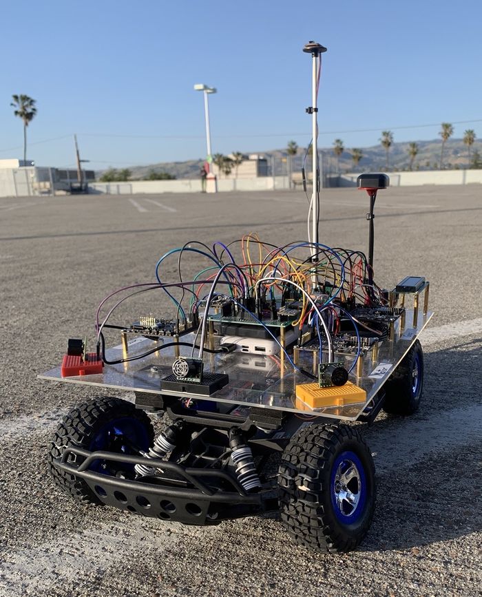
Team Zero's Self driving RC car, as the name states, is an autonomous vehicle designed to navigate to a given specified destination successfully, avoiding obstacles along its way. The car's infrastructure is built upon four key components: the Driver, Sensor-Bridge, Geo, and Motor nodes, which communicate internally via a CAN Bus and with the user via a mobile app. The vehicle continuously senses and processes all the information from these nodes to make decisions to ensure it stays on course and reaches its destination. It is built on a hobby-grade RC car chassis, modified with the necessary components and adjustments to fulfill its primary objectives of autonomous navigation and obstacle avoidance.
Introduction
The project was divided into N modules:
- Geographical Controller and LCD
- Motor Controller
- Sensor-Bridge Controller
- Driver Controller
- Mobile Application
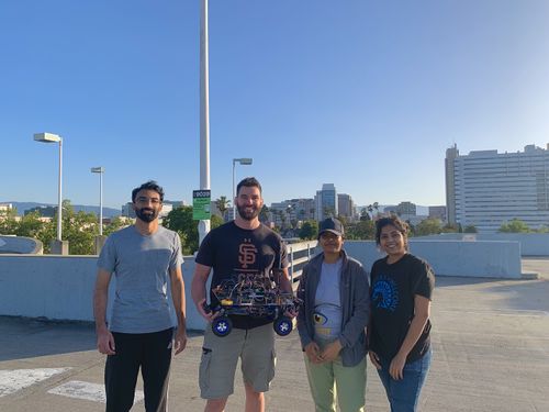
Team Members & Responsibilities
Gitlab Project Link - [1]
Cody Ourique [2]
- Geo controller
- Compass,GPS and LCD interfacing
- Hardware design, development and mounting
- LCD modules
- Unit Testing
Anusha Arunnandi [3]
- Sensor-Bridge controller
- Ultrasonic range finder and bluetooth interfacing
- Web application
- Unit Testing
Chaitanya Battula [4]
- Driver controller
- Motor controller
- RPM sensor, ESC, and servo motor interfacing
- Unit Testing
Rohit Duvvuru [5]
- Unit Testing
Schedule
| Week# | Start Date | End Date | Task | Status |
|---|---|---|---|---|
| 1 | 03/03/2024 | 03/09/2024 |
|
Completed |
| 2 | 03/10/2024 | 03/16/2024 |
|
Incomplete |
| 3 | 03/17/2024 | 03/23/2024 |
|
Incomplete |
| 4 | 03/24/2024 | 03/30/2024 |
|
Incomplete |
| 5 | 03/31/2024 | 04/06/2024 |
|
Incomplete |
| 6 | 04/07/2024 | 04/13/2024 |
|
Incomplete |
| 7 | 04/14/2024 | 04/20/2024 |
|
Incomplete |
| 8 | 04/21/2024 | 04/27/2024 |
|
Incomplete |
| 9 | 04/28/2024 | 05/04/2024 |
|
Incomplete |
| 10 | 05/05/2024 | 05/11/2024 |
|
Incomplete |
| 11 | 05/12/2024 | 05/18/2024 |
|
Incomplete |
| 12 | 05/19/2024 | 05/25/2024 |
|
Incomplete |
Parts List & Cost
| Item# | Part Desciption | Vendor | Qty | Cost |
|---|---|---|---|---|
| 1 | RC car | Traxxas [6] | 1 | $239.95 |
| 2 | RPM sensor | Traxxas [7] | 1 | $12.00 |
| 3 | GPS Breakout Board | Adafruit [8] | 1 | $54.95 |
| 4 | PCB prototype circuit board | A1 Cables N PCBs [9] | 1 | $8.57 |
| 5 | Plexiglass | Lesnlok [10] | 1 | $9.98 |
| 6 | Wireless bluetooth RF transceiver | HiLetgo [11] | 1 | $9.95 |
| 7 | Compass | Adafruit [12] | 1 | $5.95 |
| 8 | Ultrasonic range finder | Adafruit [13] | 4 | $114.00 |
| 8 | Potentiometer | Amazon [14] | 1 | $9.99 |
| 8 | 2 Pack 15000mAh power bank | Amazon [15] | 1 | $19.99 |
| 8 | GPS Antenna Mount | Honbay [16] | 2 | $7.29 |
| 8 | I2C Qwiic Cable Kit | Amazon [17] | 1 | $9.99 |
| 8 | Black Foam Padding | Amazon [18] | 1 | $11.99 |
| 8 | Traxxas 6537 Wire Retainers | Amazon [19] | 1 | $6.95 |
| 8 | USB Micro-B Breakout Board | Adafruit [20] | 1 | $4.88 |
| 8 | 24 awg Wire Solid Core | Amazon [21] | 1 | $14.99 |
| 8 | ELEGOO 6PCS 170 tie-Points Mini Breadboard | Amazon [22] | 1 | $6.98 |
| 8 | GPS Antenna | Amazon [23] | 1 | $10.99 |
| 8 | Standoffs | Amazon [24] | 1 | $22.96 |
| 8 | Breadboard Wires | Amazon [25] | 1 | $5.97 |
| 8 | 3/16 inch fiberglass rod | TAP plastics | 1 | $5.11 |
Prototype Circuit Board
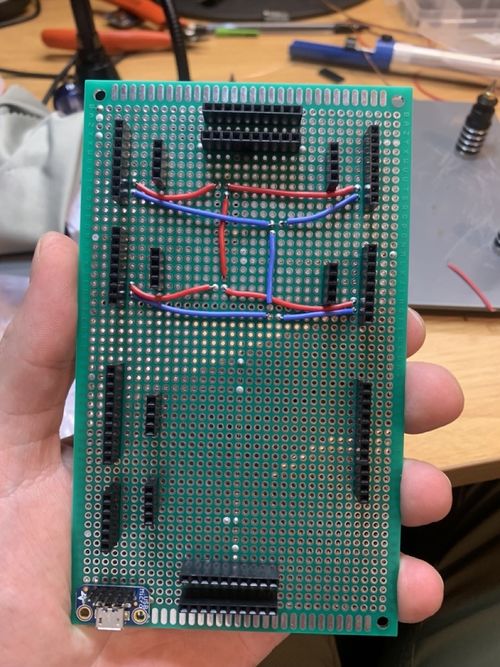
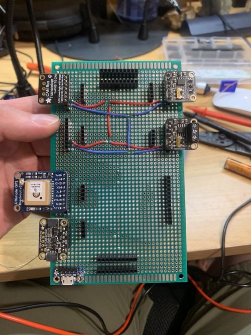
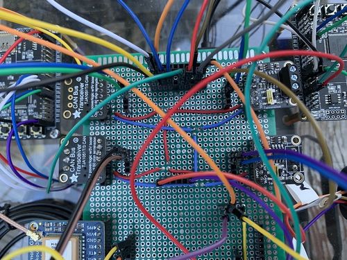
This prototype circuit board was carefully designed so that it could power all the microcontrollers, compass module, GPS module, bluetooth module, ultrasonic sensors and the LCD. In addition, the board has 4 slots for CAN tranceivers and an integrated CAN bus line. The board has a common ground line for all connected devices and has a total of 20 available sockets. Also, the board has 3.3V power and has 20 open sockets. Additionally, the board has 5V power with 4 available sockets delivered via micro USB.
CAN Communication
The microcontrollers communicate using the CAN bus. Each controller is sending or receiving CAN messages through periodic callback functions. All CAN bus messages are transmitted every 10Hz.
Geographical Controller CAN Messages:
- GEO_READINGS: The geo readings message responsibility is to send the heading, bearing and distance to destination information to the driver and sensor-bridge nodes. The driver node uses the geo readings to determine which direction it should go and when the vehicle should stop. In addition, the sensor-bridge needs the data to display it to the user on the mobile application.
- GEO_DATA_TO_DRIVER_AND_BRIDGE: This message's responsibility was to send current coordinates to the driver and sensor-bridge nodes so that the data could be properly displayed over the mobile application. The MIA threshold for this message is 100 and if this message goes into MIA its values will be set to 0.
- GEO_DEBUG_MESSAGE: The purpose of the debug message was to send a signal to the driver that the GPS has acquired a fix on the current location and another value to indicate the number of periodic callbacks needed to acquire the lock.
Sensor_Bridge Controller CAN Messages:
- SENSOR_ULTRA_SONIC
- SENSOR_BATTERY
- BRIDGE_DATA_TRANSFER
Motor Controller CAN Messages:
- MOTOR_READINGS
Driver Controller CAN Messages:
- DRIVER_HEARTBEAT
- MOTOR_CMD
Hardware Design
DBC File
VERSION ""

NS_ :
	BA_
	BA_DEF_
	BA_DEF_DEF_
	BA_DEF_DEF_REL_
	BA_DEF_REL_
	BA_DEF_SGTYPE_
	BA_REL_
	BA_SGTYPE_
	BO_TX_BU_
	BU_BO_REL_
	BU_EV_REL_
	BU_SG_REL_
	CAT_
	CAT_DEF_
	CM_
	ENVVAR_DATA_
	EV_DATA_
	FILTER
	NS_DESC_
	SGTYPE_
	SGTYPE_VAL_
	SG_MUL_VAL_
	SIGTYPE_VALTYPE_
	SIG_GROUP_
	SIG_TYPE_REF_
	SIG_VALTYPE_
	VAL_
	VAL_TABLE_

BS_:

BU_: DBG DRIVER MOTOR SENSOR_BRIDGE GEO

BO_ 100 DRIVER_HEARTBEAT: 1 DRIVER
 SG_ DRIVER_HEARTBEAT_cmd : 0|8@1+ (1,0) [0|0] "" SENSOR_BRIDGE,MOTOR

BO_ 101 MOTOR_CMD: 1 DRIVER
 SG_ MOTOR_CMD_steer : 0|4@1- (1,0) [-5|5] "steering direction" MOTOR
 SG_ MOTOR_CMD_drive : 4|4@1+ (0.1,-5) [-5|5] "kph" MOTOR

BO_ 102 MOTOR_READINGS: 4 MOTOR
 SG_ MOTOR_READINGS_steer_degrees : 0|4@1- (1,0) [-5|5] "steer direction" DRIVER
 SG_ MOTOR_READINGS_speed : 4|4@1+ (0.1,-5) [-5|5] "kph" DRIVER

BO_ 200 SENSOR_ULTRA_SONIC: 8 SENSOR_BRIDGE
 SG_ SENSOR_ULTRA_SONIC_left : 0|10@1+ (1,0) [0|500] "cm" DRIVER
 SG_ SENSOR_ULTRA_SONIC_right : 10|10@1+ (1,0) [0|500] "cm" DRIVER
 SG_ SENSOR_ULTRA_SONIC_middle : 20|10@1+ (1,0) [0|500] "cm" DRIVER
 SG_ SENSOR_ULTRA_SONIC_back : 30|10@1+ (1,0) [0|500] "cm" DRIVER

BO_ 202 SENSOR_BATTERY: 1 SENSOR_BRIDGE
 SG_ SENSOR_BATTERY_voltage : 0|8@1+ (1,0) [0|0] "V" DRIVER

BO_ 300 BRIDGE_DATA_TRANSFER: 8 SENSOR_BRIDGE
 SG_ GPS_DESTINATION_send_latitude : 0|32@1+ (0.000001,0) [0|0] "Degrees" GEO
 SG_ GPS_DESTINATION_send_longitude : 32|32@1+ (0.000001,0) [0|0] "Degrees" GEO

BO_ 301 GEO_READINGS: 8 GEO
 SG_ GEO_READINGS_COMPASS_HEADING : 0|12@1+ (1,0) [0|359] "Degrees" DRIVER, SENSOR_BRIDGE
 SG_ GEO_READINGS_COMPASS_BEARING : 12|12@1+ (1,0) [0|359] "Degrees" DRIVER, SENSOR_BRIDGE
 SG_ GEO_READINGS_DISTANCE_TO_DESTINATION : 24|24@1+ (1,0) [0|0] "Meters" DRIVER, SENSOR_BRIDGE

BO_ 302 GEO_DATA_TO_DRIVER_AND_BRIDGE: 8 GEO
	SG_ GEO_DATA_TO_DRIVER_AND_BRIDGE_latitude : 0|32@1+ (0.000001,0) [0|0] "Degrees" DRIVER, SENSOR_BRIDGE
	SG_ GEO_DATA_TO_DRIVER_AND_BRIDGE_longitude : 32|32@1+ (0.000001,0) [0|0] "Degrees" DRIVER, SENSOR_BRIDGE

BO_ 304 GEO_DEBUG_MESSAGE: 2 GEO
	SG_ GEO_DEBUG_MESSAGE_LOCK : 0|8@1+ (1,0) [0|0] "Boolean" DRIVER
	SG_ GEO_DEBUG_MESSAGE_LOCK_TIME : 8|8@1+ (0.1,0) [0|0] "Seconds" DRIVER

CM_ BU_ GEO "The gps contoller";
CM_ BU_ SENSOR_BRIDGE "The bridge controller";
CM_ BU_ DRIVER "The driver controller driving the car";
CM_ BU_ MOTOR "The motor controller of the car";
CM_ BO_ 100 "Sync message used to synchronize the controllers";
CM_ SG_ 100 DRIVER_HEARTBEAT_cmd "Heartbeat command from the driver";

BA_DEF_ "BusType" STRING ;
BA_DEF_ BO_ "GenMsgCycleTime" INT 0 0;
BA_DEF_ SG_ "FieldType" STRING ;

BA_DEF_DEF_ "BusType" "CAN";
BA_DEF_DEF_ "FieldType" "";
BA_DEF_DEF_ "GenMsgCycleTime" 0;

BA_ "GenMsgCycleTime" BO_ 100 1000;
BA_ "GenMsgCycleTime" BO_ 200 50;
BA_ "FieldType" SG_ 100 DRIVER_HEARTBEAT_cmd "DRIVER_HEARTBEAT_cmd";

VAL_ 100 DRIVER_HEARTBEAT_cmd 2 "DRIVER_HEARTBEAT_cmd_REBOOT" 1 "DRIVER_HEARTBEAT_cmd_SYNC" 0 "DRIVER_HEARTBEAT_cmd_NOOP" ;
Sensor ECU
<Picture and link to Gitlab>
Hardware Design
Software Design
<List the code modules that are being called periodically.>
Technical Challenges
< List of problems and their detailed resolutions>
Motor ECU
Motor - https://gitlab.com/Ouriquco/cmpe_243_team_zero/-/tree/NodeMotor/projects/MotorNode?ref_type=heads
Motor node receives
Hardware Design
The motor is controlled using various PWM signals to move forward, backward, or steer in different directions. The SJ2C board has specific pins designated for PWM signals. Two such pins, P2.0 and P2.1, are dedicated to controlling the motor's speed and servo. The SJ2 board, with its excellent I/O capabilities, allows for precise modulation of output signals to accurately control both the DC and servo motors.
Software Design
<List the code modules that are being called periodically.>
Technical Challenges
< List of problems and their detailed resolutions>
Geographical Controller & LCD
Gitlab Geographical Controller Source Code - [26]
The geographical controllers responsibilities are to ensure that the driver and sensor-bridge controllers receive the most accurate data related to bearing, heading, destination and current coordinates. This information provides the driver controller with the data they need to make logical decisions related to the movement of the vehicle. Also, the information is needed to tell the user why the vehicle may be changing direction. A geographical controller is necessary in any application where location is integrated into the system.
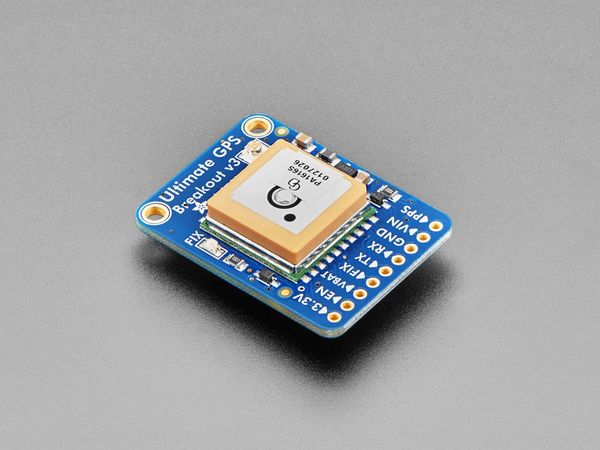
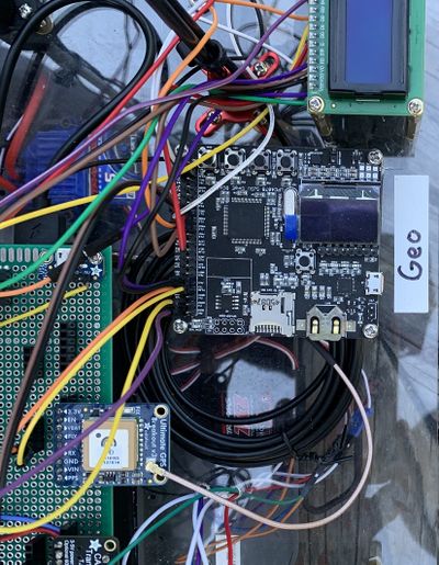
The GPS module has a built in antenna and acquires latitude and longitude in GPGGA format every 10Hz. This module is rated between 3.3V and 5V. In our project we powered this module using 3.3V by integrating it on the prototype board. In addition, we used an external antenna to increase signal strength.
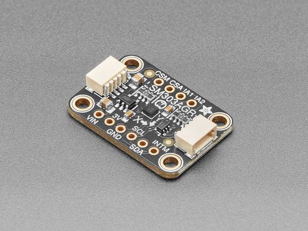
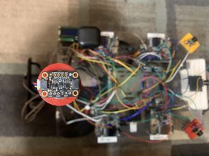
The compass module is a triple axis accelerometer/magnetometer. The accelerometer can tell you which direction is down towards the Earth (by measuring gravity). The magnetometer can sense where the strongest magnetic force is coming from, generally used to detect magnetic north.
Hardware Design
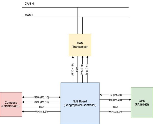
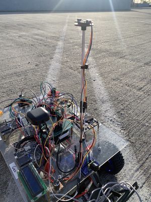
The GPS and Compass are both powered by 3.3.V through the prototype board. The GPS uses UART to send and receive GPGGA data. The Compass sends and receives data over I2C. The microcontroller processes this data periodically, every 10 Hz, and sends the data to the CAN transceiver which is connected to the CAN bus line. The compass experienced soft iron and hard iron distortions. Therefore, it was necessary to mount the compass as far away from the car as possible. This goal was accomplished by mounting it approximately 1 ft above the vehicle. In addition, it was difficult for the GPS to acquire a signal fix. To mitigate this issue we mounted an external compass approximately 6 inches above the vehicle.
Software Design
<List the code modules that are being called periodically.> GPS Module This module extracts the NMEA data every 10Hz. The data is then stored in a structure that holds the longitude and latitude values. After the data is stored, the structure is returned and used by the geo code module.
Geo controller modules:
- 1. GPS
- 2. Compass
- 3. Waypoints
- 4. Geo logic
- 5. CAN handler
- 6. Line buffer
- 1. GPS
gps.h
typedef struct {
  float latitude;
  float longitude;
} gps_coordinates_t;

void gps__init(void);
void gps__run_once(void);

gps_coordinates_t gps__get_coordinates(void);

}
- 2. Compass
compass.h
typedef struct {
  float x;
  float y;
  float z;
} mag_data_t;

typedef struct {
  double latitude;
  double longitude;
} Coordinates;

void compass_init();
float get_current_compass_heading();
double calculate_bearing(Coordinates point1, Coordinates point2);
double calculate_distance(Coordinates point1, Coordinates point2);

}
- 3. Waypoints
waypoints.h
gps_coordinates_t waypoints__find_next_waypoint(gps_coordinates_t origin, gps_coordinates_t destination);
double waypoints__calculate_distance(gps_coordinates_t point1, gps_coordinates_t point2);
double waypoints__update_current_bearing(gps_coordinates_t point1, gps_coordinates_t point2);
- 4. Geo logic
geo_logic.h
- 5. CAN handler
can_handlers.h
- 6. Line Buffer
line_buffer.h
Technical Challenges
< List of problems and their detailed resolutions>
Communication Bridge Controller
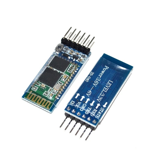
The HC-05 Bluetooth module is a widely used and versatile wireless communication module that enables Bluetooth connectivity using its Serial Port Protocol. Key Features HC-05 Bluetooth Module:
Bluetooth Standard:
The HC-05 Bluetooth module operates on Bluetooth version 2.0 + EDR (Enhanced Data Rate), supporting reliable and efficient wireless communication.
Operating Modes:
The module can operate in both Master and Slave modes. In Slave mode, it can pair with other Bluetooth devices, while in Master mode, it can initiate connections.
Communication Range:
The HC-05 is classified as a Class 2 Bluetooth device, providing a communication range of approximately 10 meters (33 feet). This makes it suitable for short to medium-range applications.
Serial Communication:
It communicates with other devices using a serial communication interface, making it compatible with microcontrollers like Arduino. The module typically supports standard baud rates like 9600 bps.
AT Command Configuration:
The HC-05 Bluetooth module can be configured using AT commands, allowing users to customize various parameters such as the device name, pairing code, and operating mode.
Voltage Compatibility:
The module operates within a voltage range of 3.6V to 6V, making it compatible with a variety of power sources.
Security Features:
The HC-05 supports basic security features, including the ability to set a PIN code for pairing and configuring security modes.
LED Indicator:
Many HC-05 modules have an onboard LED indicator that provides visual feedback on the pairing status and communication activity.
Hardware Design
Connected Vcc, GND, Tx and Rx pins. It requires 3.6-6V for functioning. The Tx and Rx pins are used to transmit and recieve the data to and from the application.
Software Design
o begin using serial transmission, you first need to pair the module to your device. During the pairing process, the password request encountered should be expecting one of the default passwords "1234" or "0000". You can change this password using one of the AT commands. We are calling the bluetooth the recieve and transmit functions periodically to send and recieve data in 10Hz periodic callbacks.
Technical Challenges
When we were powering to 3.3V, the LED on the bluetooth was blinking but it was not listing on the mobile phone when we had to connect it. After careful reading of the datasheet, we figured out that we have to power up with 3.6-6V.
Master Module
<Picture and link to Gitlab>
Hardware Design
Software Design
<List the code modules that are being called periodically.>
Technical Challenges
< List of problems and their detailed resolutions>
Mobile Application
MIT App Inventor 2 is a free, open-source web application for creating basic Android mobile applications without needing to code in Java or Kotlin. Instead, it uses block-based coding and a graphical user interface (GUI) similar to the Scratch programming language. Users can drag and drop blocks to design the user interface (UI) and employ functional blocks to develop logic, functions, and control flow.
Originally developed by Google and released in 2010, MIT App Inventor for Android was created by a team led by Hal Abelson and Mark Friedman. In the latter half of 2011, Google released the source code, ceased its server operations, and funded the establishment of The MIT Center for Mobile Learning. This center, led by App Inventor creator Hal Abelson and MIT professors Eric Klopfer and Mitchel Resnick, launched the MIT version of App Inventor in March 2012.
The platform includes the MIT AI Companion app, a mobile application that allows users to download a server-cached version of their app in development. This feature facilitates easy and convenient testing of intermediate functions and bug fixes by enabling real-time observation of changes. Once development is complete, users can build and download a ".apk" file, an installable file for the Android OS that allows them to test their app as a standalone application.
The web app features two key sections for mobile app development: the Designer page and the Blocks page.
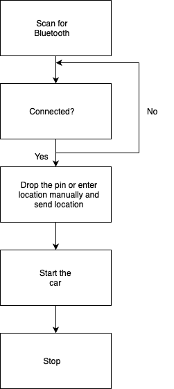
Flow
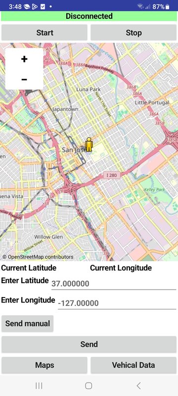
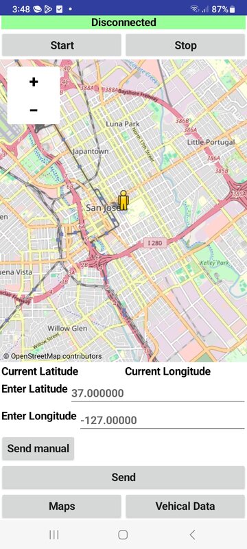
User Interface
Connects and disconnects the bluetooth and has start and stop buttons. The destination can be given by dropping the pin on the map. It can also be entered manually.
Connects and disconnects the bluetooth. This screen gives the current latitude, longitude, distance to destination, speed of the car and all other details.
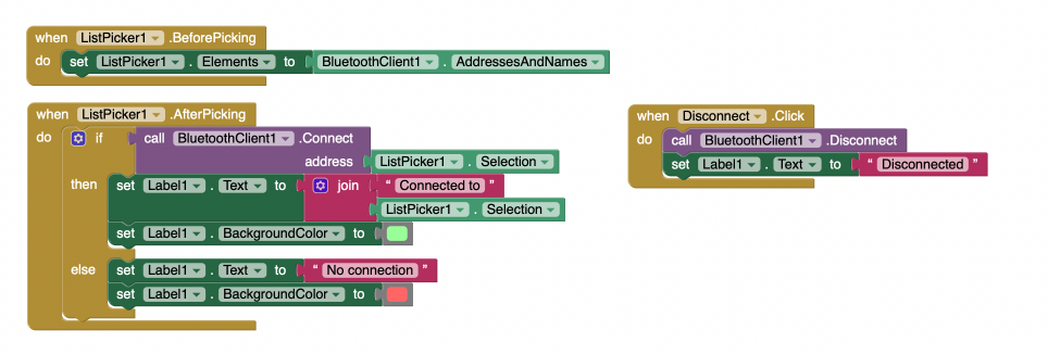
Bluetooth Block
The App uses the bluetooth client block to establish a connection with the HC-05 bluetooth module onboard the car. It is necessary to establish connection and connect to a bluetooth pair to send and receive messages.
Testing and Downloading
MIT App inventor projects can be accessed for testing on the MIT AI companion app or built into a downloadable APK file. It can also be exported as a file to be later imported. The file extension for an app inventor project is “.aia”.
Conclusion
<Organized summary of the project>
<What did you learn?>
Project Video
Project Source Code
Advise for Future Students
<Bullet points and discussion>
Acknowledgement
=== References ===
