Difference between revisions of "S23: Meh-sla Automotive"
| Line 1: | Line 1: | ||
== Project Title == | == Project Title == | ||
¯\_(ツ)_/¯ Meh-Sla Automotive ¯\_(ツ)_/¯ | ¯\_(ツ)_/¯ Meh-Sla Automotive ¯\_(ツ)_/¯ | ||
| − | + | ||
<BR/> | <BR/> | ||
Revision as of 16:49, 22 May 2023
Contents
Project Title
¯\_(ツ)_/¯ Meh-Sla Automotive ¯\_(ツ)_/¯
Abstract
Through our experience we knew that we wouldn't be the Worst-Sla. We say that we are Meh-Sla even though we know we are the Best-Sla.
Introduction
The project was divided into 5 modules:
- Sensor
- Motor
- Geological
- Driver
- Android
Team Members & Responsibilities
<Team Picture>
Gitlab Project Link - [1]
<Provide ECU names and members responsible>
- Tony Zunino
- Team Lead
- Motor Board
- Sindhuja Ravi
- Geo Board
- Android App
- Stephen Oneto
- Driver and LCD Board
- Karthigai Amutha Ezhilarasu
- Sensor Board
- Geo Board
- Phil Bloxom
- Hardware Setup
- Software Testing
Schedule
| Week # | Start Date | End Date | Task | Status |
|---|---|---|---|---|
| 1 | 2/12/2023 | 2/18/2023 |
|
|
| 2 | 2/19/2023 | 2/25/2023 |
|
|
| 3 | 26/2/2023 | 3/4/2023 |
|
|
| 4 | 3/5/2023 | 3/11/2023 |
|
|
| 5 | 3/12/2023 | 3/18/2023 |
|
|
| 6 | 3/19/2023 | 3/25/2023 |
|
|
| 7 | 3/26/2023 | 4/1/2023 |
|
|
| 8 | 4/2/2023 | 4/8/2023 |
|
|
| 9 | 4/9/2023 | 4/15/2023 |
|
|
| 10 | 4/16/2023 | 4/22/2023 |
|
|
| 11 | 4/23/2023 | 4/29/2023 |
|
|
| 12 | 4/30/2023 | 5/6/2023 |
|
|
| 13 | 5/7/2023 | 5/13/2023 |
|
|
| 14 | 5/14/2023 | 5/19/2023 |
|
|
| 15 | 5/20/2023 | 5/26/2023 |
|
|
Parts List & Cost
| Item# | Part Desciption | Vendor | Qty | Cost |
|---|---|---|---|---|
| 1 | RC Car | Traxxas | 1 | $250.00 |
| 2 | CAN Transceivers (SN65HVD230) | Waveshare [2] | 4 | Free Samples |
| 3 | RC Car RPM | Traxxas [3] | 1 | 8.23 |
| 4 | Adafruit Bluetooth BLE Friend | Adafruit [4] | 1 | 17.5 |
| 5 | GPS Module | [5] | 1 | |
| 6 | Compass Module | [6] | 1 | |
| 7 | LCD Screen | [7] | 1 |
System Hardware Design
Block Diagram
CAN Communication
<Talk about your message IDs or communication strategy, such as periodic transmission, MIA management etc.>
Hardware Design
<Show your CAN bus hardware design>
DBC File
VERSION ""

NS_ :
	BA_
	BA_DEF_
	BA_DEF_DEF_
	BA_DEF_DEF_REL_
	BA_DEF_REL_
	BA_DEF_SGTYPE_
	BA_REL_
	BA_SGTYPE_
	BO_TX_BU_
	BU_BO_REL_
	BU_EV_REL_
	BU_SG_REL_
	CAT_
	CAT_DEF_
	CM_
	ENVVAR_DATA_
	EV_DATA_
	FILTER
	NS_DESC_
	SGTYPE_
	SGTYPE_VAL_
	SG_MUL_VAL_
	SIGTYPE_VALTYPE_
	SIG_GROUP_
	SIG_TYPE_REF_
	SIG_VALTYPE_
	VAL_
	VAL_TABLE_

BS_:

BU_: DBG DRIVER MOTOR SENSOR GEO

BO_ 100 DRIVER_HEARTBEAT: 1 DRIVER
 SG_ DRIVER_HEARTBEAT_cmd : 0|8@1+ (1,0) [0|0] "" SENSOR,MOTOR

BO_ 101 MOTOR_SPEED: 1 DRIVER
 SG_ DC_MOTOR_DRIVE_SPEED_sig : 0|8@1+ (0.1,-10) [-10|10] "kph" MOTOR

BO_ 102 MOTOR_ANGLE: 1 DRIVER
 SG_ SERVO_STEER_ANGLE_sig : 0|8@1+ (1,-45) [-45|45] "degrees" MOTOR


BO_ 200 SENSOR_SONARS: 4 SENSOR
 SG_ SENSOR_SONARS_left : 0|8@1+ (1,0) [0|158] "inch" DRIVER
 SG_ SENSOR_SONARS_right : 8|8@1+ (1,0) [0|158] "inch" DRIVER
 SG_ SENSOR_SONARS_front : 16|8@1+ (1,0) [0|158] "inch" DRIVER
 SG_ SENSOR_SONARS_rear : 24|8@1+ (1,0) [0|158] "inch" DRIVER

BO_ 202 GPS_DESTINATION_LOCATION: 8 SENSOR
 SG_ GPS_DEST_LAT_SCALED_1000000 : 0|32@1- (1,0) [0|0] "Degrees" GEO
 SG_ GPS_DEST_LONG_SCALED_1000000 : 32|32@1- (1,0) [0|0] "Degrees" GEO

BO_ 203 GEO_STATUS: 8 GEO
 SG_ GEO_STATUS_COMPASS_HEADING : 0|12@1+ (0.1,0) [0|359.9] "Degrees" DRIVER,SENSOR
 SG_ GEO_STATUS_COMPASS_BEARING: 12|12@1+ (0.1,0) [0|359.9] "Degrees" DRIVER,SENSOR
 SG_ GEO_STATUS_DISTANCE_TO_DESTINATION : 24|16@1+ (0.01,0) [0|0] "Meters" DRIVER,SENSOR

BO_ 204 GPS_CURRENT_INFO: 8 GEO
 SG_ GPS_CURRENT_LAT_SCALED_1000000 : 0|32@1- (1,0) [0|0] "degrees" DRIVER,SENSOR,MOTOR
 SG_ GPS_CURRENT_LONG_SCALED_1000000 : 32|32@1- (1,0) [0|0] "degrees" DRIVER,SENSOR,MOTOR

BO_ 205 GPS_CURRENT_DESTINATIONS_DATA: 8 GEO
 SG_ CURRENT_DEST_LAT_SCALED_1000000 : 0|32@1- (1,0) [0|0] "Degrees" DRIVER
 SG_ CURRENT_DEST_LONG_SCALED_1000000 : 32|32@1- (1,0) [0|0] "Degrees" DRIVER

BO_ 206 BRIDGE_APP_COMMANDS: 1 SENSOR
 SG_ APP_COMMAND : 0|2@1+ (1,0) [0|0] "" GEO,DRIVER

BO_ 300 MOTOR_STATUS: 3 MOTOR
 SG_ MOTOR_STATUS_wheel_error : 0|1@1+ (1,0) [0|0] "" DRIVER,IO
 SG_ MOTOR_STATUS_speed_kph : 8|16@1+ (0.001,0) [0|0] "kph" DRIVER,IO

BO_ 401 MOTOR_DEBUG: 1 MOTOR
 SG_ IO_DEBUG_test_unsigned : 0|8@1+ (1,0) [0|256] "sec" DBG

CM_ BU_ DBG "The debugging node for testing dbc with the car";
CM_ BU_ DRIVER "The driver controller driving the car";
CM_ BU_ MOTOR "The motor controller of the car";
CM_ BU_ SENSOR "The sensor controller of the car";
CM_ BU_ GEO "The geological Controller of the car";
CM_ BO_ 100 "Sync message used to synchronize the controllers";
CM_ SG_ 100 DRIVER_HEARTBEAT_cmd "Heartbeat command from the driver";
CM_ SG_ 101 DC_MOTOR_DRIVE_SPEED_sig "The speed in kph to set the motor speed. TODO: choose kph/mph";
CM_ SG_ 102 SERVO_STEER_ANGLE_sig "The direction in degrees to set the RC car servo direction.";

BA_DEF_ "BusType" STRING ;
BA_DEF_ BO_ "GenMsgCycleTime" INT 0 0;
BA_DEF_ SG_ "FieldType" STRING ;

BA_DEF_DEF_ "BusType" "CAN";
BA_DEF_DEF_ "FieldType" "";
BA_DEF_DEF_ "GenMsgCycleTime" 0;

BA_ "GenMsgCycleTime" BO_ 100 1000;
BA_ "GenMsgCycleTime" BO_ 200 50;
BA_ "FieldType" SG_ 100 DRIVER_HEARTBEAT_cmd "DRIVER_HEARTBEAT_cmd";

VAL_ 100 DRIVER_HEARTBEAT_cmd 2 "DRIVER_HEARTBEAT_cmd_REBOOT" 1 "DRIVER_HEARTBEAT_cmd_SYNC" 0 "DRIVER_HEARTBEAT_cmd_NOOP" ;
Sensor and Bridge Controller
Hardware Design
Ultrasonic Sensors
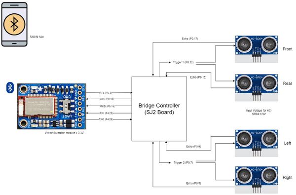
We used HC-SR04 ultrasonic sensors for obstacle detection. It could provide a range from 2 cm to 400 cm non-contact measurement. The ranging accuracy is approximately 3mm and the effectual angle is less than 15°. It needs to be powered by a 5V power supply. We are using 4 HC-SR04 sensors in the RC car(front, rear, left, and right).
HC-SR04 specifications
- Operating voltage: +5V
- Theoretical Measuring Distance: 2cm to 450cm
- Practical Measuring Distance: 2cm to 80cm
- Accuracy: 3mm
- Measuring angle covered: <15°
- Operating Current: <15mA
- Operating Frequency: 40Hz
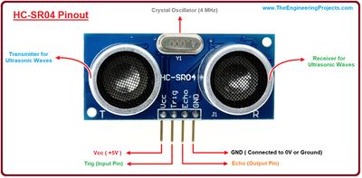
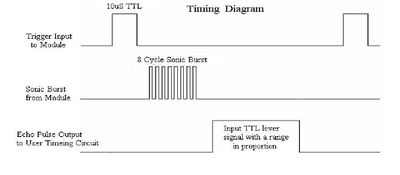
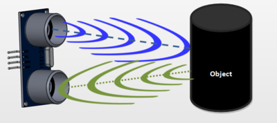
The pinout and the timing diagram of the HC-SR04 sensor are shown in the following figures. The module includes an ultrasonic transmitter, a receiver, and a control circuit. The basic principle of work: When the trigger pin is set HIGH for at least 10us, the module automatically sends a 40 kHz ultrasonic wave from the Ultrasonic transmitter. This wave travels in the air and when it gets obstructed by any material it gets reflected back toward the sensor. This reflected wave is observed by the Ultrasonic receiver module. Once the wave is returned the Echo pin goes high for a particular amount of time which will be equal to the time taken for the wave to return back to the sensor. The amount of time during which the Echo pin stays high is measured by the SJ2 board as it gives the information about the time taken for the wave to return back to the Sensor. Using this information the distance is measured as explained in the above heading. From that duration, the distance at which the object is present can be measured using the formula, Distance = Speed × Time.
Bluetooth Module
For the communication between the mobile and the RC Car, we are using Adafruit Bluefruit LE UART Friend - BLE module. This module communicates with the SJ2 board through UART at a baud rate of 9600. It also has the capability of working in two modes (data mode and command mode). We can toggle between the two modes using the MOD pin through a GPIO signal or manually using the onboard switch. It supports AT command set, which can be used to control the device's behavior. In data mode, the data written to the UART in the form of a string will be sent through Bluetooth.
Adafruit Bluefruit specifications
- ARM Cortex M0 core running at 16MHz
- 256KB flash memory
- 32KB SRAM
- Transport: UART @ 9600 baud with HW flow control (CTS+RTS required)
- 5V-safe inputs
- On-board 3.3V voltage regulation
- Bootloader with support for safe OTA firmware updates
- Easy AT command set to get up and running quickly
Software Design
We read about the signal interference of adjacent sensors from many of the past projects. So we decided to avoid that interference by triggering two non-adjacent sensors at a time. The FRONT_REAR sensor pair is triggered first. Once both of the sensors compute the distance from the obstacle, then the next pair, RIGHT_LEFT is triggered. For the ultrasonic sensors, we used a separate task instead of the periodic callbacks since this task sleeps on a semaphore which might affect the other functions in the periodic callback function.
Ultrasonic Sensors
SONAR task
void sonar_task(void *p) {
 sonar__init();
 front_rear_echo_received = xSemaphoreCreateBinary();
 left_right_echo_received = xSemaphoreCreateBinary();
 lpc_peripheral__enable_interrupt(LPC_PERIPHERAL__GPIO, sonar__interrupt_dispatcher, "sonar_timing_handler");
 NVIC_EnableIRQ(GPIO_IRQn);
 while (1) {
   sonar__send_trigger_for_10us(FRONT_REAR);
   if (xSemaphoreTake(front_rear_echo_received, 1000)) {
     sonar_pair_info[0].distance_from_obstacle_sonar1 = sonar__compute_obstacle_distance_single_sensor(FRONT_SONAR);
     sonar_pair_info[0].distance_from_obstacle_sonar2 = sonar__compute_obstacle_distance_single_sensor(REAR_SONAR);
   }
   sonar__send_trigger_for_10us(LEFT_RIGHT);
   if (xSemaphoreTake(left_right_echo_received, 1000)) {
     sonar_pair_info[1].distance_from_obstacle_sonar1 = sonar__compute_obstacle_distance_single_sensor(LEFT_SONAR);
     sonar_pair_info[1].distance_from_obstacle_sonar2 = sonar__compute_obstacle_distance_single_sensor(RIGHT_SONAR);
   }
   sonar__averaging_sensor_values();
   vTaskDelay(10);
 }
}
Technical Challenges
< List of problems and their detailed resolutions>
Motor ECU
Hardware Design
PCB Design
Phil to talk about PCB design and choices for layout
Battery Management
Phil to talk about the peripheral battery and main motor battery separation
Software Design
<List the code modules that are being called periodically.>
RPM Module
Tony will write about how the RPM module was implemented using triggers.
void sonar_task(void *p) {
  Test
}
Motor Module
Tony will write about the motor and how forward/reverse works
static float test_task(float lol) {
  Just wanted to see if this is cool;
}
Steering Module
Tony will write about the motor and how forward/reverse works
static float test_task(float lol) {
  Preet is cool;
  if(Phil_is_reading) Phil is cooler;
  else Tony is the coolest
}
Technical Challenges
< List of problems and their detailed resolutions>
Geological Controller
<Picture of Compass>
<Picture of GPS>
<Picture of Block Diagram>
Hardware Design
Software Design
<List the code modules that are being called periodically.>
Technical Challenges
< List of problems and their detailed resolutions>
Communication Bridge Controller
<Picture of LCD> <Picture of Block Diagram>
Hardware Design
Software Design
<List the code modules that are being called periodically.>
Technical Challenges
< List of problems and their detailed resolutions>
Driver/LCD Controller
<Picture of LCD> <Picture of Block Diagram>
Hardware Design
Software Design
<List the code modules that are being called periodically.>
Technical Challenges
< List of problems and their detailed resolutions>
Master Module
<Picture and link to Gitlab>
Hardware Design
Software Design
<List the code modules that are being called periodically.>
Technical Challenges
< List of problems and their detailed resolutions>
Mobile Application
<Picture and link to Gitlab>
Hardware Design
Software Design
<List the code modules that are being called periodically.>
Technical Challenges
< List of problems and their detailed resolutions>
Conclusion
<Organized summary of the project>
<What did you learn?>
Project Video
Project Source Code
Advise for Future Students
<Bullet points and discussion>
Acknowledgement
=== References ===
