Difference between revisions of "F22: DDRTOS"
(→Design & Implementation) |
(→Parts List & Cost) |
||
| (49 intermediate revisions by the same user not shown) | |||
| Line 1: | Line 1: | ||
| − | |||
| − | |||
| − | |||
| − | |||
| − | |||
| − | |||
| − | |||
| − | |||
| − | |||
| − | |||
| − | |||
== Abstract == | == Abstract == | ||
| + | *[https://www.youtube.com/watch?v=SimXCBoI7Hg Demo Video (YouTube)] | ||
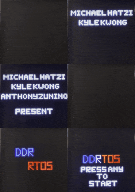
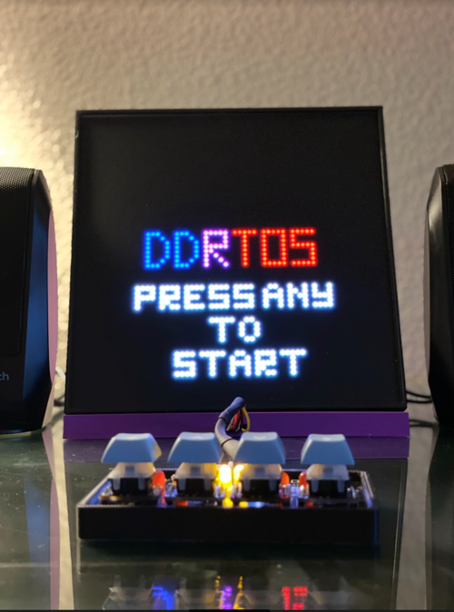
| + | [[File:DDRTOS_Title_sequence.gif]] | ||
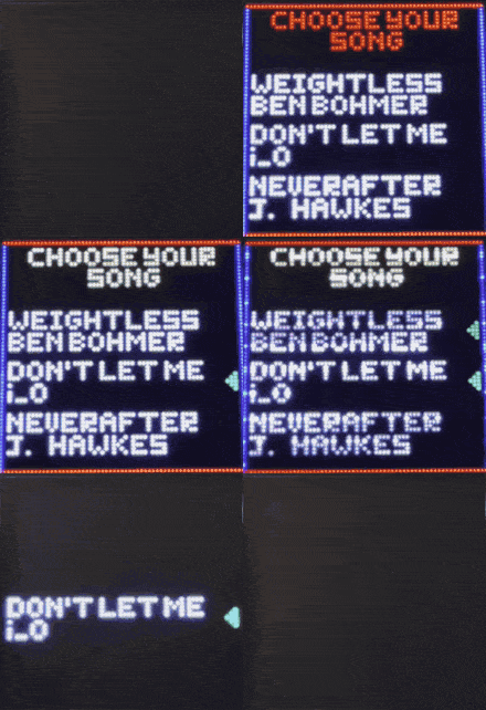
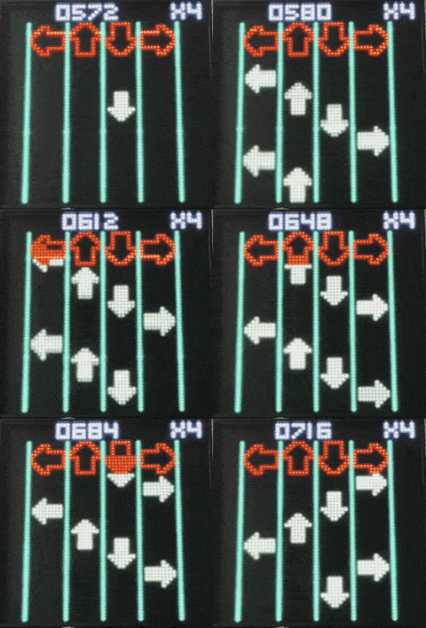
| + | [[File:Song_select_demo.gif]] | ||
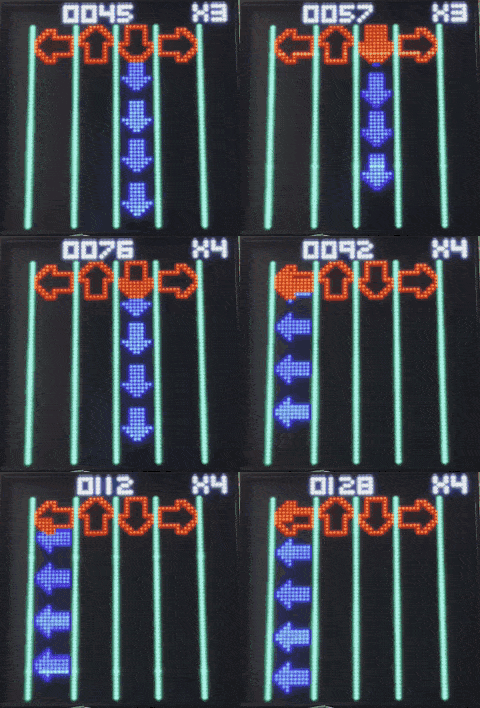
| + | [[File:Weightless_demo.gif]] | ||
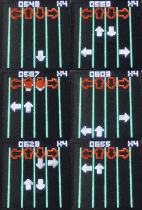
| + | [[File:Neverafter_demo.gif]] | ||
| + | [[File:Don%27t_Let_Me_Go_To_Sleep_demo.gif]] | ||
| + | |||
| + | Note: The frame rate is low because of the wiki upload limit | ||
| + | |||
| + | [[File:DDRTOS.png|500px|middle]] | ||
| + | |||
Rhythm games have been popular for years and date back to the 1970’s, but hit its stride in 1997 when one of the most notable and popular games released - Dance Dance Revolution (DDR). The main point of a rhythm game is to use music and challenge a player’s ability to stay on beat and typically press a button to the beat of the song. Our project is based and dedicated to DDR, as we all share a passion for music and video games. DDR is played with four arrows for each direction up, down, left, and right that need to be hit at the time of a beat in order to score and increase the multiplier. There are several aspects that are taken from other games like Guitar Hero and Friday Night Funkin’ (sound effects, multiplier, and artwork) that have also become a part of the project. Our project name, DDRTOS, is a combination of the game DDR and RTOS which runs the project. | Rhythm games have been popular for years and date back to the 1970’s, but hit its stride in 1997 when one of the most notable and popular games released - Dance Dance Revolution (DDR). The main point of a rhythm game is to use music and challenge a player’s ability to stay on beat and typically press a button to the beat of the song. Our project is based and dedicated to DDR, as we all share a passion for music and video games. DDR is played with four arrows for each direction up, down, left, and right that need to be hit at the time of a beat in order to score and increase the multiplier. There are several aspects that are taken from other games like Guitar Hero and Friday Night Funkin’ (sound effects, multiplier, and artwork) that have also become a part of the project. Our project name, DDRTOS, is a combination of the game DDR and RTOS which runs the project. | ||
== Objectives & Introduction == | == Objectives & Introduction == | ||
| − | + | === Objective=== | |
| + | * Create a DDR-like game on RTOS based system, hence the name DDRTOS | ||
| + | * Responsive button press | ||
| + | * Good Audio | ||
| + | * Good visual and audible response when hitting notes at the right time | ||
| + | |||
| + | === Game Introduction=== | ||
| + | * After the title sequence, you'll be prompted to press any key to start. | ||
| + | * After you press any key, you'll be brought to the song selection screen. | ||
| + | ** Press up or down to select song. | ||
| + | ** Press right to confirm you choice, and the game starts. | ||
| + | * The arrows are mapped to the beat, so you should aim to hit the button when the static red arrow is fully lit up. | ||
== Team Members & Responsibilities == | == Team Members & Responsibilities == | ||
[[File:MichaelHatzi.PNG|200px|middle]] | [[File:MichaelHatzi.PNG|200px|middle]] | ||
| − | * Michael Hatzikokolakis | + | * Michael Hatzikokolakis '''''[https://gitlab.com/mikehatzi8 Gitlab]''''' |
** Core gameplay development | ** Core gameplay development | ||
** Beatmap development | ** Beatmap development | ||
[[File:Kyle_Kwong.jpg|200px|middle]] | [[File:Kyle_Kwong.jpg|200px|middle]] | ||
| − | * Kyle Kwong | + | * Kyle Kwong '''''[https://gitlab.com/shiuyuen.kwong Gitlab]''''' |
** MP3 module driver development | ** MP3 module driver development | ||
** Audio system research and design | ** Audio system research and design | ||
** Ensure coding standards | ** Ensure coding standards | ||
** Assist on all parts of the project | ** Assist on all parts of the project | ||
| + | ** Wiki Manager | ||
[[File:Anthony_Zunino.png|200px|middle]] | [[File:Anthony_Zunino.png|200px|middle]] | ||
| − | * Anthony Zunino | + | * Anthony Zunino '''''[https://gitlab.com/zunino.anthony Gitlab]''''' |
** Enclosure Design | ** Enclosure Design | ||
** PCB Design | ** PCB Design | ||
| Line 206: | Line 218: | ||
! scope="row"| 3 | ! scope="row"| 3 | ||
| PCB | | PCB | ||
| − | | | + | | PCBWay [https://www.pcbway.com/] |
| 1 | | 1 | ||
| − | | $ | + | | $15.00 |
|- | |- | ||
! scope="row"| 4 | ! scope="row"| 4 | ||
| Line 232: | Line 244: | ||
| Adafruit [https://www.adafruit.com/product/4203?gclid=Cj0KCQiAqOucBhDrARIsAPCQL1akGqUcuxVrKoftjA3Vy2M-8zE51BbGOOx7V5AtSlwFwQsb9_0-KbYaAlygEALw_wcB] | | Adafruit [https://www.adafruit.com/product/4203?gclid=Cj0KCQiAqOucBhDrARIsAPCQL1akGqUcuxVrKoftjA3Vy2M-8zE51BbGOOx7V5AtSlwFwQsb9_0-KbYaAlygEALw_wcB] | ||
| 8 | | 8 | ||
| − | | $ | + | | $0.50 |
|- | |- | ||
! scope="row"| 8 | ! scope="row"| 8 | ||
| Line 238: | Line 250: | ||
| Prevail [https://prevailkeyco.com/products/gateron-ks-3-switches?variant=42382885159166] | | Prevail [https://prevailkeyco.com/products/gateron-ks-3-switches?variant=42382885159166] | ||
| 4 | | 4 | ||
| − | | $ | + | | $5.00 |
|- | |- | ||
! scope="row"| 9 | ! scope="row"| 9 | ||
| Line 244: | Line 256: | ||
| Adafruit [https://www.adafruit.com/product/5039?gclid=Cj0KCQiAqOucBhDrARIsAPCQL1YFs94NHCy1VHELXfsNwi3f9co64mjaIXDGslu3FxI_Y2LYUgrSruUaApggEALw_wcB] | | Adafruit [https://www.adafruit.com/product/5039?gclid=Cj0KCQiAqOucBhDrARIsAPCQL1YFs94NHCy1VHELXfsNwi3f9co64mjaIXDGslu3FxI_Y2LYUgrSruUaApggEALw_wcB] | ||
| 4 | | 4 | ||
| − | | $ | + | | $1.25 |
|- | |- | ||
! scope="row"| 10 | ! scope="row"| 10 | ||
| Line 250: | Line 262: | ||
| SeedStudio [https://www.digikey.com/en/products/detail/seeed-technology-co.,-ltd/110990030/5482560?utm_adgroup=Seeed%20Technology%20Co.%2C%20LTD.&utm_source=google&utm_medium=cpc&utm_campaign=Shopping_DK%2BSupplier_Tier%201%20-%20Block%202&utm_term=&utm_content=Seeed%20Technology%20Co.%2C%20LTD.&gclid=Cj0KCQiAqOucBhDrARIsAPCQL1Zek90KiZCvlbEgVuAEiJnqF-qMcnSt7xCJNpyscuqZ21E93upqfJYaAtCOEALw_wcB] | | SeedStudio [https://www.digikey.com/en/products/detail/seeed-technology-co.,-ltd/110990030/5482560?utm_adgroup=Seeed%20Technology%20Co.%2C%20LTD.&utm_source=google&utm_medium=cpc&utm_campaign=Shopping_DK%2BSupplier_Tier%201%20-%20Block%202&utm_term=&utm_content=Seeed%20Technology%20Co.%2C%20LTD.&gclid=Cj0KCQiAqOucBhDrARIsAPCQL1Zek90KiZCvlbEgVuAEiJnqF-qMcnSt7xCJNpyscuqZ21E93upqfJYaAtCOEALw_wcB] | ||
| 2 | | 2 | ||
| − | | $ | + | | $0.85 |
|- | |- | ||
! scope="row"| 11 | ! scope="row"| 11 | ||
| Line 256: | Line 268: | ||
| SeedStudio [https://www.digikey.com/en/products/detail/seeed-technology-co.,-ltd/110990031/5482557?utm_adgroup=Seeed%20Technology%20Co.%2C%20LTD.&utm_source=google&utm_medium=cpc&utm_campaign=Shopping_DK%2BSupplier_Tier%201%20-%20Block%202&utm_term=&utm_content=Seeed%20Technology%20Co.%2C%20LTD.&gclid=Cj0KCQiAqOucBhDrARIsAPCQL1YmpPFa7Z-oP3K0ualeiw5iO6ylQEXe2LfZ6UpjUlTJRoJZOKbKdoIaAmZ5EALw_wcB] | | SeedStudio [https://www.digikey.com/en/products/detail/seeed-technology-co.,-ltd/110990031/5482557?utm_adgroup=Seeed%20Technology%20Co.%2C%20LTD.&utm_source=google&utm_medium=cpc&utm_campaign=Shopping_DK%2BSupplier_Tier%201%20-%20Block%202&utm_term=&utm_content=Seeed%20Technology%20Co.%2C%20LTD.&gclid=Cj0KCQiAqOucBhDrARIsAPCQL1YmpPFa7Z-oP3K0ualeiw5iO6ylQEXe2LfZ6UpjUlTJRoJZOKbKdoIaAmZ5EALw_wcB] | ||
| 2 | | 2 | ||
| − | | $ | + | | $1.60 |
|- | |- | ||
! scope="row"| 12 | ! scope="row"| 12 | ||
| Line 275: | Line 287: | ||
== Design & Implementation == | == Design & Implementation == | ||
| − | |||
| − | === | + | === How to Reproduce === |
* PCB | * PCB | ||
Creation of the PCBs were the highest priority at the start of the project in order to begin development and integration with the entire system. The original idea was to create a single master PCB, but evolved into two boards; one board will be used as the PSU and sound wiring for the SJ2 and LED Matrix, and the other board as a controller for the game both of which including LEDs indicating power, descriptive silkscreen, and easter eggs for DDR. | Creation of the PCBs were the highest priority at the start of the project in order to begin development and integration with the entire system. The original idea was to create a single master PCB, but evolved into two boards; one board will be used as the PSU and sound wiring for the SJ2 and LED Matrix, and the other board as a controller for the game both of which including LEDs indicating power, descriptive silkscreen, and easter eggs for DDR. | ||
| + | |||
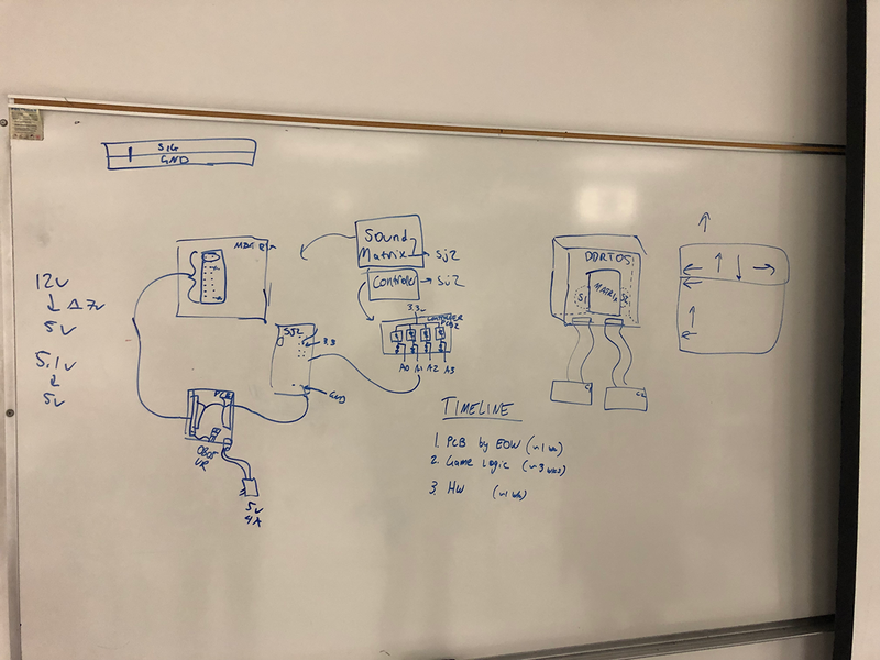
[[File:PCB OriginalBrainstorm.png|800px|middle]] | [[File:PCB OriginalBrainstorm.png|800px|middle]] | ||
| − | + | ||
| + | Original brainstorm idea for PCBs and Enclosure and Timeline | ||
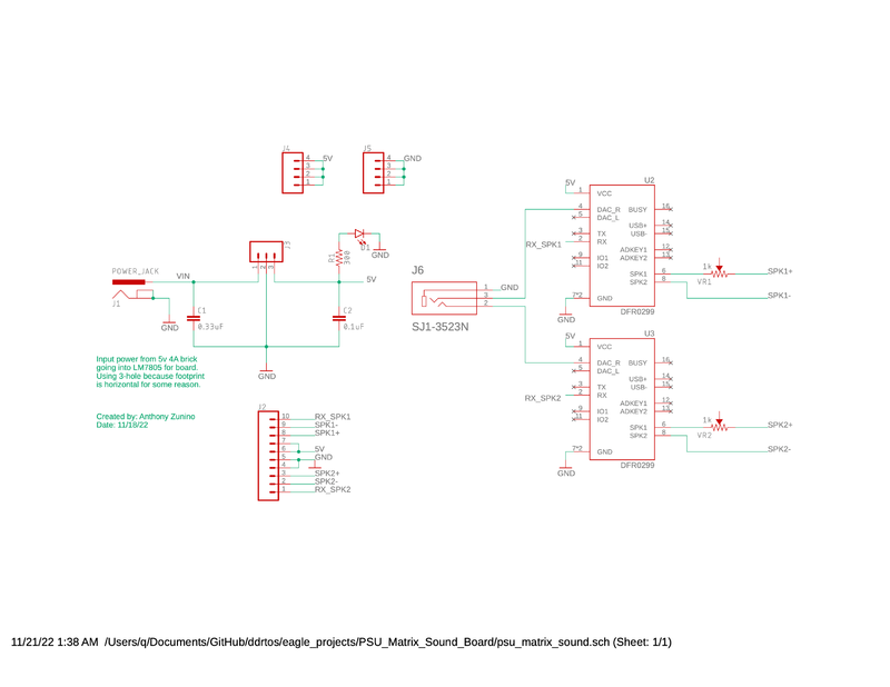
[[File:PCB psu matrix soundSch.png|800px|middle]] | [[File:PCB psu matrix soundSch.png|800px|middle]] | ||
| − | + | ||
| + | Schematic for the PSU | ||
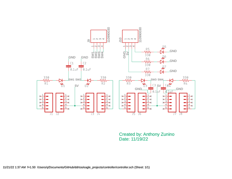
[[File:PCB controllerSch.png|800px|middle]] | [[File:PCB controllerSch.png|800px|middle]] | ||
| − | + | ||
| + | Schematic for the controller - note that there is a minor error with the switch inputs tied directly to GND and the caps messed up the LEDs | ||
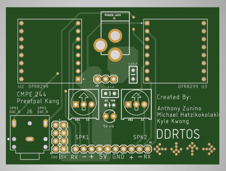
[[File:PCB PSUMatrixSoundBoardPCB.jpg|800px|middle]] | [[File:PCB PSUMatrixSoundBoardPCB.jpg|800px|middle]] | ||
| − | + | ||
| + | PSU, sound, and LED Matrix power PCB containing two MP3 decoders for multiple sound effects which port to an AUX output, extra 5V/GND pins, a power jack and 5V voltage regulator, and a neat DDR design. | ||
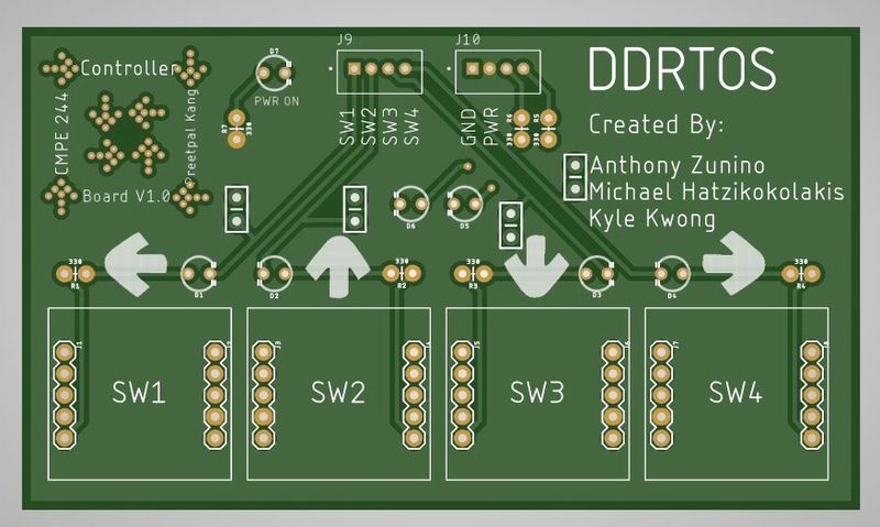
[[File:PCB ControllerBoardPCB.jpg|800px|middle]] | [[File:PCB ControllerBoardPCB.jpg|800px|middle]] | ||
| − | + | ||
| + | The controller PCB which takes in 5V and GND, and outputs four GPIO switch inputs using SeeedStudio 4-pin connectors. | ||
| + | |||
| Line 301: | Line 319: | ||
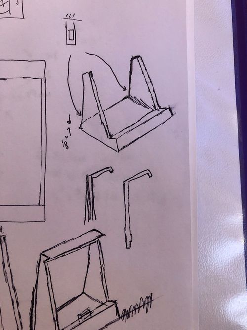
[[File:Enclosure Drawings.jpg|500px|middle]] | [[File:Enclosure Drawings.jpg|500px|middle]] | ||
| − | + | ||
| + | Some original drawing ideas for the base of the enclosure, the enclosure drawing can be seen on the left, and backplate cover in the middle. What is not shown are the pages of mistakes, bad drawings, and measurements down to the 0.01mm for 3D printing. | ||
[[File:111.png|500px|middle]] | [[File:111.png|500px|middle]] | ||
| − | |||
| + | The enclosure, with a slot for a piece of plastic to slide through and keep the LED Matrix from falling out. The opening in the back allows access to the power and ribbon-cable connections to the matrix | ||
[[File:222.png|500px|middle]] | [[File:222.png|500px|middle]] | ||
| − | + | ||
| + | The base which the enclosure connects to with the little tab on the slanted holder. The tabs in the back allow the PSU and SJ2 cases to connect and not jostle around | ||
[[File:333.png|500px]] | [[File:333.png|500px]] | ||
| − | + | ||
| + | The PSU, SJ2, and Controller cases from top-left to top-right to bottom. The openings allow access to the terminal block, power jack, micro-USB on SJ2, and the connectors on the controller. | ||
[[File:444.png|500px]] | [[File:444.png|500px]] | ||
| − | + | ||
| + | The backplate cover for the base. No connections except some material to make hot-gluing to the base easier. | ||
| + | |||
| + | In order to reproduce the enclosure, use the attached FreeCAD file in ddrtos/enclosure_cad to create .stl files for each part, or use the .stls saved in the ddrtos GitLab repo. Then use a slicer like Cura to generate G-code to upload to a 3D printer. | ||
| + | |||
| + | In order to reproduce the PCBs, take the gerber files located in the ddrtos/eagle_projects/controller and ddrtos/eagle_projects/PSU_Matrix_Sound_Board directories and go to pcbway.com to quote the boards. They take about 10 days (including weekends) to come in. | ||
| + | |||
* Mechanical Keyboard Switches, Keycaps, and Breakout Board | * Mechanical Keyboard Switches, Keycaps, and Breakout Board | ||
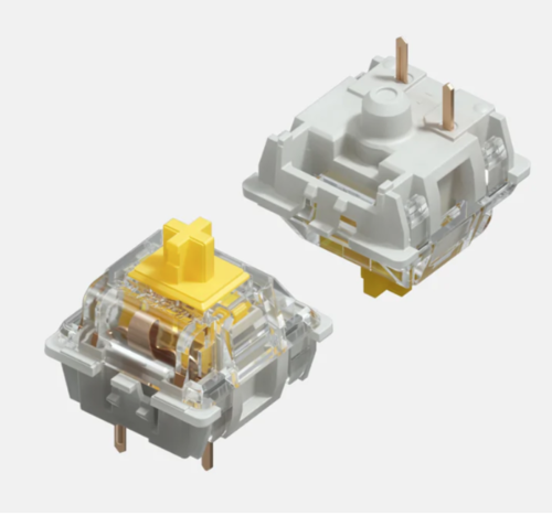
| + | Mechanical switches usually have one to three plastic pins for stabilizing on the PCB. However, those pins also made it would be nearly impossible to use them on a breadboard during early development. As a result, we used the Neokey breakout boards. The breakouts were solely used for the alignment of the yellow switch as seen below: | ||
| + | |||
| + | [[File:555.png|500px]] | ||
| + | |||
| + | Top and bottom view of the yellow switches used as switch inputs for the game | ||
| + | |||
| + | The two pins on the bottom side and stabilizing pin made making a PCB footprint for the switch difficult, so a breakout board with standard 0.1” spacing was much easier, just a little more expensive. There is an open source library for MX style footprint for KiCad[https://github.com/perigoso/keyswitch-kicad-library], however, because Eagle does not have support for library conversion, we were not able to take advantage of the library, and as a result, decided to use the breakout board for the PCB design. | ||
| + | |||
| + | As for keycaps, we chose DSA keycaps because Kyle thinks that for a flat controller design, uniform profile keycaps would provide the most comfort. | ||
| + | |||
* Power | * Power | ||
| Line 323: | Line 360: | ||
=== Hardware Interface === | === Hardware Interface === | ||
| − | |||
* DFmini MP3 Module | * DFmini MP3 Module | ||
** The MP3 module uses UART to receive instructions from SJ2, with a baud rate of 9600. | ** The MP3 module uses UART to receive instructions from SJ2, with a baud rate of 9600. | ||
** You can select the playback source by sending it the select playback device instruction (0x09). We chose SD card (parameter 0x0002) as our playback source because it requires the least amount of signal processing. | ** You can select the playback source by sending it the select playback device instruction (0x09). We chose SD card (parameter 0x0002) as our playback source because it requires the least amount of signal processing. | ||
** The module is able to play from 0001.mp3 up to 2999.mp3. | ** The module is able to play from 0001.mp3 up to 2999.mp3. | ||
| + | * LED Matrix | ||
| + | ** A guide for interfacing with an LED matrix was followed and produced expected results. [http://books.socialledge.com/books/embedded-drivers-real-time-operating-systems/page/led-matrix-driver] | ||
| + | |||
| + | === Hardware Design === | ||
| + | * PCB | ||
| + | Eagle was used to design the PCBs and PCBWay to order, manufacture, and ship the PCBs to the US. The schematics shown above helped create the bill of material (BOM) to order parts from DigiKey, Adafruit, SparkFun, and Amazon. Once everything came in, it was a matter of soldering everything together and continuity testing to make sure everything would power up without shorting. The scariest part was the power regulator getting hot really quickly after only 5 minutes of minimal LED Matrix display, but otherwise on integration day everything was put together and worked for the most part. The button switches used pull-up resistors to make a rising-edge trigger, but it took a while to realize that the on-board 10k pull-ups on the SJ2 needed to be enabled to properly see the pulse. | ||
| + | |||
| + | [[File:PCB BuiltBoards.png|500px]] | ||
| + | |||
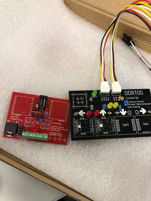
| + | A look at the PCBs (almost) fully built, as parts took a lot longer than expected to arrive. Note that the left-most connector on the controller PCB are all connected to GND, but the two yellow LEDs provide two extra GPIOs to provide any information to the player - originally designed to indicate player 1 and 2. | ||
| + | |||
| + | * 3D Printing | ||
| + | Use of 3D printing would help with creating a customizable enclosure and allow for clean connections and precise modeling. FreeCAD is a free, open-source software that is similar to Autodesk CAD and can create .stl files. Then a slicer, Cura, can take the .stl to create a gcode file to upload to a 3D printer. The 3D printer used in the project is the Artillery Sidewinder x1. | ||
| + | |||
| + | The main draw was being able to create custom cases for the PCBs and lock them onto the enclosure. Eventually, it became a hassle to reprint a design for a minor tweak (for example, the plastic store only went down to ⅛” thickness pieces, so the entire enclosure needed to be reprinted just a day before the demo!), so a broader approach like using cheap material would have been a better and quicker solution. | ||
| + | |||
| + | There are a total of six different printed pieces: the enclosure, the base, the PSU case, the controller case, the SJ2 case, and the base backplate. Each has its own FreeCAD design, .stl, and generated gcode. Overall, a total of 84 hours of printing and almost 1kg of PLA filament was used to create four different versions of the base, three different versions of the enclosure, and a single version of each of the cases. | ||
| + | |||
| + | [[File:Enclosure 3DPrint.JPG|500px]] | ||
| + | |||
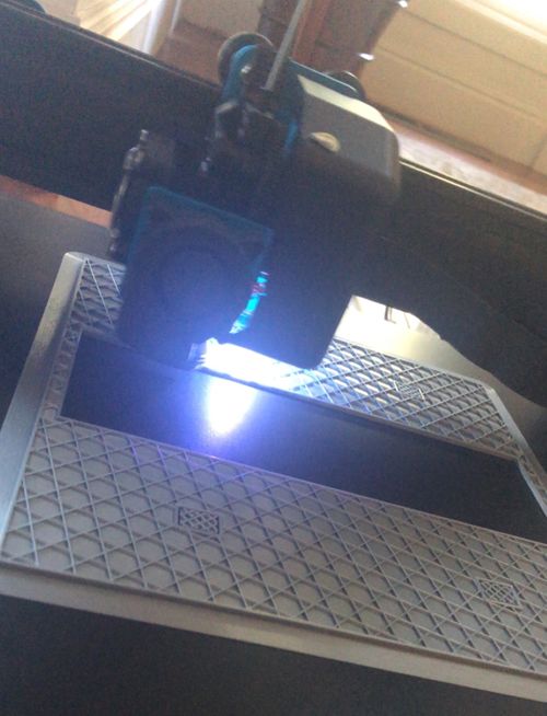
| + | View of the first draft of the enclosure mid-print - 12 hours done (for 1.5mm of height), only 5 more hours to go! | ||
| + | |||
| + | [[File:Enclosure DraftPrint.png|500px]] | ||
| + | |||
| + | View of the first enclosure draft which takes into account the power/ribbon cable on the back of the LED Matrix, a little bit of tape, and a large breadboard for prototyping to the left | ||
| + | |||
| + | [[File:Enclosure WithPCBs.png|500px]] | ||
| + | |||
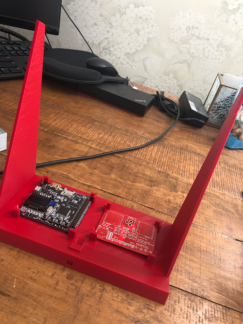
| + | View of the penultimate base print showing the 0.01mm precise fittings for the PCBs. Unfortunately, the cables out of the PSU (on the right) interfered with the enclosure so a final draft was needed for clearance… another 16 hour print! | ||
| + | |||
| + | [[File:666.png|500px]] | ||
| + | |||
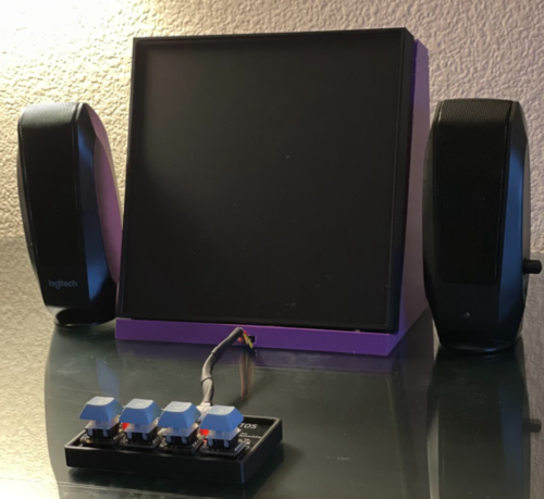
| + | Full front view of the entire project with the plastic screen, cases, speakers, and wiring. | ||
| + | |||
| + | [[File:777.png|500px]] | ||
| + | |||
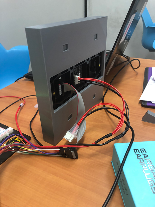
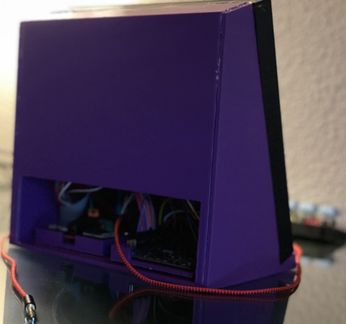
| + | Full back view with aux cord and a missing power cable to the PSU PCB (on the left) and all the wiring hidden by the backplate base cover. | ||
=== Software Design === | === Software Design === | ||
| − | |||
| − | |||
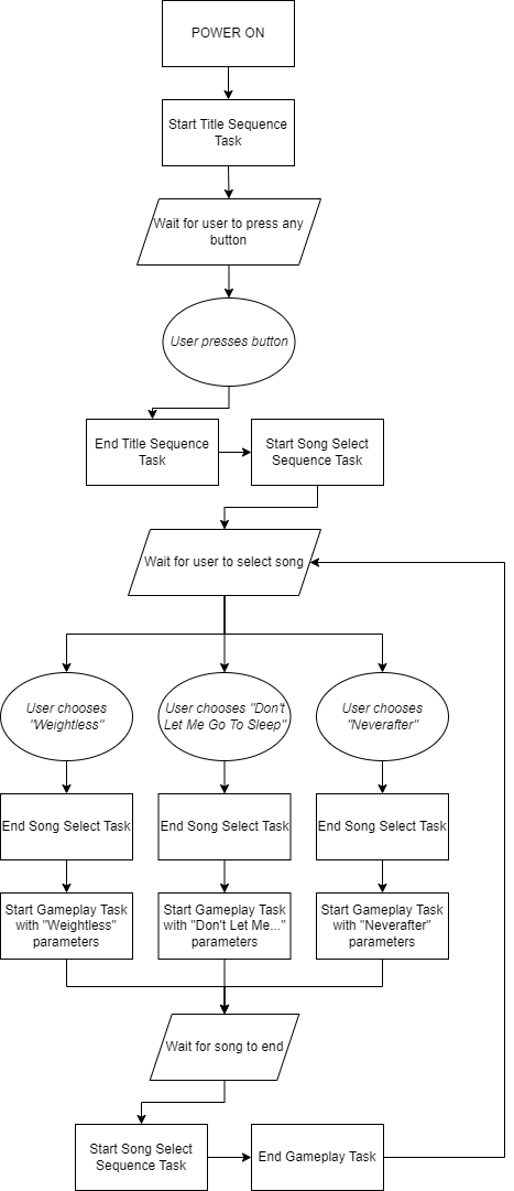
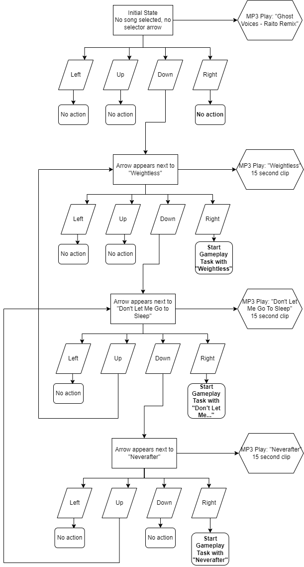
[[File:Software_State_Diagram(DDRTOS).png]] | [[File:Software_State_Diagram(DDRTOS).png]] | ||
| − | |||
| − | |||
=== Implementation === | === Implementation === | ||
| − | + | ==== MP3 module driver ==== | |
| − | + | * The driver has 5 public functions. | |
| − | + | * We dedicated one pin for each UART port | |
| − | + | * <code>void mp3_module__init(uart_e uart_to_use)</code> | |
| − | + | ** This function sets the dedicated pin for the selected UART port to UART mode, initializes the UART, and selects SD card as the playback source. If the GENUINE macro is set to 1, it also sets the volume to 10. | |
| − | + | * <code>void mp3_module__play(uart_e uart_to_use, uint32_t song_number)</code> | |
| − | + | ** This function sends the instruction to the mp3 module to play the song with the name song_number.mp3. It checks to make sure that the song_number is less than or equal to 2999. | |
| − | + | * <code>void mp3_module__resume(uart_e uart_to_use)</code> | |
| − | + | ** This function resumes a paused song. | |
| − | + | * <code>void mp3_module__pause(uart_e uart_to_use)</code> | |
| − | + | ** This function pauses a playing song. | |
| − | + | * <code>void mp3_module__reset_playback(uart_e uart_to_use)</code> | |
| − | + | ** This function resets the module. | |
| − | |||
{| class="wikitable" | {| class="wikitable" | ||
|- | |- | ||
| Line 367: | Line 435: | ||
| 4.28 | | 4.28 | ||
|} | |} | ||
| + | ==== Title Sequence==== | ||
| + | [[File:DDRTOS_Title_sequence.gif]] | ||
| + | <pre> | ||
| + | // title_sequence.h | ||
| + | #pragma once | ||
| + | |||
| + | #include "FreeRTOS.h" | ||
| + | #include "task.h" | ||
| + | |||
| + | TaskHandle_t title_logo_sequence; | ||
| + | |||
| + | void title_logo(void *p); | ||
| + | |||
| + | void press_to_start__handler(void); | ||
| + | </pre> | ||
| + | |||
| + | * Overview | ||
| + | ** The title sequence serves two purposes. It provides an introductory credits screen, followed by a brief animation of the letters “DDR” in red moving downwards and the letters “RTOS” in blue moving upwards to combine and form “DDRTOS” with the shared letter “R” changed to the color purple. This entire scene is set to the song “Ghost Voices” by Virtual Self, with the names in the credits appearing and disappearing to the beat of the song, and the acronyms merging at the drop of the song. After the acronym merge and a one second delay, the text “Press Anywhere To Start” appears below the logo and the player is able to press any button on the controller to clear the screen, stop the music, and advance to the song select sequence. There is no way to return to the title screen without resetting the system. | ||
| + | |||
| + | * Tasks | ||
| + | ** Title Sequence only involves one task, <code>void title_logo(void *p)</code>, which steps through each part of the sequence before calling the next sequence and suspending itself. | ||
| + | |||
| + | * Exposed Functions | ||
| + | ** The only exposed function is <code>void press_to_start__handler(void)</code> which is meant to be called from the <code>button.c</code> state machine. | ||
| + | |||
| + | ==== Song Select ==== | ||
| + | [[File:Song_select_demo.gif]] | ||
| + | <pre> | ||
| + | // song_select.h | ||
| + | #include "FreeRTOS.h" | ||
| + | #include "task.h" | ||
| + | |||
| + | TaskHandle_t song_select_sequence; | ||
| + | TaskHandle_t strobe_song_handler; | ||
| + | TaskHandle_t song_preview_handler; | ||
| + | TaskHandle_t song_pause_handler; | ||
| + | |||
| + | void song_select(void *p); | ||
| + | void strobe_choose_your_song(void *p); | ||
| + | void sleep_on_semaphore_song_preview(void *p); | ||
| + | void pause_song_task_to_elim_starting_delay(void *p); | ||
| + | |||
| + | void song_menu_move_selector_up__handler(void); | ||
| + | void song_menu_move_selector_down__handler(void); | ||
| + | void song_menu_confirm_song_choice__handler(void); | ||
| + | |||
| + | uint8_t get__selected_song(void); | ||
| + | </pre> | ||
| + | |||
| + | * Overview | ||
| + | ** Song Select allows player input to determine which song they’d like to select to play. Upon loading, it plays the song “Ghost Voices (Raito Remix)” before the user takes any action. Moving the arrow keys down and up displays a small green arrow next to the song names to indicate which song is currently selected. When a song is selected, a 15 second preview of the song plays with fade in and fade out effects. Pressing the right arrow key when a song is selected will clear the screen for everything besides the song title and arrow selector, delay, then clear it too. After the song gameplay has finished, this task will be returned to. | ||
| + | |||
| + | * Tasks | ||
| + | ** <code>void song_select(void *p)</code> | ||
| + | *** Main flow of this sequence, handles the overall flow for this task. | ||
| + | ** <code>void strobe_choose_your_song(void *p)</code> | ||
| + | ***Simply strobes the words “Choose Your Song” to the beat of the main song while changing colors. Also handles changing the border colors at the same timing. | ||
| + | ** <code>void sleep_on_semaphore_song_preview(void *p)</code> | ||
| + | *** Takes a semaphore given by a function called by an interrupt detected in button.c. This handles the displaying of the selector arrow as well as sending the command to play the preview song. | ||
| + | ** <code>void pause_song_task_to_elim_starting_delay(void *p)</code> | ||
| + | *** This task was created to fix a bug. There was an issue involving indeterministic timing of the gameplay task that was initially thought to be caused by calling MP3 tasks in the main task, but this proved to not be the cause. | ||
| + | |||
| + | * Exposed Functions | ||
| + | ** <code>void song_menu_move_selector_xx__handler(void)</code> | ||
| + | *** Sets a static global variable for the currently selected song when browsing through the options with the up and down arrow keys. | ||
| + | ** <code>void song_menu_confirm_song_choice(void)</code> | ||
| + | *** Sets a static global variable to let the main task know it can proceed to its final stages and call the Gameplay task. | ||
| + | ** <code>uint8_t get__selected_song(void)</code> | ||
| + | *** A getter made to see the value of the selected song. This function is called by the Gameplay task so it can know which song to load. | ||
| + | [[File:Song_Select_State_Diagram(DDRTOS).png]] | ||
| + | ==== Gameplay ==== | ||
| + | [[File:Weightless_demo.gif]] | ||
| + | [[File:Neverafter_demo.gif]] | ||
| + | [[File:Don%27t_Let_Me_Go_To_Sleep_demo.gif]] | ||
| + | *Overview | ||
| + | **Depending on which song was selected in Song Select, a “beatmap” is loaded and some initial parameters are set. The mp3 module starts playing the song as arrows start moving from the bottom to the top of the screen. Whenever a key is pressed, the game checks the arrow outline at the top of the screen to see if there’s an arrow currently filling it. If there is, the player scores a point multiplied by the current multiplier. Hitting consecutive notes increases the score multiplier, up to a maximum value of 4. Notes can be skipped with no penalty, but a penalty is incurred for hitting a key when the corresponding outline is not filled. This involves losing 1 point, but more importantly, resetting your score multiplier to one. | ||
| + | |||
| + | *Tasks | ||
| + | ** <code>void game_logic(void *p)</code> | ||
| + | *** Main flow of this sequence, handles the overall flow for this task. | ||
| + | ** <code>void shift_matrix(void *p)</code> | ||
| + | *** Calls a function from led_matrix.c to move the matrix rows upwards. This gives the appearance of each arrow moving up. The columns containing the green lanes are exempt from shifting, as well as the top 5 rows containing the score and multiplier information. The red arrow outlines are erased before the row shift, and drawn again after the row shift so as to keep them from moving. | ||
| + | *** An important note is that a delay parameter is read by this task. This controls the delay between row shift operations. This can make the action slower or faster based on the length of the delay, which is a factor in increasing the difficulty of a song. | ||
| + | ** <code>void update_score(void *p)</code> | ||
| + | *** Reads the score value from a static global value and updates the text on screen. | ||
| + | ** <code>void sleep_on_semaphore_sound_effect(void *p)</code> | ||
| + | *** Takes a semaphore given by a function called by an interrupt detected in button.c. This handles the playing of sound effects for both hitting and missing notes. | ||
| + | *Exposed Functions | ||
| + | ** <code>bool determine_score_if_pixel_detected__handler(uint32_t pixel_y, uint32_t pixel_x)</code> | ||
| + | *** This function is called by an interrupt in button.c to check whether a note is in an outline so that points may be added for a hit and subtracted for a miss. | ||
| + | |||
| + | ====Additional Libraries==== | ||
| + | <pre> | ||
| + | // button.h | ||
| + | #pragma once | ||
| + | |||
| + | typedef enum { | ||
| + | title__state, | ||
| + | song_select__state, | ||
| + | song_select_wait__state, | ||
| + | gameplay__state, | ||
| + | } game_state_e; | ||
| + | |||
| + | void set__game_state(game_state_e next_game_state); | ||
| + | |||
| + | void all_buttons__init(void); | ||
| + | </pre> | ||
| + | <code>button.c</code> | ||
| + | * Overview | ||
| + | ** The advantage to using keyboard buttons for input is an intuitive way to interact with the user interface. The arrow buttons can be used for very different purposes depending on which state of the game is currently active. When the Title Sequence is active, any button press will suffice to move the logic forward. When the Song Select Sequence is active, the left button is disabled, the up and down arrows move between songs, and the right arrow confirms the song and moves the logic along. When the Gameplay Sequence is active, the arrows are used for striking notes. This is handled by a switch case state machine within button.c. Rather than processing the logic of what should happen when a button is pressed within this file, that logic is exported to public functions across the rest of the codebase. This keeps the state machine clean and easy to understand. | ||
| + | |||
| + | * Exposed Functions | ||
| + | ** <code>void set__game_state(game_state_e next_game_state)</code> | ||
| + | *** A setter used by each of the three primary sequence tasks to update the button state machine with the current task. | ||
| + | ** <code>void all_buttons__init(void)</code> | ||
| + | *** Sets all button GPIO pins to inputs and attaches interrupt handlers to them. This function is called once at the beginning of main.c | ||
| + | |||
| + | <code>symbols.c</code> | ||
| + | <pre> | ||
| + | void draw__A_small(uint8_t top_left_corner_row, uint8_t top_left_corner_col, color_code color); | ||
| + | void draw__B_small(uint8_t top_left_corner_row, uint8_t top_left_corner_col, color_code color); | ||
| + | void draw__C_small(uint8_t top_left_corner_row, uint8_t top_left_corner_col, color_code color); | ||
| + | ... | ||
| + | </pre> | ||
| + | * A library written to make writing the alphabet, numbers, and gameplay items simple. Most functions take a row and column position as input, as well as color. The row and column position refers to the top left corner of the “box” that would hold the value. This keeps the system standardized to make writing words easier. | ||
== Testing & Technical Challenges == | == Testing & Technical Challenges == | ||
| − | |||
| − | |||
| − | + | ===Bugs that had to be worked around=== | |
| + | * Audio sync issue | ||
| + | ** Even finding standard 120 beat per minute (BPM) songs to set the timing between notes to 500ms did not work. There was always an inherent delay that was not fixed using vTaskDelayUntil() | ||
| + | ** We tried enabling the trace library, but it seems that the FreeRTOS version is incompatible with trace library, so we were unable to verify the timing issues with the trace library | ||
| + | ** Eventually the beat maps, or the mapping of arrows and timing of when they appear, had to be completely manually made | ||
| + | *** Some helpers were created to make the process a little faster, but some delays and a ton of back and forth between compiling and verifying the timing was needed | ||
| + | * Hardware issue with the mp3 module | ||
| + | ** Lesson Learned: Don’t cheap out. Always buy genuine products from reputable sites. We wasted many hours because we didn’t buy the genuine product | ||
| + | **Incompatible Instruction format | ||
| + | *** The genuine product has a 10-byte instruction format with the second and third last two bytes being the checksum. | ||
| + | *** However, the one we purchased didn’t have the checksum implemented, and the product page didn’t mention it. So after we wrote the mp3 module driver, we had no idea why it didn’t work. After spending hours reading the datasheets, doing printfs to the terminal, and even reading the logic analyzer output to check if the SJ2 was sending the correct data to the mp3 module. | ||
| + | *** Then we decided to read the reviews and see if others had the same issue, and we found out that the product we bought was not a genuine product, and did not implement all the functionalities that the genuine product has. | ||
| + | *** From our testing, the one we have omitted the checksum from the instruction format. Also, volume related instructions are also omitted from the mp3 module. | ||
| + | *** However, because the module does not have a built-in DSP, we are unable to make the sound effects overlap. | ||
| + | ** Indexing Issue | ||
| + | *** The user manual stated that song files on the SD card should be named “0001.mp3”, “0002.mp3”, “0003.mp3” and so on. When writing play commands to the mp3 module, a number could be supplied as a parameter and the corresponding song would be played. We discovered that after 5 songs, the MP3 module chose some other way of determining which song to play. Care had to be taken to test and check what the new order of songs was each time a new song was added to the SD card. An enumeration with the correct order was added and maintained in <code>song_info.h</code>. | ||
| − | === < | + | * Visible screen flicker |
| − | + | ** Title Sequence and Song Select Sequence both provided little competition for CPU time with the LED Matrix task. This changed when the Gameplay Tasks were active. The LED Matrix did not have enough CPU time to smoothly update the screen as it once did. This provided constant flicker throughout gameplay. Placing a plastic screen over the front of the LED screen made this effect less jarring. | |
| + | |||
| + | * Unstable Soldering Connection | ||
| + | ** The Eagle library for the LED has extremely small pads. As a result of that, we are unable to make good connections on the power indicator LED. | ||
| + | |||
| + | === Bugs that got fixed=== | ||
| + | * Able to move arrows after selecting song, changes song you picked | ||
| + | ** After a player selects their song in Song Select Sequence, the screen clears except for the text of the song title and the selector arrow before moving to the Gameplay Sequence. Pressing the arrow keys would still change the song and could result in a different song playing in the Gameplay Sequence than was intended. Adding a new state called “song_select_wait__state” to <code>button.h</code> allowed us to disable button input in this short time. | ||
| + | |||
| + | * Songs starting at different times due to MP3 module | ||
| + | ** It was observed that occasionally, the music would load approximately one second sooner than it should when starting a new song in the Gameplay Sequence. It was determined that if the song preview in the Song Select Sequence was allowed to play out for its full 15 second duration, then the MP3 module would automatically run a reset command to make it ready for the next song. If the player selected a song while the song preview was still running, the MP3 module would need to run that reset command and a subsequent play song command. This accounted for the difference in timings. A solution was found by forcing the task to run a stop command before running a play command, keeping timings consistent. | ||
| + | |||
| + | === Hardware limitation and possible solution === | ||
| + | Since our mp3 module can only play one file at a time, and does not have a built-in DSP, we used two mp3 modules, one for music playback and the other for sound effects. One of the line signals from the music module connects to the left channel of the aux port, and one of the line signals from the sound effect module connects to the right channel. We didn’t mix the signals into a full stereo because of time constraints. | ||
| + | In theory, we can get this done with only one mp3 module by using the onboard DSP on the SJ2 to decode the mp3 files, and sum the song and the sound effect together to create one signal that can be converted into audio with a DAC. | ||
== Conclusion == | == Conclusion == | ||
| Line 387: | Line 607: | ||
== References == | == References == | ||
| − | |||
| − | |||
| − | |||
| − | |||
[https://picaxe.com/docs/spe033.pdf DF Mini mp3 player] | [https://picaxe.com/docs/spe033.pdf DF Mini mp3 player] | ||
| − | + | [http://books.socialledge.com/books/embedded-drivers-real-time-operating-systems/page/led-matrix-driver LED Matrix Guide] | |
| − | |||
Latest revision as of 18:35, 15 December 2022
Contents
Abstract
Note: The frame rate is low because of the wiki upload limit
Rhythm games have been popular for years and date back to the 1970’s, but hit its stride in 1997 when one of the most notable and popular games released - Dance Dance Revolution (DDR). The main point of a rhythm game is to use music and challenge a player’s ability to stay on beat and typically press a button to the beat of the song. Our project is based and dedicated to DDR, as we all share a passion for music and video games. DDR is played with four arrows for each direction up, down, left, and right that need to be hit at the time of a beat in order to score and increase the multiplier. There are several aspects that are taken from other games like Guitar Hero and Friday Night Funkin’ (sound effects, multiplier, and artwork) that have also become a part of the project. Our project name, DDRTOS, is a combination of the game DDR and RTOS which runs the project.
Objectives & Introduction
Objective
- Create a DDR-like game on RTOS based system, hence the name DDRTOS
- Responsive button press
- Good Audio
- Good visual and audible response when hitting notes at the right time
Game Introduction
- After the title sequence, you'll be prompted to press any key to start.
- After you press any key, you'll be brought to the song selection screen.
- Press up or down to select song.
- Press right to confirm you choice, and the game starts.
- The arrows are mapped to the beat, so you should aim to hit the button when the static red arrow is fully lit up.
Team Members & Responsibilities
- Michael Hatzikokolakis Gitlab
- Core gameplay development
- Beatmap development
- Kyle Kwong Gitlab
- MP3 module driver development
- Audio system research and design
- Ensure coding standards
- Assist on all parts of the project
- Wiki Manager
- Anthony Zunino Gitlab
- Enclosure Design
- PCB Design
- Converted the mp3 module to use UART queue instead of polling
Schedule
| Week# | Start Date | End Date | Task | Status |
|---|---|---|---|---|
| 1 |
|
|
|
|
| 2 |
|
|
|
|
| 3 |
|
|
|
|
| 4 |
|
|
|
|
| 5 |
|
|
|
|
| 6 |
|
|
|
|
| 7 |
|
|
|
|
| 8 |
|
|
|
|
| 9 |
|
|
|
|
| 10 |
|
|
|
|
Parts List & Cost
Note: For the keycaps, we suggest using uniform profile keycaps such as DSA or XDA.
| Item# | Part Desciption | Vendor | Qty | Cost/Item |
|---|---|---|---|---|
| 1 | 64x64 RGB LED Matrix - 3mm Pitch (192mm x 192mm) | Adafruit [1] | 1 | $59.95 |
| 2 | MP3 Module | Amazon [2] | 1 | $12.99 |
| 3 | PCB | PCBWay [3] | 1 | $15.00 |
| 4 | NeoKey Socket Breakout for Mechanical Key Switches with NeoPixel – For MX Compatible Switches | Adafruit [4] | 4 | $1.75 |
| 5 | LM7805 Power Regulator | Digi-Key [5] | 1 | $0.75 |
| 6 | 10-pin Terminal Block | Digi-Key [6] | 1 | $3.86 |
| 7 | LEDs | Adafruit [7] | 8 | $0.50 |
| 8 | Mx style switches | Prevail [8] | 4 | $5.00 |
| 9 | Mx style keycaps | Adafruit [9] | 4 | $1.25 |
| 10 | SeeedStudio 4-pin connectors | SeedStudio [10] | 2 | $0.85 |
| 11 | 4-pin to wire connector cable | SeedStudio [11] | 2 | $1.60 |
| 12 | 20-pin ribbon cable | Adafruit [12] | 1 | $1.95 |
| 13 | Miscellaneous resistors and capacitors | N/A | N/A | N/A |
Design & Implementation
How to Reproduce
- PCB
Creation of the PCBs were the highest priority at the start of the project in order to begin development and integration with the entire system. The original idea was to create a single master PCB, but evolved into two boards; one board will be used as the PSU and sound wiring for the SJ2 and LED Matrix, and the other board as a controller for the game both of which including LEDs indicating power, descriptive silkscreen, and easter eggs for DDR.
Original brainstorm idea for PCBs and Enclosure and Timeline
Schematic for the PSU
Schematic for the controller - note that there is a minor error with the switch inputs tied directly to GND and the caps messed up the LEDs
PSU, sound, and LED Matrix power PCB containing two MP3 decoders for multiple sound effects which port to an AUX output, extra 5V/GND pins, a power jack and 5V voltage regulator, and a neat DDR design.
The controller PCB which takes in 5V and GND, and outputs four GPIO switch inputs using SeeedStudio 4-pin connectors.
- 3D Printed Enclosure
Originally, the enclosure’s design was meant to replicate that of an old stand-up retro video game machine. As the design progressed, we wanted to go with a smaller version of the retro machine that was angled and provided both access to the PSU and SJ2 boards in the back while also maintaining a small form factor.
Some original drawing ideas for the base of the enclosure, the enclosure drawing can be seen on the left, and backplate cover in the middle. What is not shown are the pages of mistakes, bad drawings, and measurements down to the 0.01mm for 3D printing.
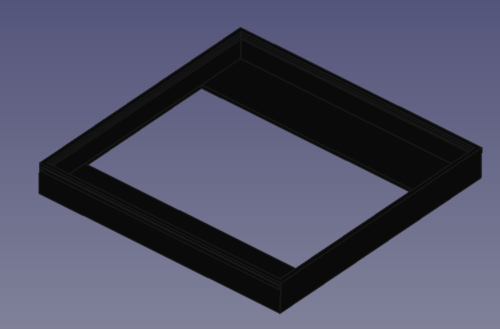
The enclosure, with a slot for a piece of plastic to slide through and keep the LED Matrix from falling out. The opening in the back allows access to the power and ribbon-cable connections to the matrix
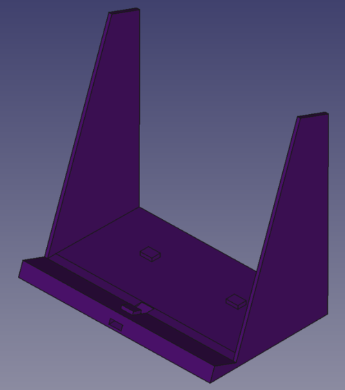
The base which the enclosure connects to with the little tab on the slanted holder. The tabs in the back allow the PSU and SJ2 cases to connect and not jostle around
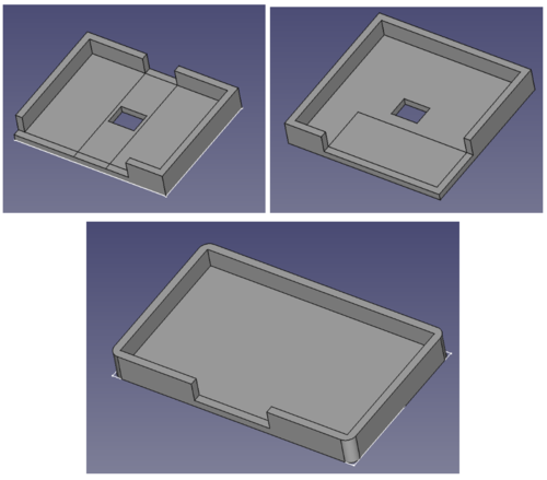
The PSU, SJ2, and Controller cases from top-left to top-right to bottom. The openings allow access to the terminal block, power jack, micro-USB on SJ2, and the connectors on the controller.
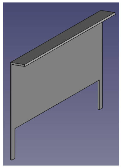
The backplate cover for the base. No connections except some material to make hot-gluing to the base easier.
In order to reproduce the enclosure, use the attached FreeCAD file in ddrtos/enclosure_cad to create .stl files for each part, or use the .stls saved in the ddrtos GitLab repo. Then use a slicer like Cura to generate G-code to upload to a 3D printer.
In order to reproduce the PCBs, take the gerber files located in the ddrtos/eagle_projects/controller and ddrtos/eagle_projects/PSU_Matrix_Sound_Board directories and go to pcbway.com to quote the boards. They take about 10 days (including weekends) to come in.
- Mechanical Keyboard Switches, Keycaps, and Breakout Board
Mechanical switches usually have one to three plastic pins for stabilizing on the PCB. However, those pins also made it would be nearly impossible to use them on a breadboard during early development. As a result, we used the Neokey breakout boards. The breakouts were solely used for the alignment of the yellow switch as seen below:
Top and bottom view of the yellow switches used as switch inputs for the game
The two pins on the bottom side and stabilizing pin made making a PCB footprint for the switch difficult, so a breakout board with standard 0.1” spacing was much easier, just a little more expensive. There is an open source library for MX style footprint for KiCad[13], however, because Eagle does not have support for library conversion, we were not able to take advantage of the library, and as a result, decided to use the breakout board for the PCB design.
As for keycaps, we chose DSA keycaps because Kyle thinks that for a flat controller design, uniform profile keycaps would provide the most comfort.
- Power
- Power bricks come in many different wattages and ratings, so a power jack and voltage regulator were the easiest solution to accommodate different power bricks while still providing a stable voltage for both the LED Matrix, SJ2 board, and controller. The traces on each of the PCBs were widened as much as possible to allow as much current to flow as needed, and the wires and terminal block connections were selected based on the specifications of the Matrix as it was the biggest power draw.
Hardware Interface
- DFmini MP3 Module
- The MP3 module uses UART to receive instructions from SJ2, with a baud rate of 9600.
- You can select the playback source by sending it the select playback device instruction (0x09). We chose SD card (parameter 0x0002) as our playback source because it requires the least amount of signal processing.
- The module is able to play from 0001.mp3 up to 2999.mp3.
- LED Matrix
- A guide for interfacing with an LED matrix was followed and produced expected results. [14]
Hardware Design
- PCB
Eagle was used to design the PCBs and PCBWay to order, manufacture, and ship the PCBs to the US. The schematics shown above helped create the bill of material (BOM) to order parts from DigiKey, Adafruit, SparkFun, and Amazon. Once everything came in, it was a matter of soldering everything together and continuity testing to make sure everything would power up without shorting. The scariest part was the power regulator getting hot really quickly after only 5 minutes of minimal LED Matrix display, but otherwise on integration day everything was put together and worked for the most part. The button switches used pull-up resistors to make a rising-edge trigger, but it took a while to realize that the on-board 10k pull-ups on the SJ2 needed to be enabled to properly see the pulse.
A look at the PCBs (almost) fully built, as parts took a lot longer than expected to arrive. Note that the left-most connector on the controller PCB are all connected to GND, but the two yellow LEDs provide two extra GPIOs to provide any information to the player - originally designed to indicate player 1 and 2.
- 3D Printing
Use of 3D printing would help with creating a customizable enclosure and allow for clean connections and precise modeling. FreeCAD is a free, open-source software that is similar to Autodesk CAD and can create .stl files. Then a slicer, Cura, can take the .stl to create a gcode file to upload to a 3D printer. The 3D printer used in the project is the Artillery Sidewinder x1.
The main draw was being able to create custom cases for the PCBs and lock them onto the enclosure. Eventually, it became a hassle to reprint a design for a minor tweak (for example, the plastic store only went down to ⅛” thickness pieces, so the entire enclosure needed to be reprinted just a day before the demo!), so a broader approach like using cheap material would have been a better and quicker solution.
There are a total of six different printed pieces: the enclosure, the base, the PSU case, the controller case, the SJ2 case, and the base backplate. Each has its own FreeCAD design, .stl, and generated gcode. Overall, a total of 84 hours of printing and almost 1kg of PLA filament was used to create four different versions of the base, three different versions of the enclosure, and a single version of each of the cases.
View of the first draft of the enclosure mid-print - 12 hours done (for 1.5mm of height), only 5 more hours to go!
View of the first enclosure draft which takes into account the power/ribbon cable on the back of the LED Matrix, a little bit of tape, and a large breadboard for prototyping to the left
View of the penultimate base print showing the 0.01mm precise fittings for the PCBs. Unfortunately, the cables out of the PSU (on the right) interfered with the enclosure so a final draft was needed for clearance… another 16 hour print!
Full front view of the entire project with the plastic screen, cases, speakers, and wiring.
Full back view with aux cord and a missing power cable to the PSU PCB (on the left) and all the wiring hidden by the backplate base cover.
Software Design
Implementation
MP3 module driver
- The driver has 5 public functions.
- We dedicated one pin for each UART port
-
void mp3_module__init(uart_e uart_to_use)- This function sets the dedicated pin for the selected UART port to UART mode, initializes the UART, and selects SD card as the playback source. If the GENUINE macro is set to 1, it also sets the volume to 10.
-
void mp3_module__play(uart_e uart_to_use, uint32_t song_number)- This function sends the instruction to the mp3 module to play the song with the name song_number.mp3. It checks to make sure that the song_number is less than or equal to 2999.
-
void mp3_module__resume(uart_e uart_to_use)- This function resumes a paused song.
-
void mp3_module__pause(uart_e uart_to_use)- This function pauses a playing song.
-
void mp3_module__reset_playback(uart_e uart_to_use)- This function resets the module.
| UART Port | UART_0 | UART_1 | UART_2 | UART_3 |
|---|---|---|---|---|
| GPIO Port.Pin | 0.0 | 2.0 | 0.10 | 4.28 |
Title Sequence
// title_sequence.h
#pragma once

#include "FreeRTOS.h"
#include "task.h"

TaskHandle_t title_logo_sequence;

void title_logo(void *p);

void press_to_start__handler(void);
- Overview
- The title sequence serves two purposes. It provides an introductory credits screen, followed by a brief animation of the letters “DDR” in red moving downwards and the letters “RTOS” in blue moving upwards to combine and form “DDRTOS” with the shared letter “R” changed to the color purple. This entire scene is set to the song “Ghost Voices” by Virtual Self, with the names in the credits appearing and disappearing to the beat of the song, and the acronyms merging at the drop of the song. After the acronym merge and a one second delay, the text “Press Anywhere To Start” appears below the logo and the player is able to press any button on the controller to clear the screen, stop the music, and advance to the song select sequence. There is no way to return to the title screen without resetting the system.
- Tasks
- Title Sequence only involves one task,
void title_logo(void *p), which steps through each part of the sequence before calling the next sequence and suspending itself.
- Title Sequence only involves one task,
- Exposed Functions
- The only exposed function is
void press_to_start__handler(void)which is meant to be called from thebutton.cstate machine.
- The only exposed function is
Song Select
// song_select.h
#include "FreeRTOS.h"
#include "task.h"

TaskHandle_t song_select_sequence;
TaskHandle_t strobe_song_handler;
TaskHandle_t song_preview_handler;
TaskHandle_t song_pause_handler;

void song_select(void *p);
void strobe_choose_your_song(void *p);
void sleep_on_semaphore_song_preview(void *p);
void pause_song_task_to_elim_starting_delay(void *p);

void song_menu_move_selector_up__handler(void);
void song_menu_move_selector_down__handler(void);
void song_menu_confirm_song_choice__handler(void);

uint8_t get__selected_song(void);
- Overview
- Song Select allows player input to determine which song they’d like to select to play. Upon loading, it plays the song “Ghost Voices (Raito Remix)” before the user takes any action. Moving the arrow keys down and up displays a small green arrow next to the song names to indicate which song is currently selected. When a song is selected, a 15 second preview of the song plays with fade in and fade out effects. Pressing the right arrow key when a song is selected will clear the screen for everything besides the song title and arrow selector, delay, then clear it too. After the song gameplay has finished, this task will be returned to.
- Tasks
-
void song_select(void *p)- Main flow of this sequence, handles the overall flow for this task.
-
void strobe_choose_your_song(void *p)- Simply strobes the words “Choose Your Song” to the beat of the main song while changing colors. Also handles changing the border colors at the same timing.
-
void sleep_on_semaphore_song_preview(void *p)- Takes a semaphore given by a function called by an interrupt detected in button.c. This handles the displaying of the selector arrow as well as sending the command to play the preview song.
-
void pause_song_task_to_elim_starting_delay(void *p)- This task was created to fix a bug. There was an issue involving indeterministic timing of the gameplay task that was initially thought to be caused by calling MP3 tasks in the main task, but this proved to not be the cause.
-
- Exposed Functions
-
void song_menu_move_selector_xx__handler(void)- Sets a static global variable for the currently selected song when browsing through the options with the up and down arrow keys.
-
void song_menu_confirm_song_choice(void)- Sets a static global variable to let the main task know it can proceed to its final stages and call the Gameplay task.
-
uint8_t get__selected_song(void)- A getter made to see the value of the selected song. This function is called by the Gameplay task so it can know which song to load.
-
Gameplay
- Overview
- Depending on which song was selected in Song Select, a “beatmap” is loaded and some initial parameters are set. The mp3 module starts playing the song as arrows start moving from the bottom to the top of the screen. Whenever a key is pressed, the game checks the arrow outline at the top of the screen to see if there’s an arrow currently filling it. If there is, the player scores a point multiplied by the current multiplier. Hitting consecutive notes increases the score multiplier, up to a maximum value of 4. Notes can be skipped with no penalty, but a penalty is incurred for hitting a key when the corresponding outline is not filled. This involves losing 1 point, but more importantly, resetting your score multiplier to one.
- Tasks
-
void game_logic(void *p)- Main flow of this sequence, handles the overall flow for this task.
-
void shift_matrix(void *p)- Calls a function from led_matrix.c to move the matrix rows upwards. This gives the appearance of each arrow moving up. The columns containing the green lanes are exempt from shifting, as well as the top 5 rows containing the score and multiplier information. The red arrow outlines are erased before the row shift, and drawn again after the row shift so as to keep them from moving.
- An important note is that a delay parameter is read by this task. This controls the delay between row shift operations. This can make the action slower or faster based on the length of the delay, which is a factor in increasing the difficulty of a song.
-
void update_score(void *p)- Reads the score value from a static global value and updates the text on screen.
-
void sleep_on_semaphore_sound_effect(void *p)- Takes a semaphore given by a function called by an interrupt detected in button.c. This handles the playing of sound effects for both hitting and missing notes.
-
- Exposed Functions
-
bool determine_score_if_pixel_detected__handler(uint32_t pixel_y, uint32_t pixel_x)- This function is called by an interrupt in button.c to check whether a note is in an outline so that points may be added for a hit and subtracted for a miss.
-
Additional Libraries
// button.h
#pragma once

typedef enum {
  title__state,
  song_select__state,
  song_select_wait__state,
  gameplay__state,
} game_state_e;

void set__game_state(game_state_e next_game_state);

void all_buttons__init(void);
button.c
- Overview
- The advantage to using keyboard buttons for input is an intuitive way to interact with the user interface. The arrow buttons can be used for very different purposes depending on which state of the game is currently active. When the Title Sequence is active, any button press will suffice to move the logic forward. When the Song Select Sequence is active, the left button is disabled, the up and down arrows move between songs, and the right arrow confirms the song and moves the logic along. When the Gameplay Sequence is active, the arrows are used for striking notes. This is handled by a switch case state machine within button.c. Rather than processing the logic of what should happen when a button is pressed within this file, that logic is exported to public functions across the rest of the codebase. This keeps the state machine clean and easy to understand.
- Exposed Functions
-
void set__game_state(game_state_e next_game_state)- A setter used by each of the three primary sequence tasks to update the button state machine with the current task.
-
void all_buttons__init(void)- Sets all button GPIO pins to inputs and attaches interrupt handlers to them. This function is called once at the beginning of main.c
-
symbols.c
void draw__A_small(uint8_t top_left_corner_row, uint8_t top_left_corner_col, color_code color);
void draw__B_small(uint8_t top_left_corner_row, uint8_t top_left_corner_col, color_code color);
void draw__C_small(uint8_t top_left_corner_row, uint8_t top_left_corner_col, color_code color);
...
- A library written to make writing the alphabet, numbers, and gameplay items simple. Most functions take a row and column position as input, as well as color. The row and column position refers to the top left corner of the “box” that would hold the value. This keeps the system standardized to make writing words easier.
Testing & Technical Challenges
Bugs that had to be worked around
- Audio sync issue
- Even finding standard 120 beat per minute (BPM) songs to set the timing between notes to 500ms did not work. There was always an inherent delay that was not fixed using vTaskDelayUntil()
- We tried enabling the trace library, but it seems that the FreeRTOS version is incompatible with trace library, so we were unable to verify the timing issues with the trace library
- Eventually the beat maps, or the mapping of arrows and timing of when they appear, had to be completely manually made
- Some helpers were created to make the process a little faster, but some delays and a ton of back and forth between compiling and verifying the timing was needed
- Hardware issue with the mp3 module
- Lesson Learned: Don’t cheap out. Always buy genuine products from reputable sites. We wasted many hours because we didn’t buy the genuine product
- Incompatible Instruction format
- The genuine product has a 10-byte instruction format with the second and third last two bytes being the checksum.
- However, the one we purchased didn’t have the checksum implemented, and the product page didn’t mention it. So after we wrote the mp3 module driver, we had no idea why it didn’t work. After spending hours reading the datasheets, doing printfs to the terminal, and even reading the logic analyzer output to check if the SJ2 was sending the correct data to the mp3 module.
- Then we decided to read the reviews and see if others had the same issue, and we found out that the product we bought was not a genuine product, and did not implement all the functionalities that the genuine product has.
- From our testing, the one we have omitted the checksum from the instruction format. Also, volume related instructions are also omitted from the mp3 module.
- However, because the module does not have a built-in DSP, we are unable to make the sound effects overlap.
- Indexing Issue
- The user manual stated that song files on the SD card should be named “0001.mp3”, “0002.mp3”, “0003.mp3” and so on. When writing play commands to the mp3 module, a number could be supplied as a parameter and the corresponding song would be played. We discovered that after 5 songs, the MP3 module chose some other way of determining which song to play. Care had to be taken to test and check what the new order of songs was each time a new song was added to the SD card. An enumeration with the correct order was added and maintained in
song_info.h.
- The user manual stated that song files on the SD card should be named “0001.mp3”, “0002.mp3”, “0003.mp3” and so on. When writing play commands to the mp3 module, a number could be supplied as a parameter and the corresponding song would be played. We discovered that after 5 songs, the MP3 module chose some other way of determining which song to play. Care had to be taken to test and check what the new order of songs was each time a new song was added to the SD card. An enumeration with the correct order was added and maintained in
- Visible screen flicker
- Title Sequence and Song Select Sequence both provided little competition for CPU time with the LED Matrix task. This changed when the Gameplay Tasks were active. The LED Matrix did not have enough CPU time to smoothly update the screen as it once did. This provided constant flicker throughout gameplay. Placing a plastic screen over the front of the LED screen made this effect less jarring.
- Unstable Soldering Connection
- The Eagle library for the LED has extremely small pads. As a result of that, we are unable to make good connections on the power indicator LED.
Bugs that got fixed
- Able to move arrows after selecting song, changes song you picked
- After a player selects their song in Song Select Sequence, the screen clears except for the text of the song title and the selector arrow before moving to the Gameplay Sequence. Pressing the arrow keys would still change the song and could result in a different song playing in the Gameplay Sequence than was intended. Adding a new state called “song_select_wait__state” to
button.hallowed us to disable button input in this short time.
- After a player selects their song in Song Select Sequence, the screen clears except for the text of the song title and the selector arrow before moving to the Gameplay Sequence. Pressing the arrow keys would still change the song and could result in a different song playing in the Gameplay Sequence than was intended. Adding a new state called “song_select_wait__state” to
- Songs starting at different times due to MP3 module
- It was observed that occasionally, the music would load approximately one second sooner than it should when starting a new song in the Gameplay Sequence. It was determined that if the song preview in the Song Select Sequence was allowed to play out for its full 15 second duration, then the MP3 module would automatically run a reset command to make it ready for the next song. If the player selected a song while the song preview was still running, the MP3 module would need to run that reset command and a subsequent play song command. This accounted for the difference in timings. A solution was found by forcing the task to run a stop command before running a play command, keeping timings consistent.
Hardware limitation and possible solution
Since our mp3 module can only play one file at a time, and does not have a built-in DSP, we used two mp3 modules, one for music playback and the other for sound effects. One of the line signals from the music module connects to the left channel of the aux port, and one of the line signals from the sound effect module connects to the right channel. We didn’t mix the signals into a full stereo because of time constraints. In theory, we can get this done with only one mp3 module by using the onboard DSP on the SJ2 to decode the mp3 files, and sum the song and the sound effect together to create one signal that can be converted into audio with a DAC.
Conclusion
Overall, the project was all encompassing of the topics learned over the semester; from binary semaphores and queues to interrupts to quick handlers, each and every lecture contributed to different parts of the project. There were difficulties in implementing all the tasks in a structured way in the beginning, but, as more code was modularized, a new structure to the codebase was developed to integrate each part of the project - for example, a sound effect could play from the mp3 module which is defined in the drivers layer, and it could be called quickly using a helper function defined in the top game logic layer. This helper is in an interrupt handler that was called by an ISR from a button rising-edge interrupt defined in the buttons module. Having this level of modularity made future implementation and additions quick and well-defined for readability. If things could have been done differently, ordering of all the parts and a very rough idea for how the entire game would progress would have saved a lot of time spent waiting for parts and with initial implementation. If there were more time to work on this project, more work could be added to the state machine to flesh out the game, as a lot of design went into the state machine near the demo deadline. Then, additional features like a high score system are easier to add and create a much more fun and competitive game. Overall, the project helped solidify the concepts learned in CMPE244 and development of the game was much more interesting since the solutions were all based on the background solidified in the first section of the course. There is no limit to what FreeRTOS can do besides the stack, CPU, and mental utilization!
