Difference between revisions of "F21: Space Rage"
Proj user2 (talk | contribs) (→LED Matrix) |
Proj user2 (talk | contribs) |
||
| (78 intermediate revisions by the same user not shown) | |||
| Line 1: | Line 1: | ||
| − | === | + | [[File:Space_rage_setup.jpg|800px|right]] |
| − | + | == '''SPACE RAGE''' == | |
| − | + | {| | |
| − | + | |[[File:Lives screen.gif |thumb|800px|'''Player Lives Screen''']] | |
| − | + | |[[File:Gameplay_countdown.gif |thumb|800px|'''Gameplay Countdown Sequence''']] | |
| − | + | |[[File:Title_screen.gif |thumb|800px|'''Gameover to Title Screen Sequence''']] | |
| − | + | |} | |
| − | |||
| − | |||
| − | |||
| − | |||
| − | |||
| − | |||
| − | |||
== Abstract == | == Abstract == | ||
| Line 26: | Line 19: | ||
== Objectives & Introduction == | == Objectives & Introduction == | ||
| − | |||
Space Rage is a two player game that tests the players reaction times and strategy in a fast paced arena similar to the Tron Light Cycle game. The players only means of defense and offence is the wall that is left behind them as they move. There were a few key objectives and features we wanted to implement into our game to make it feel more like an arcade game: | Space Rage is a two player game that tests the players reaction times and strategy in a fast paced arena similar to the Tron Light Cycle game. The players only means of defense and offence is the wall that is left behind them as they move. There were a few key objectives and features we wanted to implement into our game to make it feel more like an arcade game: | ||
| Line 33: | Line 25: | ||
* Fast responsive controls | * Fast responsive controls | ||
* High activity and quick rounds | * High activity and quick rounds | ||
| − | |||
===== Player Modes ===== | ===== Player Modes ===== | ||
| Line 40: | Line 31: | ||
===== Sound and Music ===== | ===== Sound and Music ===== | ||
| − | + | When we think of arcade games, the thought of immersive visuals is almost just as important as the sound design. For this project, we wanted to set ourselves apart with the sound design section of this project and use 3 MP3 decoders to offer immersive sound on 4 speakers(2 dedicated to stereo background music and the other 2 for sound effects one left and right channel for player 1 and 2 respectively). We opted to do this instead of using a singular MP3 decoder because if we did this option, we could have only played a single MP3 file at a time (either music or a sound effect) but not both concurrently. With the music not taking any breaks to play sound effects, the result of this was a more immersive playing experience. With proper timing of the sound effects, this would only help amplify how immersive it is if the sounds would line up within +/- 20 milliseconds of an appropriate event happening. | |
===== Fast responsive controls ===== | ===== Fast responsive controls ===== | ||
| − | / | + | We have constructed two arcade joystick pads for each of the two players which are wired to the arcade box. Although the controllers are wired, they have been tested to function properly for up to a 6ft cable. The controllers responsiveness are fast which is desired for a game such as Space Rage which is dependent on strategy and reaction time. The controllers are connected using a cat5e/cat6 cable and can be easily removed for easy transportation. |
===== High activity and quick rounds ===== | ===== High activity and quick rounds ===== | ||
| Line 49: | Line 40: | ||
=== Team Members & Responsibilities === | === Team Members & Responsibilities === | ||
| − | [[File:jbeardphoto.jpg| | + | [[File:jbeardphoto.jpg|250px|middle]] |
*'''''[https://www.linkedin.com/in/jonathan-beard-155840205/ Jonathan Beard]''''' '''''[https://gitlab.com/jbeard79 Gitlab]''''' | *'''''[https://www.linkedin.com/in/jonathan-beard-155840205/ Jonathan Beard]''''' '''''[https://gitlab.com/jbeard79 Gitlab]''''' | ||
** Core game logic | ** Core game logic | ||
| Line 55: | Line 46: | ||
** AI construction | ** AI construction | ||
| − | [[File:Jonathan tran self pic.jpeg| | + | [[File:Jonathan tran self pic.jpeg|250px|middle]] |
*Jonathan Tran '''''[https://gitlab.com/jtran1028 Gitlab]''''' | *Jonathan Tran '''''[https://gitlab.com/jtran1028 Gitlab]''''' | ||
** LED Matrix Interface | ** LED Matrix Interface | ||
| Line 62: | Line 53: | ||
** MP3 Decoders | ** MP3 Decoders | ||
| − | * | + | [[File:DevinAlexander.jpeg|250px|middle]] |
| + | *'''''[https://www.linkedin.com/in/devin-b-alexander/ Devin Alexander]''''' '''''[https://gitlab.com/devin_alexander_sjsu Gitlab]''''' | ||
** Lead construction and design | ** Lead construction and design | ||
** PCB designer | ** PCB designer | ||
| − | ** | + | ** MP3 Decoders |
| + | ** Sound Engineer | ||
== Schedule == | == Schedule == | ||
| Line 249: | Line 242: | ||
<BR/> | <BR/> | ||
| − | == | + | == Bill of Materials == |
{| class="wikitable" | {| class="wikitable" | ||
|- | |- | ||
| Line 301: | Line 294: | ||
|- | |- | ||
! scope="row"| 8 | ! scope="row"| 8 | ||
| + | | Spray Paint | ||
| + | | Home Depot | ||
| + | | 2 | ||
| + | | $7.00 | ||
| + | |- | ||
| + | ! scope="row"| 9 | ||
| + | | 2' x 4' Plywood | ||
| + | | Home Depot | ||
| + | | 1 | ||
| + | | $28.00 | ||
| + | |- | ||
| + | ! scope="row"| 10 | ||
| Speakers | | Speakers | ||
| [https://www.adafruit.com/product/1313 Adafruit] | | [https://www.adafruit.com/product/1313 Adafruit] | ||
| Line 311: | Line 316: | ||
The design section can go over your hardware and software design. Organize this section using sub-sections that go over your design and implementation. | The design section can go over your hardware and software design. Organize this section using sub-sections that go over your design and implementation. | ||
| − | === | + | === PCB === |
| − | + | For the PCB that we designed, we were able to get by with using the first rev of the PCB in the final version of the arcade game. As we continued to grow the scope of the project with additional MP3 decoders and an extra SJ2 board and stereo amplifier board, there was quickly a growing concern with using the free license of Eagle to design the board. This is because with the free version, there is a size limitation of how much space you have to lay out your components. So by carefully placing all of the board's components to not waste too much space to allow all components to fit within the space of 65 x 140 mm. | |
| − | + | The board that we designed consisted mostly of a means to interconnect all of the different breakout boards(stereo audio amplifiers and MP3 decoders), LED matrix and the other custom breakouts for controllers to both SJ2 boards. It was designed in such a way that all of the modules could be fitted onto the board the SJ2 boards connecting to it from the underside and the other boards all on the top of the PCB. We figured that it would be best to have the traces for the connections to peripherals by correspond to the area of the PCB that was closest to the corresponding SJ2 board. We layed it out so that only one of the SJ2 boards would have it's micro USB been easily accessible, unless you staggered the height of the boards. Because we had this in mid when doing the layout, we were able to quickly flash, test, and debug any code we wrote without any needs to disassemble anything. | |
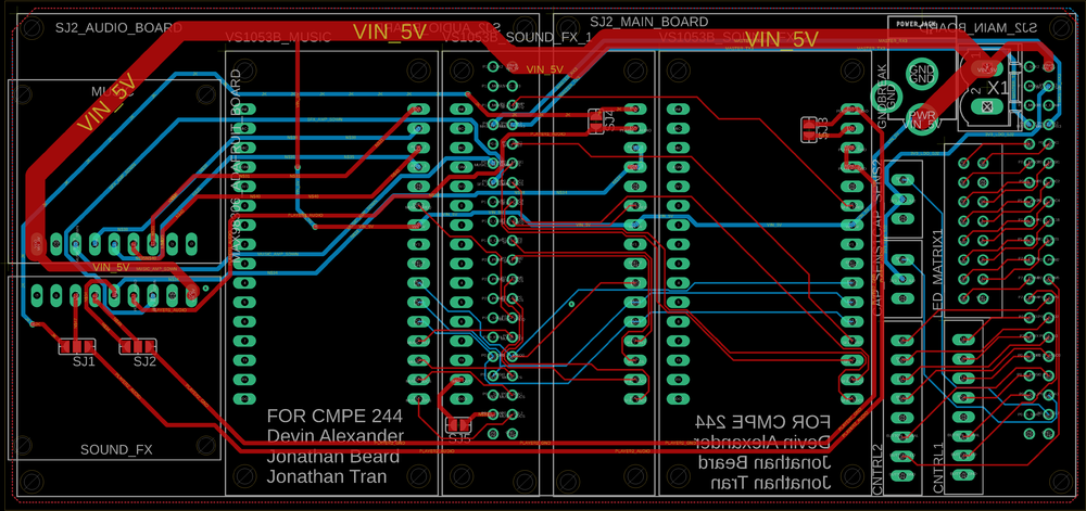
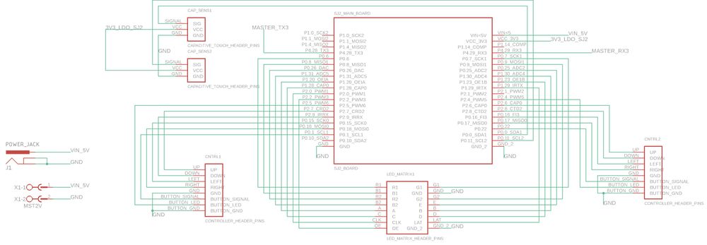
| − | [[File:Space Rage | + | [[File:Space Rage Schematic Main Board.jpg|thumb|center|1000px|'''Main SJ2 Board: This is the schematic for the connections of what we label the Master MCU. This schematic contains connections to the master MCU, the UART bus that we are using to talk to the slave SJ2 audio board, both Controllers that we are using, the LED Matrix Display, and capacitive touch sensor breakouts. Also pictured to the left is the two power connectors that we routed onto the board, one for providing a 4.5V power bus from a wall wart power supply and the other for distributing the 4.5V power bus to the LED Matrix''']] |
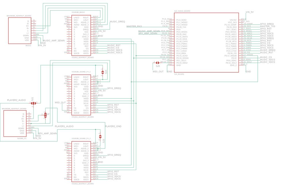
| − | + | [[File:Space Rage Schematic Music.jpg|thumb|center|1000px|'''Audio SJ2 Board: This is the schematic for the connections of what we label the Slave MCU. This portion of the schematic contains connections to the master MCU, three VS1053 MP3 Decoder breakout boards, two MAX98306 stereo amplifier breakout boards, and the UART bus that we are using to talk to the main SJ2 board.''']] | |
| − | + | [[File:Space Rage PCB Layout 450 DPI.png|thumb|center|1000px|'''Here is the Layout. The areas where each breakout board is attached to is clearly marked in outlines with text that resides on the silk screen layer to help show where each of the boards go. Everything from both portions of the schematic fits within the boundaries of this board.''']] | |
| − | |||
| − | + | [[File:Space Rage PCB stack.JPG|thumb|center|1000px|'''Here is the PCB all assembled with the breakout boards that were used on the top and the two SJ2 boards mounted to the bottom. As discussed, the two boards are staggered in heigh from the PCB with the Audio board (left) being spaced 12mm from the PCB and the main SJ2 board (right) is mounted 24mm below the PCB. This allows for both serial programmers to be available to each board at the same time and eliminates the need to unplug and re-plugin the main SJ2 board each time we want to reflash the board.''']] | |
| − | The display for Space Rage is a SparkFun 64x64 RGB LED Matrix. It has a scan rate of 1/32, where 2 of 64 rows are displayed at a single time. The matrix is split into two display sections, a top half and a bottom half such that 1 row of each section is driven at a single time. Due to the speed at which the matrix | + | ==='''LED Matrix'''=== |
| + | |||
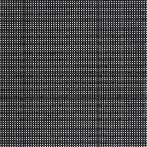
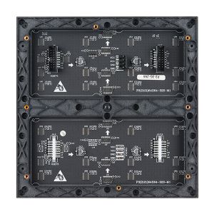
| + | The display for Space Rage is a SparkFun 64x64 RGB LED Matrix. It has a scan rate of 1/32, where 2 of 64 rows are displayed at a single time. The matrix is split into two display sections, a top half and a bottom half such that 1 row of each section is driven at a single time. Due to the speed at which the matrix displays each row, users see an image as a whole due to "persistence of vision". | ||
As the display is split into two sections, rows 0 to 31 are considered to be a part of the upper section and rows 32 to 63 are part of the bottom half of the display. To select a row, the matrix consists of a 5:32 decoder to select each row of the display. This decoder is controlled by the signals A,B,C,D,E. The decoder simultaneously selects the same row in each display, hence each half of the display has rows 0 to 31. | As the display is split into two sections, rows 0 to 31 are considered to be a part of the upper section and rows 32 to 63 are part of the bottom half of the display. To select a row, the matrix consists of a 5:32 decoder to select each row of the display. This decoder is controlled by the signals A,B,C,D,E. The decoder simultaneously selects the same row in each display, hence each half of the display has rows 0 to 31. | ||
To set each pixel color value for each column, the matrix has a shift register to store each 3-bit color value per pixel for 64 columns. As the display is split into two sections, the signals R1,G1,B1 control the upper half of the display and R2,G2,B2 control the bottom half of the display. Thus, each pixel values per display section must be clocked into the shift register using their respective R,G,B signals and are clocked in using the "CLK" signal. Therefore, 64 3-bit values must be clocked into the shift register to store the color value of each pixel of all 64 columns of the display. | To set each pixel color value for each column, the matrix has a shift register to store each 3-bit color value per pixel for 64 columns. As the display is split into two sections, the signals R1,G1,B1 control the upper half of the display and R2,G2,B2 control the bottom half of the display. Thus, each pixel values per display section must be clocked into the shift register using their respective R,G,B signals and are clocked in using the "CLK" signal. Therefore, 64 3-bit values must be clocked into the shift register to store the color value of each pixel of all 64 columns of the display. | ||
| + | |||
| + | <br/> | ||
| + | {| | ||
| + | |[[File:Spark_fun_64x64_rgb_led_matrix.jpg | thumb|300px| left| '''64x64 RGB LED MATRIX FRONT''']] | ||
| + | | | ||
| + | |[[File:CmpE244_F19_T4_Matrix_picture_back.jpg | thumb|300px| left| '''64x64 RGB LED MATRIX BACK''']] | ||
| + | |} | ||
| + | {| | ||
| + | |[[File:space_invaders_diagram_led_matrix.jpg|500px|thumb|left|''' LED MATRIX LAYOUT. (Source: [http://socialledge.com/sjsu/index.php/F20:_Space_Invaders SPACE INVADERS])]] | ||
| + | |} | ||
| + | |||
| + | {| class="wikitable" | ||
| + | |- | ||
| + | ! scope="col"| Matrix PIN Name | ||
| + | ! scope="col"| PIN Description | ||
| + | ! scope="col"| SJ2 Pin Connection | ||
| + | |- | ||
| + | ! scope="row"| A | ||
| + | | Decoder Row Select | ||
| + | | P1.20 | ||
| + | |- | ||
| + | ! scope="row"| B | ||
| + | | Decoder Row Select | ||
| + | | P1.30 | ||
| + | |- | ||
| + | ! scope="row"| C | ||
| + | | Decoder Row Select | ||
| + | | P1.28 | ||
| + | |- | ||
| + | ! scope="row"| D | ||
| + | | Decoder Row Select | ||
| + | | P1.23 | ||
| + | |- | ||
| + | ! scope="row"| E | ||
| + | | Decoder Row Select | ||
| + | | P0.25 | ||
| + | |- | ||
| + | ! scope="row"| R1 | ||
| + | | Upper display red for shift register | ||
| + | | P0.6 | ||
| + | |- | ||
| + | ! scope="row"| G1 | ||
| + | | Upper display green for shift register | ||
| + | | P0.7 | ||
| + | |- | ||
| + | ! scope="row"| B1 | ||
| + | | Upper display blue for shift register | ||
| + | | P0.8 | ||
| + | |- | ||
| + | ! scope="row"| R2 | ||
| + | | Lower half display red for shift register | ||
| + | | P0.26 | ||
| + | |- | ||
| + | ! scope="row"| G2 | ||
| + | | Lower half display green for shift register | ||
| + | | P0.9 | ||
| + | |- | ||
| + | ! scope="row"| B2 | ||
| + | | Lower half display blue for shift register | ||
| + | | P1.31 | ||
| + | |- | ||
| + | ! scope="row"| CLK | ||
| + | | Signal to clock in 3-bit color values per pixel into shift register | ||
| + | | P2.0 | ||
| + | |- | ||
| + | ! scope="row"| LAT | ||
| + | | Signal to latch shift register pixel values to output driver | ||
| + | | P1.29 | ||
| + | |- | ||
| + | ! scope="row"| OE | ||
| + | | Active low signal to output a row's pixels onto display | ||
| + | | P2.2 | ||
| + | |- | ||
| + | |} | ||
| + | |||
| + | ==== Led Display Matrix Software Design ==== | ||
''' How to display a frame ''' | ''' How to display a frame ''' | ||
| − | + | ||
| − | Now given a brief description of the display, the following steps must take place to display a whole frame: | + | Now given a brief description of the display, we will discuss how to display images. A [https://www.sparkfun.com/news/2650 sparkfun] article goes into how RGB Panels work, but here are the following steps that must take place to display a whole frame: |
# Set the R1,G1,B1 and R2,G2,B2 signals to set the desired pixel color for both the upper and bottom display sections | # Set the R1,G1,B1 and R2,G2,B2 signals to set the desired pixel color for both the upper and bottom display sections | ||
# Set "CLK" high to clock in the pixel color for the columns for both display sections simultaneously | # Set "CLK" high to clock in the pixel color for the columns for both display sections simultaneously | ||
| Line 342: | Line 424: | ||
# Disable latch (to clock in the next data). Enable output enable (set low as it is active low) to output the pixels onto the display | # Disable latch (to clock in the next data). Enable output enable (set low as it is active low) to output the pixels onto the display | ||
# Disable output enable after a given delay | # Disable output enable after a given delay | ||
| − | # Repeat above steps until allows rows have been display to display a single frame | + | # Repeat above steps until allows rows have been display to display a single frame |
| − | {| | + | '''Initializing GPIO Pins''' |
| − | |[[File: | + | <br/> |
| − | |[[File: | + | As the 64x64 matrix is controlled by GPIO pins, a function was created to initialize gpio pins for all 14 pins of the matrix. A struct called "led_display_gpio_pins" was created to store multiple port and pin mappings (gpio_s structs) of each pin corresponding to the LED matrix. This allows easier readability on what pins correspond to each LED matrix pin. For instance, led_display_pins.r1 is a struct which has a member 'r1' which is a gpio_s struct which holds the port and pin which is connected to R1 on the LED matrix. |
| + | |||
| + | '''Matrix Representation in a 64x64 Array''' | ||
| + | <br/> | ||
| + | A static 64x64 uint8_t array is used to store the pixel color values of each row and column. Given that colors are controlled by R,G,and B pins, the array can store a value from 0-to-7 to represent a color. A function called led_display__draw_pixel(uint8_t row, uint8_t column, pixel_color_e pixel_color) was given to allow different functions to set certain pixels in the frame. Thus an image can be created by setting multiple pixel colors in the array. | ||
| + | |||
| + | {| class="wikitable" | ||
| + | |- | ||
| + | ! scope="col"| RGB Binary Representation | ||
| + | ! scope="col"| Pixel Color | ||
| + | |- | ||
| + | ! scope="row"| 000 | ||
| + | | Black | ||
| + | |- | ||
| + | ! scope="row"| 001 | ||
| + | | Blue | ||
| + | |- | ||
| + | ! scope="row"| 010 | ||
| + | |Green | ||
| + | |- | ||
| + | ! scope="row"| 011 | ||
| + | | Cyan | ||
| + | |- | ||
| + | ! scope="row"| 100 | ||
| + | | Red | ||
| + | |- | ||
| + | ! scope="row"| 101 | ||
| + | | Purple | ||
| + | |- | ||
| + | ! scope="row"| 110 | ||
| + | | Yellow | ||
| + | |- | ||
| + | ! scope="row"| 111 | ||
| + | | White | ||
| + | |- | ||
| + | |} | ||
| + | |||
| + | '''Display Driver Task''' | ||
| + | <br/> | ||
| + | To drive the display, a task with the highest priority was created to set the corresponding pins on the RGB LED matrix. Whenever the task is running, it loops through all indices of the multi-dimensional array and sets the corresponding R,G,B pins given the value in each index of the array. This is done by following the steps above under '''"How to display a frame"'''. The less time the display driver spends sleeping, the brighter the RGB panel display is. Thus, we had settled for a high frame rate by having the display driver run every 2ms. | ||
| + | |||
| + | === Music, Sound, and Volume Control === | ||
| + | ==== Hardware Interface ==== | ||
| + | ''' MP3 Decoder ''' | ||
| + | <br/> | ||
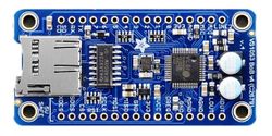
| + | The MP3 decoder boards that we used for this project is a breakout board that can be found on Adafruit.com and utilizes the VS1053b which can decode MP3, playback WAV files, and work with other popular audio formats. for our purposes, we used this for decoding MP3 files. | ||
| + | |||
| + | To both be able to play music and sound effects, we had decided to use more than one MP3 Decoder. In addition, we also wanted each player to have their own sound effects and speaker. Thus, we had opted to use three MP3 Decoders. two MP3 decoders were used for each player and one dedicated to music. As a result of having three MP3 decoders and limited pins on the SJ2 board, we had opted to use a second SJ2 board to serve as the dedicated music board. Thus, we have the SJ2 board which drives the game called "SJ2 Main" and the music board called "SJ2 Music". | ||
| + | |||
| + | To play music and sound effects, the SJ2 Main board sends a command to SJ2 Music over UART. Depending on the command, SJ2 Music will play music or a sound effect through one of the three MP3 decoders. The player one mp3 decoder is denoted as "SOUND_FX1", player two mp3 decoder is denoted as "SOUND_FX2", and finally the music decoder is denoted as "MUSIC". SJ2 Music receives all UART commands using the uart__get() function given by Preet's uart driver and the same same driver is used by SJ2 Main for uart__put() to send a command. | ||
| + | |||
| + | {| | ||
| + | |[[File:VS1053b MP3 Decoder Board.jpg|thumb|left|250px|'''VS1053b MP3 Decoder]] | ||
| + | |} | ||
| + | |||
| + | ''' Stereo Amplifier ''' | ||
| + | |||
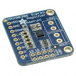
| + | The stereo amplifier breakout boards that we used can also be found on Adafruit.com and utilize the MAX98306, which is a stereo 37w class d audio amplifier IC from Maxim Integrated. | ||
| + | |||
| + | {| | ||
| + | |[[File:MAX98306 breakout board.jpg|250px|thumb|left|'''MAX98306 Stereo Amplifier ]] | ||
| + | |} | ||
| + | |||
| + | ''' Touch Sensor and Volume Control ''' | ||
| + | |||
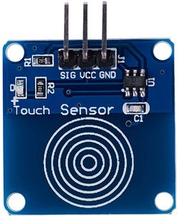
| + | The captive touch button that we used for controlling the volume was fond off of Amazon and is pictured below: | ||
| + | {| | ||
| + | |[[File:Capacitive touch button.jpg|250px|thumb|left|'''Capacitive Touch Button ]] | ||
| + | |} | ||
| + | |||
| + | ==== Software Design ==== | ||
| + | |||
| + | '''Playing three MP3 files concurrently''' | ||
| + | |||
| + | To play up to 3 different MP3 files at the same time using the three separate MP3 decoders, we had to read 3 separate files from SD cards. The route we ended using was to use a singular SD card on the SSP2 bus and all three MP3 decoders were connected on the SSP0 bus. We implemented the SPI drivers for the SD card side using the SSP2 drivers that were provided to us and commands for the FAT file system. For the MP3 decoder side of the drivers, we modified the provided SSP2 driver and made it work with SSP0 by changing a few lines of code. | ||
| + | |||
| + | To read three mp3 files at the same time on an SD card, we set up three separate tasks that would take the file descriptor that was requested to play and we would use a semaphore to block access to the SSP2 bus whenever there was another buffer that needed to be loaded into program memory. After each buffer would be read, we would relinquish the semaphore to the SSP2 line so that any other MP3 decoder that was requesting new buffers to be loaded into it would be able to take the semaphore and have a chance to load its next buffer. After the buffer was loaded into memory, there would be a request to take another semaphore for the SSP0 bus which was used for communications between MP3 boards. After the semaphore was in possession, we then could transfer over the buffer of 32 bytes of data to the MP3 board that was requesting more data. | ||
| + | |||
| + | We would know that an MP3 decoder was in need of more information because we set up polling of the DREQ pins on the VS1053b from the MP3 decoder breakout boards. The pin DREQ is responsible for informing the host MCU that there needs to be more data sent over whenever the internal FIFO is no longer full. Whenever an MP3 file was done playing, we would close out the file from being read. | ||
| + | |||
| + | '''Changing volume''' | ||
| + | |||
| + | To change the volume on the MP3 decoder, we needed to write a value from 0-255 to register 0x0B using the SCI interface. A value of 0 corresponds to no volume attenuation, while a value of 255 corresponds to completely off. The value between each number is 0.5 decibels, so if you wrote a value of 6 for each left and right channel, it would lower the output of both channels by 3dB. | ||
| + | |||
| + | We decided that for the sound effects, we wanted them to be louder than the background music, so we set the volumes of the Music MP3 decoder to a higher offset than the Sound_FX boards, which resulted in roughly a 9dB volume differential between the two devices. | ||
| + | |||
| + | === Player Joysticks and Buttons === | ||
| + | ==== Hardware Interface ==== | ||
| + | For our game, we had decided to have two players. Each player has their own arcade joystick and a button to select a game mode and to use in-game. The arcade controllers have 4 directions, although there is an 8 direction mode, we had opted for only 4 directions. | ||
| + | |||
| + | The joystick has 5-pinout connections. One for each direction and a single GND pin. The button has a 3-pin connection: signal, VCC, and GND. We had connected the Vcc connections to a gpio pin which would allow us to control when the button LED is on and to show that the game is ready for input. However, we had not implemented this logic, and simply left the gpio pins high to have the LEDs always active. | ||
| + | |||
| + | {| | ||
| + | |[[File:Sj2_player_controllers.jpg | thumb|950px| '''SJ2 Board interface to Player Controllers''']] | ||
| + | |} | ||
| + | |||
| + | ''' Cat5e Cable and Player Controllers Interface ''' | ||
| + | <br/> | ||
| + | |||
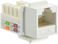
| + | Given the fact that we were dealing with 8 pins in total for each arcade controller and button, we had decided to wire each controller to our PCB using a Cat5e female connector and a Cat5e/Cat6 ethernet cable. This was possible as Cat5e ethernet cables have 8 wires. Our arcade box has two female Cat5e connectors, one for each player. Within the arcade box, wires are connected from the PCB to the female connectors. The same is done for our casing for the arcade controllers and buttons for each player. Therefore, each controller is able to connect to the arcade box by connecting a Cat5e/Cat6 cable to the respective female connectors. However, there is an issue with input delay given the Cat5e/Cat6 ethernet cable length. We have found that 3 to 6ft cables function properly whereas a 15ft cable had noticeable delays and issues. | ||
| + | |||
| + | {| | ||
| + | |[[File:Cat5e_female_connectors.jpg | thumb|200px| '''Cat5e Female Connector''']] | ||
|} | |} | ||
| − | ==== | + | ==== Software Design ==== |
| + | The player controllers are handled by 10 ISRs, 8 for each of the players direction inputs from the controllers, and 2 for each player button. Two queues were created for each player that receives enum values corresponding to a direction. The queues were given a size of 1 to handle the event of switch debounce. Two binary semaphores were also created to handle button input for each player. We had also designed functions to empty the queues and semaphores as the game transitions to different game states in which stale queue values and semaphores are removed. | ||
| − | + | Although two ISRs were created for each player button, we had also polled the player buttons during in-game mode. The reason behind this is due to the fact that "Turbo Mode" in our game relies on the user constantly holding the button. | |
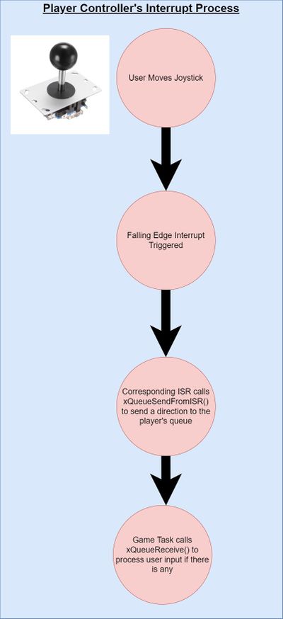
| + | ''' Interrupt Service Routines, FreeRTOS Queues, and User Controller Input Logic: ''' | ||
| + | # Player moves analog controller | ||
| + | # ISR runs and calls xQueueSendsFromISR() a value corresponding to the direction | ||
| + | # Game logic calls function receive_user_input() which calls xQueueReceives() with a 0 timeout to get the direction | ||
| + | # Game logic uses the direction value to make a movement | ||
| − | + | ''' Interrupt Service Routines, FreeRTOS Binary Semaphore, and User Button Input Logic: ''' | |
| + | # Player pushes button during menu select | ||
| + | # ISR runs and calls xSemaphoreGiveFromISR() | ||
| + | # Game logic calls function receive_user_button_input() which calls xSemaphoreTake() with a 0 timeout | ||
| + | # If xSemaphoreTake() returns true, an action such as selecting game mode is done to change the state of the game state machine | ||
| − | === Software Design === | + | {| |
| + | |[[File:Joystick_interrupt_processing.jpg | thumb|400px| '''Player's Joystick Input Processing''']] | ||
| + | |[[File:Button_interrupt_processing.jpg | thumb|400px| '''Player's Button Input Processing''']] | ||
| + | |} | ||
| + | |||
| + | === Game Software Design === | ||
Show your software design. For example, if you are designing an MP3 Player, show the tasks that you are using, and what they are doing at a high level. Do not show the details of the code. For example, do not show exact code, but you may show psuedocode and fragments of code. Keep in mind that you are showing DESIGN of your software, not the inner workings of it. | Show your software design. For example, if you are designing an MP3 Player, show the tasks that you are using, and what they are doing at a high level. Do not show the details of the code. For example, do not show exact code, but you may show psuedocode and fragments of code. Keep in mind that you are showing DESIGN of your software, not the inner workings of it. | ||
| − | ====== | + | ====== Core Game Design ====== |
The game logic runs on a tick system, updating the players location after a certain amount of ticks has passed. | The game logic runs on a tick system, updating the players location after a certain amount of ticks has passed. | ||
A few key attributes are required for the logic of the game to work: | A few key attributes are required for the logic of the game to work: | ||
| Line 369: | Line 568: | ||
**New direction represents the input from the player to change directions after their tick count has reached zero. As a rule, the input will be ignored if the player attempts to go backwards directly onto their drawn trail. | **New direction represents the input from the player to change directions after their tick count has reached zero. As a rule, the input will be ignored if the player attempts to go backwards directly onto their drawn trail. | ||
| − | ====== | + | ====== Game Controller State Machine ====== |
[[file:SpaceRageGameControllerStateMachine.jpg | thumb|450px| center| ''' Game State Machine''']] | [[file:SpaceRageGameControllerStateMachine.jpg | thumb|450px| center| ''' Game State Machine''']] | ||
| Line 389: | Line 588: | ||
When the player is ticked twice (while not holding the button in turbo mode and all the time in classic mode) the game controller will set the new direction for the player. If this new direction would send the player into a wall, the player is considered to have crashed. Once this happens the game state will change to the Lives Screen, where the remaining lives of the player are presented. | When the player is ticked twice (while not holding the button in turbo mode and all the time in classic mode) the game controller will set the new direction for the player. If this new direction would send the player into a wall, the player is considered to have crashed. Once this happens the game state will change to the Lives Screen, where the remaining lives of the player are presented. | ||
| − | ====== | + | ====== AI logic ====== |
There are three main functions utilized as shown: | There are three main functions utilized as shown: | ||
| Line 398: | Line 597: | ||
The hard computer uses a state machine to commence it's attack. It starts by cutting directly down from the top left corner to the bottom right corner, making near impossible turns to cut the board perfectly in half. Once the opponent is either 25 pixels above (or greater) or 25 pixels to the left (or greater) of the player, the computer will either head directly east or directly south, respectively, to cut down the size of the arena. The original intention was to then have the bot simply go to the larger area and survive, since it can play nearly perfectly. This still does happen occasionally, but in certain circumstances the bot will turn into the area where the other player is. This results in rather intense competition. The adjustments were going to be made to ensure just the perfect play would take place, but after testing with the current state, it was found to be more fun to have the bot take either path, as it was much more unpredictable. | The hard computer uses a state machine to commence it's attack. It starts by cutting directly down from the top left corner to the bottom right corner, making near impossible turns to cut the board perfectly in half. Once the opponent is either 25 pixels above (or greater) or 25 pixels to the left (or greater) of the player, the computer will either head directly east or directly south, respectively, to cut down the size of the arena. The original intention was to then have the bot simply go to the larger area and survive, since it can play nearly perfectly. This still does happen occasionally, but in certain circumstances the bot will turn into the area where the other player is. This results in rather intense competition. The adjustments were going to be made to ensure just the perfect play would take place, but after testing with the current state, it was found to be more fun to have the bot take either path, as it was much more unpredictable. | ||
| − | |||
| − | |||
| − | |||
== Testing & Technical Challenges == | == Testing & Technical Challenges == | ||
| − | |||
| − | |||
| − | |||
| − | |||
=== Main Suggestions === | === Main Suggestions === | ||
Make sure you write modular code. Keep functions short and simple to start. The most used function in our project was the function to write to the 64x64 array that represented our display: led_display__draw_pixel. With this simple interface between the LED matrix and the rest of the code allowed for other functions to be written to take care of drawing images of different sizes easily. | Make sure you write modular code. Keep functions short and simple to start. The most used function in our project was the function to write to the 64x64 array that represented our display: led_display__draw_pixel. With this simple interface between the LED matrix and the rest of the code allowed for other functions to be written to take care of drawing images of different sizes easily. | ||
| Line 421: | Line 613: | ||
== Conclusion == | == Conclusion == | ||
| − | + | Throughout the implementation project, we found that we had utilized many concepts that we had learned from this course. The concepts taught in the weeks leading up to the project allowed for us to be prepared to apply them into building Space Rage. The concept of multi-threaded code was newer to some of us, but we feel that it prepares us for our future careers as embedded software engineers. The use of prioritizing various blocks of code over others and how the impacts it has on the scheduling of tasks is an important concept to understand. The knowledge gained from going through the process of debugging the various issues we had experienced along the way will serve as a good building block moving forward in our careers. | |
=== Project Video === | === Project Video === | ||
| Line 431: | Line 623: | ||
== References == | == References == | ||
=== Acknowledgement === | === Acknowledgement === | ||
| − | + | We would like to thank Preet for making a wonderful course which encourages learning over pure memorization. All member of this group project are aiming to pursue careers in embedded systems and all of the knowledge we have gained from this course have been helpful in us reaching those goals. | |
| − | |||
| − | |||
| − | |||
=== Appendix === | === Appendix === | ||
| − | You | + | #[https://www.sparkfun.com/news/2650 Everything You Didn't Want to Know About RGB Matrix Panels] |
Latest revision as of 02:43, 27 August 2022
Contents
SPACE RAGE
Abstract
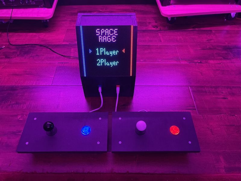
Space Rage was modeled off of the Tron Light Cycle game, in which two players, attempt to have the opponent run into their trail that is left behind as they move. It is similar to Snake, but the trail left behind is not dependent on any pickups and it is competitive. The players are able to move in the cardinal directions, North, East, South, and West, and are not able to steer directly behind them to prevent instant defeat.
There are two levels of AI a player make compete against: Normal and Hard. The difficult of the AI is dependent on which controller the player is using: Player 1 faces the Normal computer while Player 2 faces the Hard computer. The selection of game type is done from the main screen that shows 1 Player or 2 Player. After the selection, the players are free to choose normal mode or turbo. Turbo mode allows for the pressing of the button on the controller to allow the player to move faster.
The display is a 64 by 64 LED matrix. The player controls their ship by using the joystick and button in the controller. The button located on controller allows the user to select options from the main menu and go turbo mode while in that game mode. There are four speakers for the cabinet: two to play music on either side, one for sound effects related to player one, and one for sound effects related to player two. The volume of the speakers is controlled by a touch sensor that is attached to conductive tape which is attached to the side of the cabinet.
Objectives & Introduction
Space Rage is a two player game that tests the players reaction times and strategy in a fast paced arena similar to the Tron Light Cycle game. The players only means of defense and offence is the wall that is left behind them as they move. There were a few key objectives and features we wanted to implement into our game to make it feel more like an arcade game:
- Single Player and Two Player modes
- Sound and Music
- Fast responsive controls
- High activity and quick rounds
Player Modes
The biggest highlight of the game is the two player aspect of the game, allowing you and a friend to play against each other in the game. Each player can use a one of the controllers attached by a CAT5e cable to the main cabinet. There is also a single player mode that allows a player to play an AI driven computer opponent. The difficulty of the computer depends on which player port the player is connected to. This is a nod to old Atari games that had different settings depending on which controller port the user plugged the controller into.
Sound and Music
When we think of arcade games, the thought of immersive visuals is almost just as important as the sound design. For this project, we wanted to set ourselves apart with the sound design section of this project and use 3 MP3 decoders to offer immersive sound on 4 speakers(2 dedicated to stereo background music and the other 2 for sound effects one left and right channel for player 1 and 2 respectively). We opted to do this instead of using a singular MP3 decoder because if we did this option, we could have only played a single MP3 file at a time (either music or a sound effect) but not both concurrently. With the music not taking any breaks to play sound effects, the result of this was a more immersive playing experience. With proper timing of the sound effects, this would only help amplify how immersive it is if the sounds would line up within +/- 20 milliseconds of an appropriate event happening.
Fast responsive controls
We have constructed two arcade joystick pads for each of the two players which are wired to the arcade box. Although the controllers are wired, they have been tested to function properly for up to a 6ft cable. The controllers responsiveness are fast which is desired for a game such as Space Rage which is dependent on strategy and reaction time. The controllers are connected using a cat5e/cat6 cable and can be easily removed for easy transportation.
High activity and quick rounds
We tried to maximize the game space for the game with the limitation of having such a small screen, the 64 x 64 LED matrix. To accommodate this we elected to have small characters, just 2x3 pixels wide, which allowed for a much larger game space. The game does still run at a fast rate, leading to the short quick rounds we intended. We decided on a lives based system for the game, so players have 3 lives before they have truly lost a game. This information is shown between rounds and are represented by hearts, again maximizing the space and giving a brief reprieve from the action.
Team Members & Responsibilities
- Jonathan Beard Gitlab
- Core game logic
- Animation development
- AI construction
- Jonathan Tran Gitlab
- LED Matrix Interface
- Player Controllers Interface
- Game Logic
- MP3 Decoders
- Devin Alexander Gitlab
- Lead construction and design
- PCB designer
- MP3 Decoders
- Sound Engineer
Schedule
| Week# | Start Date | End Date | Task | Status |
|---|---|---|---|---|
| 1 |
|
|
|
|
| 2 |
|
|
|
|
| 3 |
|
|
|
|
| 4 |
|
|
|
|
| 5 |
|
|
|
|
| 6 |
|
|
|
|
| 7 |
|
|
|
|
| 8 |
|
|
|
|
| 9 |
|
|
|
|
| 10 |
|
|
|
|
Bill of Materials
| Item # | Part | Vendor | Qty | Cost |
|---|---|---|---|---|
| 1 | 64x64 RGB LED Matrix | Sparkfun | 1 | $87.15 |
| 2 | SJTwo Boards | Amazon/SJSU | 2 | $100.00 |
| 3 | Two Player Joystick Bundle | Amazon | 1 | $44.99 |
| 4 | MP3 Decoder (VS1053) | Adafruit | 3 | $75.00 |
| 5 | Audio Amplifier | Adafruit | 2 | $18.00 |
| 6 | Cat5e Female Connectors | Home Depot | 2 | $10.00 |
| 7 | Cat6 3ft Ethernet Cables | Home Depot | 2 | $14.00 |
| 8 | Spray Paint | Home Depot | 2 | $7.00 |
| 9 | 2' x 4' Plywood | Home Depot | 1 | $28.00 |
| 10 | Speakers | Adafruit | 4 | $10.00 |
Design & Implementation
The design section can go over your hardware and software design. Organize this section using sub-sections that go over your design and implementation.
PCB
For the PCB that we designed, we were able to get by with using the first rev of the PCB in the final version of the arcade game. As we continued to grow the scope of the project with additional MP3 decoders and an extra SJ2 board and stereo amplifier board, there was quickly a growing concern with using the free license of Eagle to design the board. This is because with the free version, there is a size limitation of how much space you have to lay out your components. So by carefully placing all of the board's components to not waste too much space to allow all components to fit within the space of 65 x 140 mm.
The board that we designed consisted mostly of a means to interconnect all of the different breakout boards(stereo audio amplifiers and MP3 decoders), LED matrix and the other custom breakouts for controllers to both SJ2 boards. It was designed in such a way that all of the modules could be fitted onto the board the SJ2 boards connecting to it from the underside and the other boards all on the top of the PCB. We figured that it would be best to have the traces for the connections to peripherals by correspond to the area of the PCB that was closest to the corresponding SJ2 board. We layed it out so that only one of the SJ2 boards would have it's micro USB been easily accessible, unless you staggered the height of the boards. Because we had this in mid when doing the layout, we were able to quickly flash, test, and debug any code we wrote without any needs to disassemble anything.
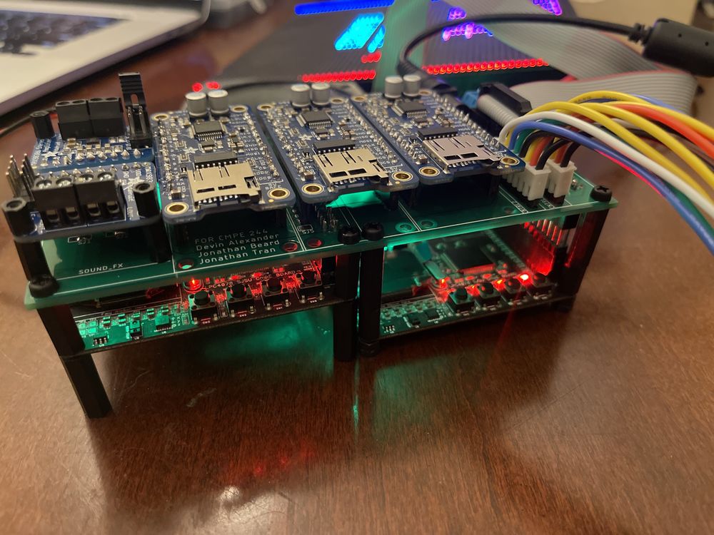
LED Matrix
The display for Space Rage is a SparkFun 64x64 RGB LED Matrix. It has a scan rate of 1/32, where 2 of 64 rows are displayed at a single time. The matrix is split into two display sections, a top half and a bottom half such that 1 row of each section is driven at a single time. Due to the speed at which the matrix displays each row, users see an image as a whole due to "persistence of vision".
As the display is split into two sections, rows 0 to 31 are considered to be a part of the upper section and rows 32 to 63 are part of the bottom half of the display. To select a row, the matrix consists of a 5:32 decoder to select each row of the display. This decoder is controlled by the signals A,B,C,D,E. The decoder simultaneously selects the same row in each display, hence each half of the display has rows 0 to 31.
To set each pixel color value for each column, the matrix has a shift register to store each 3-bit color value per pixel for 64 columns. As the display is split into two sections, the signals R1,G1,B1 control the upper half of the display and R2,G2,B2 control the bottom half of the display. Thus, each pixel values per display section must be clocked into the shift register using their respective R,G,B signals and are clocked in using the "CLK" signal. Therefore, 64 3-bit values must be clocked into the shift register to store the color value of each pixel of all 64 columns of the display.
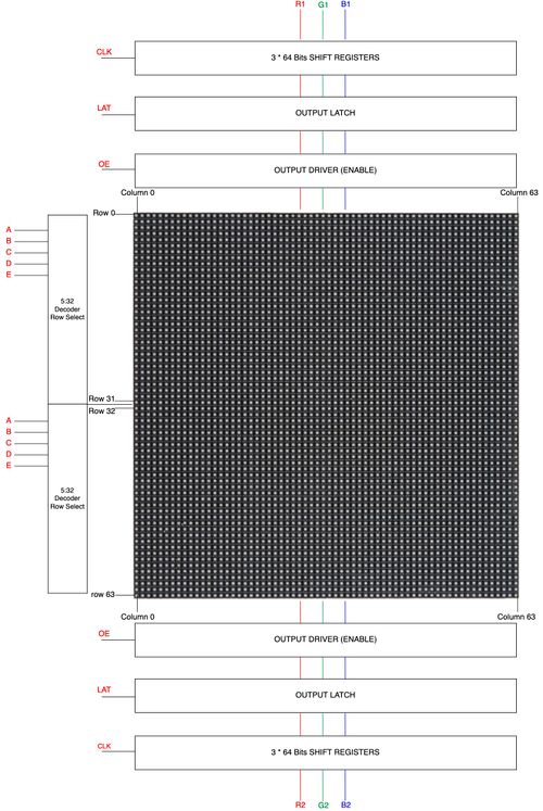 LED MATRIX LAYOUT. (Source: SPACE INVADERS) |
| Matrix PIN Name | PIN Description | SJ2 Pin Connection |
|---|---|---|
| A | Decoder Row Select | P1.20 |
| B | Decoder Row Select | P1.30 |
| C | Decoder Row Select | P1.28 |
| D | Decoder Row Select | P1.23 |
| E | Decoder Row Select | P0.25 |
| R1 | Upper display red for shift register | P0.6 |
| G1 | Upper display green for shift register | P0.7 |
| B1 | Upper display blue for shift register | P0.8 |
| R2 | Lower half display red for shift register | P0.26 |
| G2 | Lower half display green for shift register | P0.9 |
| B2 | Lower half display blue for shift register | P1.31 |
| CLK | Signal to clock in 3-bit color values per pixel into shift register | P2.0 |
| LAT | Signal to latch shift register pixel values to output driver | P1.29 |
| OE | Active low signal to output a row's pixels onto display | P2.2 |
Led Display Matrix Software Design
How to display a frame
Now given a brief description of the display, we will discuss how to display images. A sparkfun article goes into how RGB Panels work, but here are the following steps that must take place to display a whole frame:
- Set the R1,G1,B1 and R2,G2,B2 signals to set the desired pixel color for both the upper and bottom display sections
- Set "CLK" high to clock in the pixel color for the columns for both display sections simultaneously
- Set latch high to allow the data to the output driver (Output enable should be disable. (i.e. set high))
- Set A,B,C,D,E to select the row to display all pixel values of the 64 columns. (Recall we are selecting rows simultaneously in each display section)
- Disable latch (to clock in the next data). Enable output enable (set low as it is active low) to output the pixels onto the display
- Disable output enable after a given delay
- Repeat above steps until allows rows have been display to display a single frame
Initializing GPIO Pins
As the 64x64 matrix is controlled by GPIO pins, a function was created to initialize gpio pins for all 14 pins of the matrix. A struct called "led_display_gpio_pins" was created to store multiple port and pin mappings (gpio_s structs) of each pin corresponding to the LED matrix. This allows easier readability on what pins correspond to each LED matrix pin. For instance, led_display_pins.r1 is a struct which has a member 'r1' which is a gpio_s struct which holds the port and pin which is connected to R1 on the LED matrix.
Matrix Representation in a 64x64 Array
A static 64x64 uint8_t array is used to store the pixel color values of each row and column. Given that colors are controlled by R,G,and B pins, the array can store a value from 0-to-7 to represent a color. A function called led_display__draw_pixel(uint8_t row, uint8_t column, pixel_color_e pixel_color) was given to allow different functions to set certain pixels in the frame. Thus an image can be created by setting multiple pixel colors in the array.
| RGB Binary Representation | Pixel Color |
|---|---|
| 000 | Black |
| 001 | Blue |
| 010 | Green |
| 011 | Cyan |
| 100 | Red |
| 101 | Purple |
| 110 | Yellow |
| 111 | White |
Display Driver Task
To drive the display, a task with the highest priority was created to set the corresponding pins on the RGB LED matrix. Whenever the task is running, it loops through all indices of the multi-dimensional array and sets the corresponding R,G,B pins given the value in each index of the array. This is done by following the steps above under "How to display a frame". The less time the display driver spends sleeping, the brighter the RGB panel display is. Thus, we had settled for a high frame rate by having the display driver run every 2ms.
Music, Sound, and Volume Control
Hardware Interface
MP3 Decoder
The MP3 decoder boards that we used for this project is a breakout board that can be found on Adafruit.com and utilizes the VS1053b which can decode MP3, playback WAV files, and work with other popular audio formats. for our purposes, we used this for decoding MP3 files.
To both be able to play music and sound effects, we had decided to use more than one MP3 Decoder. In addition, we also wanted each player to have their own sound effects and speaker. Thus, we had opted to use three MP3 Decoders. two MP3 decoders were used for each player and one dedicated to music. As a result of having three MP3 decoders and limited pins on the SJ2 board, we had opted to use a second SJ2 board to serve as the dedicated music board. Thus, we have the SJ2 board which drives the game called "SJ2 Main" and the music board called "SJ2 Music".
To play music and sound effects, the SJ2 Main board sends a command to SJ2 Music over UART. Depending on the command, SJ2 Music will play music or a sound effect through one of the three MP3 decoders. The player one mp3 decoder is denoted as "SOUND_FX1", player two mp3 decoder is denoted as "SOUND_FX2", and finally the music decoder is denoted as "MUSIC". SJ2 Music receives all UART commands using the uart__get() function given by Preet's uart driver and the same same driver is used by SJ2 Main for uart__put() to send a command.
Stereo Amplifier
The stereo amplifier breakout boards that we used can also be found on Adafruit.com and utilize the MAX98306, which is a stereo 37w class d audio amplifier IC from Maxim Integrated.
Touch Sensor and Volume Control
The captive touch button that we used for controlling the volume was fond off of Amazon and is pictured below:
Software Design
Playing three MP3 files concurrently
To play up to 3 different MP3 files at the same time using the three separate MP3 decoders, we had to read 3 separate files from SD cards. The route we ended using was to use a singular SD card on the SSP2 bus and all three MP3 decoders were connected on the SSP0 bus. We implemented the SPI drivers for the SD card side using the SSP2 drivers that were provided to us and commands for the FAT file system. For the MP3 decoder side of the drivers, we modified the provided SSP2 driver and made it work with SSP0 by changing a few lines of code.
To read three mp3 files at the same time on an SD card, we set up three separate tasks that would take the file descriptor that was requested to play and we would use a semaphore to block access to the SSP2 bus whenever there was another buffer that needed to be loaded into program memory. After each buffer would be read, we would relinquish the semaphore to the SSP2 line so that any other MP3 decoder that was requesting new buffers to be loaded into it would be able to take the semaphore and have a chance to load its next buffer. After the buffer was loaded into memory, there would be a request to take another semaphore for the SSP0 bus which was used for communications between MP3 boards. After the semaphore was in possession, we then could transfer over the buffer of 32 bytes of data to the MP3 board that was requesting more data.
We would know that an MP3 decoder was in need of more information because we set up polling of the DREQ pins on the VS1053b from the MP3 decoder breakout boards. The pin DREQ is responsible for informing the host MCU that there needs to be more data sent over whenever the internal FIFO is no longer full. Whenever an MP3 file was done playing, we would close out the file from being read.
Changing volume
To change the volume on the MP3 decoder, we needed to write a value from 0-255 to register 0x0B using the SCI interface. A value of 0 corresponds to no volume attenuation, while a value of 255 corresponds to completely off. The value between each number is 0.5 decibels, so if you wrote a value of 6 for each left and right channel, it would lower the output of both channels by 3dB.
We decided that for the sound effects, we wanted them to be louder than the background music, so we set the volumes of the Music MP3 decoder to a higher offset than the Sound_FX boards, which resulted in roughly a 9dB volume differential between the two devices.
Player Joysticks and Buttons
Hardware Interface
For our game, we had decided to have two players. Each player has their own arcade joystick and a button to select a game mode and to use in-game. The arcade controllers have 4 directions, although there is an 8 direction mode, we had opted for only 4 directions.
The joystick has 5-pinout connections. One for each direction and a single GND pin. The button has a 3-pin connection: signal, VCC, and GND. We had connected the Vcc connections to a gpio pin which would allow us to control when the button LED is on and to show that the game is ready for input. However, we had not implemented this logic, and simply left the gpio pins high to have the LEDs always active.
Cat5e Cable and Player Controllers Interface
Given the fact that we were dealing with 8 pins in total for each arcade controller and button, we had decided to wire each controller to our PCB using a Cat5e female connector and a Cat5e/Cat6 ethernet cable. This was possible as Cat5e ethernet cables have 8 wires. Our arcade box has two female Cat5e connectors, one for each player. Within the arcade box, wires are connected from the PCB to the female connectors. The same is done for our casing for the arcade controllers and buttons for each player. Therefore, each controller is able to connect to the arcade box by connecting a Cat5e/Cat6 cable to the respective female connectors. However, there is an issue with input delay given the Cat5e/Cat6 ethernet cable length. We have found that 3 to 6ft cables function properly whereas a 15ft cable had noticeable delays and issues.
Software Design
The player controllers are handled by 10 ISRs, 8 for each of the players direction inputs from the controllers, and 2 for each player button. Two queues were created for each player that receives enum values corresponding to a direction. The queues were given a size of 1 to handle the event of switch debounce. Two binary semaphores were also created to handle button input for each player. We had also designed functions to empty the queues and semaphores as the game transitions to different game states in which stale queue values and semaphores are removed.
Although two ISRs were created for each player button, we had also polled the player buttons during in-game mode. The reason behind this is due to the fact that "Turbo Mode" in our game relies on the user constantly holding the button.
Interrupt Service Routines, FreeRTOS Queues, and User Controller Input Logic:
- Player moves analog controller
- ISR runs and calls xQueueSendsFromISR() a value corresponding to the direction
- Game logic calls function receive_user_input() which calls xQueueReceives() with a 0 timeout to get the direction
- Game logic uses the direction value to make a movement
Interrupt Service Routines, FreeRTOS Binary Semaphore, and User Button Input Logic:
- Player pushes button during menu select
- ISR runs and calls xSemaphoreGiveFromISR()
- Game logic calls function receive_user_button_input() which calls xSemaphoreTake() with a 0 timeout
- If xSemaphoreTake() returns true, an action such as selecting game mode is done to change the state of the game state machine
Game Software Design
Show your software design. For example, if you are designing an MP3 Player, show the tasks that you are using, and what they are doing at a high level. Do not show the details of the code. For example, do not show exact code, but you may show psuedocode and fragments of code. Keep in mind that you are showing DESIGN of your software, not the inner workings of it.
Core Game Design
The game logic runs on a tick system, updating the players location after a certain amount of ticks has passed. A few key attributes are required for the logic of the game to work:
- Each player has a speed (either 2 ticks for slow or 1 tick for fast)
- This speed denotes how many game ticks must occur before the player is moved.
- This tick count is stored in each players' game object.
- Drawn Direction and New Direction
- Drawn direction represents the way the player was facing, used to keep track of what pixels need to be cleared when movement occurs.
- New direction represents the input from the player to change directions after their tick count has reached zero. As a rule, the input will be ignored if the player attempts to go backwards directly onto their drawn trail.
Game Controller State Machine
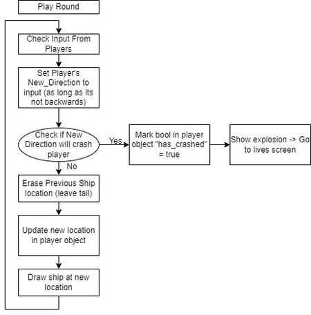
The Game Controller is the state machine that makes the game operate as a whole, with menus, sounds, and input. Each state is simplified in the diagram to its core functionality.
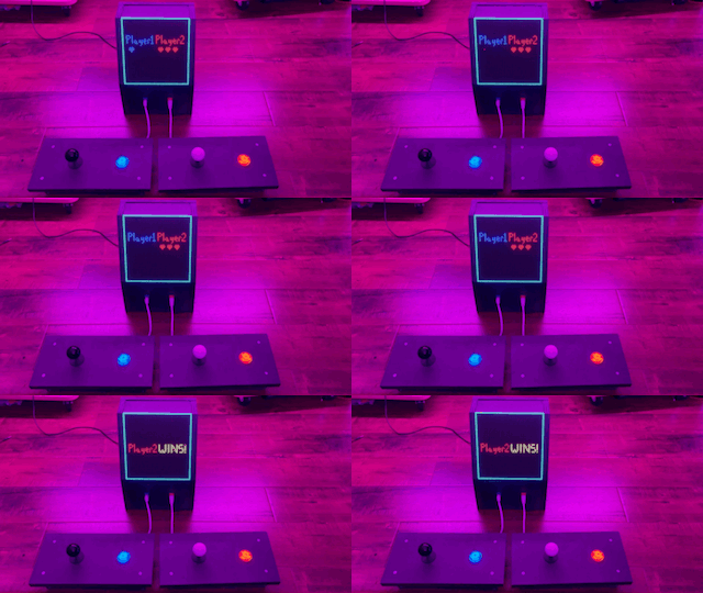
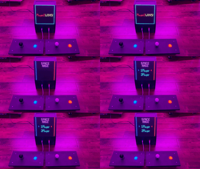
The title screen is the background for both the player select screen and mode select screen, as visible in the main menu screenshots. The user is able to move the joystick up or down in these menus to the choices they want to select, then they hit the button on the controller to accept that choice. Once selections has been made for both menus, the round will begin. The lives screen shows up between rounds and displays how many lives each player has, represented as hearts. When a player crashes the heart is either faded out or faded out then exploded to represent the loss of a life. Once either one or both of the players has lost all 3 lives, the game over screen will display who won or a draw (in the case of both players losing all three lives). Each of these screens, the selections, and the winning player is played out of both of the sound effect speakers, with a slight delay on one to give it the arcade sound effect feel.
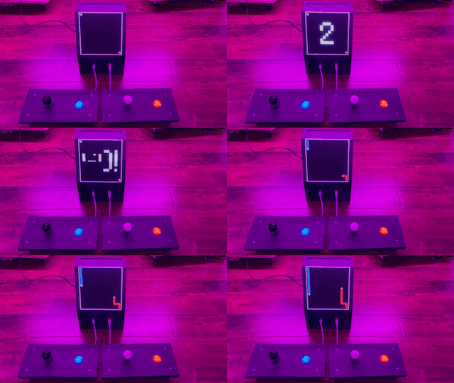
The logic presented here is slightly simplified, but the main components are displayed. At the start of the round the 3,2,1,Go! animation plays to warn the character when the round is about to start. The controls for the player are interrupt driven, putting the direction moved on the joystick into a queue of size 1 for the game controller to interpret. The input is ignored if the player did attempt to go backwards. When the player is ticked twice (while not holding the button in turbo mode and all the time in classic mode) the game controller will set the new direction for the player. If this new direction would send the player into a wall, the player is considered to have crashed. Once this happens the game state will change to the Lives Screen, where the remaining lives of the player are presented.
AI logic
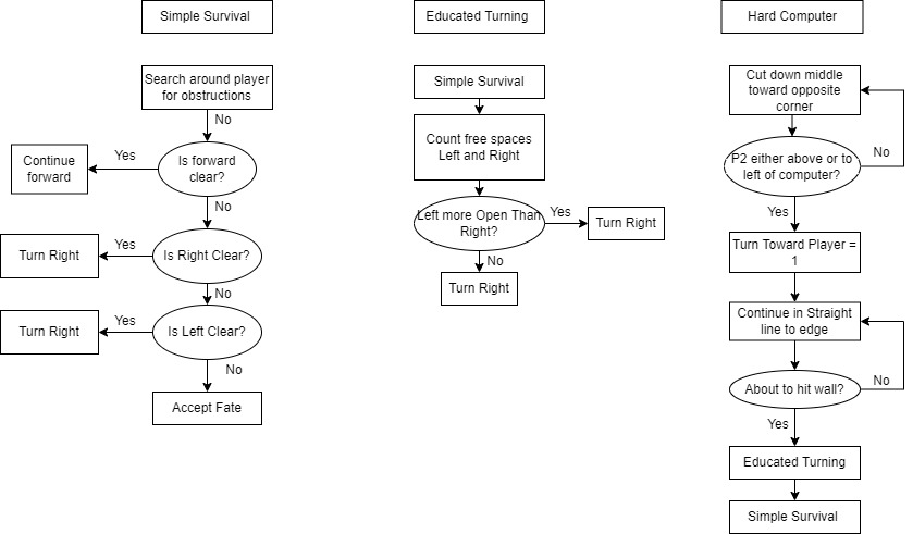
There are three main functions utilized as shown:
The normal computer uses simple survival and educated turning to survive. To make the bot slightly less predictable, the bot has a 3% chance to turn either left or right, based off the educated turning model. This will still likely result in human being able to easily defeat the bot. The major intention on with this difficulty is to allow the player to practice the game without fear of the other player being too aggressive.
The hard computer uses a state machine to commence it's attack. It starts by cutting directly down from the top left corner to the bottom right corner, making near impossible turns to cut the board perfectly in half. Once the opponent is either 25 pixels above (or greater) or 25 pixels to the left (or greater) of the player, the computer will either head directly east or directly south, respectively, to cut down the size of the arena. The original intention was to then have the bot simply go to the larger area and survive, since it can play nearly perfectly. This still does happen occasionally, but in certain circumstances the bot will turn into the area where the other player is. This results in rather intense competition. The adjustments were going to be made to ensure just the perfect play would take place, but after testing with the current state, it was found to be more fun to have the bot take either path, as it was much more unpredictable.
Testing & Technical Challenges
Main Suggestions
Make sure you write modular code. Keep functions short and simple to start. The most used function in our project was the function to write to the 64x64 array that represented our display: led_display__draw_pixel. With this simple interface between the LED matrix and the rest of the code allowed for other functions to be written to take care of drawing images of different sizes easily.
Keeping code simple and using a naming convention that called for a description of what the function was doing allowed for rapid development with little to no debugging required.
AI
Figuring out the logic for a computer opponent in a game such as ours is a difficult task. To figure out how to optimize a bot, you must figure out various strategies the computer should employ and allow the bot to have as much or more knowledge of the game state as a human would have while playing. For our purposes, the simplest of computer difficulties basically plays without knowledge of the opponent's actions. This results in a very easy to trap opponent. Once we added in more knowledge for the AI, a viscous attack strategy was able to be formulated and the bot then took on the elements of a state machine. The initial part of the attack involved getting to the opposite bottom corner as fast as possible, going right down the middle of the screen making humanly impossible turns. Once the bot reached a close enough location to the other player, it would then decide (almost randomly, the algorithm is a bit complex) to either:
- Go to the section of the screen the other player was not in and play a survival game, one a human is likely to lose.
- Or join the player in the section and attempt to survive.
The original intention was to force the bot to take the first option every time, but due the suggestion algorithm not responding exactly as intended, the bot can do either option listed previously. This bug actually made the experience more enjoyable and gave some variance to the bot's play style. The main take away from this section should be that not every not every bug is a fatal error when programming a game. The code was sufficiently tested to reasonably assert than no other crash happens because of the AI decisions.
Conclusion
Throughout the implementation project, we found that we had utilized many concepts that we had learned from this course. The concepts taught in the weeks leading up to the project allowed for us to be prepared to apply them into building Space Rage. The concept of multi-threaded code was newer to some of us, but we feel that it prepares us for our future careers as embedded software engineers. The use of prioritizing various blocks of code over others and how the impacts it has on the scheduling of tasks is an important concept to understand. The knowledge gained from going through the process of debugging the various issues we had experienced along the way will serve as a good building block moving forward in our careers.
Project Video
Project Source Code
References
Acknowledgement
We would like to thank Preet for making a wonderful course which encourages learning over pure memorization. All member of this group project are aiming to pursue careers in embedded systems and all of the knowledge we have gained from this course have been helpful in us reaching those goals.
