Difference between revisions of "S22: Silver Arrow"
(→Sensor ECU : Communication Bridge) |
(→Advice for Future Students) |
||
| (152 intermediate revisions by 2 users not shown) | |||
| Line 1: | Line 1: | ||
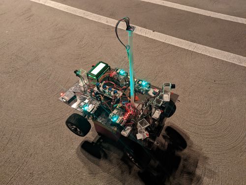
[[File:Silver_arrow.jpg|thumb|800px|caption|middle|Silver Arrow RC]] | [[File:Silver_arrow.jpg|thumb|800px|caption|middle|Silver Arrow RC]] | ||
| + | [[File:CAR MOTION.gif|thumb|1000px|caption|middle|| RC car motion]] | ||
== '''SILVER ARROW''' == | == '''SILVER ARROW''' == | ||
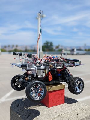
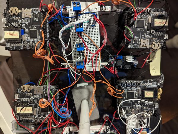
| + | [[File:SACar_top_view.jpg|500px|left|caption|thumb| RC Top View]] [[File:SACar_side_view.jpg|300px|centre|caption|thumb| RC Side View]] | ||
| − | |||
| − | |||
<HR> | <HR> | ||
| Line 24: | Line 24: | ||
=== Team Members & Responsibilities === | === Team Members & Responsibilities === | ||
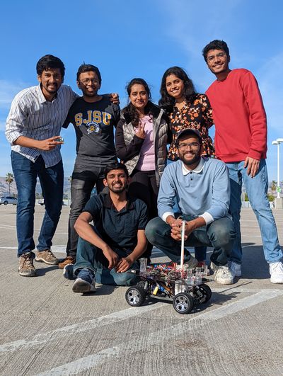
| − | [[File:SATeam_picture.jpg| | + | [[File:SATeam_picture.jpg|400px|middle|center|caption|thumb| Team Photo]] |
''' [https://www.linkedin.com/in/rishabh-gupta-a56ab5125/ Rishabh Gupta]''' | ''' [https://www.linkedin.com/in/rishabh-gupta-a56ab5125/ Rishabh Gupta]''' | ||
* <font color="red">'''Driver Node'''</font> | * <font color="red">'''Driver Node'''</font> | ||
| − | * <font color="red"> '''Compass & GPS | + | * <font color="red"> '''Compass & GPS Calibration'''</font> |
* <font color="red"> '''Waypoint algorithm'''</font> | * <font color="red"> '''Waypoint algorithm'''</font> | ||
| Line 39: | Line 39: | ||
* <font color="violet">'''Sensor controller '''</font> | * <font color="violet">'''Sensor controller '''</font> | ||
* <font color="violet">'''Communication Bridge Controller '''</font> | * <font color="violet">'''Communication Bridge Controller '''</font> | ||
| + | * <font color="violet">'''Hardware and App Integration '''</font> | ||
| − | ''' [https://www.linkedin.com/in/saharshanuragshivhare/ | + | ''' [https://www.linkedin.com/in/saharshanuragshivhare/ Saharsh Shivahre]''' |
* <font color="black">'''Geo controller '''</font> | * <font color="black">'''Geo controller '''</font> | ||
* <font color="black">'''LCD Integration '''</font> | * <font color="black">'''LCD Integration '''</font> | ||
| Line 364: | Line 365: | ||
<BR/> | <BR/> | ||
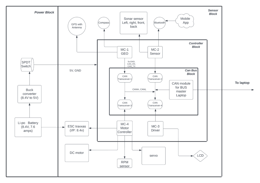
| − | == | + | == Project Design == |
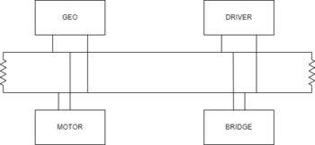
| − | + | [[File:SA_block_diagram.png|900px|caption|center|thumb| System Architecture]] | |
<br> | <br> | ||
| + | [[File:prototype_design.jpg|600px|caption|center|thumb| Prototype Design]] | ||
| + | <br> | ||
| + | |||
<HR> | <HR> | ||
<BR/> | <BR/> | ||
| + | |||
== CAN Communication == | == CAN Communication == | ||
| − | |||
CAN protocol was used to establish the communication between the four controllers. The Message IDs for the messages transmitted by the four controllers were selected such that the data that has to be sampled more often than others had the highest priority in arbitration. | CAN protocol was used to establish the communication between the four controllers. The Message IDs for the messages transmitted by the four controllers were selected such that the data that has to be sampled more often than others had the highest priority in arbitration. | ||
| Line 385: | Line 389: | ||
=== DBC File === | === DBC File === | ||
| − | https://gitlab.com/naveena.sura/silver-arrow/-/blob/MOTORCONTROLLER/dbc/project.dbc | + | [https://gitlab.com/naveena.sura/silver-arrow/-/blob/MOTORCONTROLLER/dbc/project.dbc/ GITlab Project DBC] |
| + | <pre> | ||
| + | VERSION "" | ||
| + | |||
| + | NS_ : | ||
| + | BA_ | ||
| + | BA_DEF_ | ||
| + | BA_DEF_DEF_ | ||
| + | BA_DEF_DEF_REL_ | ||
| + | BA_DEF_REL_ | ||
| + | BA_DEF_SGTYPE_ | ||
| + | BA_REL_ | ||
| + | BA_SGTYPE_ | ||
| + | BO_TX_BU_ | ||
| + | BU_BO_REL_ | ||
| + | BU_EV_REL_ | ||
| + | BU_SG_REL_ | ||
| + | CAT_ | ||
| + | CAT_DEF_ | ||
| + | CM_ | ||
| + | ENVVAR_DATA_ | ||
| + | EV_DATA_ | ||
| + | FILTER | ||
| + | NS_DESC_ | ||
| + | SGTYPE_ | ||
| + | SGTYPE_VAL_ | ||
| + | SG_MUL_VAL_ | ||
| + | SIGTYPE_VALTYPE_ | ||
| + | SIG_GROUP_ | ||
| + | SIG_TYPE_REF_ | ||
| + | SIG_VALTYPE_ | ||
| + | VAL_ | ||
| + | VAL_TABLE_ | ||
| + | |||
| + | BS_: | ||
| + | |||
| + | BU_: DBG DRIVER IO MOTOR SENSOR GEO | ||
| + | |||
| + | |||
| + | BO_ 100 BRIDGE_APP_COMMANDS: 1 SENSOR | ||
| + | SG_ APP_COMMAND : 0|2@1+ (1,0) [0|0] "" GEO,DRIVER | ||
| + | |||
| + | BO_ 101 MOTOR_CHANGE_SPEED_AND_ANGLE_MSG: 2 DRIVER | ||
| + | SG_ DC_MOTOR_DRIVE_SPEED_sig : 0|8@1+ (0.1,-10) [-10|10] "kph" MOTOR | ||
| + | SG_ SERVO_STEER_ANGLE_sig : 8|8@1+ (1,-45) [-45|45] "degrees" MOTOR | ||
| + | |||
| + | BO_ 102 SENSOR_SONARS_ROUTINE: 5 SENSOR | ||
| + | SG_ SENSOR_SONARS_left : 0|10@1+ (1,0) [0|0] "inch" DRIVER | ||
| + | SG_ SENSOR_SONARS_right : 10|10@1+ (1,0) [0|0] "inch" DRIVER | ||
| + | SG_ SENSOR_SONARS_middle : 20|10@1+ (1,0) [0|0] "inch" DRIVER | ||
| + | SG_ SENSOR_SONARS_rear : 30|10@1+ (1,0) [0|0] "inch" DRIVER | ||
| + | |||
| + | BO_ 300 GPS_DESTINATION_LOCATION: 8 SENSOR | ||
| + | SG_ DEST_LATITUDE : 0|32@1+ (0.000001,-90.000000) [-90|90] "Degrees" GEO | ||
| + | SG_ DEST_LONGITUDE : 32|32@1+ (0.000001,-180.000000) [-180|180] "Degrees" GEO | ||
| + | |||
| + | BO_ 301 COMPASS_HEADING_DISTANCE: 6 GEO | ||
| + | SG_ CURRENT_HEADING : 0|12@1+ (0.1,0) [0|359.9] "Degrees" DRIVER,SENSOR | ||
| + | SG_ DESTINATION_HEADING: 12|12@1+ (0.1,0) [0|359.9] "Degrees" DRIVER,SENSOR | ||
| + | SG_ DISTANCE : 24|17@1+ (0.01,0) [0|0] "Meters" DRIVER,SENSOR | ||
| + | |||
| + | BO_ 501 GPS_CURRENT_INFO: 8 GEO | ||
| + | SG_ GPS_CURRENT_LAT : 0|32@1+ (0.000001,-90.000000) [-90|90] "degrees" DRIVER,SENSOR,MOTOR | ||
| + | SG_ GPS_CURRENT_LONG : 32|32@1+ (0.000001,-180.000000) [-180|180] "degrees" DRIVER,SENSOR,MOTOR | ||
| + | |||
| + | BO_ 502 GPS_COMPASS_STATUS : 1 GEO | ||
| + | SG_ COMPASS_LOCK_VALID: 0|1@1+ (1,0) [0|0] "TRUE_FALSE" DRIVER, SENSOR | ||
| + | SG_ GPS_LOCK_VALID : 1|1@1+ (1,0) [0|0] "TRUE_FALSE" DRIVER,SENSOR,MOTOR | ||
| + | |||
| + | BO_ 503 GPS_CURRENT_DESTINATIONS_DATA: 8 GEO | ||
| + | SG_ CURRENT_DEST_LATITUDE : 0|32@1+ (0.000001,-90.000000) [-90|90] "Degrees" DRIVER | ||
| + | SG_ CURRENT_DEST_LONGITUDE : 32|32@1+ (0.000001,-180.000000) [-180|180] "Degrees" DRIVER | ||
| + | |||
| + | BO_ 504 RC_CAR_SPEED_READ_MSG: 2 MOTOR | ||
| + | SG_ RC_CAR_SPEED_sig : 0|8@1+ (0.1,-10) [-10|10] "kph" DRIVER,SENSOR | ||
| + | |||
| + | BO_ 750 DBG_RAW_COMPASS_DATA: 4 GEO | ||
| + | SG_ SIGNED_REGISTER_VAL_MAG_X : 0|16@1+ (1.0,0) [-2048|2047] "GAUSSIAN" DRIVER,SENSOR | ||
| + | SG_ SIGNED_REGISTER_VAL_MAG_Y : 16|16@1+ (1.0,0) [-2048|2047] "GAUSSIAN" DRIVER,SENSOR | ||
| + | |||
| + | BO_ 751 DBG_CONFIRM_RECEIVED_DESTINATION: 8 GEO | ||
| + | SG_ RECEIVED_DEST_LATITUDE : 0|32@1+ (0.000001,-90.000000) [-90|90] "Degrees" SENSOR | ||
| + | SG_ RECEIVED_DEST_LONGITUDE : 32|32@1+ (0.000001,-180.000000) [-180|180] "Degrees" SENSOR | ||
| + | |||
| + | BO_ 775 DBG_GPS_COMPASS_LOCK_LED_CHECK: 1 GEO | ||
| + | SG_ COMPASS_LED_STATUS: 0|1@1+ (1,0) [0|0] "TRUE_FALSE" DRIVER, SENSOR, MOTOR | ||
| + | SG_ GPS_LED_STATUS : 1|1@1+ (1,0) [0|0] "TRUE_FALSE" DRIVER, SENSOR, MOTOR | ||
| + | |||
| + | BO_ 780 DBG_GEO_CAN_STATUS: 3 GEO | ||
| + | SG_ DBG_CAN_INIT_STATUS: 0|1@1+ (1,0) [0|0] "TRUE_FALSE" DRIVER, SENSOR, MOTOR | ||
| + | SG_ DBG_CAN_RX_DROP_COUNT : 1|16@1+ (1,0) [0|0] "TRUE_FALSE" DRIVER,SENSOR,MOTOR | ||
| + | |||
| + | BO_ 781 DBG_SENSOR_CAN_STATUS: 3 SENSOR | ||
| + | SG_ DBG_CAN_INIT_STATUS: 0|1@1+ (1,0) [0|0] "TRUE_FALSE" DRIVER, GEO, MOTOR | ||
| + | SG_ DBG_CAN_RX_DROP_COUNT : 1|16@1+ (1,0) [0|0] "TRUE_FALSE" DRIVER,GEO,MOTOR | ||
| + | |||
| + | BO_ 782 DBG_MOTOR_CAN_STATUS: 3 MOTOR | ||
| + | SG_ DBG_CAN_INIT_STATUS: 0|1@1+ (1,0) [0|0] "TRUE_FALSE" DRIVER, SENSOR, GEO | ||
| + | SG_ DBG_CAN_RX_DROP_COUNT : 1|16@1+ (1,0) [0|0] "TRUE_FALSE" DRIVER,SENSOR,GEO | ||
| + | |||
| + | BO_ 783 DBG_DRIVER_CAN_STATUS: 3 DRIVER | ||
| + | SG_ DBG_CAN_INIT_STATUS: 0|1@1+ (1,0) [0|0] "TRUE_FALSE" GEO, SENSOR, MOTOR | ||
| + | SG_ DBG_CAN_RX_DROP_COUNT : 1|16@1+ (1,0) [0|0] "TRUE_FALSE" GEO,SENSOR,MOTOR | ||
| + | |||
| + | BO_ 784 DBG_MOTOR_INFO_MSG: 4 MOTOR | ||
| + | SG_ DC_MOTOR_CURRENT_PWM _sig: 0|8@1+ (0.1,0) [0|0] "duty percent" DRIVER | ||
| + | SG_ SERVO_MOTOR_CURRENT_PWM_sig : 8|8@1+ (0.1,0) [0|0] "duty percent" DRIVER | ||
| + | SG_ PID_OUTPUT_VALUE_sig : 16|8@1+ (0.1,-10) [0|0] "kph" DRIVER | ||
| + | SG_ MOTOR_SELF_TEST_sig : 24|1@1+ (1,0) [0|0] "TRUE_FALSE" DRIVER | ||
| + | |||
| + | BO_ 001 DRIVER_HEARTBEAT: 1 DRIVER | ||
| + | SG_ DRIVER_HEARTBEAT_cmd : 0|8@1+ (1,0) [0|0] "" SENSOR,MOTOR | ||
| + | |||
| + | BO_ 002 SENSOR_HEARTBEAT: 1 SENSOR | ||
| + | SG_ DRIVER_HEARTBEAT_cmd : 0|8@1+ (1,0) [0|0] "" SENSOR,MOTOR | ||
| + | |||
| + | BO_ 003 GEO_HEARTBEAT: 1 GEO | ||
| + | SG_ DRIVER_HEARTBEAT_cmd : 0|8@1+ (1,0) [0|0] "" SENSOR,MOTOR | ||
| + | |||
| + | BO_ 004 MOTOR_HEARTBEAT_MSG: 1 MOTOR | ||
| + | SG_ MOTOR_HEARTBEAT_sig : 0|8@1+ (1,0) [0|255] "pulse" DRIVER | ||
| + | |||
| + | CM_ BU_ DRIVER "The driver controller driving the car"; | ||
| + | CM_ BU_ MOTOR "The motor controller of the car"; | ||
| + | CM_ BU_ SENSOR "The sensor controller of the car"; | ||
| + | CM_ BO_ 100 "Sync message used to synchronize the controllers"; | ||
| + | CM_ SG_ 100 DRIVER_HEARTBEAT_cmd "Heartbeat command from the driver"; | ||
| + | |||
| + | BA_DEF_ "BusType" STRING ; | ||
| + | BA_DEF_ BO_ "GenMsgCycleTime" INT 0 0; | ||
| + | BA_DEF_ SG_ "FieldType" STRING ; | ||
| + | |||
| + | BA_DEF_DEF_ "BusType" "CAN"; | ||
| + | BA_DEF_DEF_ "FieldType" ""; | ||
| + | BA_DEF_DEF_ "GenMsgCycleTime" 0; | ||
| + | |||
| + | BA_ "GenMsgCycleTime" BO_ 100 1000; | ||
| + | BA_ "GenMsgCycleTime" BO_ 200 50; | ||
| + | BA_ "FieldType" SG_ 100 DRIVER_HEARTBEAT_cmd "DRIVER_HEARTBEAT_cmd"; | ||
| + | |||
| + | VAL_ 100 DRIVER_HEARTBEAT_cmd 2 "DRIVER_HEARTBEAT_cmd_REBOOT" 1 "DRIVER_HEARTBEAT_cmd_SYNC" 0 "DRIVER_HEARTBEAT_cmd_NOOP" ; | ||
| + | </pre> | ||
<HR> | <HR> | ||
<BR/> | <BR/> | ||
| − | == Sensor ECU == | + | == Sensor and Bridge ECU : Sensors== |
[https://gitlab.com/naveena.sura/silver-arrow/-/tree/BridgeController/ GitLab Link:Sensor and Bridge controller] | [https://gitlab.com/naveena.sura/silver-arrow/-/tree/BridgeController/ GitLab Link:Sensor and Bridge controller] | ||
=== Hardware Design === | === Hardware Design === | ||
| + | The sensor part of the bridge and sensor ECU board is responsible for receiving the sensor readings, converting them to Inches, and then sending them to the driver controller board over CAN Bus. | ||
| + | [[File:Sensor hardware design.jpeg|600px|center|thumb|Sensor and Bridge controller Hardware]] | ||
| + | ==== Component selection ==== | ||
| + | Sensor selection was a critical part of the sensor controller because time constraints and range data accuracy were the key challenges. | ||
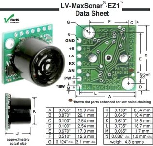
| + | Two ultrasonic transducers sensor type was our first choice, but since it needs to have time measurement between the transmitted trigger signal and received echo which was complex software logic, it got ruled out. Maxbotix sensors have easy-to-use output formats and low power consumption of 2 mA for 3v power. The easier output format was to fetch distance readings in terms of change in analog voltage form at the scale of ~6.4 mV/inch (with a 3.3v supply). | ||
| + | [[File:Maxbotix.jpg|350px|center|thumb|Maxbotix LV-MaxSonar]] | ||
| + | ===== Sensor variants selection to avoid crosstalk and data precision ===== | ||
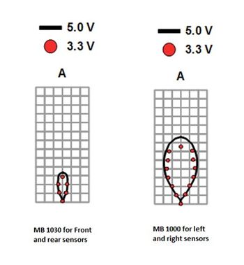
| + | After mounting sensors all together with their alignment, there is the probability of adjacent sensors creating crosstalk in their sensor readings. To avoid this scenario, we have followed a different Maxbotix LV-MaxSonar sensor variant selection approach. One for front and rear sensors, MB1030 series with narrow beam pattern coverage in their transmission vicinity. And another sensor selection for the Left and right sensors, MB1000 has a wider beam pattern to cover maximum obstacles around corner edges. | ||
| + | |||
| + | [[File:sensor_selection.jpg|350px|center|thumb|Beam characteristics of Maxbotix LV-MaxSonar sensors]] | ||
| + | |||
| + | ==== Sensor interface to sjtwo LPC board and signal conditioning ==== | ||
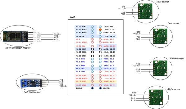
| + | The power given to the Vcc pins of each Maxbotix sensor was +3.3v since it has less current consumption as compared to the +5v interface. Since we were using the Analog output of Maxbotix sensors, onboard ADC (Analog to digital converter) pins were used for the sensor interface. | ||
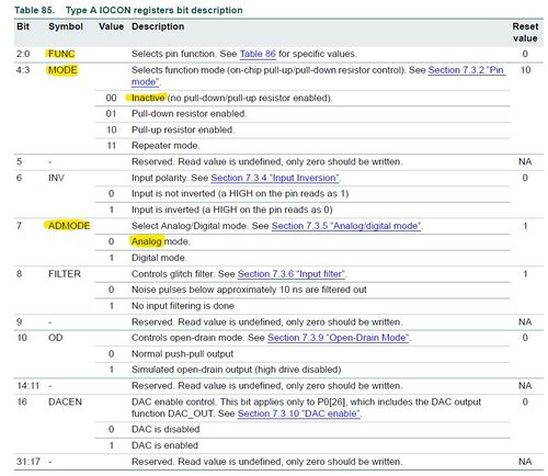
| + | LPC 408x has a 12-bit successive approximation analog to a digital converter. These ADC have been configured to read sensor readings on a scale of 4096 counts. To use sjtwo pins as ADC with better signal accuracy, there was the additional change required in default ADC drivers which require disabling pull-up and pull-down resistors from the IOCON register of each ADC initialization. Maxbotix sensors need to get triggered by logic high pulse on their Rx Pin, this has been implemented by setting a dedicated trigger pin as GPIO output. | ||
| + | |||
| + | |||
| + | [[File:iocon_selection.jpg|500px|center|thumb|ADC initialization configurations]] | ||
| + | |||
| + | By doing IOCON configurations specific to the ADC channel, selection of analog mode, and disabling pull-up, and pull-down mode, sensor inputs were configured for 3 ADC channels and 1 DAC Channel which was configured as ADC by doing appropriate IOCON Selection. | ||
=== Software Design === | === Software Design === | ||
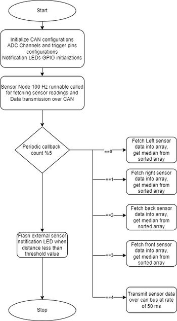
| − | + | Initialization of ADC channels and trigger pins was done before starting sensor data reading inside periodic_callbacks__initialize. | |
| + | Sensor data reading needs to have a faster refresh rate with minimal cross-talk. To achieve this, 100 Hz periodic was used. | ||
| + | To reduce crosstalk between adjacent sensors and power consumption of sensors, sensors were being enabled on a rotation basis following a specific Triggering pattern in the order of Left -> Right -> Rear ->middle. With this order, a 10ms window was given to each sensor. Software should sample 32 sensor readings in a buffer that might contain any abrupt intermittent value which needs to be avoided. By sorting these sensor readings using a quick sorting algorithm, the median was considered as the final end reading for broadcasting over the CAN bus. | ||
| + | |||
| + | [[File:Sensor node flowchart.jpg|350px|center|thumb|Sensor Node Flow chart]] | ||
| + | |||
| + | ==== Periodic execution of Sensor and Bridge Node ==== | ||
| + | sjtwo build environment provides periodic tasks at various execution rates (1Hz, 10Hz, 100Hz). Sensor and Bridge controller developed software effectively utilizes these periodic tasks to sync up with all the nodes which are reading Sensor Bridge node data over CAN Bus. | ||
| + | Periodic Callbacks Initialize: | ||
| + | *Initialize CAN bus: initiailize_can1_bus at 100 kbps baud rate | ||
| + | *Initialize ADC configuration and Trigger Pins: initialize_adc_for_ultra_sonic_sensors(); | ||
| + | *Initialize ADC trigger pins: initialize_pins_for_ultra_sonic_sensor_triggers(); | ||
| + | *Initialize notification LED GPIO configurations. Sensor_car_start_LEDs_initialize(); | ||
| + | *Initialize Line buffer: line_buffer__init(&line, line_buffer, sizeof(line_buffer)); | ||
| + | *Initialize UART configurations for HC-05 Bluetooth: void Bridge_Controller_init(void) | ||
| + | |||
| + | Periodic Callbacks at 1 Hz: | ||
| + | |||
| + | *Run missed-in-action (MIA) handler to check CAN bus status and Flash LEDs if any of the boards are out of network. can_Bridge_Controller__manage_mia_msgs_10hz (); | ||
| + | *Transmit Latched GPS coordinates received from App over Bluetooth. can_bridge_controller__Sending_dest_location(); | ||
| + | |||
| + | Periodic callbacks at 10 Hz: | ||
| + | *Bridge Controller: Read data from UART buffer sent by App | ||
| + | *Line buffer: Remove received data from buffer whenever received specific string format | ||
| + | *Parse GPS coordinates and send over CAN Bus | ||
| + | *Parse Start/ stop command from App, parse it, and broadcast if required | ||
| + | *Bridge runnable: Fetch the latest sensor readings from the Sensor logic handler | ||
| + | |||
| + | Periodic callbacks at 100 Hz: | ||
| + | *Bridge controller: Receive CAN message from all nodes CAN_Rx_all_can_messages_100hz | ||
| + | *Sensor Controller: Fetch all sensor data within 50 ms time frame and transmit over CAN Bus. | ||
| + | Within this function, 32 sample values were sorted first and then the median value is considered as the final one for broadcasting to the driver. | ||
=== Technical Challenges === | === Technical Challenges === | ||
| − | + | *While working on the sensor controller, the biggest challenge was managing data refresh rate which gives precise driver maneuver on obstacle appearance. Tuning the sensor node’s CAN broadcast at 50ms interval was the appropriate solution to delays in steering maneuvers. | |
| + | *Sensor readings and threshold observed instances were tough to analyze whenever the vehicle was in run mode, adding LEDs to every sensor to indicate obstacle presence and processed range value was helpful in the field testing. | ||
| + | *Crosstalk between adjacent sensors was intermittent when all the sensors are transmitting ultrasonic waves simultaneously, this problem has been resolved by defining specific order of sensor trigger which was Left -> Right -> Back - > Front -> CAN Transmit provided each operation with a 10ms window. This solution even helped to reduce the power consumption of sensors whenever their data is not being fetched by the sensor controller. | ||
| + | |||
<HR> | <HR> | ||
<BR/> | <BR/> | ||
| − | == Sensor ECU : Communication Bridge | + | == Sensor and Bridge ECU : Communication Bridge== |
| − | [https://gitlab.com/naveena.sura/silver-arrow/-/tree/BridgeController/ GitLab Link:Sensor and Bridge controller] | + | [https://gitlab.com/naveena.sura/silver-arrow/-/tree/BridgeController/ GitLab Link: Sensor and Bridge controller] |
| + | |||
| + | The bridge controller serves the purpose of communicating with the Android App to receive GPS coordinates to start vehicle motion as well as to receive essential debug information of the running vehicle for field testing. | ||
| + | |||
| + | === Components selection: === | ||
| + | While working on this project statement of bridge controller, the crucial part was to decide the protocol for communication whether it's going to be an on-board ESP8266 module or a Serial communication-based Bluetooth module. Wi-fi was ruled out after assessing the time constraints of this project and because of connectivity availability in test areas. Since data transmission didn’t have any requirement for remote data upload on the server, Bluetooth was the best fit solution providing range connectivity up to 10 meters. | ||
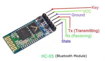
| + | HC-5 Bluetooth module was the first choice because of prior hands-on experience from CMPE 244 and because of its ease of use and configuration options. It uses serial communication to communicate with devices. It communicates with the microcontroller using a serial port (USART). It works on IEEE 802.15.1 standardized protocol, through which one can build a wireless Personal Area Network (PAN). It uses frequency-hopping spread spectrum (FHSS) radio technology to send data over the air. It needs to get powered with 3.3v power to operate in data transfer mode. | ||
=== Hardware Design === | === Hardware Design === | ||
| + | HC-05 Bluetooth module has various features: | ||
| + | * Onboard voltage regulator | ||
| + | * No need for pull-up resistor during powering | ||
| + | *Programmable baud rate, Working mode | ||
| + | |||
| + | [[File:Hc05 wiring.jpg|350px|center|thumb|HC-05 Connection diagram]] | ||
| + | |||
| + | === AT Mode configuration === | ||
| + | To configure Bluetooth module settings such as role (Master/Slave) and Baud rate, it needs to get entered into AT mode. By keeping AT button pressed during powerup, it gets into AT mode by indicating slow blinking of notification of LED, otherwise Fast blinking if waiting for pairing connection. | ||
| + | |||
| + | |||
| + | ====USB to TTL Module Serial Converter==== | ||
| + | This module has easy-to-use UART testing provisions which were useful in Bluetooth module configurations, Bluetooth communication testing as well as GPS data analysis. By connecting Tx and Rx pins of UART in a crisscross fashion, data is being read easily at a defined baud rate on any serial terminal on windows. This module saves time and UART test setup efforts on Arduino/ Raspberry Pi. This is a plug-n-play solution to serial data monitoring. | ||
| + | |||
| + | [[File:Ttl to usb.jpg|350px|center|thumb|TTL To USB module Pinout]] | ||
| + | |||
| + | This is the command set that has been followed before mounting the HC-05 Bluetooth module on the car. | ||
| + | |||
| + | AT | ||
| + | OK | ||
| + | |||
| + | AT+UART? | ||
| + | UART = 38400 //Default | ||
| + | |||
| + | AT +UART = 9600 // new setting | ||
| + | UART = 9600 | ||
| + | |||
| + | AT+ROLE? | ||
| + | 0 - //slave mode | ||
| + | AT+ROLE =0 | ||
| + | |||
| + | AT +CMODE = 0 | ||
| + | //FIXED ADDRESS | ||
=== Software Design === | === Software Design === | ||
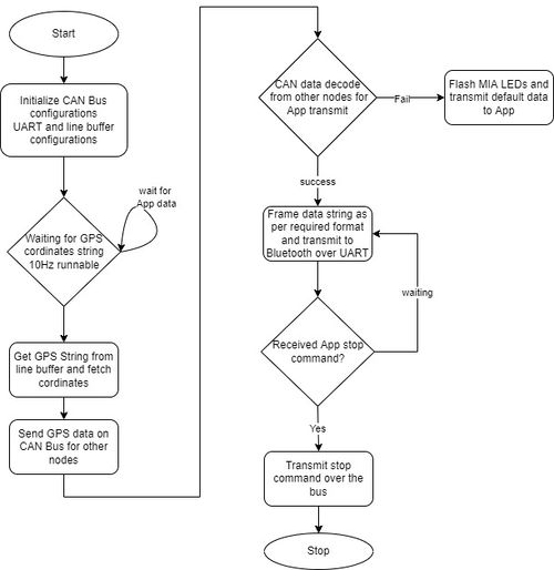
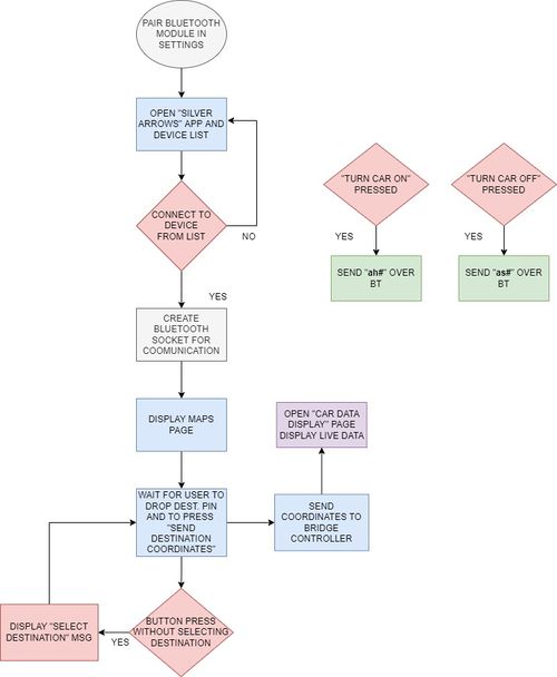
| − | < | + | The bridge controller does receive GPS coordinates only once and once it latches coordinates, it starts sending coordinates over Bluetooth for App UI. |
| + | File:Bridge controller flowchart.jpg | ||
| + | |||
| + | [[File:Bridge controller flowchart.jpg|500px|center|thumb|Bridge controller FlowChart]] | ||
| + | |||
| + | *Bridge_Controller_init: | ||
| + | UART Configurations were initialized to a baud rate of 9600. | ||
| + | The line buffer approach has been used to decode data from App after the end of the buffer by receiving the end of line token ‘#’. In initial App testing, we faced an issue in receiving the ‘\n’ token, to overcome this, we decided to have a different new line token ‘#’. | ||
| + | |||
| + | *Bridge_Controller__10hz_handler: | ||
| + | Sample data string received through App by bridge controller: | ||
| + | |||
| + | GPS37.3373310981467,-121.88254617154598# | ||
| + | |||
| + | Once this string is loaded into static line_buffer after detection of ‘#’ and parsed for sending these coordinates over CAN bus. sscanf c-command was used to fetch specific data and map to static variables through a pointer. Once the string is latched with valid coordinates, the controller will send them over a bus till it receives a new command. | ||
| + | |||
| + | ==== Parsing GPS cordinates from App data string: Code Snippet ==== | ||
| + | <syntaxhighlight lang="cpp"> | ||
| + | sscanf(line_buffer, "GPS%f,%f#", &gps_destination_location.DEST_LATITUDE, &gps_destination_location.DEST_LONGITUDE); | ||
| + | |||
| + | if (gps_destination_location.DEST_LATITUDE != 0 && gps_destination_location.DEST_LONGITUDE != 0 && | ||
| + | !gps_dest_data_latched) { | ||
| + | printf("%s \n", line_buffer); | ||
| + | printf("Latitude is %f and longitude is %f \n", gps_destination_location.DEST_LATITUDE, | ||
| + | gps_destination_location.DEST_LONGITUDE); | ||
| + | |||
| + | gps_destination_location_last_sent.DEST_LONGITUDE = gps_destination_location.DEST_LONGITUDE; | ||
| + | gps_destination_location_last_sent.DEST_LATITUDE = gps_destination_location.DEST_LATITUDE; | ||
| + | gps_dest_data_latched = true; | ||
| + | } | ||
| + | </syntaxhighlight> | ||
| + | |||
| + | ==== Parsing Start/ Stop command from App data string: Code Snippet ==== | ||
| + | Once App has provided a GPS data string, it stays idle till either Start or stop command is given. | ||
| + | The same approach of line buffer and sscanf API was used for the bridge controller. | ||
| + | Start command: “as#” Stop command: “ah#” | ||
| + | Significance of each character | ||
| + | ‘a’: App command | ||
| + | ‘s’: start command | ||
| + | ‘h’: halt or stop command | ||
| + | ‘#’: end of line character | ||
| + | |||
| + | <syntaxhighlight lang="cpp"> | ||
| + | sscanf(line_buffer, "a%c", &app_command); | ||
| + | |||
| + | if ((app_command == 's') && !app_start_command_latched) { | ||
| + | app_stop_command_latched = false; | ||
| + | app_start_command_latched = true; | ||
| + | } else | ||
| + | if ((app_command == 'h') && !app_stop_command_latched) { | ||
| + | app_start_command_latched = false; | ||
| + | app_stop_command_latched = true; | ||
| + | } | ||
| + | |||
| + | if (app_start_command_latched) { | ||
| + | bridge_app_commands.APP_COMMAND = BRIDGE_APP_START_DATA; | ||
| + | printf("start command \n"); | ||
| + | dbc_encode_and_send_BRIDGE_APP_COMMANDS(NULL, &bridge_app_commands); | ||
| + | } else | ||
| + | if (app_stop_command_latched) { | ||
| + | printf("stop command \n"); | ||
| + | gps_dest_data_latched = false; // wait for new gps cordinates | ||
| + | bridge_app_commands.APP_COMMAND = BRIDGE_APP_STOP_DATA; | ||
| + | dbc_encode_and_send_BRIDGE_APP_COMMANDS(NULL, &bridge_app_commands); | ||
| + | } else { | ||
| + | // printf("DEF APP \n"); | ||
| + | bridge_app_commands.APP_COMMAND = BRIDGE_APP_DEFAULT_DATA; | ||
| + | dbc_encode_and_send_BRIDGE_APP_COMMANDS(NULL, &BRIDGE_APP_DEFAULT_DATA); | ||
| + | } | ||
| + | </syntaxhighlight> | ||
| + | |||
| + | ====Bridge controller broadcast data over Bluetooth for Android App ==== | ||
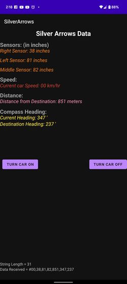
| + | Once the GPS destination is latched by the bridge controller, it starts fetching data decoded by the bridge handler over CAN, and it starts framing strings as per predefined format. | ||
| + | |||
| + | #<2-digit speed>, <2-digit right sensor data>, <2 -digit left sensor data>, <2-digit middle sensor data>, | ||
| + | <3-digit distance towards destination>, <3-digit current compass heading>, <3-digit destination heading>’~’ | ||
| + | ‘#’: start of the string | ||
| + | Each data separated by comma all in series | ||
| + | ‘~’: end of the string as an acknowledgment for App | ||
| + | • Bridge controller 100 Hz periodic: | ||
| + | To maintain the latest data update into static variables,100 Hz periodic was used to decode all parameters from the CAN bus. And they were being transmitted to Android App at a rate of 10 Hz. | ||
| + | |||
| + | <syntaxhighlight lang="cpp"> | ||
| + | void CAN_Rx_all_can_messages_100hz(void) { | ||
| + | can__msg_t can_msg = {0}; | ||
| + | while (can__rx(can1, &can_msg, 0)) { | ||
| + | const dbc_message_header_t header = { | ||
| + | .message_id = can_msg.msg_id, | ||
| + | .message_dlc = can_msg.frame_fields.data_len, | ||
| + | }; | ||
| + | |||
| + | if (dbc_decode_RC_CAR_SPEED_READ_MSG(&motor_speed_read, header, can_msg.data.bytes)) { | ||
| + | |||
| + | typecasted_speed_signal = (uint16_t)motor_speed_read.RC_CAR_SPEED_sig; | ||
| + | } | ||
| + | |||
| + | |||
| + | |||
| + | if (dbc_decode_COMPASS_HEADING_DISTANCE(&geo_heading_distance, header, can_msg.data.bytes)) { | ||
| + | |||
| + | typecasted_distance_data = (uint16_t)geo_heading_distance.DISTANCE; | ||
| + | typecasted_current_heading_data = (uint16_t)geo_heading_distance.CURRENT_HEADING; | ||
| + | typecasted_destination_heading_data = (uint16_t)geo_heading_distance.DESTINATION_HEADING; | ||
| + | } | ||
| + | } | ||
| + | } | ||
| + | </syntaxhighlight> | ||
| + | Bluetooth broadcast data over UART for Bluetooth function Snippet: | ||
| + | |||
| + | <syntaxhighlight lang="cpp"> | ||
| + | bool can_Bridge_Controller_broadcast_data_to_App(void) { | ||
| + | |||
| + | can__msg_t can_msg = {0}; | ||
| + | |||
| + | bool can_rx_message_received = false; | ||
| + | |||
| + | uart__put(bridge_uart, '#', 0); // start of string | ||
| + | // Receive all messages | ||
| + | if (typecasted_speed_signal < 10) { | ||
| + | uart__put(bridge_uart, '0', 0); | ||
| + | Bridge_Controller__Bluetooth_Send_uint16(typecasted_speed_signal, 1); | ||
| + | } else | ||
| + | Bridge_Controller__Bluetooth_Send_uint16(typecasted_speed_signal, 2); | ||
| + | |||
| + | uart__put(bridge_uart, ',', 0); | ||
| + | if (sensor_current_readings.SENSOR_SONARS_right < 10) { | ||
| + | uart__put(bridge_uart, '0', 0); | ||
| + | Bridge_Controller__Bluetooth_Send_uint16(sensor_current_readings.SENSOR_SONARS_right, 1); | ||
| + | } else | ||
| + | Bridge_Controller__Bluetooth_Send_uint16(sensor_current_readings.SENSOR_SONARS_right, 2); | ||
| + | |||
| + | uart__put(bridge_uart, ',', 0); // spacer between 2 parameters | ||
| + | |||
| + | |||
| + | if (typecasted_destination_heading_data < 100 && typecasted_destination_heading_data > 10) { | ||
| + | uart__put(bridge_uart, '0', 0); | ||
| + | Bridge_Controller__Bluetooth_Send_uint16(typecasted_destination_heading_data, 2); | ||
| + | } else if (typecasted_destination_heading_data < 10) { | ||
| + | uart__put(bridge_uart, '0', 0); | ||
| + | uart__put(bridge_uart, '0', 0); | ||
| + | Bridge_Controller__Bluetooth_Send_uint16(typecasted_destination_heading_data, 1); | ||
| + | } else | ||
| + | Bridge_Controller__Bluetooth_Send_uint16(typecasted_destination_heading_data, 3); | ||
| + | |||
| + | uart__put(bridge_uart, '~', 0); // end of tranmsit data buffer token for App decode. | ||
| + | uart__put(bridge_uart, '\n', 0);// New line character for local testing | ||
| + | </syntaxhighlight> | ||
=== Technical Challenges === | === Technical Challenges === | ||
| − | + | *Working with the Line buffer logic and newline character was a challenge during testing. During manual testing of string from TTL to USB converter, Newline character as ‘\n’ was working fine on existing line buffer as well as Unit testing. But when it started receiving data from App, ‘\n’ was difficult to comprehend. We decided to use any different special character as a newline instead of ‘\n’ which we have replaced with ‘#’. Since our existing line buffer’s new line token was easier to replace, ‘#’ proved a perfect solution for integrated testing. | |
| + | *While sending the vehicle to debug information on UART, there was App data misalignment for the sections where their data digit size is varying from 1-digit character to 2-digit character. We have resolved this issue by checking data length before transmission and appending zeros to the specific string whenever required. For e.g. to send compass heading as ‘9’, the string reformed to ‘009’ to maintain string size constant for Android App’s UI stability. | ||
| + | * Rate of Receiving data over CAN bus and rate of bridge sending data to Bluetooth over UART needs to have tight synchronization to avoid intermittent empty data sets, This has been resolved by performing CAN receiving at rate of 100 Hz and Bluetooth data transmit at 10 Hz periodic runnable. | ||
| + | |||
<HR> | <HR> | ||
| Line 420: | Line 806: | ||
== Motor ECU == | == Motor ECU == | ||
| + | [https://gitlab.com/naveena.sura/silver-arrow/-/tree/MOTORCONTROLLER/projects GitLab Link:Motor controller] | ||
=== Hardware Design === | === Hardware Design === | ||
| + | [[File:photo_white.png|800px|caption|center|thumb| Schematic Design]] | ||
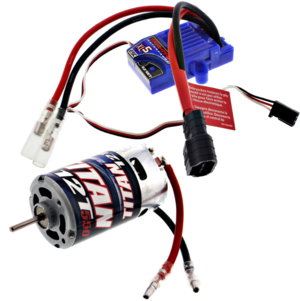
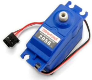
Motor Controller Node includes the operational control of the DC motor, Servo motor, Electronic speed control (ESC), and the wheel encoder(RPM Sensor). The job of the motor controller is to control the steering of front wheels at appropriate angles and to spin the rear wheels at speeds commanded by the driver node in order to traverse the RC car to the destination location.The DC motor, servo motor, and ESC(Traxxas ESC XL-05) were provided with the Traxxas RC car. The wheel encoder and the trigger magnet were purchased separately from Traxxas's website. | Motor Controller Node includes the operational control of the DC motor, Servo motor, Electronic speed control (ESC), and the wheel encoder(RPM Sensor). The job of the motor controller is to control the steering of front wheels at appropriate angles and to spin the rear wheels at speeds commanded by the driver node in order to traverse the RC car to the destination location.The DC motor, servo motor, and ESC(Traxxas ESC XL-05) were provided with the Traxxas RC car. The wheel encoder and the trigger magnet were purchased separately from Traxxas's website. | ||
| Line 447: | Line 835: | ||
==== DC Motor and ESC ==== | ==== DC Motor and ESC ==== | ||
| − | + | The DC motor is controlled by the ESC using PWM signals which were provided by the motor controller board for forward, neutral, and reverse movements.The DC motor and ESC were provided with RC car.The ESC is powered ON using a 7.4 LiPo battery.The ESC converts this 7.4V to 6V and provides input to DC Motor.The car can be operated at 100Hz in the following 3 modes : | |
| − | The DC motor is controlled by the ESC using PWM signals which were provided by the motor controller board for forward, neutral, and reverse movements.The DC motor and ESC were provided with RC car.The ESC is powered ON using a 7.4 LiPo battery.The ESC converts this 7.4V to 6V and provides input to DC Motor. | ||
| − | |||
| − | |||
| − | |||
| − | |||
| − | |||
| − | |||
| − | |||
| − | |||
| − | |||
| − | |||
| − | |||
| − | |||
| − | |||
| − | |||
| − | |||
| − | |||
| − | |||
| − | |||
| − | |||
| − | |||
| − | |||
| − | |||
| − | |||
| − | The car can be operated at 100Hz in the following 3 modes : | ||
<br/> | <br/> | ||
Sport Mode (100% Forward, 100% Brakes, 100% Reverse) | Sport Mode (100% Forward, 100% Brakes, 100% Reverse) | ||
| Line 479: | Line 842: | ||
<br/> | <br/> | ||
Training Mode (50% Forward, 100% Brakes, 50% Reverse) | Training Mode (50% Forward, 100% Brakes, 50% Reverse) | ||
| − | <br><br> | + | <br><br> |
| + | The PWM frequency for our Traxxas esc motor was operated at 100Hz. The duty cycle range for forwarding was 15.01 % to 25% , reverse 10 % to 14.99% and neutral was at 15% duty cycle. | ||
| + | [[File:Dc_motor_esc.png|300px|center|thumb|DC Motor and ESC]] | ||
| + | |||
| + | ==== Servo Motor ==== | ||
| + | The servo motor responds to PWM pulses. It has three pins namely Vcc, PWM Input Signal, and GND. The servo is powered using 6V from the car battery. Based on the PWM signal supplied from the SJTwo board the front wheels are turned.The PWM frequency for our Traxxas Servo motor was operated at 100Hz. The duty cycle range [10%, 15%) is the steer left range, and (15%, 20%] is the steer right. | ||
| + | [[File:Servo_motor.png |300px|center|thumb|Servo Motor]] | ||
| − | <br> | + | ==== Wheel Encoder ==== |
| + | |||
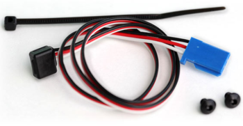
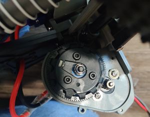
| + | For speed sensing, we purchased a Traxxas RPM sensor as it mounted nicely in the gearbox. The RPM sensor works by mounting a magnet to the spur gear and a hall effect sensor fixed to the gearbox. To get the revolutions per second we used Timer2 as an input capture. <br> | ||
| + | |||
| + | [[File:RPM_Sensor.png|350px|left|thumb|RPM Sensor]][[File:trigger_magnet_Silver.jpg|300px|center|thumb|Trigger Magnet]] | ||
| + | |||
| + | === Software Design === | ||
| + | ==== Motor Software Modules ==== | ||
| + | The software for the motor node was divided into multiple files and made modular to improve readability and understanding of the complex logic involved. The main code modules are for: | ||
| + | |||
| + | <b>DC Motor and Servo Motor</b>: Simple PWM duty cycle was enough to drive both motors. However, finding the dead bands of the duty cycle was a challenging task . We used a logic analyzer and Traxxas transmitter in order to note the operating bands for both. The idle duty cycle for both motors was 15 % . The degree of change in duty cycle varied as per linear interpretation on drive speed from driver to PWM acceptable value. | ||
| + | |||
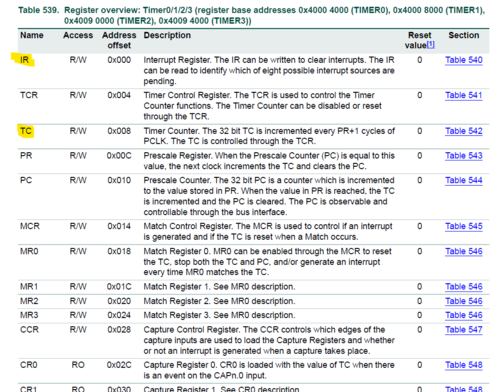
| + | <b>Speed Calculation-RPM Sensor</b>: We combined one of the LPC's peripheral clocks with an input capture function to count the time interval between pulses the RPM sensor emits. When the input is captured, we configured the hardware registers so that the value of the timer count register is written to a capture register. This necessitated the creation of a low-level API in order to unit test the hardware reading and writing. On a capture event, an interrupt is also triggered to reset the timer clock, making it easier to convert the number in the capture register to revolutions per second. To convert rotations per second to standard units of kph, you'll need the circumference of the car's tire and the spur gear ratio. | ||
| − | ==== | + | <pre> |
| − | + | void rpm_sensor__calculate_speed(void) { | |
| + | uint32_t timer_capture_value = LPC_TIM2->CR0; | ||
| + | uint32_t timer_counter_value = LPC_TIM2->TC; | ||
| + | float offset = 37000;//to match inaccuracy | ||
| + | speed_kph = (kph_raw - offset) / timer_capture_value;// where kph_raw = (circumference_of_wheel * 3600) / (wheel_to_gear_ratio * 100000); | ||
| + | |||
| + | } | ||
| + | </pre> | ||
| + | [[File:Timer2.png|thumb|500px|middle|center|TIMER2 Datasheet]] | ||
| − | + | <b>Motor State logic</b>: The state machine logic involved the transition between NEUTRAL, FORWARD, and REVERSE. The state switch from neutral or reverse was easier that involved direct change. However, the transition from forward to reverse had to go through a shift from neutral to reverse two times, and then the third time it shall run in the reverse direction. | |
| − | + | <pre> | |
| − | + | case DRIVE_FORWARD: | |
| − | ! | + | if (current_drive_direction != DRIVE_FORWARD) { |
| − | + | if (current_drive_direction == DRIVE_NEUTRAL) { | |
| − | + | dc_motor__change_drive_speed(target_speed); | |
| − | + | current_drive_direction = DRIVE_FORWARD; | |
| − | + | } else { | |
| − | + | dc_motor__change_drive_speed(0); | |
| − | + | current_drive_direction = DRIVE_NEUTRAL; | |
| − | + | } | |
| − | + | } else { | |
| − | |||
| − | |||
| − | |||
| − | |||
| − | |||
| − | |||
| − | |||
| − | |||
| − | + | double update_pid_speed = target_speed + motor_pid__calculation(target_speed, rpm_sensor__calculate_speed()); | |
| − | < | + | dc_motor__change_drive_speed(update_pid_speed); |
| + | } | ||
| + | break; | ||
| + | case DRIVE_REVERSE: | ||
| + | if (current_drive_direction != DRIVE_REVERSE) { | ||
| + | if (current_drive_direction == DRIVE_NEUTRAL) { | ||
| + | dc_motor__change_drive_speed(target_speed); | ||
| + | current_drive_direction = DRIVE_REVERSE; | ||
| + | } else if (current_drive_direction == DRIVE_REVERSE0) { | ||
| + | dc_motor__change_drive_speed(0); | ||
| + | current_drive_direction = DRIVE_NEUTRAL; | ||
| + | } else if (current_drive_direction == DRIVE_NEUTRAL0) { | ||
| + | dc_motor__change_drive_speed(target_speed); | ||
| + | current_drive_direction = DRIVE_REVERSE0; | ||
| + | } else { | ||
| + | dc_motor__change_drive_speed(0); | ||
| + | current_drive_direction = DRIVE_NEUTRAL0; | ||
| + | } | ||
| + | } | ||
| + | break; | ||
| + | default: | ||
| + | dc_motor__change_drive_speed(0); | ||
| + | current_drive_direction = DRIVE_NEUTRAL; | ||
| + | break; | ||
| + | } | ||
| + | </pre> | ||
| − | |||
| − | + | <b>PID Implementation</b>: To ascend uphill or downhill, a DC motor requires a speed boost, which necessitates the use of a PID controller. In this case, our RPM sensor is quite crucial. The proportional, integral, derivative (PID) controller is a common control method for ensuring that a machine maintains a fixed point and responds to disturbances promptly and smoothly. As demonstrated in equation e(t), we constructed an error buffer to keep the difference between the goal speed and the actual speed determined by the RPM sensor. Based on the total calculation, input is sent to the motor logic, which increases speed while going uphill and decreases speed when going downward. | |
| − | [[File: | + | <pre> |
| + | double motor_pid__calculation(double target_speed, double actual_speed_by_rpm) { | ||
| + | update_error_buffer(target_speed - actual_speed_by_rpm); | ||
| + | return Kp * error_buffer[0] + Ki * error_integral_part() + Kd * error_differetial_part(); | ||
| + | } | ||
| + | </pre> | ||
| + | [[File:Pid_eqn.png|thumb|400px|middle|center|PID Equation]] | ||
| − | + | ==== Periodic Callback Functions ==== | |
| − | + | <b>Periodic Callback: Init</b><br> | |
| − | + | - The CAN bus is initialized <br> | |
| − | + | - The wheel encoder interrupts initialized.<br> | |
| − | + | - The Motor and servo PWM signals are initialized and set to default values. <br> | |
| − | + | <b>Periodic Callback: 1Hz</b><br> | |
| − | + | - Check if the motor board's CAN node is on the bus else reset.<br> | |
| − | + | - Run the self-test.<br> | |
| − | + | - Send the actual car speed from the rpm sensor on the CAN Bus.<br> | |
| − | + | <b>Periodic Callback: 10Hz</b><br> | |
| − | + | - Read all CAN message and filter out the drive speed and steering sent by the Driver node. <br> | |
| − | + | - Control the steering and car movements based on CAN communication with the Master controller.<br> | |
| − | |||
| − | |||
| − | |||
| − | |||
| − | |||
| − | |||
| − | |||
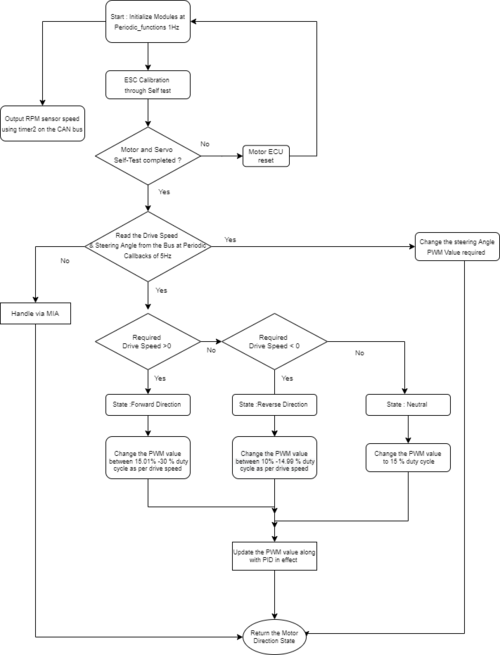
| − | === | + | ==== Implementation Flowchart ==== |
| − | + | [[File:Flowchart silver.drawio.png|thumb|500px|middle|center|Flowchart]] | |
| − | |||
| − | |||
| − | |||
| − | |||
| − | |||
=== Technical Challenges === | === Technical Challenges === | ||
*First and foremost, the Traxxas motor ESC and other Traxxas components are Traxxas Hobby Parts, and they are not designed for development. As a result, no technical specification documentation or program/development guidelines are accessible. The motor ESC must be tested by supplying PWM duty cycles in different sequences at different duty cycle percentages. We utilized the remote control to recreate certain circumstances in which the ESC acted strangely. | *First and foremost, the Traxxas motor ESC and other Traxxas components are Traxxas Hobby Parts, and they are not designed for development. As a result, no technical specification documentation or program/development guidelines are accessible. The motor ESC must be tested by supplying PWM duty cycles in different sequences at different duty cycle percentages. We utilized the remote control to recreate certain circumstances in which the ESC acted strangely. | ||
| + | *Finding the dead bands of the dc motor duty cycle was a challenging task. We used a logic analyzer and Traxxas transmitter in order to note the operating bands for both.This helped us save a lot of time. | ||
*If a Lipo battery is used, the ESC setup switches to the Lipo battery state. When the NiMH battery is replaced, the ESC begins flashing the led in a green-red pattern, and the ESC power button stops working. In this case, the handbook contains a calibration procedure that can rescue your boat and restore regular ESC operation. | *If a Lipo battery is used, the ESC setup switches to the Lipo battery state. When the NiMH battery is replaced, the ESC begins flashing the led in a green-red pattern, and the ESC power button stops working. In this case, the handbook contains a calibration procedure that can rescue your boat and restore regular ESC operation. | ||
*Another challenge with the motor node program development is that you cannot rely on unit testing. Whoever works on the motor node, should make sure that the sequence of the duty cycles being fed to the ESC produces the expected results on the motor as well. The forward-reverse transitioning and the speed controlling both can be a bit tricky. Also, the hard brake logic can take a while to get working properly. | *Another challenge with the motor node program development is that you cannot rely on unit testing. Whoever works on the motor node, should make sure that the sequence of the duty cycles being fed to the ESC produces the expected results on the motor as well. The forward-reverse transitioning and the speed controlling both can be a bit tricky. Also, the hard brake logic can take a while to get working properly. | ||
| Line 561: | Line 961: | ||
The geographical controller handles all compass and GPS data processing. The controller communicates with the Adafruit Ultimate GPS Breakout via UART, which provides accurate GPS data formatted in GPGGA. An antenna has been used to receive the GPS coordinates correctly. The controller uses the I2C protocol to communicate with the Adafruit Magnetometer in order to determine our heading and where the car should point in order to get closer to its destination. The magnetometer provided us with data with a maximum deviation of 5 degrees in any direction. The magnetometer started providing the accurate values only after calibration. | The geographical controller handles all compass and GPS data processing. The controller communicates with the Adafruit Ultimate GPS Breakout via UART, which provides accurate GPS data formatted in GPGGA. An antenna has been used to receive the GPS coordinates correctly. The controller uses the I2C protocol to communicate with the Adafruit Magnetometer in order to determine our heading and where the car should point in order to get closer to its destination. The magnetometer provided us with data with a maximum deviation of 5 degrees in any direction. The magnetometer started providing the accurate values only after calibration. | ||
| − | [[File:GEO_CONTROLLER.png|600px|middle|center]] | + | [[File:GEO_CONTROLLER.png|600px|middle|center|caption|thumb| Geo Controller Connections]] |
| + | |||
{| class="wikitable" width="auto" style="text-align: center; margin-left: auto; margin-right: auto; border: none;" | {| class="wikitable" width="auto" style="text-align: center; margin-left: auto; margin-right: auto; border: none;" | ||
| Line 605: | Line 1,006: | ||
=== Software Design === | === Software Design === | ||
| − | |||
| − | + | The GEO controller consists of three main modules namely GPS processing, compass Processing, and Waypoints Algorithm. These three main module are then used by the GEO logic to determine where the car should be moving. | |
| + | |||
| + | ==== Geo Logic ==== | ||
The GPS module that we used to fetch the current location coordinates transmits data to the GEO controller using UART3. This data is sent to the line buffer to buffer the data and the Geo logic module fetches this data from the line buffer and processes the GPGGA strings to calculate the current polar latitude and longitude coordinates. | The GPS module that we used to fetch the current location coordinates transmits data to the GEO controller using UART3. This data is sent to the line buffer to buffer the data and the Geo logic module fetches this data from the line buffer and processes the GPGGA strings to calculate the current polar latitude and longitude coordinates. | ||
| + | The Geo Controller receives the desired Destination location coordinates from the Bridge Controller on the CAN bus and calculates the destination bearing and the distance to the destination using the haversine formula, which are sent to the DRIVER node over the CAN bus. The current compass heading is also sent to the DRIVER controller which helps it make a decision to steer the car. | ||
| + | |||
| + | This controller is also responsible for directing the car on the shortest path to the destination location using waypoints algorithm(following the checkpoints). Here, when a desired location is entered, and a set of waypoints are given, the Controller selects the next best waypoint using the shortest path algorithm and calculates the destination bearing accordingly. This next best waypoint selection continues until it reaches the desired destination location. These waypoints act as checkpoints to reach the destination in a predestined path instead of a straight path. | ||
The GPS module also provides a FIX signal to indicate whether the GPS module has fixed on a satellite or not. This information from the FIX signal is used to glow an LED to indicate that the GPS signal is fixed. The same information is also sent over CAN bus and displayed on the LCD display for debugging. | The GPS module also provides a FIX signal to indicate whether the GPS module has fixed on a satellite or not. This information from the FIX signal is used to glow an LED to indicate that the GPS signal is fixed. The same information is also sent over CAN bus and displayed on the LCD display for debugging. | ||
| + | |||
| + | [[File:Geo_logic_SilverArrow.png|center|600px|caption|thumb| Flow chart Geo Logic]] | ||
| + | |||
| + | <h3>Parsing Geo Coordinates </h3> | ||
| + | <pre> | ||
| + | static void gps__parse_coordinates_from_line(void){ | ||
| + | char gps_line[120]; | ||
| + | char *ptr_to_gps_data; | ||
| + | const char token = ','; | ||
| + | int found = 0; | ||
| + | if (line_buffer__remove_line(&line, gps_line, sizeof(gps_line))) { | ||
| + | ptr_to_gps_data = strtok(gps_line, ","); | ||
| + | while (ptr_to_gps_data && ((strcmp(ptr_to_gps_data, "$GPGGA") != 0) && | ||
| + | (ptr_to_gps_data < (&gps_line[0] + (sizeof(gps_line) - 5))))) { | ||
| + | ptr_to_gps_data = strtok(NULL, ","); | ||
| + | if (ptr_to_gps_data == NULL) | ||
| + | break; | ||
| + | } | ||
| + | if (ptr_to_gps_data && strcmp(ptr_to_gps_data, "$GPGGA") == 0) { | ||
| + | gps_valid_status = false; | ||
| + | found = 1; | ||
| + | } | ||
| + | if (found == 0) | ||
| + | return; | ||
| + | for (int i = 0; i < 9; i++) { | ||
| + | ptr_to_gps_data = strtok(NULL, ","); | ||
| + | if (i == 1 && ptr_to_gps_data != NULL) { | ||
| + | sscanf(ptr_to_gps_data, "%f", &parsed_coordinates.latitude); | ||
| + | gps_convert_string_to_latitude(); | ||
| + | } else if (i == 2 && ptr_to_gps_data != NULL) { | ||
| + | if (strcmp("S", ptr_to_gps_data) == 0) { | ||
| + | parsed_coordinates.latitude *= -1; | ||
| + | } | ||
| + | } else if (i == 3 && ptr_to_gps_data != NULL) { | ||
| + | sscanf(ptr_to_gps_data, "%f", &parsed_coordinates.longitude); | ||
| + | gps_convert_string_to_longitude(); | ||
| + | gps_valid_status = true; | ||
| + | } else if (i == 4 && ptr_to_gps_data != NULL) { | ||
| + | if (strcmp("W", ptr_to_gps_data) == 0) { | ||
| + | parsed_coordinates.longitude *= -1; | ||
| + | } | ||
| + | } else { | ||
| + | // do nothing | ||
| + | } | ||
| + | } | ||
| + | } else { | ||
| + | // do nothing; | ||
| + | } | ||
| + | } | ||
| + | </pre> | ||
| + | |||
| + | ==== Compass ==== | ||
| + | In our design we have used magnetometer to get the current heading angle of the car. Because of the necessary calibrations that came with the code, the compass module was one of the toughest aspects of the GEO controller. The compass is configured to communicate with the SJ2 board over I2C. The accelerometer was not employed in the early phases of research, but it was necessary to account for tilt while the automobile was driving at high speeds. To get the actual and stable data compass required precise calibration and different mathematical computations. | ||
| + | |||
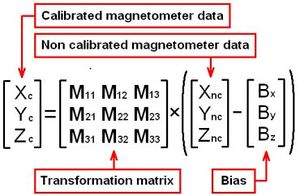
| + | Our method involved first getting raw x, y and z values of the magnetometer from the compass. These values are non calibrated. Hence we then needed modify these value through the added calibration matrixes in the code. How to calculate these values can be find the "Technical Challenges Faced" column. The modified values are then used to calculate the compass heading using the formula as mentioned in the code snippet below | ||
| + | |||
| + | [[File:Compass_(1).jpg|600px|left|caption|thumb| Flow chart Compass Computation]] [[File:compasscalculations.JPG|300px|centre|caption|thumb| Calibration Matrix]] | ||
| + | |||
| + | <h6> Compass calculations </h6> | ||
| + | <pre> | ||
| + | static void get_current_compass_heading(void) { | ||
| + | |||
| + | float magnitude = | ||
| + | sqrtf(magnetometer_processed.x * magnetometer_processed.x + magnetometer_processed.y * magnetometer_processed.y + | ||
| + | magnetometer_processed.z * magnetometer_processed.z); | ||
| + | float Mxz = magnetometer_processed.z / magnitude; | ||
| + | float Mxy = magnetometer_processed.y / magnitude; | ||
| + | float Mxx = magnetometer_processed.x / magnitude; | ||
| + | current_compass_heading = (atan2(Mxy, Mxx)) * 180 / PI; | ||
| + | if (current_compass_heading < 0) { | ||
| + | current_compass_heading = 360 + current_compass_heading; | ||
| + | } | ||
| + | |||
| + | |||
| + | static void transformation_mag(float uncalibrated_values[3]) { | ||
| + | |||
| + | float calibrated_mag_values[3]; | ||
| + | float matrix[3][3] = {{1.207, 0.01, 0.171}, {0.053, 1.152, 0.031}, {-0.014, -0.003, 1.264}}; | ||
| + | float bias[3] = {-62.569, 88.671, 85.599}; | ||
| + | for (int i = 0; i < 3; ++i) | ||
| + | uncalibrated_values[i] = uncalibrated_values[i] - bias[i]; | ||
| + | float result[3] = {0, 0, 0}; | ||
| + | for (int i = 0; i < 3; ++i) | ||
| + | for (int j = 0; j < 3; ++j) | ||
| + | result[i] += matrix[i][j] * uncalibrated_values[j]; | ||
| + | for (int i = 0; i < 3; ++i) | ||
| + | calibrated_mag_values[i] = result[i]; | ||
| + | |||
| + | magnetometer_processed.x = calibrated_mag_values[0]; | ||
| + | magnetometer_processed.y = calibrated_mag_values[1]; | ||
| + | magnetometer_processed.z = calibrated_mag_values[2]; | ||
| + | } | ||
| + | |||
| + | static void get_raw_compass_data(void) { | ||
| + | uint8_t magnetometer_data[6] = {0U}; | ||
| + | uint8_t items_to_read = 6; | ||
| + | float mag[3]; | ||
| + | i2c__read_slave_data(current_i2c, magnetometer_read, compass_magnetomer_OUT_X_H_M, magnetometer_data, items_to_read); | ||
| + | |||
| + | mag[0] = (int16_t)(magnetometer_data[1] | (int16_t)(magnetometer_data[0] << 8)); | ||
| + | mag[2] = (int16_t)(magnetometer_data[3] | (int16_t)(magnetometer_data[2] << 8)); | ||
| + | mag[1] = (int16_t)(magnetometer_data[5] | (int16_t)(magnetometer_data[4] << 8)); | ||
| + | // printf("mag 0 %f, mag 1 %f, mag 2 %f\n", mag[0], mag[1], mag[2]); | ||
| + | transformation_mag(mag); | ||
| + | } | ||
| + | </pre> | ||
| + | |||
==== Waypoint Algorithm ==== | ==== Waypoint Algorithm ==== | ||
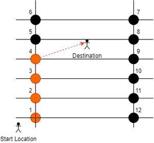
| + | In real world, the car just cannot move anywhere over the roads and need to maintain a particular path and find the best possible and smallest route to its final destination. Hence, we have used waypoint algorithm in our implementation. These waypoints are known coordinates on a given location and our algorithm rather than just going in any one direction, follow the path through these waypoints. These waypoints are kind of checkpoints between the origin and the final destination and our car will follow these points to reach to the final location. | ||
| + | How does it work? | ||
| + | Here we have chosen 12 points over a known location as shown in the image below. These waypoints form a grid of points (all black and orange dots). Once our car gets the final coordinates, our waypoint algorithm runs on the GEO NODE and gives the DRIVER NODE directions for best waypoint. This waypoint must satisfy the below conditions: | ||
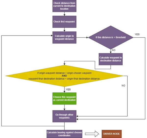
| + | * It is the closest waypoint to the current location of the car. | ||
| + | * Waypoint to destination distance is less than the current coordinate to the final coordinate distance. | ||
| + | |||
| + | So when the algorithm finds the destination coordinates, then bearing is calculated with that particular coordinate, so that car can be further instructions to move towards that particular point. As shown in the figure below, our algorithm keeps finding new coordinates with time (orange ones) and at last go to the final destination coordinates. The algorithm is mentioned below in the form of flowchart and code: | ||
| + | |||
| + | [[File:Waypoint.jpg|300px|left|caption|thumb| Pictorial representation of Wave point Algorithm]] [[File:Waypointflowchart_(1).jpg|600px|centre|caption|thumb| Flowchart of Algorithm]] | ||
| + | |||
| + | <h6> Waypoint algorithm code</h6> | ||
| + | <pre> | ||
| + | gps_coordinates_t find_next_point(gps_coordinates_t origin, gps_coordinates_t destination) { | ||
| + | const float origin_to_destination_distance = calculate_distance_rc_car_to_destination_in_meters(origin, destination); | ||
| + | float waypoint_distance_to_destination = 0; | ||
| + | float origin_distance_to_waypoint = 0; | ||
| + | float closest_way_point_ditsance = 1E+37; | ||
| + | uint8_t waypoint_array_location = 0; | ||
| − | [[ | + | for (uint8_t i = 0; i < max_points; i++) { |
| + | origin_distance_to_waypoint = | ||
| + | calculate_distance_rc_car_to_destination_in_meters(origin, locations_we_can_travel[i]); | ||
| + | waypoint_distance_to_destination = | ||
| + | calculate_distance_rc_car_to_destination_in_meters(locations_we_can_travel[i], destination); | ||
| + | if (origin_distance_to_waypoint < 0.005) | ||
| + | continue; | ||
| + | if ((origin_distance_to_waypoint <= closest_way_point_distance) && | ||
| + | (waypoint_distance_to_destination < origin_to_destination_distance)) { | ||
| + | waypoint_array_location = i; | ||
| + | closest_way_point_distance = origin_distance_to_waypoint; | ||
| + | } else { | ||
| + | // do nothing | ||
| + | } | ||
| + | } | ||
| + | if (origin_to_destination_distance <= closest_way_point_disance) { | ||
| + | set_bearing_for_waypoint(origin, destination); | ||
| + | return destination; | ||
| + | } else { | ||
| + | set_bearing_for_waypoint(origin, locations_we_can_travel[waypoint_array_location]); | ||
| + | return locations_we_can_travel[waypoint_array_location]; | ||
| + | } | ||
| + | } | ||
| + | </pre> | ||
=== Technical Challenges === | === Technical Challenges === | ||
| + | * '''Calibration''': We faced a lot of problems while calibrating the compass. We first used the two point approach, however it did not give the results as wanted and we always ended up getting different values at different run We then used the matrix calibration method t get the stable values. The magmaster approach was the most elaborate and not overly complex when using YuriMat's Arduino software. We then used transformation matrix and bias value to point compass same as the actual compass. | ||
| + | Below is the link for the method which we followed: | ||
| + | https://www.instructables.com/Easy-hard-and-soft-iron-magnetometer-calibration/ | ||
| − | + | * '''GPS Module''': We faced some issues with GPS not giving accurate values of the current coordinates. We analyzed and researched that GPS needs good power supply to give accurate results. So we attached a non-divided circuit for GPS so that it standalone gets the power. | |
| + | * '''Waypoint Algorithm''': While running the waypoint algorithm there was a corner case in which the car was just moving between 2 way points and unable to reach the final destination. It was because, our waypoints were at the same distance from the final destination. In order to save this, we applied a safety check to skip the last chosen waypoint so that no loop exist. | ||
| + | * '''GPS fix''' is best when when there are no obstruction above the module. Module requires clear wide view of sky for a fast fix and error free location detection. | ||
<HR> | <HR> | ||
<BR/> | <BR/> | ||
== Master Module == | == Master Module == | ||
| + | [https://gitlab.com/naveena.sura/silver-arrow/-/commits/DRIVER_NODE/ GitLab Link: Driver Controller] | ||
| + | |||
The master module or the DRIVER NODE is the central node of our system which controls the navigation of the car. It takes he sensor values from the SENSOR NODE and geographical data from the GEO NODE and takes the navigation decision as per algorithm and sends the motor commands to the MOTOR NODE. | The master module or the DRIVER NODE is the central node of our system which controls the navigation of the car. It takes he sensor values from the SENSOR NODE and geographical data from the GEO NODE and takes the navigation decision as per algorithm and sends the motor commands to the MOTOR NODE. | ||
| Line 629: | Line 1,189: | ||
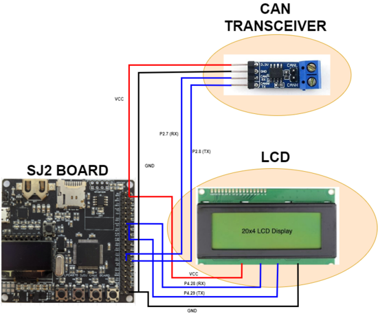
The driver node is the main node responsible for moving the car to the destination as it receives appropriate messages from the bridge-sensor node and geo node and processes the signals before sending speed and steering values to the motor node. The LCD has also been interfaced to the DRIVER node and communicates with the controller via UART. The LCD displays messages, which helped us in debugging messages on the CAN bus while the car was moving. | The driver node is the main node responsible for moving the car to the destination as it receives appropriate messages from the bridge-sensor node and geo node and processes the signals before sending speed and steering values to the motor node. The LCD has also been interfaced to the DRIVER node and communicates with the controller via UART. The LCD displays messages, which helped us in debugging messages on the CAN bus while the car was moving. | ||
| − | [[File:DRIVER_LCD_1.png|550px|middle|center]] | + | [[File:DRIVER_LCD_1.png|550px|middle|center|caption|thumb|Connetions of Driver Controller]] |
{| class="wikitable" width="auto" style="text-align: center; margin-left: auto; margin-right: auto; border: none;" | {| class="wikitable" width="auto" style="text-align: center; margin-left: auto; margin-right: auto; border: none;" | ||
| Line 669: | Line 1,229: | ||
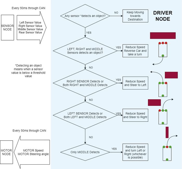
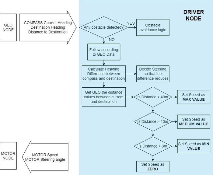
This logic navigate the car according to the objects detected by the ultrasonic sensors mounted over the SENSOR NODE. As the object is detected, driver takes appropriate decisions and navigate the car without hitting the detected object. The algorithm is briefly described in the flow chart below. | This logic navigate the car according to the objects detected by the ultrasonic sensors mounted over the SENSOR NODE. As the object is detected, driver takes appropriate decisions and navigate the car without hitting the detected object. The algorithm is briefly described in the flow chart below. | ||
| − | [[File:ObjectDetection.jpg|700px|middle|centre]] | + | [[File:ObjectDetection.jpg|700px|middle|centre|thumb| Object Detection Logic]] |
<h6>Navigation according to object detection algorithm: </h6> | <h6>Navigation according to object detection algorithm: </h6> | ||
| Line 849: | Line 1,409: | ||
=== Technical Challenges === | === Technical Challenges === | ||
| + | * There were very minimal hardware challenges faced on this node as it has least external sensors or devices connected. | ||
| + | * There were a lot of algorithm changes done to bring smoothness into the navigation of the car, such as the steering angles and how much periodicity must be used for all rx and tx from driver node | ||
== Mobile Application == | == Mobile Application == | ||
| Line 922: | Line 1,484: | ||
<HR> | <HR> | ||
<BR/> | <BR/> | ||
| + | |||
| + | == Unit Testing == | ||
| + | |||
| + | Unit testing has been performed for all the nodes. We used “CMock” to test the code coverage and proper execution and flow of our program. Each line of code we design is testable, and the most efficient way to test it is through unit-tests. A unit test is a method of testing a unit, which is the smallest amount of code in a system that can be logically separated. That is a function, a subroutine, a method, or a property in most programming languages. CMock is a framework for generating mocks based on a header API. All you have to do to use CMock is add a mock header file to the test suite file. The figure below illustrates the main functions tested for all the four nodes. | ||
| + | |||
| + | [[File:unit testing report.png|1100px|middle|center]] | ||
== Conclusion == | == Conclusion == | ||
| − | + | The RC car project was a great success! We were able to meet all of the conditions that were placed on us. The car could travel itself from one waypoint to the next while keeping a constant speed and avoiding obstructions. This project encompasses a wide range of disciplines, including mechanical engineering, embedded engineering, android development, and project management, all of which we had no prior expertise with. We gained a better grasp of embedded systems and strong software design principles, such as test-driven development, while also acquiring new information while working on this project. Interfacing with ultrasonic sensors and performing signal processing on the data, interacting with a GPS module, determining heading from a magnetometer and incorporating tilt compensation using an accelerometer, writing firmware for a Bluetooth module and communicating with an Android application that we created, interacting with electric motors using PWM and creating a PID to control speed, and not to mention our deep dive into the CAN protocol and not only learning the intricacies of the CAN protocol and not only learning the intricacies Many of these jobs necessitated extensive research to gain a thorough understanding of subjects before we could begin. With each iteration, we learned that it is important for a project team to set certain achievable milestones. Conquering these milestones will help one to get a better idea of where one stands with respect to the final deadline date. | |
| − | + | A few takeaways from this project include: | |
| − | + | * How to write good software that is testable. | |
| + | * Unit-testing saves a lot of time. | ||
| + | * To avoid constant overwriting, use Git to manage various versions of code and merge features to target branches, rather than uploading individual files. | ||
| + | * Project Management and working together in a group. Coming to a consensus when the views and opinions of group members don't match. | ||
| + | * How easy it is to build a basic mobile application | ||
=== Project Video === | === Project Video === | ||
| + | ''' [https://youtu.be/mY946w4Qfxg/ Silver Arrow Youtube link]''' | ||
=== Project Source Code === | === Project Source Code === | ||
| + | ''' [https://gitlab.com/naveena.sura/silver-arrow/ Silver Arrow GitLab ]''' | ||
| − | === | + | === Advice for Future Students === |
| − | + | * Start Early. Go through previous years' wiki pages and set achievable milestones. Starting early provides your team with a number of advantages over other teams. You'll run into problems sooner, which means you'll have more time to fix them. Also, if your team gets started early, you may always check to see if the modules they purchased are malfunctioning. | |
| + | * Invest in good parts and always buy spare parts. "Good Parts" may not necessarily be "expensive". We went through different project teams and used their advice on what parts to order and not. Don't underestimate the amount of mechanical design and work that goes into getting things up and running. | ||
| + | * Figure out the power circuit as soon as possible. Even though it is possible to power the different modules and their subsequent peripherals from the car's ESC, it is advised NOT to do that. Be extra careful while making connections as this project has a lot. Use color coding for wire and avoid "spaghetti wire". You'll need enough current to power all of the controllers and components. | ||
| + | * Integrating LCD on the car chassis helps a lot as it is better to decode the car (even when it's moving) than connecting the DB9 connector and looking over the BUSMASTER. | ||
=== Acknowledgement === | === Acknowledgement === | ||
| + | We want to express our gratitude to Professor Preetpal Kang for sharing valuable inputs and knowledge throughout the duration of the project. We really appreciate Professor Dr. Haluk Ozemek's help with valuable technical guidance and financial assistance while working on this RC car project. We would also like to thank the project groups of previous years, which helped us to avoid the mistakes made by them which that we saved an invaluable amount of time | ||
=== References === | === References === | ||
| + | [https://developer.android.com/guide/topics/connectivity/bluetooth/transfer-data#kotlin/ Android Bluetooth Data Transfer] | ||
| + | |||
| + | [https://www.pololu.com/file/0J434/LSM303DLH-compass-app-note.pdf/ LSM303DLH-compass-app-note] | ||
| + | |||
| + | [https://www.instructables.com/Easy-hard-and-soft-iron-magnetometer-calibration/ Compass Calibration] | ||
Latest revision as of 18:46, 28 May 2022
Contents
- 1 SILVER ARROW
- 2 Abstract
- 3 Schedule
- 4 Parts List & Cost
- 5 Project Design
- 6 CAN Communication
- 7 Sensor and Bridge ECU : Sensors
- 8 Sensor and Bridge ECU : Communication Bridge
- 9 Motor ECU
- 10 Geographical Controller
- 11 Master Module
- 12 Mobile Application
- 13 Unit Testing
- 14 Conclusion
SILVER ARROW
Abstract
Silver Arrow RC is a self-navigating, electric, battery-powered RC car. The goal is to use GPS navigation to get to the location specified in the Android app. To sense its surroundings and avoid obstructions in its route, the car combines input from several sensors and make decisions to navigate itself to the destination location
Introduction
The project was divided into 5 modules:
- Bridge and Sensor Controller
- Motor Controller
- Geographical Controller
- Driver and LCD controller
- Android Application
Team Members & Responsibilities
- Driver Node
- Compass & GPS Calibration
- Waypoint algorithm
- Mobile Application
- Car Mounting and hardware assembly
- Wiki page manage
- Sensor controller
- Communication Bridge Controller
- Hardware and App Integration
- Geo controller
- LCD Integration
- Geo controller
- Line Buffer, Geo Logic and Waypoint algorithm
- Git repo manager
- Motor controller
- Hardware Integration and design
- Code Reviewer
- Unit Testing
- Hardware/circuit/PCB designing
Schedule
| Week# | Start Date | End Date | Task | Status |
|---|---|---|---|---|
| 1 | 03/16/2022 | 03/22/2022 |
|
|
| 2 |
03/23/2022
|
03/29/2022
|
|
|
| 3 |
03/30/2022
|
03/04/2022
|
|
|
| 4 |
04/05/2022
|
04/11/2022
|
|
|
| 5 |
04/12/2022
|
04/18/2022
|
|
|
| 6 |
04/19/2022
|
04/25/2022
|
|
|
| 7 |
04/26/2022
|
05/2/2022
|
|
|
| 8 |
05/3/2022
|
05/09/2022
|
|
|
| 9 |
05/10/2022
|
05/16/2022
|
|
|
| 10 |
05/17/2022
|
05/23/2022
|
|
|
| 11 |
05/25/2022
|
05/25/2022
|
|
|
Parts List & Cost
| Item# | Part Desciption | Vendor | Qty | Cost |
|---|---|---|---|---|
| 1 | The Traxxas Rustler XL-5® Stadium Truck | Traxxas [1] | 1 | $250.00 |
| 2 | Waveshare SN65HVD230 CAN Transceivers | Amazon [2] | 6 | $59.34 |
| 3 | Adafruit Ultimate GPS Breakout | Adafruit [3] | 1 | $29.95 |
| 4 | LCD 20*4 | RPIGEAR [4] | 1 | $30 |
| 5 | Adafruit GPS Antenna | Adafruit [5] | 1 | $19.95 |
| 6 | DC 5v voltage regulator XL6009 | Amazon [6] | 1 | $11.99 |
| 7 | Traxxas 6520 RPM Sensor | Traxxas [7] | 1 | $13.76 |
| 8 | Traxxas Trigger Magnet | Traxxas [8] | 1 | $3 |
| 9 | Maxbotix LV-MaxSonar-EZ1 Ultrasonic Range Finder | Amazon [9] | 4 | $120 ( Provided by Dr. Ozemek) |
| 10 | Traxxas LiPo Batteries(2) with Dual iD charger(1) | Traxxas [10] | 1 | $269.99 ( Provided by Dr. Ozemek) |
| 11 | DSD TECH HC-05 Bluetooth Serial Pass-through Module | Amazon[11] | 1 | $9.99 |
| 12 | HiLetgo CP2102 USB 2.0 to TTL Module Serial Converter | Amazon [12] | 1 | $6.29 |
| 13 | Connecting wires, LEDs, switches | Anchor electronics [13] | 1 | $97 |
Project Design
CAN Communication
CAN protocol was used to establish the communication between the four controllers. The Message IDs for the messages transmitted by the four controllers were selected such that the data that has to be sampled more often than others had the highest priority in arbitration. We also used Debug CAN messages to output any necessary information needed for Debugging, like the GPS fix lock, Destination bearing etc.,
Different controllers are configured to transmit their messages at different periodicities based on the data sampling rate needed for smooth movement of the car.
Hardware Design
We used the CAN in Full CAN mode at 100Kbps baud rate, and enabled hardware filtering to receive only the messages needed. Four CAN transceivers were used to connect the Controllers to the CAN bus. Terminal resistors of 120 Ohms are used at the ends of the CAN bus to reduce signal reflection.
DBC File
VERSION ""

NS_ :
	BA_
	BA_DEF_
	BA_DEF_DEF_
	BA_DEF_DEF_REL_
	BA_DEF_REL_
	BA_DEF_SGTYPE_
	BA_REL_
	BA_SGTYPE_
	BO_TX_BU_
	BU_BO_REL_
	BU_EV_REL_
	BU_SG_REL_
	CAT_
	CAT_DEF_
	CM_
	ENVVAR_DATA_
	EV_DATA_
	FILTER
	NS_DESC_
	SGTYPE_
	SGTYPE_VAL_
	SG_MUL_VAL_
	SIGTYPE_VALTYPE_
	SIG_GROUP_
	SIG_TYPE_REF_
	SIG_VALTYPE_
	VAL_
	VAL_TABLE_

BS_:

BU_: DBG DRIVER IO MOTOR SENSOR GEO


BO_ 100 BRIDGE_APP_COMMANDS: 1 SENSOR
 SG_ APP_COMMAND : 0|2@1+ (1,0) [0|0] "" GEO,DRIVER

BO_ 101 MOTOR_CHANGE_SPEED_AND_ANGLE_MSG: 2 DRIVER
 SG_ DC_MOTOR_DRIVE_SPEED_sig : 0|8@1+ (0.1,-10) [-10|10] "kph" MOTOR
 SG_ SERVO_STEER_ANGLE_sig : 8|8@1+ (1,-45) [-45|45] "degrees" MOTOR

BO_ 102 SENSOR_SONARS_ROUTINE: 5 SENSOR
 SG_ SENSOR_SONARS_left : 0|10@1+ (1,0) [0|0] "inch" DRIVER
 SG_ SENSOR_SONARS_right : 10|10@1+ (1,0) [0|0] "inch" DRIVER
 SG_ SENSOR_SONARS_middle : 20|10@1+ (1,0) [0|0] "inch" DRIVER
 SG_ SENSOR_SONARS_rear : 30|10@1+ (1,0) [0|0] "inch" DRIVER

BO_ 300 GPS_DESTINATION_LOCATION: 8 SENSOR
 SG_ DEST_LATITUDE : 0|32@1+ (0.000001,-90.000000) [-90|90] "Degrees" GEO
 SG_ DEST_LONGITUDE : 32|32@1+ (0.000001,-180.000000) [-180|180] "Degrees" GEO

BO_ 301 COMPASS_HEADING_DISTANCE: 6 GEO
 SG_ CURRENT_HEADING : 0|12@1+ (0.1,0) [0|359.9] "Degrees" DRIVER,SENSOR
 SG_ DESTINATION_HEADING: 12|12@1+ (0.1,0) [0|359.9] "Degrees" DRIVER,SENSOR
 SG_ DISTANCE : 24|17@1+ (0.01,0) [0|0] "Meters" DRIVER,SENSOR

BO_ 501 GPS_CURRENT_INFO: 8 GEO
 SG_ GPS_CURRENT_LAT : 0|32@1+ (0.000001,-90.000000) [-90|90] "degrees" DRIVER,SENSOR,MOTOR
 SG_ GPS_CURRENT_LONG : 32|32@1+ (0.000001,-180.000000) [-180|180] "degrees" DRIVER,SENSOR,MOTOR

BO_ 502 GPS_COMPASS_STATUS : 1 GEO
 SG_ COMPASS_LOCK_VALID: 0|1@1+ (1,0) [0|0] "TRUE_FALSE" DRIVER, SENSOR
 SG_ GPS_LOCK_VALID : 1|1@1+ (1,0) [0|0] "TRUE_FALSE" DRIVER,SENSOR,MOTOR

BO_ 503 GPS_CURRENT_DESTINATIONS_DATA: 8 GEO
 SG_ CURRENT_DEST_LATITUDE : 0|32@1+ (0.000001,-90.000000) [-90|90] "Degrees" DRIVER
 SG_ CURRENT_DEST_LONGITUDE : 32|32@1+ (0.000001,-180.000000) [-180|180] "Degrees" DRIVER

BO_ 504 RC_CAR_SPEED_READ_MSG: 2 MOTOR
  SG_ RC_CAR_SPEED_sig : 0|8@1+ (0.1,-10) [-10|10] "kph" DRIVER,SENSOR

BO_ 750 DBG_RAW_COMPASS_DATA: 4 GEO
  SG_ SIGNED_REGISTER_VAL_MAG_X : 0|16@1+ (1.0,0) [-2048|2047] "GAUSSIAN" DRIVER,SENSOR
  SG_ SIGNED_REGISTER_VAL_MAG_Y : 16|16@1+ (1.0,0) [-2048|2047] "GAUSSIAN" DRIVER,SENSOR

BO_ 751 DBG_CONFIRM_RECEIVED_DESTINATION: 8 GEO
 SG_ RECEIVED_DEST_LATITUDE : 0|32@1+ (0.000001,-90.000000) [-90|90] "Degrees" SENSOR
 SG_ RECEIVED_DEST_LONGITUDE : 32|32@1+ (0.000001,-180.000000) [-180|180] "Degrees" SENSOR

BO_ 775 DBG_GPS_COMPASS_LOCK_LED_CHECK: 1 GEO
 SG_ COMPASS_LED_STATUS: 0|1@1+ (1,0) [0|0] "TRUE_FALSE" DRIVER, SENSOR, MOTOR
 SG_ GPS_LED_STATUS : 1|1@1+ (1,0) [0|0] "TRUE_FALSE" DRIVER, SENSOR, MOTOR

BO_ 780 DBG_GEO_CAN_STATUS: 3 GEO
 SG_ DBG_CAN_INIT_STATUS: 0|1@1+ (1,0) [0|0] "TRUE_FALSE" DRIVER, SENSOR, MOTOR
 SG_ DBG_CAN_RX_DROP_COUNT : 1|16@1+ (1,0) [0|0] "TRUE_FALSE" DRIVER,SENSOR,MOTOR

BO_ 781 DBG_SENSOR_CAN_STATUS: 3 SENSOR
 SG_ DBG_CAN_INIT_STATUS: 0|1@1+ (1,0) [0|0] "TRUE_FALSE" DRIVER, GEO, MOTOR
 SG_ DBG_CAN_RX_DROP_COUNT : 1|16@1+ (1,0) [0|0] "TRUE_FALSE" DRIVER,GEO,MOTOR

BO_ 782 DBG_MOTOR_CAN_STATUS: 3 MOTOR
 SG_ DBG_CAN_INIT_STATUS: 0|1@1+ (1,0) [0|0] "TRUE_FALSE" DRIVER, SENSOR, GEO
 SG_ DBG_CAN_RX_DROP_COUNT : 1|16@1+ (1,0) [0|0] "TRUE_FALSE" DRIVER,SENSOR,GEO

BO_ 783 DBG_DRIVER_CAN_STATUS: 3 DRIVER
 SG_ DBG_CAN_INIT_STATUS: 0|1@1+ (1,0) [0|0] "TRUE_FALSE" GEO, SENSOR, MOTOR
 SG_ DBG_CAN_RX_DROP_COUNT : 1|16@1+ (1,0) [0|0] "TRUE_FALSE" GEO,SENSOR,MOTOR

BO_ 784 DBG_MOTOR_INFO_MSG: 4 MOTOR
  SG_ DC_MOTOR_CURRENT_PWM _sig: 0|8@1+ (0.1,0) [0|0] "duty percent" DRIVER
  SG_ SERVO_MOTOR_CURRENT_PWM_sig : 8|8@1+ (0.1,0) [0|0] "duty percent" DRIVER
  SG_ PID_OUTPUT_VALUE_sig : 16|8@1+ (0.1,-10) [0|0] "kph" DRIVER
  SG_ MOTOR_SELF_TEST_sig : 24|1@1+ (1,0) [0|0] "TRUE_FALSE" DRIVER

BO_ 001 DRIVER_HEARTBEAT: 1 DRIVER
 SG_ DRIVER_HEARTBEAT_cmd : 0|8@1+ (1,0) [0|0] "" SENSOR,MOTOR

BO_ 002 SENSOR_HEARTBEAT: 1 SENSOR
 SG_ DRIVER_HEARTBEAT_cmd : 0|8@1+ (1,0) [0|0] "" SENSOR,MOTOR

BO_ 003 GEO_HEARTBEAT: 1 GEO
 SG_ DRIVER_HEARTBEAT_cmd : 0|8@1+ (1,0) [0|0] "" SENSOR,MOTOR

BO_ 004 MOTOR_HEARTBEAT_MSG: 1 MOTOR
  SG_ MOTOR_HEARTBEAT_sig : 0|8@1+ (1,0) [0|255] "pulse" DRIVER

CM_ BU_ DRIVER "The driver controller driving the car";
CM_ BU_ MOTOR "The motor controller of the car";
CM_ BU_ SENSOR "The sensor controller of the car";
CM_ BO_ 100 "Sync message used to synchronize the controllers";
CM_ SG_ 100 DRIVER_HEARTBEAT_cmd "Heartbeat command from the driver";

BA_DEF_ "BusType" STRING ;
BA_DEF_ BO_ "GenMsgCycleTime" INT 0 0;
BA_DEF_ SG_ "FieldType" STRING ;

BA_DEF_DEF_ "BusType" "CAN";
BA_DEF_DEF_ "FieldType" "";
BA_DEF_DEF_ "GenMsgCycleTime" 0;

BA_ "GenMsgCycleTime" BO_ 100 1000;
BA_ "GenMsgCycleTime" BO_ 200 50;
BA_ "FieldType" SG_ 100 DRIVER_HEARTBEAT_cmd "DRIVER_HEARTBEAT_cmd";

VAL_ 100 DRIVER_HEARTBEAT_cmd 2 "DRIVER_HEARTBEAT_cmd_REBOOT" 1 "DRIVER_HEARTBEAT_cmd_SYNC" 0 "DRIVER_HEARTBEAT_cmd_NOOP" ;
Sensor and Bridge ECU : Sensors
GitLab Link:Sensor and Bridge controller
Hardware Design
The sensor part of the bridge and sensor ECU board is responsible for receiving the sensor readings, converting them to Inches, and then sending them to the driver controller board over CAN Bus.
Component selection
Sensor selection was a critical part of the sensor controller because time constraints and range data accuracy were the key challenges. Two ultrasonic transducers sensor type was our first choice, but since it needs to have time measurement between the transmitted trigger signal and received echo which was complex software logic, it got ruled out. Maxbotix sensors have easy-to-use output formats and low power consumption of 2 mA for 3v power. The easier output format was to fetch distance readings in terms of change in analog voltage form at the scale of ~6.4 mV/inch (with a 3.3v supply).
Sensor variants selection to avoid crosstalk and data precision
After mounting sensors all together with their alignment, there is the probability of adjacent sensors creating crosstalk in their sensor readings. To avoid this scenario, we have followed a different Maxbotix LV-MaxSonar sensor variant selection approach. One for front and rear sensors, MB1030 series with narrow beam pattern coverage in their transmission vicinity. And another sensor selection for the Left and right sensors, MB1000 has a wider beam pattern to cover maximum obstacles around corner edges.
Sensor interface to sjtwo LPC board and signal conditioning
The power given to the Vcc pins of each Maxbotix sensor was +3.3v since it has less current consumption as compared to the +5v interface. Since we were using the Analog output of Maxbotix sensors, onboard ADC (Analog to digital converter) pins were used for the sensor interface. LPC 408x has a 12-bit successive approximation analog to a digital converter. These ADC have been configured to read sensor readings on a scale of 4096 counts. To use sjtwo pins as ADC with better signal accuracy, there was the additional change required in default ADC drivers which require disabling pull-up and pull-down resistors from the IOCON register of each ADC initialization. Maxbotix sensors need to get triggered by logic high pulse on their Rx Pin, this has been implemented by setting a dedicated trigger pin as GPIO output.
By doing IOCON configurations specific to the ADC channel, selection of analog mode, and disabling pull-up, and pull-down mode, sensor inputs were configured for 3 ADC channels and 1 DAC Channel which was configured as ADC by doing appropriate IOCON Selection.
Software Design
Initialization of ADC channels and trigger pins was done before starting sensor data reading inside periodic_callbacks__initialize. Sensor data reading needs to have a faster refresh rate with minimal cross-talk. To achieve this, 100 Hz periodic was used. To reduce crosstalk between adjacent sensors and power consumption of sensors, sensors were being enabled on a rotation basis following a specific Triggering pattern in the order of Left -> Right -> Rear ->middle. With this order, a 10ms window was given to each sensor. Software should sample 32 sensor readings in a buffer that might contain any abrupt intermittent value which needs to be avoided. By sorting these sensor readings using a quick sorting algorithm, the median was considered as the final end reading for broadcasting over the CAN bus.
Periodic execution of Sensor and Bridge Node
sjtwo build environment provides periodic tasks at various execution rates (1Hz, 10Hz, 100Hz). Sensor and Bridge controller developed software effectively utilizes these periodic tasks to sync up with all the nodes which are reading Sensor Bridge node data over CAN Bus. Periodic Callbacks Initialize:
- Initialize CAN bus: initiailize_can1_bus at 100 kbps baud rate
- Initialize ADC configuration and Trigger Pins: initialize_adc_for_ultra_sonic_sensors();
- Initialize ADC trigger pins: initialize_pins_for_ultra_sonic_sensor_triggers();
- Initialize notification LED GPIO configurations. Sensor_car_start_LEDs_initialize();
- Initialize Line buffer: line_buffer__init(&line, line_buffer, sizeof(line_buffer));
- Initialize UART configurations for HC-05 Bluetooth: void Bridge_Controller_init(void)
Periodic Callbacks at 1 Hz:
- Run missed-in-action (MIA) handler to check CAN bus status and Flash LEDs if any of the boards are out of network. can_Bridge_Controller__manage_mia_msgs_10hz ();
- Transmit Latched GPS coordinates received from App over Bluetooth. can_bridge_controller__Sending_dest_location();
Periodic callbacks at 10 Hz:
- Bridge Controller: Read data from UART buffer sent by App
- Line buffer: Remove received data from buffer whenever received specific string format
- Parse GPS coordinates and send over CAN Bus
- Parse Start/ stop command from App, parse it, and broadcast if required
- Bridge runnable: Fetch the latest sensor readings from the Sensor logic handler
Periodic callbacks at 100 Hz:
- Bridge controller: Receive CAN message from all nodes CAN_Rx_all_can_messages_100hz
- Sensor Controller: Fetch all sensor data within 50 ms time frame and transmit over CAN Bus.
Within this function, 32 sample values were sorted first and then the median value is considered as the final one for broadcasting to the driver.
Technical Challenges
- While working on the sensor controller, the biggest challenge was managing data refresh rate which gives precise driver maneuver on obstacle appearance. Tuning the sensor node’s CAN broadcast at 50ms interval was the appropriate solution to delays in steering maneuvers.
- Sensor readings and threshold observed instances were tough to analyze whenever the vehicle was in run mode, adding LEDs to every sensor to indicate obstacle presence and processed range value was helpful in the field testing.
- Crosstalk between adjacent sensors was intermittent when all the sensors are transmitting ultrasonic waves simultaneously, this problem has been resolved by defining specific order of sensor trigger which was Left -> Right -> Back - > Front -> CAN Transmit provided each operation with a 10ms window. This solution even helped to reduce the power consumption of sensors whenever their data is not being fetched by the sensor controller.
Sensor and Bridge ECU : Communication Bridge
GitLab Link: Sensor and Bridge controller
The bridge controller serves the purpose of communicating with the Android App to receive GPS coordinates to start vehicle motion as well as to receive essential debug information of the running vehicle for field testing.
Components selection:
While working on this project statement of bridge controller, the crucial part was to decide the protocol for communication whether it's going to be an on-board ESP8266 module or a Serial communication-based Bluetooth module. Wi-fi was ruled out after assessing the time constraints of this project and because of connectivity availability in test areas. Since data transmission didn’t have any requirement for remote data upload on the server, Bluetooth was the best fit solution providing range connectivity up to 10 meters. HC-5 Bluetooth module was the first choice because of prior hands-on experience from CMPE 244 and because of its ease of use and configuration options. It uses serial communication to communicate with devices. It communicates with the microcontroller using a serial port (USART). It works on IEEE 802.15.1 standardized protocol, through which one can build a wireless Personal Area Network (PAN). It uses frequency-hopping spread spectrum (FHSS) radio technology to send data over the air. It needs to get powered with 3.3v power to operate in data transfer mode.
Hardware Design
HC-05 Bluetooth module has various features:
- Onboard voltage regulator
- No need for pull-up resistor during powering
- Programmable baud rate, Working mode
AT Mode configuration
To configure Bluetooth module settings such as role (Master/Slave) and Baud rate, it needs to get entered into AT mode. By keeping AT button pressed during powerup, it gets into AT mode by indicating slow blinking of notification of LED, otherwise Fast blinking if waiting for pairing connection.
USB to TTL Module Serial Converter
This module has easy-to-use UART testing provisions which were useful in Bluetooth module configurations, Bluetooth communication testing as well as GPS data analysis. By connecting Tx and Rx pins of UART in a crisscross fashion, data is being read easily at a defined baud rate on any serial terminal on windows. This module saves time and UART test setup efforts on Arduino/ Raspberry Pi. This is a plug-n-play solution to serial data monitoring.
This is the command set that has been followed before mounting the HC-05 Bluetooth module on the car.
AT OK
AT+UART? UART = 38400 //Default
AT +UART = 9600 // new setting UART = 9600
AT+ROLE? 0 - //slave mode AT+ROLE =0
AT +CMODE = 0 //FIXED ADDRESS
Software Design
The bridge controller does receive GPS coordinates only once and once it latches coordinates, it starts sending coordinates over Bluetooth for App UI. File:Bridge controller flowchart.jpg
- Bridge_Controller_init:
UART Configurations were initialized to a baud rate of 9600. The line buffer approach has been used to decode data from App after the end of the buffer by receiving the end of line token ‘#’. In initial App testing, we faced an issue in receiving the ‘\n’ token, to overcome this, we decided to have a different new line token ‘#’.
- Bridge_Controller__10hz_handler:
Sample data string received through App by bridge controller:
GPS37.3373310981467,-121.88254617154598#
Once this string is loaded into static line_buffer after detection of ‘#’ and parsed for sending these coordinates over CAN bus. sscanf c-command was used to fetch specific data and map to static variables through a pointer. Once the string is latched with valid coordinates, the controller will send them over a bus till it receives a new command.
Parsing GPS cordinates from App data string: Code Snippet
  sscanf(line_buffer, "GPS%f,%f#", &gps_destination_location.DEST_LATITUDE, &gps_destination_location.DEST_LONGITUDE);

  if (gps_destination_location.DEST_LATITUDE != 0 && gps_destination_location.DEST_LONGITUDE != 0 &&
      !gps_dest_data_latched) {
    printf("%s \n", line_buffer);
    printf("Latitude is %f and longitude is %f \n", gps_destination_location.DEST_LATITUDE,
           gps_destination_location.DEST_LONGITUDE);

    gps_destination_location_last_sent.DEST_LONGITUDE = gps_destination_location.DEST_LONGITUDE;
    gps_destination_location_last_sent.DEST_LATITUDE = gps_destination_location.DEST_LATITUDE;
    gps_dest_data_latched = true;
    }
Parsing Start/ Stop command from App data string: Code Snippet
Once App has provided a GPS data string, it stays idle till either Start or stop command is given. The same approach of line buffer and sscanf API was used for the bridge controller. Start command: “as#” Stop command: “ah#” Significance of each character ‘a’: App command ‘s’: start command ‘h’: halt or stop command ‘#’: end of line character
sscanf(line_buffer, "a%c", &app_command);

  if ((app_command == 's') && !app_start_command_latched) {
    app_stop_command_latched = false;
    app_start_command_latched = true;
  } else
  if ((app_command == 'h') && !app_stop_command_latched) {
    app_start_command_latched = false;
    app_stop_command_latched = true;
  }

  if (app_start_command_latched) {
    bridge_app_commands.APP_COMMAND = BRIDGE_APP_START_DATA;
    printf("start command \n");
    dbc_encode_and_send_BRIDGE_APP_COMMANDS(NULL, &bridge_app_commands);
  } else
  if (app_stop_command_latched) {
    printf("stop command \n");
    gps_dest_data_latched = false; // wait for new gps cordinates
    bridge_app_commands.APP_COMMAND = BRIDGE_APP_STOP_DATA;
    dbc_encode_and_send_BRIDGE_APP_COMMANDS(NULL, &bridge_app_commands);
  } else {
    // printf("DEF APP \n");
    bridge_app_commands.APP_COMMAND = BRIDGE_APP_DEFAULT_DATA;
    dbc_encode_and_send_BRIDGE_APP_COMMANDS(NULL, &BRIDGE_APP_DEFAULT_DATA);
  }
Bridge controller broadcast data over Bluetooth for Android App
Once the GPS destination is latched by the bridge controller, it starts fetching data decoded by the bridge handler over CAN, and it starts framing strings as per predefined format.
- <2-digit speed>, <2-digit right sensor data>, <2 -digit left sensor data>, <2-digit middle sensor data>,
<3-digit distance towards destination>, <3-digit current compass heading>, <3-digit destination heading>’~’ ‘#’: start of the string Each data separated by comma all in series ‘~’: end of the string as an acknowledgment for App • Bridge controller 100 Hz periodic: To maintain the latest data update into static variables,100 Hz periodic was used to decode all parameters from the CAN bus. And they were being transmitted to Android App at a rate of 10 Hz.
void CAN_Rx_all_can_messages_100hz(void) {
  can__msg_t can_msg = {0};
  while (can__rx(can1, &can_msg, 0)) {
    const dbc_message_header_t header = {
        .message_id = can_msg.msg_id,
        .message_dlc = can_msg.frame_fields.data_len,
    };

    if (dbc_decode_RC_CAR_SPEED_READ_MSG(&motor_speed_read, header, can_msg.data.bytes)) {

      typecasted_speed_signal = (uint16_t)motor_speed_read.RC_CAR_SPEED_sig;
    }


    if (dbc_decode_COMPASS_HEADING_DISTANCE(&geo_heading_distance, header, can_msg.data.bytes)) {

      typecasted_distance_data = (uint16_t)geo_heading_distance.DISTANCE;
      typecasted_current_heading_data = (uint16_t)geo_heading_distance.CURRENT_HEADING;
      typecasted_destination_heading_data = (uint16_t)geo_heading_distance.DESTINATION_HEADING;
    }
  }
}
Bluetooth broadcast data over UART for Bluetooth function Snippet:
bool can_Bridge_Controller_broadcast_data_to_App(void) {

  can__msg_t can_msg = {0};

  bool can_rx_message_received = false;

  uart__put(bridge_uart, '#', 0); // start of string
                                  // Receive all messages
  if (typecasted_speed_signal < 10) {
    uart__put(bridge_uart, '0', 0);
    Bridge_Controller__Bluetooth_Send_uint16(typecasted_speed_signal, 1);
  } else
    Bridge_Controller__Bluetooth_Send_uint16(typecasted_speed_signal, 2);

  uart__put(bridge_uart, ',', 0);
  if (sensor_current_readings.SENSOR_SONARS_right < 10) {
    uart__put(bridge_uart, '0', 0);
    Bridge_Controller__Bluetooth_Send_uint16(sensor_current_readings.SENSOR_SONARS_right, 1);
  } else
    Bridge_Controller__Bluetooth_Send_uint16(sensor_current_readings.SENSOR_SONARS_right, 2);

  uart__put(bridge_uart, ',', 0); // spacer between 2 parameters


  if (typecasted_destination_heading_data < 100 && typecasted_destination_heading_data > 10) {
    uart__put(bridge_uart, '0', 0);
    Bridge_Controller__Bluetooth_Send_uint16(typecasted_destination_heading_data, 2);
  } else if (typecasted_destination_heading_data < 10) {
    uart__put(bridge_uart, '0', 0);
    uart__put(bridge_uart, '0', 0);
    Bridge_Controller__Bluetooth_Send_uint16(typecasted_destination_heading_data, 1);
  } else
    Bridge_Controller__Bluetooth_Send_uint16(typecasted_destination_heading_data, 3);

  uart__put(bridge_uart, '~', 0); // end of tranmsit data buffer token for App decode.
  uart__put(bridge_uart, '\n', 0);// New line character for local testing
Technical Challenges
- Working with the Line buffer logic and newline character was a challenge during testing. During manual testing of string from TTL to USB converter, Newline character as ‘\n’ was working fine on existing line buffer as well as Unit testing. But when it started receiving data from App, ‘\n’ was difficult to comprehend. We decided to use any different special character as a newline instead of ‘\n’ which we have replaced with ‘#’. Since our existing line buffer’s new line token was easier to replace, ‘#’ proved a perfect solution for integrated testing.
- While sending the vehicle to debug information on UART, there was App data misalignment for the sections where their data digit size is varying from 1-digit character to 2-digit character. We have resolved this issue by checking data length before transmission and appending zeros to the specific string whenever required. For e.g. to send compass heading as ‘9’, the string reformed to ‘009’ to maintain string size constant for Android App’s UI stability.
- Rate of Receiving data over CAN bus and rate of bridge sending data to Bluetooth over UART needs to have tight synchronization to avoid intermittent empty data sets, This has been resolved by performing CAN receiving at rate of 100 Hz and Bluetooth data transmit at 10 Hz periodic runnable.
Motor ECU
Hardware Design
Motor Controller Node includes the operational control of the DC motor, Servo motor, Electronic speed control (ESC), and the wheel encoder(RPM Sensor). The job of the motor controller is to control the steering of front wheels at appropriate angles and to spin the rear wheels at speeds commanded by the driver node in order to traverse the RC car to the destination location.The DC motor, servo motor, and ESC(Traxxas ESC XL-05) were provided with the Traxxas RC car. The wheel encoder and the trigger magnet were purchased separately from Traxxas's website.
| SJ2 Board Pin | Description |
|---|---|
| 5V | Input power |
| 3.3V | CAN transceiver power |
| PWM2 P2.1 | DC Motor Speed Control |
| PWM5 P2.4 | Servo Motor Angle Control |
| CAP0 P2.6 | RPM Sensor\Wheel Encoder |
| CAN1 TX | CAN Transceiver Tx |
| CAN1 RX | CAN Transceiver Rx |
| GND | Grounding |
DC Motor and ESC
The DC motor is controlled by the ESC using PWM signals which were provided by the motor controller board for forward, neutral, and reverse movements.The DC motor and ESC were provided with RC car.The ESC is powered ON using a 7.4 LiPo battery.The ESC converts this 7.4V to 6V and provides input to DC Motor.The car can be operated at 100Hz in the following 3 modes :
Sport Mode (100% Forward, 100% Brakes, 100% Reverse)
Racing Mode (100% Forward, 100% Brakes, No Reverse)
Training Mode (50% Forward, 100% Brakes, 50% Reverse)
The PWM frequency for our Traxxas esc motor was operated at 100Hz. The duty cycle range for forwarding was 15.01 % to 25% , reverse 10 % to 14.99% and neutral was at 15% duty cycle.
Servo Motor
The servo motor responds to PWM pulses. It has three pins namely Vcc, PWM Input Signal, and GND. The servo is powered using 6V from the car battery. Based on the PWM signal supplied from the SJTwo board the front wheels are turned.The PWM frequency for our Traxxas Servo motor was operated at 100Hz. The duty cycle range [10%, 15%) is the steer left range, and (15%, 20%] is the steer right.
Wheel Encoder
For speed sensing, we purchased a Traxxas RPM sensor as it mounted nicely in the gearbox. The RPM sensor works by mounting a magnet to the spur gear and a hall effect sensor fixed to the gearbox. To get the revolutions per second we used Timer2 as an input capture.
Software Design
Motor Software Modules
The software for the motor node was divided into multiple files and made modular to improve readability and understanding of the complex logic involved. The main code modules are for:
DC Motor and Servo Motor: Simple PWM duty cycle was enough to drive both motors. However, finding the dead bands of the duty cycle was a challenging task . We used a logic analyzer and Traxxas transmitter in order to note the operating bands for both. The idle duty cycle for both motors was 15 % . The degree of change in duty cycle varied as per linear interpretation on drive speed from driver to PWM acceptable value.
Speed Calculation-RPM Sensor: We combined one of the LPC's peripheral clocks with an input capture function to count the time interval between pulses the RPM sensor emits. When the input is captured, we configured the hardware registers so that the value of the timer count register is written to a capture register. This necessitated the creation of a low-level API in order to unit test the hardware reading and writing. On a capture event, an interrupt is also triggered to reset the timer clock, making it easier to convert the number in the capture register to revolutions per second. To convert rotations per second to standard units of kph, you'll need the circumference of the car's tire and the spur gear ratio.
void rpm_sensor__calculate_speed(void) {
  uint32_t timer_capture_value = LPC_TIM2->CR0;
  uint32_t timer_counter_value = LPC_TIM2->TC;
  float offset = 37000;//to match inaccuracy
  speed_kph = (kph_raw - offset) / timer_capture_value;// where kph_raw = (circumference_of_wheel * 3600) / (wheel_to_gear_ratio * 100000);

}
Motor State logic: The state machine logic involved the transition between NEUTRAL, FORWARD, and REVERSE. The state switch from neutral or reverse was easier that involved direct change. However, the transition from forward to reverse had to go through a shift from neutral to reverse two times, and then the third time it shall run in the reverse direction.
case DRIVE_FORWARD:
    if (current_drive_direction != DRIVE_FORWARD) {
      if (current_drive_direction == DRIVE_NEUTRAL) {
        dc_motor__change_drive_speed(target_speed);
        current_drive_direction = DRIVE_FORWARD;
      } else {
        dc_motor__change_drive_speed(0);
        current_drive_direction = DRIVE_NEUTRAL;
      }
    } else {

      double update_pid_speed = target_speed + motor_pid__calculation(target_speed, rpm_sensor__calculate_speed());
      dc_motor__change_drive_speed(update_pid_speed);
    }
    break;
  case DRIVE_REVERSE:
    if (current_drive_direction != DRIVE_REVERSE) {
      if (current_drive_direction == DRIVE_NEUTRAL) {
        dc_motor__change_drive_speed(target_speed);
        current_drive_direction = DRIVE_REVERSE;
      } else if (current_drive_direction == DRIVE_REVERSE0) {
        dc_motor__change_drive_speed(0);
        current_drive_direction = DRIVE_NEUTRAL;
      } else if (current_drive_direction == DRIVE_NEUTRAL0) {
        dc_motor__change_drive_speed(target_speed);
        current_drive_direction = DRIVE_REVERSE0;
      } else {
        dc_motor__change_drive_speed(0);
        current_drive_direction = DRIVE_NEUTRAL0;
      }
    }
    break;
  default:
    dc_motor__change_drive_speed(0);
    current_drive_direction = DRIVE_NEUTRAL;
    break;
  }
PID Implementation: To ascend uphill or downhill, a DC motor requires a speed boost, which necessitates the use of a PID controller. In this case, our RPM sensor is quite crucial. The proportional, integral, derivative (PID) controller is a common control method for ensuring that a machine maintains a fixed point and responds to disturbances promptly and smoothly. As demonstrated in equation e(t), we constructed an error buffer to keep the difference between the goal speed and the actual speed determined by the RPM sensor. Based on the total calculation, input is sent to the motor logic, which increases speed while going uphill and decreases speed when going downward.
double motor_pid__calculation(double target_speed, double actual_speed_by_rpm) {
  update_error_buffer(target_speed - actual_speed_by_rpm);
  return Kp * error_buffer[0] + Ki * error_integral_part() + Kd * error_differetial_part();
}
Periodic Callback Functions
Periodic Callback: Init
- The CAN bus is initialized
- The wheel encoder interrupts initialized.
- The Motor and servo PWM signals are initialized and set to default values.
Periodic Callback: 1Hz
- Check if the motor board's CAN node is on the bus else reset.
- Run the self-test.
- Send the actual car speed from the rpm sensor on the CAN Bus.
Periodic Callback: 10Hz
- Read all CAN message and filter out the drive speed and steering sent by the Driver node.
- Control the steering and car movements based on CAN communication with the Master controller.
Implementation Flowchart
Technical Challenges
- First and foremost, the Traxxas motor ESC and other Traxxas components are Traxxas Hobby Parts, and they are not designed for development. As a result, no technical specification documentation or program/development guidelines are accessible. The motor ESC must be tested by supplying PWM duty cycles in different sequences at different duty cycle percentages. We utilized the remote control to recreate certain circumstances in which the ESC acted strangely.
- Finding the dead bands of the dc motor duty cycle was a challenging task. We used a logic analyzer and Traxxas transmitter in order to note the operating bands for both.This helped us save a lot of time.
- If a Lipo battery is used, the ESC setup switches to the Lipo battery state. When the NiMH battery is replaced, the ESC begins flashing the led in a green-red pattern, and the ESC power button stops working. In this case, the handbook contains a calibration procedure that can rescue your boat and restore regular ESC operation.
- Another challenge with the motor node program development is that you cannot rely on unit testing. Whoever works on the motor node, should make sure that the sequence of the duty cycles being fed to the ESC produces the expected results on the motor as well. The forward-reverse transitioning and the speed controlling both can be a bit tricky. Also, the hard brake logic can take a while to get working properly.
Geographical Controller
Hardware Design
The geographical controller handles all compass and GPS data processing. The controller communicates with the Adafruit Ultimate GPS Breakout via UART, which provides accurate GPS data formatted in GPGGA. An antenna has been used to receive the GPS coordinates correctly. The controller uses the I2C protocol to communicate with the Adafruit Magnetometer in order to determine our heading and where the car should point in order to get closer to its destination. The magnetometer provided us with data with a maximum deviation of 5 degrees in any direction. The magnetometer started providing the accurate values only after calibration.
| SJTwo Board | GPS/Compass Module | Description |
|---|---|---|
| P4.28 (TX3) | RX | Adafruit GPS Breakout |
| P4.29 (RX3) | TX | Adafruit GPS Breakout |
| P0.10 (SDA) | SDA | Adafruit Magnetometer |
| P0.10 (SCL) | SCL | Adafruit Magnetometer |
| P2.8 | CAN transceiver (Tx) | CAN transmit |
| P2.7 | CAN transceiver (Rx) | CAN receive |
| Vcc 3.3V | Vcc | Vcc |
| GND | GND | Ground |
Software Design
The GEO controller consists of three main modules namely GPS processing, compass Processing, and Waypoints Algorithm. These three main module are then used by the GEO logic to determine where the car should be moving.
Geo Logic
The GPS module that we used to fetch the current location coordinates transmits data to the GEO controller using UART3. This data is sent to the line buffer to buffer the data and the Geo logic module fetches this data from the line buffer and processes the GPGGA strings to calculate the current polar latitude and longitude coordinates. The Geo Controller receives the desired Destination location coordinates from the Bridge Controller on the CAN bus and calculates the destination bearing and the distance to the destination using the haversine formula, which are sent to the DRIVER node over the CAN bus. The current compass heading is also sent to the DRIVER controller which helps it make a decision to steer the car.
This controller is also responsible for directing the car on the shortest path to the destination location using waypoints algorithm(following the checkpoints). Here, when a desired location is entered, and a set of waypoints are given, the Controller selects the next best waypoint using the shortest path algorithm and calculates the destination bearing accordingly. This next best waypoint selection continues until it reaches the desired destination location. These waypoints act as checkpoints to reach the destination in a predestined path instead of a straight path.
The GPS module also provides a FIX signal to indicate whether the GPS module has fixed on a satellite or not. This information from the FIX signal is used to glow an LED to indicate that the GPS signal is fixed. The same information is also sent over CAN bus and displayed on the LCD display for debugging.
Parsing Geo Coordinates
static void gps__parse_coordinates_from_line(void){
  char gps_line[120];
  char *ptr_to_gps_data;
  const char token = ',';
  int found = 0;
  if (line_buffer__remove_line(&line, gps_line, sizeof(gps_line))) {
    ptr_to_gps_data = strtok(gps_line, ",");
    while (ptr_to_gps_data && ((strcmp(ptr_to_gps_data, "$GPGGA") != 0) &&
           (ptr_to_gps_data < (&gps_line[0] + (sizeof(gps_line) - 5))))) {
      ptr_to_gps_data = strtok(NULL, ",");
      if (ptr_to_gps_data == NULL)
        break;
    }
    if (ptr_to_gps_data && strcmp(ptr_to_gps_data, "$GPGGA") == 0) {
      gps_valid_status = false;
      found = 1;
    }
    if (found == 0)
      return;
    for (int i = 0; i < 9; i++) {
      ptr_to_gps_data = strtok(NULL, ",");
      if (i == 1 && ptr_to_gps_data != NULL) {
        sscanf(ptr_to_gps_data, "%f", &parsed_coordinates.latitude);
        gps_convert_string_to_latitude();
      } else if (i == 2 && ptr_to_gps_data != NULL) {
        if (strcmp("S", ptr_to_gps_data) == 0) {
          parsed_coordinates.latitude *= -1;
        }
      } else if (i == 3 && ptr_to_gps_data != NULL) {
        sscanf(ptr_to_gps_data, "%f", &parsed_coordinates.longitude);
        gps_convert_string_to_longitude();
        gps_valid_status = true;
      } else if (i == 4 && ptr_to_gps_data != NULL) {
        if (strcmp("W", ptr_to_gps_data) == 0) {
          parsed_coordinates.longitude *= -1;
        }
      } else {
        // do nothing
      }
    }
  } else {
    // do nothing;
  }
}
Compass
In our design we have used magnetometer to get the current heading angle of the car. Because of the necessary calibrations that came with the code, the compass module was one of the toughest aspects of the GEO controller. The compass is configured to communicate with the SJ2 board over I2C. The accelerometer was not employed in the early phases of research, but it was necessary to account for tilt while the automobile was driving at high speeds. To get the actual and stable data compass required precise calibration and different mathematical computations.
Our method involved first getting raw x, y and z values of the magnetometer from the compass. These values are non calibrated. Hence we then needed modify these value through the added calibration matrixes in the code. How to calculate these values can be find the "Technical Challenges Faced" column. The modified values are then used to calculate the compass heading using the formula as mentioned in the code snippet below
Compass calculations
static void get_current_compass_heading(void) {

  float magnitude =
      sqrtf(magnetometer_processed.x * magnetometer_processed.x + magnetometer_processed.y * magnetometer_processed.y +
            magnetometer_processed.z * magnetometer_processed.z);
  float Mxz = magnetometer_processed.z / magnitude;
  float Mxy = magnetometer_processed.y / magnitude;
  float Mxx = magnetometer_processed.x / magnitude;
  current_compass_heading = (atan2(Mxy, Mxx)) * 180 / PI;
  if (current_compass_heading < 0) {
    current_compass_heading = 360 + current_compass_heading;
  }


static void transformation_mag(float uncalibrated_values[3]) {

  float calibrated_mag_values[3];
  float matrix[3][3] = {{1.207, 0.01, 0.171}, {0.053, 1.152, 0.031}, {-0.014, -0.003, 1.264}};
  float bias[3] = {-62.569, 88.671, 85.599};
  for (int i = 0; i < 3; ++i)
    uncalibrated_values[i] = uncalibrated_values[i] - bias[i];
  float result[3] = {0, 0, 0};
  for (int i = 0; i < 3; ++i)
    for (int j = 0; j < 3; ++j)
      result[i] += matrix[i][j] * uncalibrated_values[j];
  for (int i = 0; i < 3; ++i)
    calibrated_mag_values[i] = result[i];

  magnetometer_processed.x = calibrated_mag_values[0];
  magnetometer_processed.y = calibrated_mag_values[1];
  magnetometer_processed.z = calibrated_mag_values[2];
}

static void get_raw_compass_data(void) {
  uint8_t magnetometer_data[6] = {0U};
  uint8_t items_to_read = 6;
  float mag[3];
  i2c__read_slave_data(current_i2c, magnetometer_read, compass_magnetomer_OUT_X_H_M, magnetometer_data, items_to_read);

  mag[0] = (int16_t)(magnetometer_data[1] | (int16_t)(magnetometer_data[0] << 8));
  mag[2] = (int16_t)(magnetometer_data[3] | (int16_t)(magnetometer_data[2] << 8));
  mag[1] = (int16_t)(magnetometer_data[5] | (int16_t)(magnetometer_data[4] << 8));
  // printf("mag 0 %f, mag 1 %f, mag 2 %f\n", mag[0], mag[1], mag[2]);
  transformation_mag(mag);
}
Waypoint Algorithm
In real world, the car just cannot move anywhere over the roads and need to maintain a particular path and find the best possible and smallest route to its final destination. Hence, we have used waypoint algorithm in our implementation. These waypoints are known coordinates on a given location and our algorithm rather than just going in any one direction, follow the path through these waypoints. These waypoints are kind of checkpoints between the origin and the final destination and our car will follow these points to reach to the final location. How does it work? Here we have chosen 12 points over a known location as shown in the image below. These waypoints form a grid of points (all black and orange dots). Once our car gets the final coordinates, our waypoint algorithm runs on the GEO NODE and gives the DRIVER NODE directions for best waypoint. This waypoint must satisfy the below conditions:
- It is the closest waypoint to the current location of the car.
- Waypoint to destination distance is less than the current coordinate to the final coordinate distance.
So when the algorithm finds the destination coordinates, then bearing is calculated with that particular coordinate, so that car can be further instructions to move towards that particular point. As shown in the figure below, our algorithm keeps finding new coordinates with time (orange ones) and at last go to the final destination coordinates. The algorithm is mentioned below in the form of flowchart and code:
Waypoint algorithm code
gps_coordinates_t find_next_point(gps_coordinates_t origin, gps_coordinates_t destination) {
  const float origin_to_destination_distance = calculate_distance_rc_car_to_destination_in_meters(origin, destination);
  float waypoint_distance_to_destination = 0;
  float origin_distance_to_waypoint = 0;
  float closest_way_point_ditsance = 1E+37;
  uint8_t waypoint_array_location = 0;

  for (uint8_t i = 0; i < max_points; i++) {
    origin_distance_to_waypoint =
        calculate_distance_rc_car_to_destination_in_meters(origin, locations_we_can_travel[i]);
    waypoint_distance_to_destination =
        calculate_distance_rc_car_to_destination_in_meters(locations_we_can_travel[i], destination);
    if (origin_distance_to_waypoint < 0.005)
      continue;
    if ((origin_distance_to_waypoint <= closest_way_point_distance) &&
        (waypoint_distance_to_destination < origin_to_destination_distance)) {
      waypoint_array_location = i;
      closest_way_point_distance = origin_distance_to_waypoint;
    } else {
      // do nothing
    }
  }
  if (origin_to_destination_distance <= closest_way_point_disance) {
    set_bearing_for_waypoint(origin, destination);
    return destination;
  } else {
    set_bearing_for_waypoint(origin, locations_we_can_travel[waypoint_array_location]);
    return locations_we_can_travel[waypoint_array_location];
  }
}
Technical Challenges
- Calibration: We faced a lot of problems while calibrating the compass. We first used the two point approach, however it did not give the results as wanted and we always ended up getting different values at different run We then used the matrix calibration method t get the stable values. The magmaster approach was the most elaborate and not overly complex when using YuriMat's Arduino software. We then used transformation matrix and bias value to point compass same as the actual compass.
Below is the link for the method which we followed: https://www.instructables.com/Easy-hard-and-soft-iron-magnetometer-calibration/
- GPS Module: We faced some issues with GPS not giving accurate values of the current coordinates. We analyzed and researched that GPS needs good power supply to give accurate results. So we attached a non-divided circuit for GPS so that it standalone gets the power.
- Waypoint Algorithm: While running the waypoint algorithm there was a corner case in which the car was just moving between 2 way points and unable to reach the final destination. It was because, our waypoints were at the same distance from the final destination. In order to save this, we applied a safety check to skip the last chosen waypoint so that no loop exist.
- GPS fix is best when when there are no obstruction above the module. Module requires clear wide view of sky for a fast fix and error free location detection.
Master Module
GitLab Link: Driver Controller
The master module or the DRIVER NODE is the central node of our system which controls the navigation of the car. It takes he sensor values from the SENSOR NODE and geographical data from the GEO NODE and takes the navigation decision as per algorithm and sends the motor commands to the MOTOR NODE.
Hardware Design
The driver node is the main node responsible for moving the car to the destination as it receives appropriate messages from the bridge-sensor node and geo node and processes the signals before sending speed and steering values to the motor node. The LCD has also been interfaced to the DRIVER node and communicates with the controller via UART. The LCD displays messages, which helped us in debugging messages on the CAN bus while the car was moving.
| SJTwo Board | LCD/CAN | Description |
|---|---|---|
| P4.28 (TX3) | RX | LCD |
| P4.29 (RX3) | TX | LCD |
| P0.1 | CAN transceiver (Tx) | CAN transmit |
| P0.0 | CAN transceiver (Rx) | CAN receive |
| Vcc 3.3V | Vcc | Vcc |
| GND | GND | Ground |
Software Design
The Driver begins navigation only when there is some distance to be covered. Once a distance is set, our car has two algorithms to steer and control the speed of the car.
Object Detection Logic
This logic navigate the car according to the objects detected by the ultrasonic sensors mounted over the SENSOR NODE. As the object is detected, driver takes appropriate decisions and navigate the car without hitting the detected object. The algorithm is briefly described in the flow chart below.
static void change_angle_of_car(bool is_obstactle_on_right) {
  if (is_obstactle_on_right == false) {
    motor_data.SERVO_STEER_ANGLE_sig = (motor_data.SERVO_STEER_ANGLE_sig >= -40)
                                           ? motor_data.SERVO_STEER_ANGLE_sig - offset_to_angle
                                           : -max_angle_threshold;
  } else {
    motor_data.SERVO_STEER_ANGLE_sig = (motor_data.SERVO_STEER_ANGLE_sig <= 40)
                                           ? motor_data.SERVO_STEER_ANGLE_sig + offset_to_angle
                                           : max_angle_threshold;
  }
  if (received_heading.DISTANCE <= 3) {
  motor_data.DC_MOTOR_DRIVE_SPEED_sig = 0;
  gpio__construct_as_output(0, 15);
  gpio__set(reverse_buzzer);
  }
  else {
  motor_data.DC_MOTOR_DRIVE_SPEED_sig = car_speed_if_obstacle;
  gpio__reset(reverse_buzzer);
  }
  gpio__construct_as_output(2, 0);
  gpio__construct_as_output(2, 2);
  gpio__construct_as_output(0, 15);
  gpio__reset(reverse_buzzer);
  gpio__set(reverse_light_1);
  gpio__set(reverse_light_2);
}

static void reverse_car_and_turn(void) {
  motor_data.SERVO_STEER_ANGLE_sig =
      (motor_data.SERVO_STEER_ANGLE_sig <= 35) ? motor_data.SERVO_STEER_ANGLE_sig + 10 : max_angle_threshold;
    motor_data.DC_MOTOR_DRIVE_SPEED_sig = reverse_speed;
  gpio__construct_as_output(2, 0);
  gpio__construct_as_output(2, 2);
  gpio__construct_as_output(0, 15);
  gpio__reset(reverse_buzzer);
  gpio__set(reverse_light_1);
  gpio__set(reverse_light_2);
}

dbc_MOTOR_SPEED_AND_ANGLE_MSG_s driver_motor_commands(void) {
  bool is_object_on_right = false;
  if (check_for_obstacle()) {
    if (us_sensor_data.SENSOR_left <= distance_from_obstacle && us_sensor_data.SENSOR__middle <= distance_from_obstacle &&
        us_sensor_data.SENSOR_right <= distance_from_obstacle) {
      reverse_car_and_turn();
    } else if ((us_sensor_data.SENSOR__left <= distance_from_obstacle &&
      us_sensor_data.SENSOR__middle <= distance_from_obstacle) ||
      us_sensor_data.SENSOR__left <= distance_from_obstacle) {
      is_object_on_right = false;
      change_angle_of_car(is_object_on_right);
    } else if ((us_sensor_data.SENSOR__right <= distance_from_obstacle &&
      us_sensor_data.SENSOR__middle <= distance_from_obstacle) ||
      us_sensor_data.SENSOR__right <= distance_from_obstacle) {
      is_object_on_right = true;
      change_angle_of_car(is_object_on_right);
    } else if (us_sensor_data.SENSOR__rear <= distance_from_obstacle_rear) {
      is_object_on_right = (us_sensor_data.SENSOR__right < us_sensor_data.SENSOR__left) ? true : false;
      change_angle_of_car(is_object_on_right);
      gpio__construct_as_output(0, 15);
      gpio__set(reverse_buzzer);
    } else if (us_sensor_data.SENSOR__middle <= distance_from_obstacle) {
      is_object_on_right = (us_sensor_data.SENSOR__right < us_sensor_data.SENSOR__left) ? true : false;
      change_angle_of_car(is_object_on_right);
    } else {
      printf("ERROR condition\n");
    }
  } else {
      follow_gps_direction();
  }
  set_lcd_motor_status(motor_data);
  return motor_data;
}
Follow Destination Logic
If there is no object detected, then driver takes decision to navigate towards the destination. Master module gets the compass heading, destination heading and the distance between the current location and the destination location, from the GEO NODE. Once the values are received, the DRIVER NODE take decision as per the flow chart below.
static void motor_move_command(direction_to_move_t direction_to_turn, float total_turn_angle,
                               float distance_magnitude) {
  while (total_turn_angle > 45)
    total_turn_angle = total_turn_angle / 4;
  if (direction_to_turn == left) {
    if (total_turn_angle >= 40) {
      motor_data.SERVO_STEER_ANGLE_sig = 40;
    } else {
      motor_data.SERVO_STEER_ANGLE_sig = ((int)total_turn_angle / 5)*5;
    }
  } else {
    if (total_turn_angle >= 40) {
      motor_data.SERVO_STEER_ANGLE_sig = -40;
    } else if (total_turn_angle >= 35) {
      motor_data.SERVO_STEER_ANGLE_sig = ((int)(total_turn_angle / 5))*(-5);
    }
  }

  if (motor_data.SERVO_STEER_ANGLE_sig != 0) {
    gpio__construct_as_output(2, 0);
    gpio__construct_as_output(2, 2);
    gpio__set(reverse_light_1);
    gpio__set(reverse_light_2);
  } else {
    gpio__construct_as_output(2, 0);
    gpio__construct_as_output(2, 2);
    gpio__reset(reverse_light_1);
    gpio__reset(reverse_light_2);
  }
  if (distance_magnitude >= 40) {
    motor_data.DC_MOTOR_DRIVE_SPEED_sig = MAX_SPEED;
     gpio__construct_as_output(0, 15);
    gpio__reset(reverse_buzzer);
  } else if (distance_magnitude >= 10) {
    motor_data.DC_MOTOR_DRIVE_SPEED_sig = MED_SPEED;
     gpio__construct_as_output(0, 15);
    gpio__reset(reverse_buzzer);
  } else if (distance_magnitude > 3) {
    motor_data.DC_MOTOR_DRIVE_SPEED_sig = MIN_SPEED;
    gpio__construct_as_output(0, 15);
    gpio__set(reverse_buzzer);
  } else {
    motor_data.DC_MOTOR_DRIVE_SPEED_sig = 0;
    gpio__construct_as_output(0, 15);
    gpio__set(reverse_buzzer);
  }
}
LCD Module
The purpose to include an LCD display on the RC car was to be able to display signals over the can bus in order to monitor and debug the behavior of the RC car while it is in motion. The messages displayed on the LCD are mentioned below:
- Ultrasonic sensor values (left, right, center and back)
- Compass heading
- Distance to the destination
- Motor speed
- Steering angle
Code to write to the 4 rows of LCD display using UART:
void lcd_row_write(uint8_t row, uint8_t *new_data) {
  uint8_t x, y;
  uint8_t data_string[CONST_LCD_WIDTH + 1];

  // Check row number
  if ((row < 1) || (row > CONST_LCD_NUM_ROWS)) {
    printf("Row %i is out of bounds", row);
    return 0;
  }
  // Check length of string
  y = strlen(new_data);
  if (y > CONST_LCD_WIDTH) {
    printf("Width %i is out of bounds", y);
    return 0;
  }
  // Initialize to empty
  memset(data_string, CONST_LCD_EMPTY, sizeof(data_string));
  // copy the new data
  memcpy(data_string, new_data, y);
  // Write to LCD
  x = 0;
  for (y = 0; y < CONST_LCD_WIDTH; y++) {
    x |= lcd_uart_write_reg(CONST_ADDR_LCD_DATA_START + y, data_string[y]);
  }
  // Issue update command
  x |= lcd_uart_write_reg(CONST_ADDR_LCD_ACTION, (row - 1) | CONST_LCD_ACTION_GO_BIT);
  // Wait for LCD update
  delay__ms(2);
  // return x;
}
Technical Challenges
- There were very minimal hardware challenges faced on this node as it has least external sensors or devices connected.
- There were a lot of algorithm changes done to bring smoothness into the navigation of the car, such as the steering angles and how much periodicity must be used for all rx and tx from driver node
Mobile Application
https://gitlab.com/naveena.sura/silver-arrow/-/merge_requests/8
Hardware Design
Google Pixel 6 mobile was used to run the application and HC-05 Bluetooth Module was used to establish communication between the application and Bridge Controller
Software Design
The software's main front-end code was written in Kotlin. We used Bluetooth communication for transferring and receiving data over the application. Before we open the application, we first need to pair the HC-05 Bluetooth module with the mobile. This is done by going to the mobile’s Bluetooth Setting and pairing the module. The application has 3 “activities”. Activity 1: Bluetooth Connection Screen When the app first opens the Bluetooth socket that is created is checked if it is NULL, which it should be with a start-up. If this occurs the Bluetooth connection screen will be brought up, and the user will need to tap a device to attempt a connection. If the connection fails, the screen will again be brought up. Once the connection is successfully established, we move on to the next “Activity 2: Maps Activity”
Activity 2: Maps Activity: The Google Map SDK is so large and has so many capabilities, we created an account on Google Cloud Console, enabled the API, and then utilized the API key in the Android App's Manifest file. In this activity, we have set up 3 “OnClickListners” viz. My Location, North Align, Send Destination Coordinates. If the user clicks on to “My Location” icon and if the Mobile’s location is “On”, then the map will transport itself to the current location of the mobile. The user can zoom in and out like any other GoogleMaps application and click anywhere on the map to drop a pin. If the user again taps onto the pin, then it will show the coordinates of the selected dropped pin. When the user clicks on “Send Destination Coordinates” the coordinates of the dropped pin are sent over Bluetooth to the Bridge Controller, and the app goes to the final activity “Activity 3: CarDataDisplaActivity”. Advice for future students: Enable "Satellite View" in your Maps Activity so that it easier for you to add your destination location.
Activity 3: CarDataDisplayActivity: This is a very simple activity. All this activity does that it shows the various data that are sent over the CAN bus on the car and displays it live on the app. The application receives the data over the HC-05 Bluetooth module in a long comma (,) separated string format and then segregates the data into the respective fields. Few of the data that are displayed on the application include all the sensor values, current car speed, distance remaining towards the destination, etc. Lastly, this activity has two buttons to start and stop the car.
Technical Challenges
One of the major technical challenges was getting acquainted with the Android Studio Environment. One mistake that we made was that instead of implementing with a relatively well-known JavaScript language, we used Kotlin language which was difficult to get the hang of. Luckily, the android developer’s website provides a lot of useful information for newbie application developers for getting started with the basic building blocks.
Secondly, with security and privacy being an essential paradigm for any app development, setting up and granting permissions for the app to use location and Bluetooth was tricky. Googling stuff and diving deep into the developer’s website helps us overcome these issues. When using Google Maps, you’ll need to create an account and use a key to connect to the app. In Android Studio, that key is located in the "googlemapsapi" file and is ignored by default in git.
In order to display different types of car data, such as sensor data, car speed, current, and destination heading, the bridge controller is appending all the necessary data, that it received over the CAN bus, and sends it in a string format and comma (,) separated. This was decoded in the form of an array of range values and then displayed on the mobile app screen. The range for each value and the message format and structure early was pre-decided. For e.g., sensor values will only range from 0 – 99, whereas the distance from the destination will range from 0-999. If you decide to go by our method, we highly suggest that you carefully decide on the message format and structure. Our implementation is as follows:
Decoding the String message of car data to display on the app
 val startOfHashIndex: Int = recDataString.indexOf("#")
 if (startOfHashIndex != -1) {
   recDataString = recDataString.substring(startOfHashIndex, recDataString.length)
   val endOfLineIndex: Int =  recDataString.indexOf("~") // determine the end-of-line
   if (endOfLineIndex > 0)
     {     // make sure there data before ~
           var dataInPrint: String =  recDataString.substring(0, endOfLineIndex) // extract string
           txtString!!.setText("Data Received = $dataInPrint")
           val dataLength = dataInPrint.length //get length of data received
           txtStringLength!!.setText("String Length = $dataLength")
           if (recDataString[0] === '#') //if it starts with # we know it is what we are looking for
             {
               val sensor0: String = recDataString.substring(1,3) //get sensor value from string between indices 1-5
               val sensor1: String = recDataString.substring(5, 7) //same again...
               val sensor2: String = recDataString.substring(9, 11)
               val sensor3: String = recDataString.substring(13, 15)
               val distance_remain: String = recDataString.substring(17, 20)
               val compass_direction: String = recDataString.substring(22, 25)
               val compass_direction2: String = recDataString.substring(27, 30)
               car_speed!!.setText("Current car Speed: " + sensor0 + " km/hr") //update the textviews with sensor values
               sensorView1!!.setText("Right Sensor: " + sensor1 + " inches")
               sensorView2!!.setText("Left Sensor: " + sensor2 + " inches")
               sensorView3!!.setText("Middle Sensor: " + sensor3 + " inches")
               rem_dist!!.setText("Distance from Destination: " + distance_remain + " meters")
               heading_direction!!.setText("Current Heading: " + compass_direction + " '")
               heading_direction2!!.setText("Destination Heading: " + compass_direction2 + " '")
             }
      }
Unit Testing
Unit testing has been performed for all the nodes. We used “CMock” to test the code coverage and proper execution and flow of our program. Each line of code we design is testable, and the most efficient way to test it is through unit-tests. A unit test is a method of testing a unit, which is the smallest amount of code in a system that can be logically separated. That is a function, a subroutine, a method, or a property in most programming languages. CMock is a framework for generating mocks based on a header API. All you have to do to use CMock is add a mock header file to the test suite file. The figure below illustrates the main functions tested for all the four nodes.
Conclusion
The RC car project was a great success! We were able to meet all of the conditions that were placed on us. The car could travel itself from one waypoint to the next while keeping a constant speed and avoiding obstructions. This project encompasses a wide range of disciplines, including mechanical engineering, embedded engineering, android development, and project management, all of which we had no prior expertise with. We gained a better grasp of embedded systems and strong software design principles, such as test-driven development, while also acquiring new information while working on this project. Interfacing with ultrasonic sensors and performing signal processing on the data, interacting with a GPS module, determining heading from a magnetometer and incorporating tilt compensation using an accelerometer, writing firmware for a Bluetooth module and communicating with an Android application that we created, interacting with electric motors using PWM and creating a PID to control speed, and not to mention our deep dive into the CAN protocol and not only learning the intricacies of the CAN protocol and not only learning the intricacies Many of these jobs necessitated extensive research to gain a thorough understanding of subjects before we could begin. With each iteration, we learned that it is important for a project team to set certain achievable milestones. Conquering these milestones will help one to get a better idea of where one stands with respect to the final deadline date. A few takeaways from this project include:
- How to write good software that is testable.
- Unit-testing saves a lot of time.
- To avoid constant overwriting, use Git to manage various versions of code and merge features to target branches, rather than uploading individual files.
- Project Management and working together in a group. Coming to a consensus when the views and opinions of group members don't match.
- How easy it is to build a basic mobile application
Project Video
Project Source Code
Advice for Future Students
- Start Early. Go through previous years' wiki pages and set achievable milestones. Starting early provides your team with a number of advantages over other teams. You'll run into problems sooner, which means you'll have more time to fix them. Also, if your team gets started early, you may always check to see if the modules they purchased are malfunctioning.
- Invest in good parts and always buy spare parts. "Good Parts" may not necessarily be "expensive". We went through different project teams and used their advice on what parts to order and not. Don't underestimate the amount of mechanical design and work that goes into getting things up and running.
- Figure out the power circuit as soon as possible. Even though it is possible to power the different modules and their subsequent peripherals from the car's ESC, it is advised NOT to do that. Be extra careful while making connections as this project has a lot. Use color coding for wire and avoid "spaghetti wire". You'll need enough current to power all of the controllers and components.
- Integrating LCD on the car chassis helps a lot as it is better to decode the car (even when it's moving) than connecting the DB9 connector and looking over the BUSMASTER.
Acknowledgement
We want to express our gratitude to Professor Preetpal Kang for sharing valuable inputs and knowledge throughout the duration of the project. We really appreciate Professor Dr. Haluk Ozemek's help with valuable technical guidance and financial assistance while working on this RC car project. We would also like to thank the project groups of previous years, which helped us to avoid the mistakes made by them which that we saved an invaluable amount of time
