Difference between revisions of "S22: Testla"
(→Challenges) |
(→Advice for future students) |
||
| Line 581: | Line 581: | ||
*''' Solution:''' we come to design a mechanical mount with the ability of 60 degrees horizontal and vertical adjustment | *''' Solution:''' we come to design a mechanical mount with the ability of 60 degrees horizontal and vertical adjustment | ||
| − | |||
| − | |||
| − | |||
| − | |||
| − | |||
| − | |||
| − | |||
| − | |||
== Motor ECU == | == Motor ECU == | ||
Revision as of 11:08, 28 May 2022
Contents
- 1 Testla
- 2 Abstract
- 3 Schedule
- 4 Parts List & Cost
- 5 Printed Circuit Board
- 6 CAN Communication
- 7 Sensor & LCD
- 8 Motor ECU
- 9 Geographical Controller
- 10 LCD & Communication Bridge Controller
- 11 Master Module
- 12 Mobile Application
- 13 Conclusion
Testla
Abstract
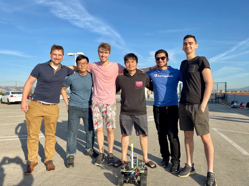
The Testla project is the culmination of our efforts to create an autonomously operated RC Car by pooling together our experience in software design, hardware design, power systems, and mobile application development. Project development started in February of 2022 and ended in May.
Introduction
The project was divided into 5 modules:
- Sensor Information
- Motor Operation
- Geological Information
- Driver & LCD Manager
- Bridge & Android Application
Team Members & Responsibilities
- Devin Alexander Gitlab
- Leader
- Geographical Controller
- Master Controller
- Sinan Bayati Gitlab
- PCB Design
- Motor Controller
- Michael Hatzikokolakis Gitlab
- Co-Leader
- Motor Controller
- Testing
- Scott LoCascio Gitlab
- Geographical Controller
- Car Construction
- Testing
- Thinh Lu Gitlab
- Android Application
- Sensor and Bridge Controller
- Bang Nguyen Gitlab
- Sensor and Bridge Controller
- LCD Display
Schedule
| Description | Color |
|---|---|
| General | Black |
| Bridge & Mobile App | Blue |
| Driver | Orange |
| GEO | Green |
| Motor | Red |
| Sensor | Violet |
| Week # | Start Date | End Date | Task | Status |
|---|---|---|---|---|
| 1 | 2/15/2022 | 2/21/2022 |
|
Complete |
| 2 | 2/22/2022 | 2/28/2022 |
|
Complete |
| 3 | 3/1/2022 | 3/7/2022 |
|
Complete |
| 4 | 3/8/2022 | 3/14/2022 |
|
Complete |
| 5 | 3/15/2022 | 3/21/2022 |
|
Complete |
| 6 | 3/22/2022 | 3/28/2022 |
|
Complete |
| 7 | 3/29/2022 | 4/4/2022 |
|
Complete |
| 8 | 4/5/2022 | 4/11/2022 |
|
Complete |
| 9 | 4/12/2022 | 4/18/2022 |
|
Complete |
| 10 | 4/19/2022 | 4/25/2022 |
|
Complete |
| 11 | 4/26/2022 | 5/2/2022 |
|
Complete |
| 12 | 5/3/2022 | 5/9/2022 |
|
Complete |
| 13 | 5/10/2022 | 5/16/2022 |
|
Complete |
| 14 | 5/17/2022 | 5/25/2022 |
|
Complete |
Parts List & Cost
| Item# | Part Desciption | Vendor | Qty | Cost/Item |
|---|---|---|---|---|
| 1 | Unassembled RC Car | Traxxas [1] | 1 | $279.99 |
| 2 | CAN Transceivers | Amazon [2] | 4 | $8.99 |
| 3 | PCB | JLCPCB [3] | 1 | $40.00 |
| 4 | Sensors | DFRobot [4] | 4 | $12.90 |
| 5 | GPS | Amazon [5] | 1 | $29.92 |
| 6 | RPM Sensor | Traxxas [6] | 1 | $19.00 |
Printed Circuit Board
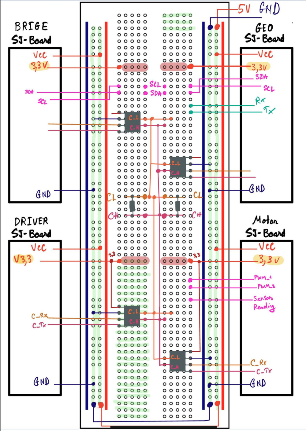
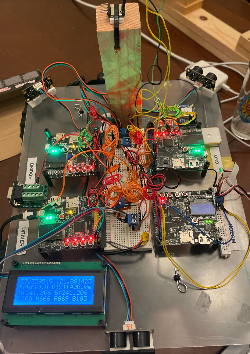
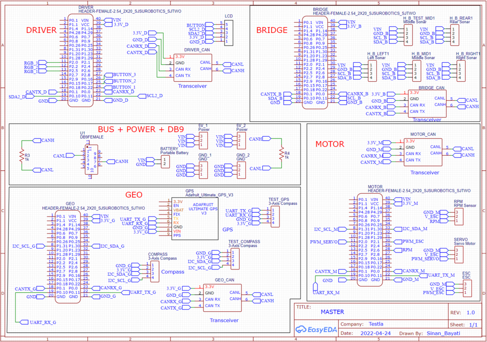
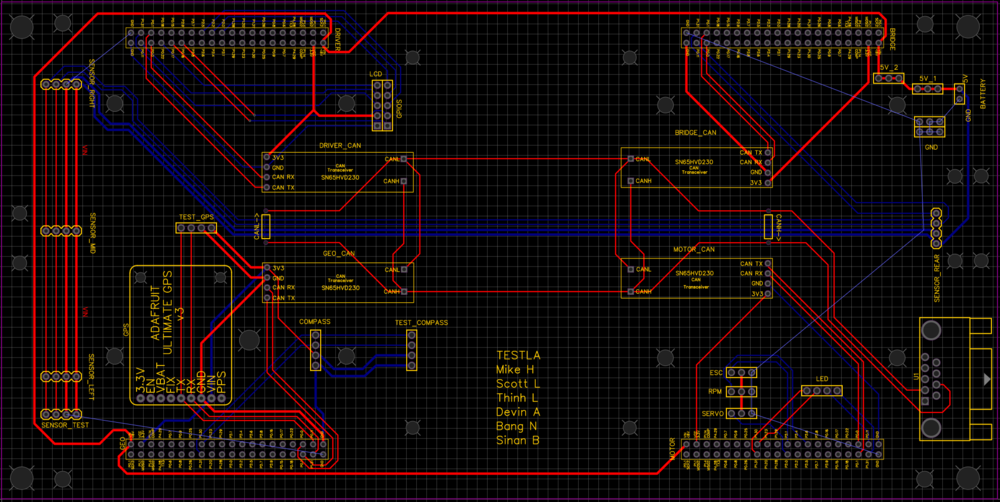
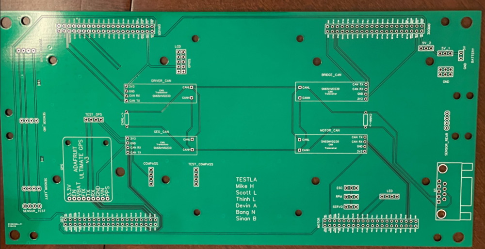
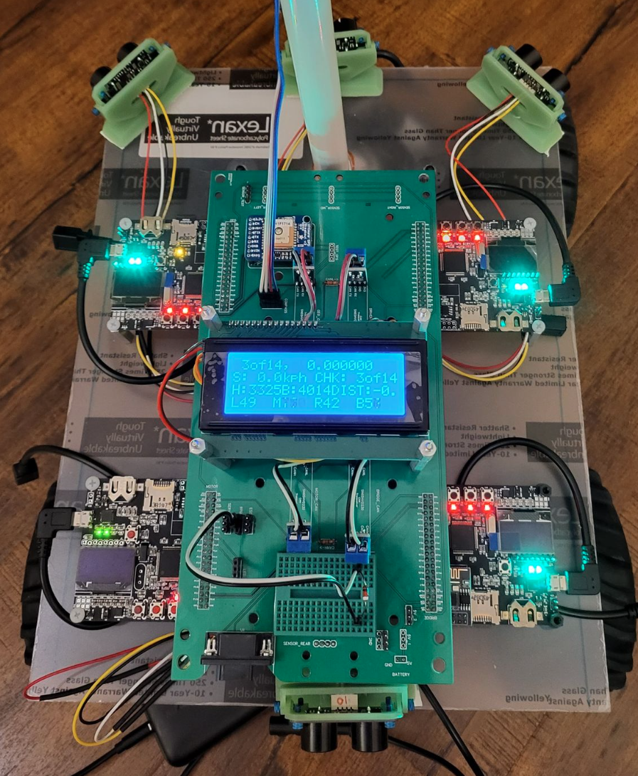
The preliminary design consisted of neatly routes wires on a breadboard connecting all the various components. It still looked confusing due to the sheer amount of connections that had to be made, this complexity was to be handled by a custom PCB designed in EasyEDA.
Challenges
We found that some wires we used were faulty and were not conducting electricity properly. This resulted in a lot of time spent physically debugging connections. To avoid this type of scenario, a continuity check with a multimeter to ensure wire integrity can be performed. We chose to design a PCB to provide a clean look to the car and have higher pin connection strength, as bread board connections tend to be less reliable.
The design has many holes for mounting and pinouts for various peripherals (GPS, LCD, Buttons, etc.)
Steps to design PCB: Following this general guideline will help you avoid any obstacles.
- Finish preliminary breadboard wiring and track changes along the way
- Identify desired mounting topology and make measurements
- Use PCB software to make schematic diagram (not PCB wiring)
- Make holes in the PCB for desired mounting locations (the more the merrier)
- Start positioning the components, then begin making traces
CAN Communication
<Talk about your message IDs or communication strategy, such as periodic transmission, MIA management etc.>
Hardware Design
<Show your CAN bus hardware design>
DBC File
VERSION ""

NS_ :
	BA_
	BA_DEF_
	BA_DEF_DEF_
	BA_DEF_DEF_REL_
	BA_DEF_REL_
	BA_DEF_SGTYPE_
	BA_REL_
	BA_SGTYPE_
	BO_TX_BU_
	BU_BO_REL_
	BU_EV_REL_
	BU_SG_REL_
	CAT_
	CAT_DEF_
	CM_
	ENVVAR_DATA_
	EV_DATA_
	FILTER
	NS_DESC_
	SGTYPE_
	SGTYPE_VAL_
	SG_MUL_VAL_
	SIGTYPE_VALTYPE_
	SIG_GROUP_
	SIG_TYPE_REF_
	SIG_VALTYPE_
	VAL_
	VAL_TABLE_

BS_:

BU_: DRIVER MOTOR SENSOR GEO DEBUG


BO_ 100 DRIVER_HEARTBEAT: 3 DRIVER
 SG_ DRIVER_HEARTBEAT_cmd : 0|8@1+ (1,0) [0|0] "" DBG

BO_ 110 DRIVER_STEERING: 3 DRIVER
 SG_ DRIVER_STEERING_yaw : 0|12@1+ (0.001,-2) [-10|10] "radians" MOTOR
 SG_ DRIVER_STEERING_velocity : 12|12@1+ (0.01,-20) [-20|20] "kph" MOTOR

BO_ 120 MOTOR_HEARTBEAT: 5 MOTOR
 SG_ MOTOR_HEARTBEAT_speed_raw : 0|8@1+ (1,0) [0|0] "count" DEBUG
 SG_ MOTOR_HEARTBEAT_speed_rpm : 8|10@1+ (1,0) [0|0] "rpm" DEBUG
 SG_ MOTOR_HEARTBEAT_speed_kph : 18|10@1+ (0.1,-10) [-10|10] "kph" DEBUG
 SG_ MOTOR_HEARTBEAT_angle_duty : 28|10@1+ (0.001,-2) [-10|10] "duty" MOTOR


BO_ 125 MOTOR_DEBUG: 8 MOTOR
 SG_ MOTOR_DEBUG_speed_target : 0|26@1+ (0.1,-10) [-10|10] "kph" DEBUG
 SG_ MOTOR_DEBUG_speed_kph : 26|10@1+ (0.1,-10) [-10|10] "kph" DEBUG
 SG_ MOTOR_DEBUG_speed_duty : 36|10@1+ (0.1,0) [0|0] "duty" DEBUG
 SG_ MOTOR_DEBUG_integral_error : 46|10@1+ (0.1,-10) [-10|10] "error" DEBUG
 SG_ MOTOR_DEBUG_current_state : 56|3@1+ (1,0) [0|5] "state" DEBUG
 SG_ MOTOR_DEBUG_next_state : 59|3@1+ (1,0) [0|5] "state" DEBUG


BO_ 128 MOTOR_ESC_CALIBRATED: 1 MOTOR
 SG_ MOTOR_ESC_CALIBRATED_calibration_status : 0|4@1+ (1,0) [0|3] "esc_calibration_e" DRIVER
 SG_ MOTOR_ESC_CALIBRATED_start_calibration_ack_to_driver : 4|1@1+ (1,0) [0|1] "bool" DRIVER


BO_ 129 DRIVER_START_ESC_CALIBRATION: 1 DRIVER
 SG_ MOTOR_ESC_CALIBRATED_begin_esc_calibration : 0|1@1+ (1,0) [0|3] "bool" MOTOR

BO_ 130 MOTOR_ACK: 1 MOTOR
 SG_ MOTOR_ACK_cmd : 0|8@1+ (1,0) [0|0] "" DRIVER


BO_ 200 SENSOR_SONARS: 8 SENSOR
 SG_ SENSOR_SONARS_left : 0|10@1+ (1,0) [0|800] "inch" DRIVER
 SG_ SENSOR_SONARS_right : 10|10@1+ (1,0) [0|0] "inch" DRIVER
 SG_ SENSOR_SONARS_middle : 20|10@1+ (1,0) [0|0] "inch" DRIVER
 SG_ SENSOR_SONARS_back : 30|10@1+ (1,0) [0|0] "inch" DRIVER
 SG_ SENSOR_SONARS_frame_id : 42|16@1+ (1,0) [0|0] "" DRIVER

BO_ 210 SENSOR_DESTINATION_LOCATION: 8 SENSOR
 SG_ SENSOR_DESTINATION_latitude : 0|28@1+ (0.000001,-90.000000) [-90|90] "Degrees" GEO
 SG_ SENSOR_DESTINATION_longitude : 28|28@1+ (0.000001,-180.000000) [-180|180] "Degrees" GEO

BO_ 218 NAVIGATION_MESSAGE: 1 GEO
 SG_ NAVIGATION_STATUS_navigation_status : 0|8@1+ (1,0) [0|3] "navigation_status_e" DRIVER

BO_ 219 CHECKPOINT_MESSAGE: 8 GEO
 SG_ CHECKPOINT_MESSAGE_compass_heading : 0|12@1+ (1,0) [0|359] "Degrees" DRIVER
 SG_ CHECKPOINT_MESSAGE_destination_bearing : 12|12@1+ (1,0) [0|359] "Degrees" DRIVER
 SG_ CHECKPOINT_MESSAGE_destination_distance : 24|16@1+ (0.1,0) [0|0] "Meters" DRIVER
 SG_ CHECKPOINT_MESSAGE_curr_checkpoint_num : 40|8@1+ (1,0) [0|255] "Integer" DRIVER
 SG_ CHECKPOINT_MESSAGE_total_checkpoint_num : 48|8@1+ (1,0) [0|255] "Integer" DRIVER
 SG_ CHECKPOINT_MESSAGE_checkpoint_status : 56|8@1+ (1,0) [0|3] "checkpoint_status_e" DRIVER

BO_ 220 GEO_STATUS: 8 GEO
 SG_ GEO_STATUS_compass_heading : 0|12@1+ (1,0) [0|359] "Degrees" DRIVER
 SG_ GEO_STATUS_destination_bearing : 12|12@1+ (1,0) [0|359] "Degrees" DRIVER
 SG_ GEO_STATUS_destination_distance : 24|16@1+ (0.1,0) [0|0] "Meters" DRIVER

BO_ 520 DEBUG_GPS_CURRENT_LOCATION: 8 GEO
 SG_ DEBUG_GPS_CURRENT_LOCATION_latitude : 0|28@1+ (0.000001,-90.000000) [-90|90] "Degrees" DEBUG
 SG_ DEBUG_GPS_CURRENT_LOCATION_longitude : 28|28@1+ (0.000001,-180.000000) [-180|180] "Degrees" DEBUG
 SG_ DEBUG_GPS_CURRENT_LOCATION_fix : 56|2@1+ (1,0) [0|2] "" DEBUG

BO_ 521 DEBUG_GEO_GPS_UPDATE: 8 GEO
 SG_ DEBUG_GEO_GPS_UPDATE_count : 0|16@1+ (1,0) [0|0] "" DEBUG
 SG_ DEBUG_GEO_GPS_UPDATE_max_period : 16|16@1+ (1,0) [0|0] "milliseconds" DEBUG
 SG_ DEBUG_GEO_GPS_UPDATE_min_period : 32|16@1+ (1,0) [0|0] "milliseconds" DEBUG
 SG_ DEBUG_GEO_GPS_UPDATE_average_period : 48|16@1+ (1,0) [0|0] "milliseconds" DEBUG

BO_ 522 DEBUG_GEO_COMPASS_UPDATE: 8 GEO
 SG_ DEBUG_GEO_COMPASS_UPDATE_count : 0|16@1+ (1,0) [0|0] "" DEBUG
 SG_ DEBUG_GEO_COMPASS_UPDATE_max_period : 16|16@1+ (1,0) [0|0] "milliseconds" DEBUG
 SG_ DEBUG_GEO_COMPASS_UPDATE_min_period : 32|16@1+ (1,0) [0|0] "milliseconds" DEBUG
 SG_ DEBUG_GEO_COMPASS_UPDATE_average_period : 48|16@1+ (1,0) [0|0] "milliseconds" DEBUG

CM_ BU_ DRIVER "The driver controller driving the car";
CM_ BU_ MOTOR "The motor controller of the car";
CM_ BU_ SENSOR "The sensor controller of the car";
CM_ BU_ GEO "the geographical controller of the car";
CM_ BU_ DEBUG "the debug topic that all controllers can publish to";
CM_ BO_ 100 "Sync message used to synchronize the controllers";
CM_ SG_ 100 DRIVER_HEARTBEAT_cmd "Heartbeat command from the driver";

BA_DEF_ "BusType" STRING ;
BA_DEF_ BO_ "GenMsgCycleTime" INT 0 0;
BA_DEF_ SG_ "FieldType" STRING ;

BA_DEF_DEF_ "BusType" "CAN";
BA_DEF_DEF_ "FieldType" "";
BA_DEF_DEF_ "GenMsgCycleTime" 0;

BA_ "GenMsgCycleTime" BO_ 100 1000;
BA_ "GenMsgCycleTime" BO_ 200 50;
BA_ "FieldType" SG_ 100 DRIVER_HEARTBEAT_cmd "DRIVER_HEARTBEAT_cmd";

VAL_ 100 DRIVER_HEARTBEAT_cmd 2 "DRIVER_HEARTBEAT_cmd_REBOOT" 1 "DRIVER_HEARTBEAT_cmd_SYNC" 0 "DRIVER_HEARTBEAT_cmd_NOOP" ;
Sensor & LCD
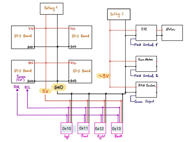
Sensor Hardware Design ( SJ-2 Bridge Control Board)
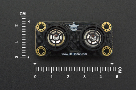
- Ultra-Sonic Sensor URM09 (I2C Protocol)
• Supply Voltage: 3.3~5.5V DC • Operating Current: 20mA • Operating Temperature Range: -10℃~+70℃ • Measurement Range: 2cm~500cm (can be set) • Resolution: 1cm • Accuracy: 1% • Frequency: 50Hz Max • Dimension: 47mm × 22 mm/1.85” × 0.87”
Sensor Software Design
- Low level - peripheral driver
- Peripheral Initialize function
- I2C Clock 100KHz
- I2C Pin:
- SCL: P0_10
- SDA: P0_11
- I2C single byte read function
- Input parameter
- Slave address (7-bit + R/W-bit)
- Register address (1 byte)
- Output parameter
- Register value (1 byte)
- Return true if success else return false
- Input parameter
- I2C single byte write function
- Input parameter
- Slave address (7-bit + R\W bit)
- Register address (1 byte)
- Written value (1 byte)
- Return true if success else return false
- Input parameter
- Peripheral Initialize function
- Mid-level -sensor
- Defined data struct
- Sonar_sensor__sample_sum_s
- Left
- Middle
- Right
- Back
- Sonar_sensor__sample_queue_s
- Left
- Middle
- Right
- Back
- Sonar_sensor__address_e
- Left (7-bits - 0x26)
- Middle (7-bits – 0x22)
- Right (7-bits – 0x24)
- Back (7-bits – 0x20)
- Sonar_sensor_measure_mode_e
- Automatic
- Passive
- Sonar_sensor__measure_range_e
- 150 cm
- 300 cm
- 500 cm
- Sonar_sensor__sample_sum_s
- Initialize sensor function
- Init I2C peripheral
- Init all the sensors with the following configurations:
- Passive measure mode
- 150 cm range
- Sensor collects sample function
- To avoid the sensor's crosstalk, we implement the following sequence
- Start the measurement left sensor
- Delay 25ms
- Collect data from the left sensor
- Start the measurement right sensor
- Delay 25ms
- Collect data from the right sensor
- Start the measurement back and middle
- Delay 25ms
- Collect data from the back and middle sensor
- To avoid the sensor's crosstalk, we implement the following sequence
Sensor Technical Challenges
- Issue: we cannot read or write on the default address.
- Reason: After using the logical analyzer, we realize the init clock at 400Khz was too fast for this sensor even though the datasheet did not mention it.
- Solution: we reduce the I2C Clock speed to 100kHz
- Issue: These nearby ultra-sonic sensors receive each other’s bounce-back signal.
- Reason: We config the sensor in automatic mode, and it causes the sensors to crosstalk.
- Solution: we config the sensor in passive mode and tested them with many test cases to come up with the best sequence, and the sensor must operate at 10hz frequency.
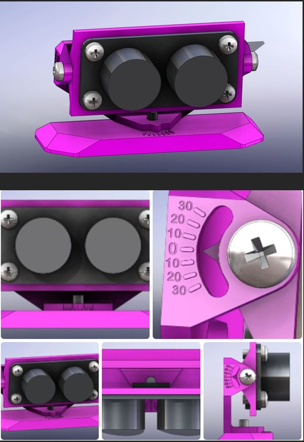
- Issue: Sensor noise is getting worse with bad mounting
- Reason: the sensors are mounted with the bean down to the ground.
- Solution: we come to design a mechanical mount with the ability of 60 degrees horizontal and vertical adjustment
Motor ECU
Hardware Design
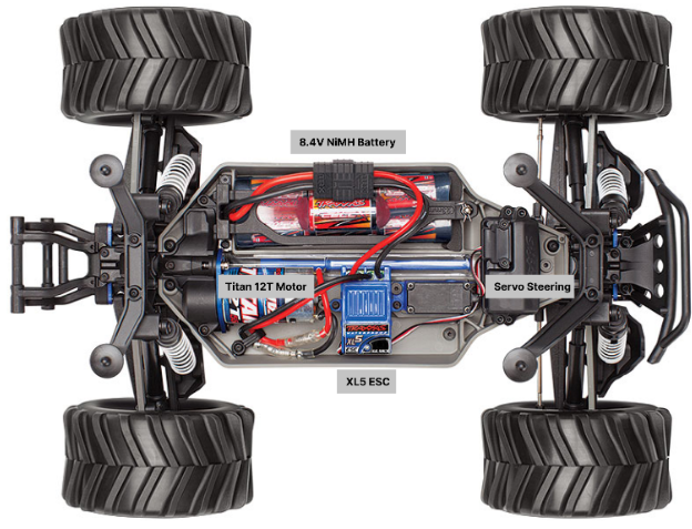
A single SJ2-C board was placed in charge of handling all interactions with the Traxxas parts. This included an ESC (Electronic Speed Control) connected to a brushed DC motor, a servo motor for steering control, and a wheel encoder installed adjacent to the gear shaft (CHECK).
Defining Signals
While Traxxas does provide support for hobby RC car enthusiasts, they do not provide clear documentation on signal inputs and outputs to all of their electrical components. To understand what signals would need to be generated by the SJ2-C, the output of the receiver was intercepted. Manipulating the Traxxas remote would generate PWM signals at the output of the receiver. By reading these signals on an oscilloscope, it was determined that both the ESC and servo motor both operated with a 100 Hz PWM signal on a range of duty cycles between 10 - 20%.
- For the ESC: 10% DC = full reverse speed, 15% DC = idle/zero speed, 20% DC - full forward speed
- For the servo motor: 10% DC = wheels fully turned to the left, 15% DC = wheels turned straight ahead, 20% DC = wheels turned fully to the right.
Setting up the PWM channels
The PWM channels on pins P2.0 and P2.1 were both enabled on single edge mode at a frequency of 100 Hz with a duty cycle of 15%. Initial tests were conducted by mapping the buttons of the SJ2-C to modifying the duty cycles on both PWM channels. These tests were successful in changing the motor speed and wheel direction.
RPM Sensor
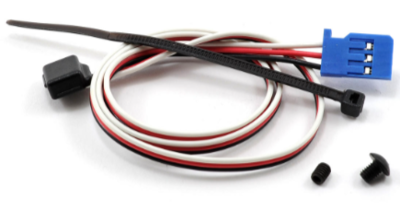
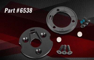
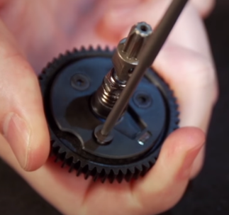
In order to give real-time feedback on the speed the car is traveling at, an RPM sensor was installed. For ease of compatibility, the Traxxas 6520 RPM Sensor (long variant) was purchased for this task. It was installed with the Traxxas 6538 Telemetry Trigger Magnet Holder for Spur Gear by following this tutorial. While this was expected to provide proper signal output with no extra components, initial testing of the sensor yielded an 0.4 Vpp signal comprised of an unstable, noisy signal. Doing further research led us to find that a 1kΩ pull-up resistor connecting the data pin to a 3.3V rail was required to pull the signal high instead of letting it float. This corrected the output signal to give the expected result.
SJ2-C LED Breakdown
Normal Operation:
- LED 0: Toggle on CAN receive
- LED 1: Toggle on CAN transmit
- LED 2: Unused
- LED 3: Driver signal Missing-in-Action
ESC Calibration
- LEDs 0-2: Used to detail current step in calibration process
- LED 3: Unused
SJ2-C Switch Breakdown
- SW 0: Start ESC Calibration Sequence
- SW 1: Disable Motor
- SW 2: Disable Steering
- SW 3: Enable both Motor and Steering
(Note: Motor and Steering are disabled on startup by default)
Software Design
CAN Bus Interactions
The Motor Controller receives two different values from the Driver Controller: an angle to turn the wheels to (DRIVER_STEERING__yaw) and the speed at which to drive (DRIVER_STEERING__velocity).
The Motor Controller sends a multitude of signals addressed to “Debug”, as well as one signal to the Driver pertaining to the status of ESC calibration. These debug signals include a variety of formats of the current speed given by the RPM sensor, the error calculation used in the PID logic, and the operations of the state machine within the motor logic handler.
RPM Sensor
With a proper data output from the sensor, the output was attached to pin 2.6 (CAP0) for operation with Timer2. The initial plan was to measure the time between pulses and perform calculations to extrapolate the current speed, but another unexpected issue was experienced. When configuring the interrupt handler on the pin in either rising-edge or falling-edge detection, the interrupt handler would be triggered repeatedly on what appeared to be a steady low signal. This was observed by configuring Bus Master to show the interrupt count in combination with viewing a logic analyzer to see the signal state. This was especially concerning as it was noticed that if the car wheels stopped turning at a specific position, the sensor would permanently hold a low signal until further rotation occurred, causing even more potential for inaccuracy in any given speed reading. After hours of trying different interrupt configuration settings, efforts to find a direct solution were put on pause. A workaround was discovered by essentially disregarding any interrupts that were deemed to be physically too fast to have been caused by the actual rotation of the tires. This resulted in proper software operation of the interrupt handler, but it required a new method for ascertaining the speed. The final implementation revolved around counting the amount of sensor pulses within a 5 Hz window. This timing was specifically chosen as a compromise between two tradeoffs. A quicker window would allow for faster updates to the ESC, but a slower window would allow for more pulse data collection and higher accuracy.
PID Controller
While an objective of the car is to implement a “PID” controller, in reality a simple “P” controller is enough for an effective control system. This means that all that is needed is the target speed, the current speed, and a gain factor. If the current speed is far from the target speed, a higher error value is produced. When multiplied with the gain, this results in the car making larger changes to its speed to reach the target speed, while using smaller changes to modulate the speed as forces on the car change due to varying terrain or surface angle changes.
 // -------------Error Calculations-------------//
 if (next_state == FORWARD) {
   error = target_motor__kph - current_speed;
 } else if (next_state == REVERSE) {
   error = target_motor__kph + current_speed;
 }
 } else if (next_state == FORWARD) {
   speed_for_motor__kph += gain * error;
 }
ESC Calibration
When demoing the second prototype, the ESC fell out of calibration for the first time in operation. This created an undesirable situation where the Traxxas receiver had to be connected back to the motor so it could be calibrated with the Traxxas remote. This led to the need for the calibration sequence to be programmable from the board with no need to rewire components. It was observed that to calibrate the ESC, the remote trigger would need to follow a certain procedure: Neutral position Full forward speed Full reverse speed Neutral position This procedure was copied by the Motor Controller with a preparation delay inserted into the beginning of the sequence and can be activated by pressing switch 0 at any time. Note that the ESC should be placed in calibration mode just after pressing switch 0. Failure to do so could cause the car to attempt to reach its maximum speed and hold it for two seconds.
State Machine
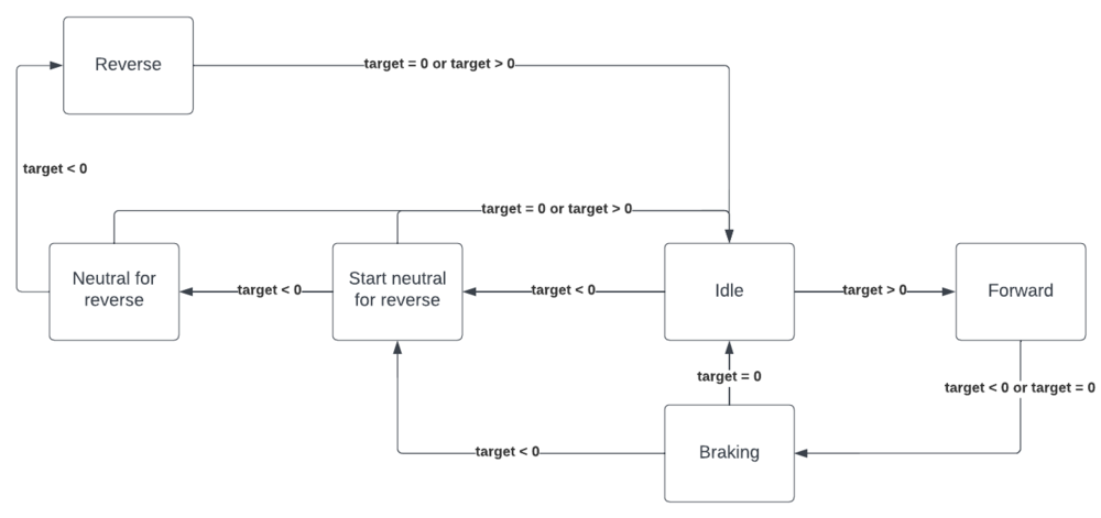
The final version of the Motor Controller logic included a state machine:
Each state is defined in the following enumeration:
typedef enum {
  IDLE = 0,
  FORWARD = 1,
  BRAKING = 2,
  START_NEUTRAL_FOR_REVERSE = 3,
  NEUTRAL_FOR_REVERSE = 4,
  REVERSE = 5,
} CAR_MOTION_STATUS;
Things to note:
- Braking is the same as sending a reverse signal to the ESC. This is different from sending an idle signal that stops applying current to the motor and allows the car to coast to a halt.
- The START_NEUTRAL_FOR_REVERSE, NEUTRAL_FOR_REVERSE, and REVERSE states are all necessary for the car to perform reverse motion if the car had been moving forward just prior.
The state machine starts by checking the speed the Driver Controller wants to obtain. This can be one of three states: 0 speed, forward speed, or reverse speed:
if (target_motor__kph >= -0.1f && target_motor__kph <= 0.1f) {
  ...
} else if (target_motor__kph > 0.1f) {
  ...
} else if (target_motor__kph < -0.1f) {
  ...
}
Within a speed value, the current state is checked and the next state is assigned based off of this. There's coverage for every case here, as the car should be able to go from any state to any state.
if (target_motor__kph >= -0.1f && target_motor__kph <= 0.1f) {
   if (current_state == IDLE) {
     next_state = IDLE;
   } else if (current_state == FORWARD) {
     next_state = BRAKING;
   } else if (current_state == BRAKING) {
     if (current_speed >= -0.1f && current_speed <= 0.1f) {
       next_state = IDLE;
     } else {
       next_state = BRAKING;
     }
   } else if (current_state == START_NEUTRAL_FOR_REVERSE) {
     next_state = IDLE;
   } else if (current_state == NEUTRAL_FOR_REVERSE) {
     next_state = IDLE;
   } else if (current_state == REVERSE) {
     next_state = IDLE;
   }
}
Technical Challenges
- RPM Sensor gave low voltage, improper signal (see: Hardware Design - RPM Sensor)
- Interrupt handler generated interrupts on stable signal (see: Software Design - RPM Sensor)
- ESC would require calibration on startup every time - Sending a neutral signal (15% Duty Cycle) to the ESC for the first three seconds gave the ESC a signal to lock on to and not require calibration
Geographical Controller
The geographical (geo) controller is used to provide the vehicle with a sense of location. To do this, the controller is interfaced to a compass which provides a heading, and a GPS module which provides a latitude, longitude, and GPS fix. GPS fix indicates that the GPS unit is connected to enough sattelites to provide accurate location data. The controller reads a destination off the CAN bus and calculates the distance from its current position. Additionally, it calculates a bearing, which is the degrees from north that the car must point to be facing the destination. If the car aligns its heading with the bearing and drives in a straight line for the number of meters described by the distance calculation, then the car will arrive at its destination.
However, the vehicle will not be driving in a straight line because of obstacle avoidance. To deal with this, the distance and bearing are updated regularly at a rate of 10Hz. When an obstacle forces the vehicle to deviate from the desired course, it will recalculate the bearing and distance from its new location. This distance and location is then broadcast on the CAN bus, and digested by the driver controller.
Hardware Design
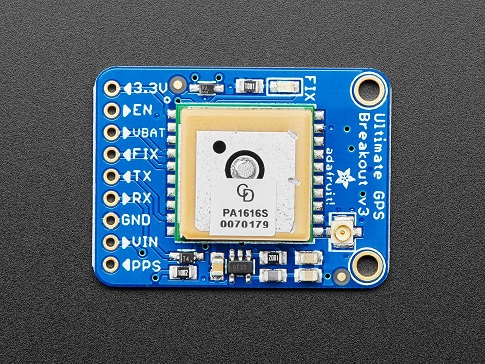
An Adafruit Ultimate GPS breakout module using the MTK3339 chipset is interfaced over UART to the Geographical controller to provide latitude and longitude updates.
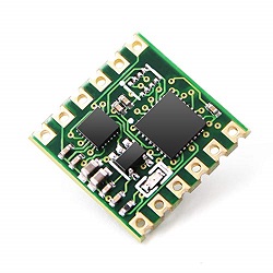
A Witmotion WT901 IMU is connected over I2C to provide access to the vehicles heading.
Software Design
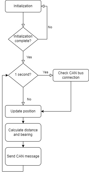
The general software flow is shown in the diagram below. This loop is run in a 10Hz periodic callback set up in FreeRTOS.
Initialization
On startup the GPS module is configured. The GPS module sends data at 9600 bps after powering on but must be set to 115200 bps to support 10Hz updates. The controller must send a command to increase the GPS module's baud rate then change the baud rate on its own UART interface. Initially, the GPS sends out several different NMEA strings on every update. The vehicle only needs latitude , longitude and GPS fix data so the GPS is configured to only send GPGGA strings. This prevents the geo controller from wasting time to intake data that it is uninterested in. Finally, the GPS module is configured to send updated data at a rate of 10Hz. After this process is complete, the controller enters its main loop.
Main Loop
The geo controller runs at a frequency of 10Hz. A FreeRTOS task uses vTaskDelayUntil() to define a finite period of 100 milliseconds between invocations of the periodic callback.
The GPS module is read by reading characters out of the UART into a line buffer. If a full line has been deposited into the buffer then the latitude, longitude and GPS Fix are updated. Additionally, a min and max time between GPS updates field is filled in as well as a count of updates. This debug information is published on the bus to analyze fidelity of the module.
Next, the compass is read over an I2C interface to acquire the heading. The WT901 is an IMU which actually has a good deal more information available besides heading. Currently we are only reading the compass heading but can expand expand in the future to read acceleration and orientation. This module does need to be calibrated one time to ensure it is correctly reporting the heading. The module has a UART interface which can be used to interface between a TTL to USB converter to a software suite. This software can also be used for debugging and calibration.
After reading the position the CAN interface checks if there are any changes to the destination being published by the bridge controller. After obtaining the most recent desired destination, the geographical module is invoked to calculate a distance and bearing. The section below goes into more detail on the geo calculation. After a distance and bearing are calculated, they are published onto the bis along with the current heading and dubug information.
Geo process
The desired and current position are used to calculate a distance and bearing using the haversine formula shown below.
Distance
Bearing
Moveable Type Scripts: Calculate distance, bearing and more between Latitude/Longitude points
Technical Challenges
There were several challenges in developing a reliable geographical controller.
Initially, connecting to the GPS was a challenge because the format of the ASCII lines were not well understood.
Expected string
$GPGGA,064951.000,2307.1256,N,12016.4438,E,1,8,0.95,39.9,M,17.8,M,,*65
Actual string
$GPGGA,,,,,,,5,,,,M,,*65
There were also issues with verifying that the command strings being sent were achieving their desired results
Both these problems were solved by attaching the tx line of the GPS to an oscilloscope and decoding the UART messages. This allowed us to fully characterize the output of the GPS and its response to command strings.
LCD & Communication Bridge Controller
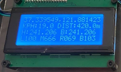
LCD Hardware Design
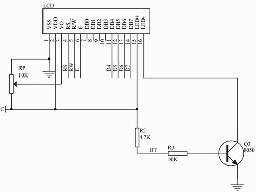
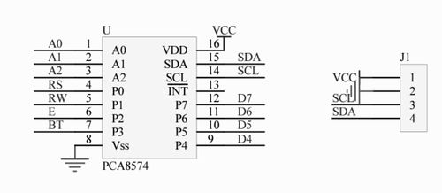
LCD Circuit with 8-bit I/O expander for I2C-bus
LCD Software Design ( SJ2- Driver Board)
- Low level - peripheral driver
- Peripheral Initialize function
- I2C Clock 400KHz
- I2C Pin:
- SCL: P0_10
- SDA: P0_11
- I2C single byte write function
- Input parameter
- Slave address (7-bit + R\W bit)
- Register address (dummy byte - we always write directly into VRAM )
- Written value (1 byte)
- Return true if success else return false
- Input parameter
- Peripheral Initialize function
- Toggle Enable Pin Function
- Input parameter
- byte value
- Input parameter
- Toggle Enable Pin Function
- Mid-level - LCD driver Command Byte vs Data Byte
- Transfer command byte function
- Input parameter
- byte value
- Input parameter
- Transfer command byte function
- Transfer data byte function
- Input parameter
- byte value
- Input parameter
- Transfer data byte function
- High-level - LCD driver
- LCD init function ( backlight ON )
- Input parameter
- Colum
- Row
- Character Size
- Input parameter
- LCD init function ( backlight ON )
- LCD clear function
- LCD clear particular location function
- Input parameter
- Start Colum
- Start Row
- Number of character need to clear
- Input parameter
- LCD clear particular location function
- LCD set cursor location function
- Input parameter
- Start Colum
- Start Row
- Input parameter
- LCD set cursor location function
- LCD print char function
- Input parameter
- Start Colum
- Start Row
- Pointer to first index of char array
- Input parameter
- LCD print char function
Bridge Controller
The Bridge Controller is used to establish wireless communication between our vehicle and mobile app. This is a bi-directional communication where the bridge controller will send vehicle states (GPS location, heading, speed & sensor data) to the mobile app, and also receive command messages (gps destination) to broadcast back to the vehicle CAN bus. We decided to use an ESP8266 to connect the bridge controller to the local WIFI network. We picked ESP8266 because SJTwo board already provides an open slot to install this module. Instead of connecting the vehicle directly to the mobile app which may require managing low-level network sockets on mobile devices, we use a NodeJS server as a mediator to maintain a more reliable communication between these two end-points. This design decision also makes it possible to monitor the vehicle state and send commands from multiple devices at the same time.
Bridge Hardware Design
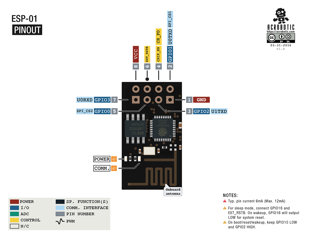
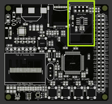 ESP-8266 (ESP-01) slot on SJTwo board
The ESP-8266 is a low-cost WIFI with a built-in TCP/IP software stack. ESP-8266 is connected to the SJTwo board via UART3. SJ-Two board communicates with ESP8266 using AT Command Set Interface.
Bridge Software Design
There are two key components in our setup for the bridge controller: Local Bridge Node Remote Server Our local bridge node is a FreeRTOS task that runs continuously (with a 100ms sleep period). When being run, the task will start by performing an initialization sequence on ESP8266. When a WIFI connection is established, the bridge node will use new data collected from the CAN bus to compose a new message and send it to the server via a TCP/IP socket. Along with that, the task also monitors the current status of this TCP/IP connection and network status and attempts to reconnect whenever the connection dropped for any reason. The remote server is a NodeJS server running on an AWS EC2 instance. The server accepts raw TCP/IP communication with the local bridge node and broadcasts the data to any clients via topic channels (‘location’, ‘sensor’, ‘steering’, etc.) powered by socket.io. Since the local bridge node runs periodically at around 2Hz, we make use of the server response message as a way to send commands back to the bridge node. With this approach, we don’t have to configure ESP8266 as a server and create another TCP/IP socket just for sending commands from the server back to the local bridge node.
Technical Challenges
When implementing the bridge controller with the provided ESP-32 library, our board was reset occasionally due to the retry-and-timeout mechanism for sending TCP/IP packets more reliably. We were able to bypass this issue by running the bridge controller as an independent FreeRTOS task instead of running it inside the periodic scheduler.
Master Module
<Picture and link to Gitlab>
Hardware Design
Software Design
The main software design for the master controller comprises of taking in communication from all of the other controllers on the bus in order to figure out the status of the car and act accordingly.
The purpose of the master controller’s branch of logic is for it to be used for responding to navigation sequences that are established by Bridge and Geo controller. From this, we can explain that there are two main branches of the car’s driver logic: Obstacle Avoidance Logic and Navigation to the Next Checkpoint logic.
In Obstacle Avoidance mode, the main objective is for the car to avoid crashing into obstacles such as people, walls, etc throughout the course of the navigation sequence. This logic branch triggers only when there is a threshold of 0, 1, or 2 for any of the front sensors.
In Navigation Towards next checkpoint mode, the car will navigate towards the next checkpoint until there are no checkpoints left. It will only do this if there are sensor readings above 150cm. If an object is detected at threshold 3, the car can still navigate towards the target, but it will do so at half of the speed so that it can apply breaks prematurely to help it avoid obstacles more smoothly.
The way that we read the sensor thresholds is that we use 4 different values, 25cm for sensor threshold 0, 50cm for sensor threshold 1, 135cm for sensor threshold 2, and 149cm for sensor threshold 3.
/// Check sensor values against defined constant thresholds and return bitfields for sensors corresponding to the convention below.
 /// Helper function called by all 4 function above to provide required output value using (0b0000BRML) bit convention
 obstacle_detected_on_sensors_e driver__helper_check_sensors_under_OBJECT_THRESHOLD_N(uint16_t left_sensor, uint16_t middle_sensor, uint16_t right_sensor, uint16_t back_sensor, uint16_t threshold) {
   obstacle_detected_on_sensors_e ret_sensors_trig = no_sensor_triggered; // Init to 0 for no obstacles detected
   // Sensor Bitmasks
   const uint8_t no_sensor_bitmask = 0b00000000;
   const uint8_t left_sensor_bitmask = 0b00000001;
   const uint8_t middle_sensor_bitmask = 0b00000010;
   const uint8_t right_sensor_bitmask = 0b00000100;
   const uint8_t back_sensor_bitmask = 0b00001000;
   // Bitwise OR each sensor below threshold passed in with it's respective bitmask
   ret_sensors_trig |= (left_sensor < threshold) ? left_sensor_bitmask : no_sensor_bitmask;
   ret_sensors_trig |= (middle_sensor < threshold) ? middle_sensor_bitmask : no_sensor_bitmask;
   ret_sensors_trig |= (right_sensor < threshold) ? right_sensor_bitmask : no_sensor_bitmask;
   ret_sensors_trig |= (back_sensor < threshold) ? back_sensor_bitmask : no_sensor_bitmask;
   return ret_sensors_trig;
 }
Technical Challenges
< List of problems and their detailed resolutions>
Mobile Application
Software Design
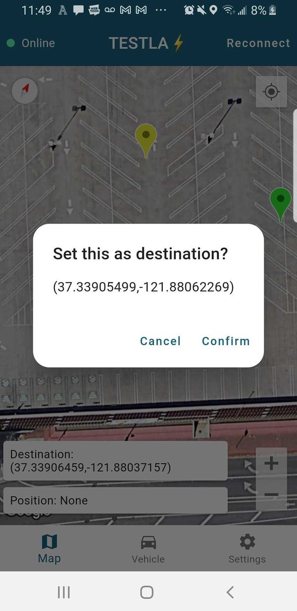
Our mobile app was developed using Flutter framework. We were able to release both Android and iOS version. The app is connected to our AWS server using Socket.IO and continue to listen to topics related to the vehicle. Whenever user select a new destination on the map, the app will send a new command message to server so that the new destination will be sent to the bridge controller.
Conclusion
Testla, at its simplest, is a combination of four micro-controllers on an RC car chassis to accomplish autonomous driving. To drive autonomously there are several necessary components: local real-time awareness, big picture planning, actuation, and limited human input.
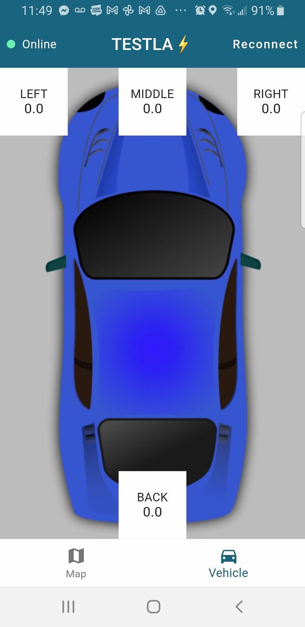
Local real-time awareness in this project is handled by the sonar sensor array, geo controller and driver controller. This pathway takes in immediate, on the ground information to respond to a dynamic environment.
Big picture planning is handled by our way point mapping scheme. By having a knowledge of the static elements of our environment we can constrain and scope out the behavior of the vehicle into a more reasonable subset of reactions. That sounds pretty vague, but the big picture aspect of the project is by definition vague. We use the known elements to set expectations and apply real-time on the ground sensing to deal with deviations from the expected environment.
In order to move this vehicle from point-a to point-b we need a sophisticated drive train and driver. The motor controller provides effective execution of desired speed set-points regardless of terrain. Additionally, the driver reads in all of the static and dynamic environmental information to give actuator set-points.
Finally, we have the human input. Our android application and wireless interface allows the user to select desired destinations and observe the vehicle's response. Our application provides a satellite map where way points can be applied and provides diagnostic information for the sonar, compass, and motors.
What We Learned
We learned a great deal in this quick semester.
We learned how the CAN bus is used to network several subsystems together. There are a lot of networking options available: Ethernet, CAN, LIN, and a host of wireless options. CAN is a predictable and reasonable standard that is proliferated throughout industry and is worth adding to your skill set.
We learned how to break a complex project down into several smaller problems to utilize multiple parallel development tracks. By breaking the project down into several sub-systems we were able to delegate parts of the larger system to each of our team members.
We also learned not to get comfortable with early successes. We had some early progress and relaxed but had problems later on and ended up falling behind for it. When you feel like things are going well, that is the time to double down and push harder, not the time to rest.
"On the plains of hesitation bleach the bones of countless millions who, at the dawn of decision, sat down to wait, and waiting died." - George W. Cecil
Project Video
https://drive.google.com/file/d/1JcqAspXMEF0LxYeYpAiJtjhLEtfNJ3-H/view?usp=sharing
Project Source Code
https://gitlab.com/testla_sjsu/autonomous_vehicle
Advice for Future Students
General Message
This is a car project, so the best way to phrase advice for future students is through a car metaphor.
This project is a destination that you are a reasonable distance away from. You can race and drive recklessly towards your destination to try and get there on time but at the end of the day, leaving earlier is what puts you farther ahead on the road. Take the project seriously from day one and make realistic progress every week and you will have a great experience. Leave late and the journey will be a stressful catch-up game.
Specific Tips
- Attach a dog leash to your chassis when testing. This will probably be needed in every test session until the final week before the demo.
- Put a massive amount of focus into the hardware setup at the beginning of the project. By the first prototype deadline we had a hardware setup that would’ve been acceptable as a final version. By focusing on the hardware, it was completely trustworthy while working on the software.
- Set a consistent schedule for meeting up outside of class. What worked for us was Thursdays at 6pm and Sundays at about 1pm. Be prepared to spend one day of your weekend on a weekly basis focused on this project.
- There will need to be at least a couple of meetings just to discern responsibilities and a schedule for the project everyone can agree on. This should be done before the class material fully shifts into project coverage.
- Make sure everyone’s roles are clearly defined from the start, including controller assignments. The Geo, Sensor, and Bridge controllers can all be handled by one person per controller. The Motor controller is possible with one person, but ideally could use two people collaborating. The Driver controller needs two people. Note that someone should be leading the charge on wiring and physical packaging, but everyone should contribute to it where they can.
- The people in charge of their controllers should be the master of their controller and able to answer any questions the group presents them. This will make collaboration between controllers smooth. Adding to this though, let each group member be in charge of their node. While communication and discussion is always encouraged, the final say of a decision of any controller should be left to the owner of that controller. They will be most familiar with their systems and know what they need to do.
- Work on the wheel encoder / rpm sensor early and make it stable. Working speed readings are imperative for a smooth PID controller. Many groups including ours had trouble getting this part to work.
Acknowledgement
First and foremost we have to acknowledge all the teams who came before us. The largest source of information and inspiration came from them. There are an immense amount of well documented attempts at solving this problem. We truly in debt to the teams that came before us and hope we added something to the knowledge base here at Social Ledge.
Next, we have to acknowledge Professor Preetpal Kang. CmpE 243 is the product of a lot of hard work on his part. Preet makes himself available for all the students and shares his many years of experience and expertise. This is one of the most valuable part of the SJSU computer engineering masters program.
We also need to acknowledge the former students and others who work on the SJTwo repository and the Social Ledge website. This is another wealth of information and we could not have built this project without this resource.
Finally, We should (and do) acknowledge all of the teams in our class this semester. We were lucky to have an engaged group of teams working together and sharing knowledge and experiences.
References
https://www.movable-type.co.uk/scripts/latlong.html
https://www.youtube.com/watch?v=-26ZSgDqwQQ
