Difference between revisions of "S21: (RC)^2"
Proj user10 (talk | contribs) (→Motor ECU) |
Proj user10 (talk | contribs) (→Motor ECU) |
||
| Line 438: | Line 438: | ||
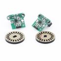
[[File:Wheel encoder rcrc.jpg|125px|thumb|left|HC-020K Wheel Encoder]] | [[File:Wheel encoder rcrc.jpg|125px|thumb|left|HC-020K Wheel Encoder]] | ||
| − | [[File:external_dac_rcrc.jpg|125px|thumb| | + | [[File:external_dac_rcrc.jpg|125px|thumb|center|External DAC]] |
Revision as of 01:41, 23 May 2021
Contents
(RC)^2
(RC)^2
Abstract
<2-3 sentence abstract>
Introduction
The project was divided into N modules:
- Sensor ...
- Motor..
- ...
- Android
Team Members & Responsibilities
<Team Picture>
Gitlab Project Link - https://gitlab.com/rc-2/sjtwo-c
- Sensor
- Huy - https://gitlab.com/vyhuy2004
- Prabjyot - https://gitlab.com/PrabjyotObhi
- Motor
- Jesse - https://gitlab.com/JessePhams
- Michael - https://gitlab.com/mwmichaelwang
- Geographical
- Brian - https://gitlab.com/Brian1234132
- Arun - https://gitlab.com/arunhiremath92
- Communication Bridge Controller & LCD
- Prabjyot - https://gitlab.com/PrabjyotObhi
- Arun - https://gitlab.com/arunhiremath92
Schedule
| Week# | Start Date | End Date | Task | Status |
|---|---|---|---|---|
| 1 | 03/01/2021 | 03/07/2021 |
|
Complete |
| 2 | 03/08/2021 | 03/14/2021 |
|
Complete |
| 3 | 03/15/2021 | 03/21/2021 |
|
Complete |
| 4 | 03/22/2021 | 03/28/2021 |
|
Complete |
| 5 | 03/29/2021 | 04/04/2021 |
|
Complete |
| 6 | 04/05/2021 | 04/11/2021 |
|
In Progress |
| 7 | 04/12/2021 | 04/18/2021 |
|
To-do |
| 8 | 04/19/2021 | 04/25/2021 |
|
To-do |
| 9 | 04/26/2021 | 05/02/2021 |
|
To-do |
| 10 | 05/03/2021 | 05/09/2021 |
|
To-do |
| 11 | 05/10/2021 | 05/16/2021 |
|
To-do |
| 12 | 05/17/2021 | 05/23/2021 |
|
To-do |
| 13 | 05/24/2021 | 05/26/2021 |
|
To-do |
Parts List & Cost
TODO: Check Drive and add to this table
| Item# | Part Desciption | Vendor | Qty | Cost |
|---|---|---|---|---|
| 1 | RC Car | Traxxas | 1 | $250.00 |
| 2 | CAN Transceivers MCP2551-I/P | Microchip [2] | 8 | Free Samples |
| 3 | GPS Module | Adafruit [3] | 1 | $59.99 |
| 4 | Compass | Adafruit [4] | 1 | $14.95 |
| 5 | ESP8266 (WiFi) | DIYmall [5] | 1 | $14.95 |
| 6 | HC-020K (Wheel Encoder) | Hilitchi [6] | 1 | $8.99 |
| 7 | URM09 Ultrasonic Sensor (I²C) | DFRobot [7] | 4 | $12.90 |
| 8 | SJ2 Board Microcontroller | SCE [8] | 5 | $250.00 |
| 9 | Male/Female Headers | DEPEPE [9] | 1 | $5.00 |
| 10 | Screw Terminal Block Connectors | DZGGI [10] | 1 | $7.99 |
| 11 | CR1220 Lithium Battery | Energizer [11] | 1 | $5.90 |
Printed Circuit Board
<Picture and information, including links to your PCB>
CAN Communication
<Talk about your message IDs or communication strategy, such as periodic transmission, MIA management etc.>
Hardware Design
<Show your CAN bus hardware design>
DBC File
VERSION ""

NS_ :
	BA_
	BA_DEF_
	BA_DEF_DEF_
	BA_DEF_DEF_REL_
	BA_DEF_REL_
	BA_DEF_SGTYPE_
	BA_REL_
	BA_SGTYPE_
	BO_TX_BU_
	BU_BO_REL_
	BU_EV_REL_
	BU_SG_REL_
	CAT_
	CAT_DEF_
	CM_
	ENVVAR_DATA_
	EV_DATA_
	FILTER
	NS_DESC_
	SGTYPE_
	SGTYPE_VAL_
	SG_MUL_VAL_
	SIGTYPE_VALTYPE_
	SIG_GROUP_
	SIG_TYPE_REF_
	SIG_VALTYPE_
	VAL_
	VAL_TABLE_

BS_:

BU_: DBG DRIVER IO MOTOR SENSOR GEO BRIDGE


BO_ 101 DRIVE_STOP: 1 BRIDGE
 SG_ DRIVE_STOP : 0|8@1+ (1,0) [0|0] "" DRIVER

BO_ 102 DRIVE_START: 1 BRIDGE
 SG_ DRIVE_START : 0|8@1+ (1,0) [0|0] "" DRIVER

BO_ 121 GPS_DESTINATION_LOCATION: 8 BRIDGE
 SG_ DEST_LATITUDE : 0|28@1+ (0.000001,-90.000000) [-90|90] "deg" GEO
 SG_ DEST_LONGITUDE : 28|29@1+ (0.000001,-180.000000) [-180|180] "deg" GEO

BO_ 131 SONAR_VALUES: 8 SENSOR
 SG_ SONAR_VALUES_left : 0|8@1+ (1,0) [0|150] "cm" DRIVER
 SG_ SONAR_VALUES_right : 8|8@1+ (1,0) [0|150] "cm" DRIVER
 SG_ SONAR_VALUES_front : 16|8@1+ (1,0) [0|150] "cm" DRIVER
 SG_ SONAR_VALUES_back : 24|8@1+ (1,0) [0|150] "cm" DRIVER

BO_ 141 COMPASS_HEADING_DISTANCE: 8 GEO
  SG_ HEADING : 0|12@1+ (0.1,0) [0|359.9] "deg" DRIVER,BRIDGE
  SG_ BEARING : 12|12@1+ (0.1,0) [0|359.9] "deg" DRIVER,BRIDGE
  SG_ DISTANCE : 24|17@1+ (0.01,0) [0|0] "m" DRIVER,BRIDGE

BO_ 151 MOTOR_VALUES: 3 DRIVER
 SG_ MOTOR_VALUES_speed : 0|8@1+ (1,-25) [-25|25] "kph" MOTOR
 SG_ MOTOR_VALUES_steering : 8|6@1+ (0.1,-2.1) [-2.1|2.1] "deg" MOTOR

BO_ 161 MOTOR_VALUES_TO_DRIVER: 3 MOTOR
 SG_ MOTOR_VALUES_TO_DRIVER_speed : 0|8@1+ (1,-25) [-25|25] "kph" DRIVER

BO_ 171 GPS_DESTINATION_REACHED: 1 GEO
 SG_ DESTINATION_REACHED : 0|1@1+ (1,0) [0|1] "bool" DRIVER,BRIDGE

BO_ 181 GPS_RAW_DATA: 8 GEO
 SG_ CURR_LATITUDE : 0|28@1+ (0.000001,-90.000000) [-90|90] "deg" BRIDGE
 SG_ CURR_LONGITUDE : 28|29@1+ (0.000001,-180.000000) [-180|180] "deg" BRIDGE
 SG_ GPS_QUALITY : 57|2@1+ (1,0) [0|2] "val" BRIDGE

BO_ 182 COMPASS_ACCEL_RAW_DATA: 6 GEO
 SG_ ACCEL_X : 0|16@1+ (0.01,-162.01) [-162.01|162.01] "ms^2" BRIDGE
 SG_ ACCEL_Y : 16|16@1+ (0.01,-162.01) [-162.01|162.01] "ms^2" BRIDGE
 SG_ ACCEL_Z : 32|16@1+ (0.01,-162.01) [-162.01|162.01] "ms^2" BRIDGE

BO_ 183 COMPASS_MAG_RAW_DATA: 6 GEO
 SG_ MAG_X : 0|16@1+ (0.01,-162.01) [-162.01|162.01] "mT" BRIDGE
 SG_ MAG_Y : 16|16@1+ (0.01,-162.01) [-162.01|162.01] "mT" BRIDGE
 SG_ MAG_Z : 32|16@1+ (0.01,-162.01) [-162.01|162.01] "mT" BRIDGE

BO_ 191 DRIVER_HEARTBEAT: 1 DRIVER
 SG_ DRIVER_HEARTBEAT_cmd : 0|8@1+ (1,0) [0|0] "" SENSOR, MOTOR, GEO

CM_ BU_ DRIVER "The driver controller driving the car";
CM_ BU_ MOTOR "The motor controller of the car";
CM_ BU_ SENSOR "The sensor controller of the car";
CM_ BO_ 191 "Sync message used to synchronize the controllers";
CM_ SG_ 191 DRIVER_HEARTBEAT_cmd "Heartbeat command from the driver";

BA_DEF_ "BusType" STRING ;
BA_DEF_ BO_ "GenMsgCycleTime" INT 0 0;
BA_DEF_ SG_ "FieldType" STRING ;

BA_DEF_DEF_ "BusType" "CAN";
BA_DEF_DEF_ "FieldType" "";
BA_DEF_DEF_ "GenMsgCycleTime" 0;

BA_ "GenMsgCycleTime" BO_ 100 1000;
BA_ "GenMsgCycleTime" BO_ 200 50;
BA_ "FieldType" SG_ 100 DRIVER_HEARTBEAT_cmd "DRIVER_HEARTBEAT_cmd";

VAL_ 100 DRIVER_HEARTBEAT_cmd 2 "DRIVER_HEARTBEAT_cmd_REBOOT" 1 "DRIVER_HEARTBEAT_cmd_SYNC" 0 "DRIVER_HEARTBEAT_cmd_NOOP" ;
Sensor ECU
<Picture and link to Gitlab>
Hardware Design
Software Design
<List the code modules that are being called periodically.>
Technical Challenges
< List of problems and their detailed resolutions>
Motor ECU
<Picture and link to Gitlab>
Hardware Design
The hardware design for the motor node requires four main components to be connected to the SJ2 Board:
1. CAN Transceiver
- This module will be used to communicate with the Driver Node to receive the desired speed and steering angle through CAN communication protocol. This module will also be used to transmit the car's current speed to the Driver Node. The CAN transceiver will be powered by a +3.3V source with its Transmit Line (Tx) connected to GPIO Pin P0.1 and its Receive Line (Rx) connected to GPIO Pin P0.0.
2. RC Transmit Controller
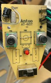
- Due to the Electronic Speed Controller (ESC) being completely resined into the RC Car's base, there was no direct method of controlling the provided ESC with the SJ2 Board. The team decided to control the ESC using the transmit controller by measuring the internal potentiometer's voltage signal line to the transmit circuit and replicating those voltage values with a Digital-to-Analog Converter (DAC). This transmit controller takes in two input lines to its ports:
- CON2 PORT
- This port takes in one input, which controls the steering angle of the car. The voltage value for the steering to be straight was measured at +2.0V. Lower voltage values steer the car left and higher voltage values steer the car right. The voltage input to this port comes from the External DAC.
- CON3 PORT
- This port takes in one input, which controls the speed of the car. The voltage value for the car to be stationary was measured at approximately +1.5V. Lower voltage values accelerated the car forward and higher voltage values accelerated the car backwards. The voltage input to this port comes from the SJ2 Board's DAC pin P0.26.
3. External DAC
- Since the SJ2 Board has only one DAC pin, which is used to control the motor speed, an additional external DAC is needed to control the car's servo motor for steering.
4. Wheel Encoder
- This module is used by the motor node to measure the car's speed by keeping track of how many revolutions the rotary revolves around the sensor. The rotary contains twenty hole slits, so a full revolution will "tick" the sensor twenty times.
Software Design
The motor node is designed to receive a desired speed and a desired steering angle from the driver node. These values will be used to adjust the RC Car's motor speed and servo motor angle to align with those requested values.
There are four public functions that are provided in the motor node.
1. void motors__init(void)
- This function is used by the periodic callback to initialize the required peripherals used to control the motor speed as well as the servo motor angle.
2. void motors__run(void)
- This function is used by the periodic callback to set the motor speed and the servo motor angle. This public function will invoke two private functions, motors__speed_handler() which handles the motor speed of the car, and motors__steering_handler() which handles the steering angle of the car.
- motors__speed_handler()
- This private function controls the RC Car's speed, which is calculated by measuring the circumference of the car's wheel and finding out how many times it rotates within a given time frame. Setting the time frame and obtaining the circumference of the wheel is trivial, however, obtaining the amount of rotations required additional effort. We used an HC-020K Wheel Encoder to measure how many times the wheel rotated around its axle and connected the +5V output to one of the SJ2's GPIO pins. This pin was then attached to an interrupt service, which incremented the static variable holding the number of times the wheel has rotated. The sample code to calculate the speed of the car is shown below.
  static int8_t motors__private_get_speed_kmh(void) {
    int8_t motor_speed = current_speed_kmh;
    uint64_t current_time_ms = sys_time__get_uptime_ms();
    uint64_t time_elapsed_ms = current_time_ms - wheel_encoder_previous_time_ms;

    if (time_elapsed_ms >= 100U) {
      wheel_encoder_previous_time_ms = current_time_ms;

      if (time_elapsed_ms > 0) {
        float number_of_wheel_cycles = (float)wheel_encoder_number_of_ticks / (float)WHEEL_ENCODER_TICKS_PER_CYCLE;
        float distance_travelled_cm = (float)(number_of_wheel_cycles * WHEEL_CIRCUMFERENCE_CM);

        motor_speed =
            (distance_travelled_cm / CENTIMETERS_IN_ONE_KILOMETER) / ((float)time_elapsed_ms / MILLISECONDS_IN_ONE_HOUR);

        wheel_encoder_number_of_ticks = 0U;

        if (MOTORS__DIRECTION_REVERSE == current_motor_direction) {
          motor_speed *= -1;
        }

      }
    }

    return motor_speed;
}- motors__steering_handler()
- This private function controls the RC Car's steering angle.
3. void motors__set_speed_and_steering_values(dbc_MOTOR_VALUES_s *motor_values)
- This function is used by the CAN Bus Message Handler to set the desired speed and steering angle. When the CAN Bus Message Handler module receives a CAN package, it will decode the motor values and call this function. This function is also used by the MIA handler as well to stop the RC Car if it doesn't receive any CAN messages from the driver node ten times in a 10Hz periodic callback.
4. dbc_MOTOR_VALUES_TO_DRIVER_s motors__get_motor_values(void)
- This function is used by the CAN Bus Message Handler to transmit the current speed of the car.
Technical Challenges
< List of problems and their detailed resolutions>
Geographical Controller
<Picture and link to Gitlab>
Hardware Design
Software Design
<List the code modules that are being called periodically.>
Technical Challenges
< List of problems and their detailed resolutions>
Communication Bridge Controller & LCD
<Picture and link to Gitlab>
Hardware Design
Software Design
<List the code modules that are being called periodically.>
Technical Challenges
< List of problems and their detailed resolutions>
Master Module
<Picture and link to Gitlab>
Hardware Design
Software Design
<List the code modules that are being called periodically.>
Technical Challenges
< List of problems and their detailed resolutions>
Mobile Application
<Picture and link to Gitlab>
Hardware Design
Software Design
<List the code modules that are being called periodically.>
Technical Challenges
< List of problems and their detailed resolutions>
Conclusion
<Organized summary of the project>
<What did you learn?>
Project Video
Project Source Code
Advise for Future Students
<Bullet points and discussion>
Acknowledgement
=== References ===


