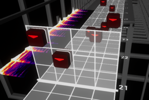
Difference between revisions of "F20: Jubeat"
Proj user9 (talk | contribs) (→Enclosure Design) |
Proj user9 (talk | contribs) (→LED matrix Driver) |
||
| (11 intermediate revisions by the same user not shown) | |||
| Line 23: | Line 23: | ||
[https://www.youtube.com/watch?v=nj6_2ywDC9Y&feature=youtu.be&ab_channel=TylerTran Gameplay Video (Youtube)] | [https://www.youtube.com/watch?v=nj6_2ywDC9Y&feature=youtu.be&ab_channel=TylerTran Gameplay Video (Youtube)] | ||
| + | |||
| + | == Abstract == | ||
| + | |||
| + | In this project we remastered the arcade music game Jubeat in a tight budget. We used a 64x64 LED matrix to display the animation, 12 capsense buttons to detect the finger touch inputs, and an mp3 module connected to the speakers to play the songs. Drivers for the LED matrix display, the capsense, and the mp3 module were developed for this project. | ||
| + | |||
| + | |||
| + | For the game design, the timing and the animation that will be lit on which grids were configured and stored into a SD card that would be read throughout the game. Each of the 12 animations in the game play mode had its own FreeRTOS task for the game. High scores for each song were also saved in an SD card. There is a start and end screen, a song selection menu and game play screen that transition with the game state throughout the game. | ||
| + | |||
| + | |||
| + | An enclosure was also designed and developed to enhance the gaming experience. It was constructed using a 3D printer. | ||
| + | |||
| + | |||
| + | This game was successfully developed with an enclosure, colorful graphics and animation. | ||
== Introduction == | == Introduction == | ||
| − | Jubeat is a music game uses an arrangement of a 3x4 grid for the game play. An animation pops up on each grid according to the beat of the song. The player has to use his fingers to tap on the screen and catch the animation in time. The scoreboard locates on the top row of the LED display. Different scores will be given depending on when the player catch the animation. Tapes can be judged as PERFECT, OK, | + | Jubeat is a music game uses an arrangement of a 3x4 grid for the game play. An animation pops up on each grid according to the beat of the song. The player has to use his fingers to tap on the screen and catch the animation in time. The scoreboard locates on the top row of the LED display. Different scores will be given depending on when the player catch the animation. Tapes can be judged as PERFECT, OK, or MISS. |
== Objectives & Introduction == | == Objectives & Introduction == | ||
| Line 39: | Line 52: | ||
| − | Team objectives | + | === Team objectives === |
1. Understand how each sensor/module works by studying the datasheets to develop an actual product. | 1. Understand how each sensor/module works by studying the datasheets to develop an actual product. | ||
| Line 333: | Line 346: | ||
{| | {| | ||
| − | |[[File:Jubeat | + | |[[File:Jubeat schematic 1.JPG|thumb|left|800px|Product Schematic]] |
| + | |||
| + | |} | ||
| Line 340: | Line 355: | ||
Note that you have to leave some space between the films to avoid them touching each other and getting the wrong input signal of the buttons during the game play. | Note that you have to leave some space between the films to avoid them touching each other and getting the wrong input signal of the buttons during the game play. | ||
| − | [[File:Button wiring.jpg|left|thumb|350px|Capsense buttons wiring under the hood]] | + | {| |
| + | |[[File:Button wiring.jpg|left|thumb|350px|Capsense buttons wiring under the hood]] | ||
|} | |} | ||
| Line 353: | Line 369: | ||
===LED matrix Driver=== | ===LED matrix Driver=== | ||
| − | Since, it is very inefficient to light up all the 4096 leds at the same time, The images/frames are shown on the display through a process called scanning where only a few rows expressed by its scan rate are driven at the same time. For the scan rate of 1:32 in a 64x64 led matrix, each row from the top half and the bottom half are displayed serially. | + | Since, it is very inefficient to light up all the 4096 leds at the same time, The images/frames are shown on the display through a process called scanning where only a few rows expressed by its scan rate are driven at the same time. For the scan rate of 1:32 in a 64x64 led matrix, each row from the top half and the bottom half are displayed serially, more details can be found in the article from sparkfun in the reference section below. |
For each row of pixels, we repeat the following cycle of steps: | For each row of pixels, we repeat the following cycle of steps: | ||
| Line 621: | Line 637: | ||
*[https://www.sparkfun.com/datasheets/Components/MPR121.pdf Capacitive touch MPR121 datasheet] | *[https://www.sparkfun.com/datasheets/Components/MPR121.pdf Capacitive touch MPR121 datasheet] | ||
| + | |||
| + | *[https://www.sparkfun.com/news/2650 LED matrix background] | ||
Latest revision as of 06:01, 22 December 2020
Contents
- 1 Game photos
- 2 Abstract
- 3 Introduction
- 4 Objectives & Introduction
- 5 Schedule
- 6 Parts List & Cost
- 7 Enclosure Design
- 8 Hardware Design
- 9 Schematic & wiring
- 10 Hardware Interface
- 11 Game Software Design
- 12 Song Format/Song Design
- 13 Testing & Technical Challenges
- 14 Conclusion
- 15 References
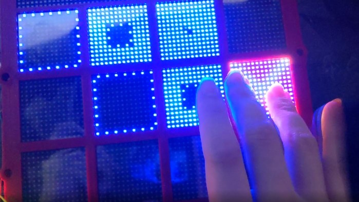
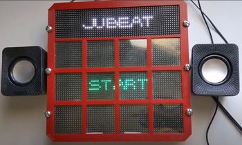
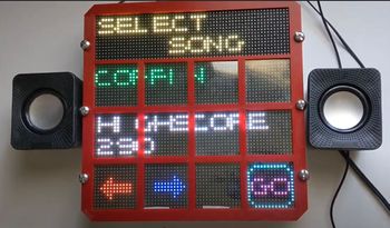
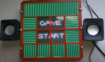
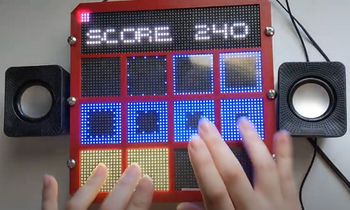
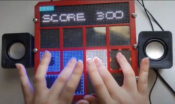
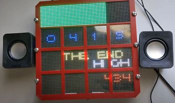
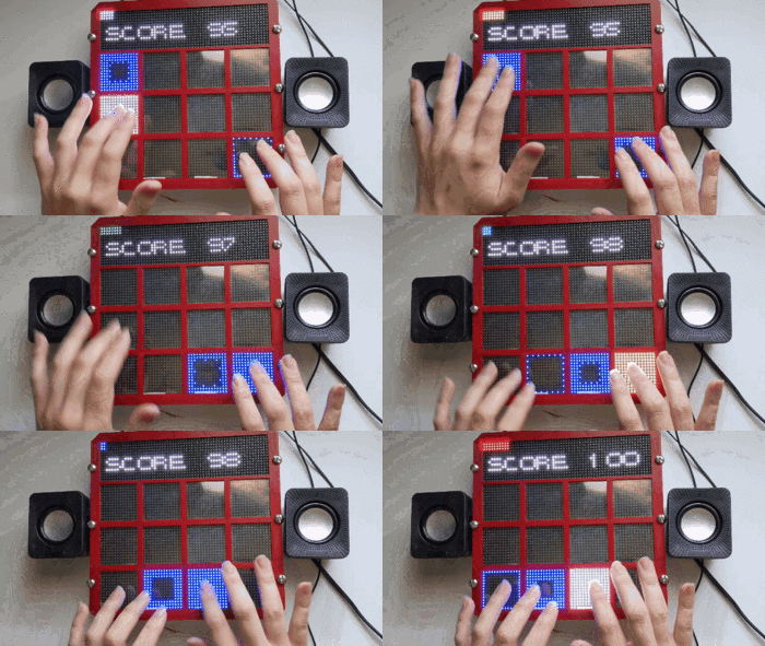
Game photos
Gameplay Video (Youtube)
Abstract
In this project we remastered the arcade music game Jubeat in a tight budget. We used a 64x64 LED matrix to display the animation, 12 capsense buttons to detect the finger touch inputs, and an mp3 module connected to the speakers to play the songs. Drivers for the LED matrix display, the capsense, and the mp3 module were developed for this project.
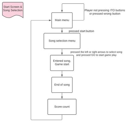
For the game design, the timing and the animation that will be lit on which grids were configured and stored into a SD card that would be read throughout the game. Each of the 12 animations in the game play mode had its own FreeRTOS task for the game. High scores for each song were also saved in an SD card. There is a start and end screen, a song selection menu and game play screen that transition with the game state throughout the game.
An enclosure was also designed and developed to enhance the gaming experience. It was constructed using a 3D printer.
This game was successfully developed with an enclosure, colorful graphics and animation.
Introduction
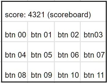
Jubeat is a music game uses an arrangement of a 3x4 grid for the game play. An animation pops up on each grid according to the beat of the song. The player has to use his fingers to tap on the screen and catch the animation in time. The scoreboard locates on the top row of the LED display. Different scores will be given depending on when the player catch the animation. Tapes can be judged as PERFECT, OK, or MISS.
Objectives & Introduction
This system:
1. Recognizes finger touch as the input to record the score.
2. Supports real time capacitive touch detection on a LED matrix display.
3. Update corresponding score on the LED display.
4. Outputs the audio via a mp3 module and the soundtracks are stored in an SD card.
Team objectives
1. Understand how each sensor/module works by studying the datasheets to develop an actual product.
2. Understand the proper use of freeRTOS semaphores and event groups in order to send/receive the data between multiple tasks.
3. Integrate modules and develop smooth game logic. Identify each game state and its transition to next state.
4. Learn how to cooperate codes and logic written by team members through git and branch control.
Team Members & Responsibilities
- Ka In Ng
- Git Admin
- Audio Driver
- Capsense Driver
- Menu Design
- Animation Design
- Hardware wiring and assembly (Each of us built our own copy)
- Tyler Tran
- Enclosure Design
- Gameplay Development
- Animation Design
- Game Debug
- Hardware wiring and assembly (Each of us built our own copy)
- Srikar Narapureddy
- LED Matrix Driver
- Capsense Driver
- Gameplay Development
- Menu Design
- Animation Design
- Hardware wiring and assembly (Each of us built our own copy)
Schedule
| Week# | Date | Task | Status |
|---|---|---|---|
| 0 | 10/13/2020 |
|
|
| 1 | 10/21/2020 |
|
|
| 2 | 10/28/2020 |
|
|
| 3 | 11/4/2020 |
|
|
| 4 | 11/11/2020 |
|
|
| 5 | 11/18/2020 |
|
|
| 6 | 11/24/2020 |
|
|
| 7 | 12/1/2020 |
|
|
| 8 | 12/8/2020 |
|
|
Parts List & Cost
| Part Name | Part Model & link | Quantity | Cost Per Unit |
|---|---|---|---|
| Evaluation Board | SJ2 board (NXP LPC4078 MCU) | 1 | $50 |
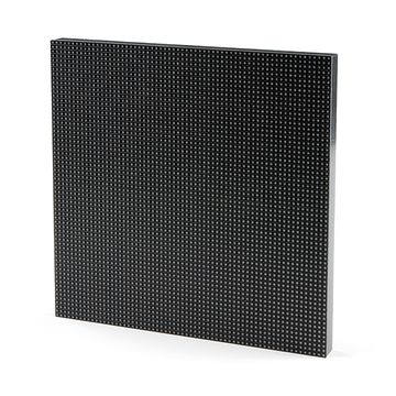
| 64x64 RGB LED Matrix | 3mm Pitch - 192mm x 192mm | 1 | $59.95 |
| 5V Power Supply | Aclorol 5V 5A 25W AC-DC | 1 | $13.19 |
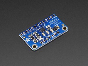
| 12-Key Capacitive Touch Sensor | Adafruit MPR121 | 1 | $7.95 |
| ITO (Indium Tin Oxide) Coated PET Plastic | 100mm x 200mm | 2 | $9.95 |
| DFPlayer Mini | MakerHawk DFPlayer Mini | 2 | $3.99 |
| Speaker | 3" Diameter - 4 Ohm 3 Watt OR ANY BETTER CHOICE | 2 | $1.95 |
Enclosure Design
The enclosure is made to divide the The enclosure is made with 4 goals in mind.
- Divide the LED display into a display area and 4x3 grid
- Route wires cleanly
- Hold ITO plastic squares in place
- House hardware
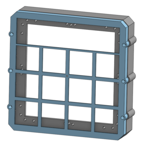
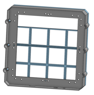
After taking measurements, the first goal is easily met by drawing out a simple grid that conforms to the size of the LED matrix. Clean wire routing is done by creating grooves in the sides and on the grid of the enclosure, where 30-gauge wire is glued in place. Extrusions are placed all around the top part of the enclosure, at the same thickness of the ITO squares, allowing for a friction fit. Lastly, the base of the enclosure contains a large open area to contain all hardware. Printing the enclosure requires a 3D printer with a minimum size of 220 mm x 210 mm.
The enclosure represented a large portion of the issues faced during design, namely the connections from the wire to the ITO. The initial aim was to friction fit the wires against the ITO. While this was successful most of the time, 100% reliability is a necessity. Some less-reliable connections are supplemented by copious amounts of superglue and some tape.
Hardware Design
Implementation
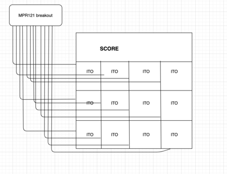
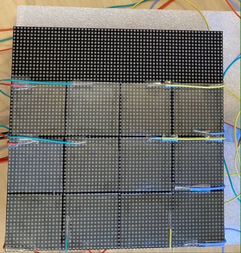
The 64x64 matrix display is divided into 4 rows, the top row (16x64) is used as a scoreboard, and the remaining rows are divided into 12 square regions, each 16x16 that connects to the ITO buttons that connects to the capacitive sensor for the game input.
LED Matrix
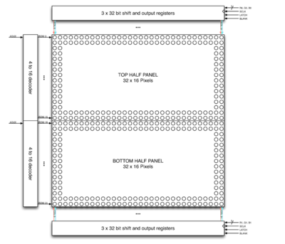
A 64x64 RGB led matrix display is used in this project, The display has a scan rate of 1:32 and uses six 64-bit shift registers.
- The register shift inputs R1,G1,B1 and R2,G2,B2 are used to store the Red ,Green and Blue states for the two rows .i.e 128 LEDs from the top and bottom halves of the display.
- The rows are multiplexed using the 5 row pins A,B,C,D,E.
- The scanning is controlled by Output enable(OE) and Latch(LAT) pins.
- OE is used to disable the leds when changing the row during scanning.
- LAT is used to latch in the row data after the shifting is complete.
In total, 14 GPIO pins are used to drive the display, see the next section for more details about driving the display.
Technical details
1. Brightness: 2800cd/square meter.
2. Size: 192mm x 192mm.
3. Pitch: 3M.
4. 5 Addressable Pins.
5. Scan: 1/32.
6. Refresh Frequency: >=400HZ.
7. Weight: 235g.
Power: The led matrix needs an external power supply capable of supplying at least 8A current at 5V.
Capacitive touch breakout
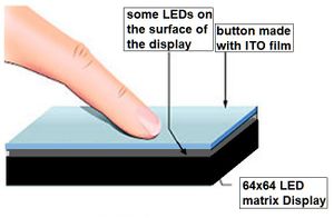
The capacitive touch sensor input pins are wired to 12 pieces of transparent ITO films which are placed on top of each section of the LED matrix display. When the game starts, the song stored in the SD card of the mp3 module starts to play. Animation shows up on any of the 12 LED sections and the player has to catch the animation on time to receive scores. The breakout board consists of the IC MPR121 which uses I2C to communicate with the SJ-2 board. It supports four I2C addresses and each address can be used to detect 12 individual touches.
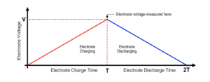
The MPR121 uses a constant DC charge current scheme for capacitance measurement. Each channel is measured serially and is charged and discharged completely to ground to measure the capacitance. Other channels are grounded during the measurement.
mp3 module
Schematic & wiring
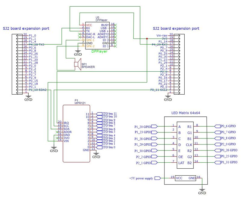
The following schematic shows the wiring of all components.
To make the 12 capcitive touch buttons work, the ITO film is cut into the approximate size of a 15x15 LED matrix. The gameplay animation of each grid is a 14x14 matrix so a 15x15 matrix size is a good fit for the buttons since the enclosure can hide the edges. The films are glued separately onto the 64x64 LED matrix display.
Note that you have to leave some space between the films to avoid them touching each other and getting the wrong input signal of the buttons during the game play.
Hardware Interface
We have used three external sensors/modules in this project to interact with the SJ2 board.
- The 64x64 LED matrix display is used to display the game animation and graphic.
- The mp3 module is used to play the songs during game play.
- The capactive touch sensor is used to receive button press inputs to control the game.
The rest of the section shows the driver of each sensor/module and will briefly go through the logic and usage of each.
LED matrix Driver
Since, it is very inefficient to light up all the 4096 leds at the same time, The images/frames are shown on the display through a process called scanning where only a few rows expressed by its scan rate are driven at the same time. For the scan rate of 1:32 in a 64x64 led matrix, each row from the top half and the bottom half are displayed serially, more details can be found in the article from sparkfun in the reference section below.
For each row of pixels, we repeat the following cycle of steps:
- Clock in the data for the current row one bit at a time
- Pull the latch and output enable pins high. This enables the latch, allowing the row data to reach the output driver but it also disables the output so that no LEDs are lit while we're switching rows.
- Switch rows by driving the appropriate row select lines.
- Pull the latch and output enable pins low again, enabling the output and closing the latch so we can clock in the next row of data.
The pixel data is put in a global buffer in RAM, this buffer is periodically accessed by the display task to refresh the display.
Code Snippet:
while (1) {
    for (int row = 0; row < 32; row++) {
      // left half
      for (int x = 31; x >= 0; x--) {
        logic = ((led_matrix[0][row][0] >> x) & 1);
        gpio__set_logic(R1, logic);
        logic = ((led_matrix[1][row][0] >> x) & 1);
        gpio__set_logic(G1, logic);
        logic = ((led_matrix[2][row][0] >> x) & 1);
        gpio__set_logic(B1, logic);
        logic = ((led_matrix[0][row + 32][0] >> x) & 1);
        gpio__set_logic(R2, logic);
        logic = ((led_matrix[1][row + 32][0] >> x) & 1);
        gpio__set_logic(G2, logic);
        logic = ((led_matrix[2][row + 32][0] >> x) & 1);
        gpio__set_logic(B2, logic);
        gpio__set(CLK);
        gpio__reset(CLK);
      }
      // right half
      for (int x = 31; x >= 0; x--) {
        logic = ((led_matrix[0][row][1] >> x) & 1);
        gpio__set_logic(R1, logic);
        logic = ((led_matrix[1][row][1] >> x) & 1);
        gpio__set_logic(G1, logic);
        logic = ((led_matrix[2][row][1] >> x) & 1);
        gpio__set_logic(B1, logic);
        logic = ((led_matrix[0][row + 32][1] >> x) & 1);
        gpio__set_logic(R2, logic);
        logic = ((led_matrix[1][row + 32][1] >> x) & 1);
        gpio__set_logic(G2, logic);
        logic = ((led_matrix[2][row + 32][1] >> x) & 1);
        gpio__set_logic(B2, logic);
        gpio__set(CLK);
        gpio__reset(CLK);
      }
      gpio__set(OE);
      gpio__set(LAT);
      gpio__set_logic(A, (row & (1 << 0)) >> 0);
      gpio__set_logic(B, (row & (1 << 1)) >> 1);
      gpio__set_logic(C, (row & (1 << 2)) >> 2);
      gpio__set_logic(D, (row & (1 << 3)) >> 3);
      gpio__set_logic(E, (row & (1 << 4)) >> 4);
      gpio__reset(LAT);
      gpio__reset(OE);
    }
    vTaskDelayUntil(&xLastWakeTime, xFrequency);
  }
}
Audio Driver
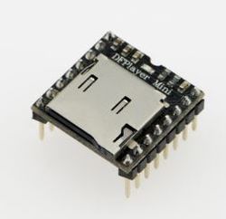
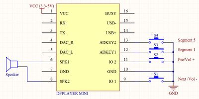
The audio driver is used to play the sound tracks that stored on a SD card of the DFPlayer mp3 module.
1. The DFPlayer mp3 module is connected to the SJ2 board via I2C. Each command takes 10 UART data transmissions.
2. When the board is turned on, the function audio_init will be called and get ready.
3. The audio_specify_track function is called after the player choose which track to play using the capacitive touch game buttons.
4. The songs have to be stored in this format in the SD card:
- Create a folder named "01" in the root directory to store the songs
- Name the songs in the form of 001.mp3, 002.mp3 etc. up to 256 songs
- Select the song by its name and pass it to the param2 of the audio command
5. Then the audio_start_play function is being called right after to start the song playback.
6. Each audio command contains a 2 byte checksum to maintain the data integrity.
Code Snippet:
void send_audio_command(uart_e uart, uint8_t audio_command, uint8_t param1, uint8_t param2) {
  uint16_t checksum_2byte = audio_calculate_2byte_checksum(audio_command, param1, param2);
  uint8_t checksum_lowbyte = checksum_2byte;
  uint8_t checksum_highbyte = (checksum_2byte >> 8);

  uint8_t audio_full_command[10] = {start_byte, version_byte, command_length,    audio_command,    feedback,
                                    param1,     param2,       checksum_highbyte, checksum_lowbyte, end_byte};
  for (int i = 0; i < 10; i++) {
    uart__polled_put(uart, audio_full_command[i]);
  }
}
Capacitive touch logic
The capacitive touch sensor is used to identify the finger touch on the ITO button which is transparent and conductive. An input signal from a finger touch is sent and the sensor outputs an interrupt signal to the SJ2 board.
1. Each capacitive touch sensor input pin is connected to a ITO film that acts as the game buttons. There are 12 of them throughout the game.
2. When any of the 12 button is being pressed, an interrupt is triggered and we find out the pin that caused the interrupt.
Code Snippet:
int8_t get_touching_pin(void) {
  uint8_t i;        // i = touching pin number, pin released when i = -1;
  currently_touch = (i2c__read_single(I2C__2, 0xB4, 0x01) << 8); // the MSB 4 input pins (pin 11 - 8)
  currently_touch += i2c__read_single(I2C__2, 0xB4, 0x00);       // add the LSB 8 input pins (pin 7 - 0)
  currently_touch &= 0x0FFF;                                     // remove 4 MSB for slave register 0x01

  for (i = 0; i < 12; i++) {
    if ((currently_touch & (1 << i))) {
      fprintf(stderr, "touching pin %d \n", i);
      return i;
    }
  }
  return -1;
}
Game Software Design
The game’s software design consists of:
- Main game loop task
- Equalizer display task
- Score display task
- Capsense touch task
- 12 FreeRTOS tasks for each square in the 4x3 grid.
Main Game Loop Task
The responsibilities of the main game loop are to handle all menus, the state of the game and loading in the gameplay events (timing and position of the gameplay touch events).
Start Screen
Simply uses a semaphore triggered by any button to move to the next state
Song Selection
Utilizes an event group to distinguish between button presses. Actions vary depending on which button is pressed.
- Increment/Decrement Song Selection
- Start Song
Gameplay
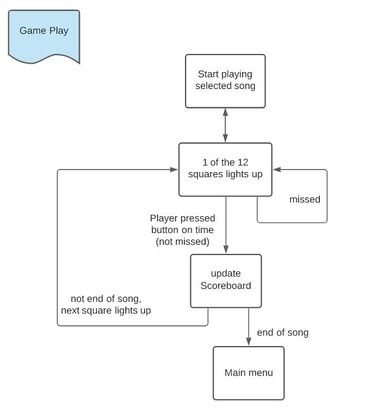
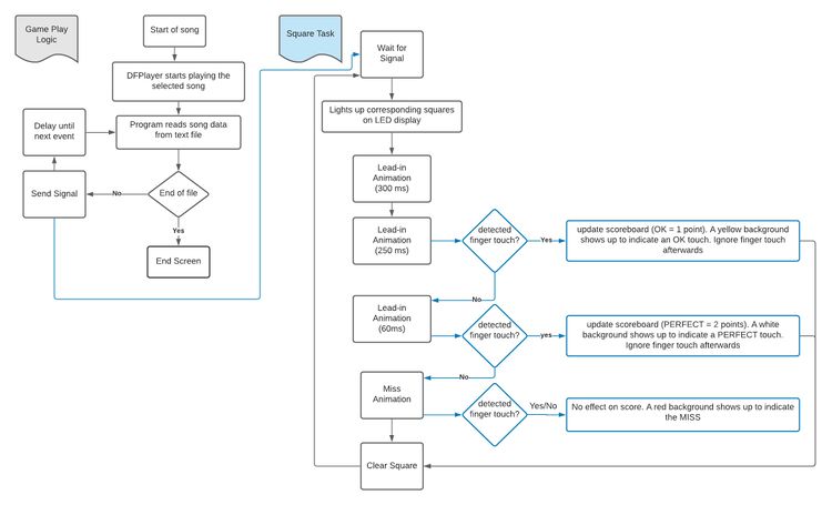
Once gameplay has begun, the task sends signals the spectrogram to start and loads in song events from a specified text file, as shown in the following diagram: [Gameplay state diagram]
End Screen
Score is displayed at the end with a count-up animation. High score is also displayed in different colors depending on the final scores compared to the high score. High score is written to a file if a higher one is met. Tapping any square will return to the start screen.
Equalizer Display Task
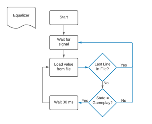
The equalizer displays only a single range of frequencies, roughly 0-350Hz, representing the bass. The values displayed are not evaluated in real time, rather, using a python script, the values are sampled from the audio file at a 30ms interval and are saved to a file and placed on the SD card. The file is then read by the SJ2 board at a 30ms interval to display an equalizer at the top of the game while playing.
Score Display Task
The score display task simply updates the score at the top of the screen during gameplay.
Capsense Touch Task
This task handles determining which capsense input is detected, and sends semaphore signals or event group signals based on the current game state.
State = Start Screen
- Sends a semaphore
State = Song Selection
- Sets bits on event group based on which squares are pressed
State = Gameplay
- Compares timing of press to gameplay events currently being played
- Sends semaphore signal or not depending on previous evaluation
- Based on timing, will judge press as perfect or not and update scores.
State = End Screen
- Sends a semaphore
State = Other (Mid-transition animations)
- Does nothing
12 Square Tasks
Each of the 12 squares in the 4x3 grid uses its own FreeRTOS task to easily handle multiple animations simultaneously. Upon receiving a signal from the main game loop task, the task will perform its animation utilizing another semaphore. This second semaphore will be sent by the Capsense Touch Task to interrupt the animation and display a judgement (Perfect/OK). If the animation is not interrupted, this is a miss.
|
Song Format/Song Design
This section covers the format and method to adding a new song to the game. The songs in this project require 4 parts.
- A song file in the correct format on the SJ2 board's SD card
- A equalizer file in the correct format on the SJ2 board's SD card (optional)
- An entry in a "list" file on the SJ2 board's SD card
- A corresponding audio file on the mp3 player's SD card
By meeting these requirements, new songs may be added to the game without any changes to the code.
Song file format/creation
The song file consists of lines of numbers in the following format:
- TTTTTTTBB
- T represents a digit of the timing of the event
- B represents a digit of the square (0-11)
For example an entry of 000150702 represents square 2 at 1507 ms.
The songs are individually designed using software that Tyler Tran is the developer of. This software is for a rhythm game called "Beat Saber" which also utilizes a 4x3 grid. Using a script, the output of this software is converted to the above format. A Node.js script is used, as the initial file is a JSON formatted file and Node.js has great compatibility with the format.
Equalizer file format/creation
The songs in a .wav format can be run through a Python script to generate a equalizer file.
"list" file
The "list" file on the SD card consists of specified files in order for the game to read. The order is:
1. name of the song
2. filename of the song file
3. filename of the equalizer file
additional songs can be added by appending the proper information to this file.
Audio File
The DFPlayer Mini accepts both .mp3 files and .wav files. .wav files are preferred over .mp3 files for the sake of speed, as .mp3 files are known to take longer to decode when compared to .wav files. Whether or not this has any impact on this project was not tested.
Testing & Technical Challenges
Wiring
While this isn't a software bug, it's a physical one with software implications. The connections from the wire to the ITO coated plastic are somewhat inconsistent, resulting in both misfires and missed inputs. This hardware bug would have been easily resolved with conductive adhesive, and if given the opportunity, we would use that instead of friction fitting. However, these issues became highly present too late into development to consider the use of conductive adhesive, so steps were taken to resolve the issue in software.
The capsense peripheral has the ability to automatically adjust and tune itself to whatever is connected to its input pins. This causes a major issue in the case of inconsistent wiring as an accidental touch to an exposed wire, or a poor connection can potentially render an input square near unusable. These issues from automatic calibration additionally may not happen immediately, or it may take some time to cause major issues. We noticed that some inputs would cease functioning after playing multiple songs in a row, but would be fine after simply resetting the SJ2 board. Our resolution is to reset the capsense peripheral after the end of every song as a preventative measure against poor automatic calibration.
Failed input detection during gameplay
One of the main bugs faced during development was certain events during gameplay would consistently be met with a "miss" judgement, meaning no input was detected. This was due to a wide variety of problems, such as improperly ordered code and failing to properly manage the main game loop task. While the first problem is fairly common, the second was a major issue that went unchecked for the majority of the project and resulted in the last events of a song being unable to be detected.
In detail, the second issue (failing to properly manage the main game loop task) is that the state is switched 5 seconds after the last event is played. Initially this was done with a vTaskDelay. However, the game relies on the main game loop task updating a running timer to evaluate scores, which no longer occurs if the task is put to sleep for 5 seconds. The end result of this bug is that no event in the last few seconds of the song can be input for score. So, if this were to be done again, I'd recommend either more careful observation of the code, or moving things like a running timer to their own task. Instead, the "band-aid" fix was to replace the 5 seconds of sleep with a loop that continued updating the running timer for 5 seconds.
Future Improvement
With limited time to develop this game, here are some areas we would like to enhance for the game,
- add some sound effects to the finger touch on song selection
- plays background music while the game is idle on the start/end or song selection screens
Conclusion
We were able to successfully design and implement a capacitive touch based rhythm game using FreeRTOS. Much effort was put into making the game as realistic and in-tune as possible and this involved a lot of debugging and careful tuning of the timing, many iterations of animations with different implementations were tested. Most importantly, through the project we gained the experience involved in embedded programming and RTOS. The knowledge gained from practical usage of techniques and concepts learned from this course was fantastic, especially the chance to work at a much larger scale with many more implications than other coursework. Fortunately for us, but unfortunately for this section, because of a solid foundation, previous knowledge, and strong planning, the group only faced minor challenges in software, leaving us with not many mistakes to learn from. However, the hardware was a significant challenge, leaving us wishing we would have considered that the initial plan for the enclosure might not be completely functional, because it was not. As for lessons learned, a strong takeaway would be to consider all aspects of design and to make a "plan B" even for aspects that are assumed to be executed perfectly.
Project Video
Project Source Code
References
Acknowledgement
Much of the knowledge involved in implementing this project was learned from the Embedded Software(244) class taken by Preetpal Kang.
