Difference between revisions of "F20: Hungry Snake"
Proj user6 (talk | contribs) (→Sprite Creation) |
Proj user6 (talk | contribs) (→Game Design) |
||
| (92 intermediate revisions by the same user not shown) | |||
| Line 1: | Line 1: | ||
| + | [[File:fall2020_group6_snake_game.PNG|450px|caption|right|Hungry Snake]] | ||
| + | <!-- | ||
== Hungry Snake == | == Hungry Snake == | ||
| + | {| | ||
| + | |[[File:fall2020_group6_snake_game.PNG|600px|thumb|left|Hungry Snake]] | ||
| + | |} | ||
| + | --> | ||
== Abstract == | == Abstract == | ||
| Line 7: | Line 13: | ||
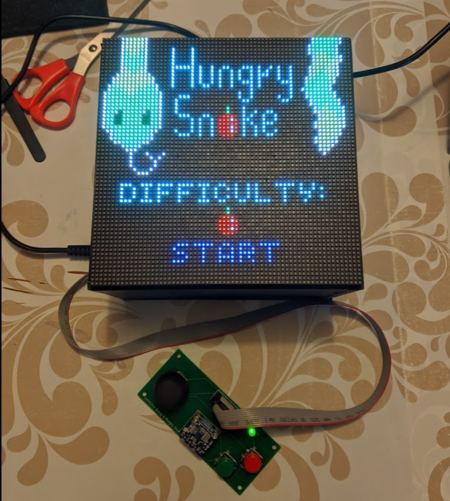
The game is composed of an 3D-printed enclosure, with two boards - one master SJ2 board tasked with gameplay and display, and another SJ2 board tasked with mp3 music play. The game display utilizes a 64 x 64 LED matrix, and player controls the snake via a controller with joystick, button, and accelerometer sensor input. | The game is composed of an 3D-printed enclosure, with two boards - one master SJ2 board tasked with gameplay and display, and another SJ2 board tasked with mp3 music play. The game display utilizes a 64 x 64 LED matrix, and player controls the snake via a controller with joystick, button, and accelerometer sensor input. | ||
| − | ==Basic Gameplay== | + | == Basic Gameplay == |
| − | The player plays a snake that is constantly moving in a direction and its body will move in a trailing fashion. | + | The player plays a snake that is constantly moving in a direction and its body will move in a trailing fashion. The goal of the game is survive as long as possible. You will attain points over time and additional points if you "eat" a fruit or enemy. As you eat more objects, the snake's body will extend so that it will become more difficult over time. A new fruit will be randomly generated in the map as you consume them. |
| − | + | There are moving obstacles as well for the player snake to avoid. If the player collides with any obstacle, they instantly die. | |
| − | + | Enemy snakes with alternating red and yellow colors spawn in the map at higher difficulty. A battle is triggered when the player snake runs into an enemy snake. When the battle starts, a progress bar appears at the bottom of the screen. The player needs to shake the controller up and down as fast as possible to "battle" the enemy snake, which will fill the progress bar. If there is no shaking, the progress bar will be continually drained. If the progress bar is drained, the player loses. If the progress bar is filled by shaking the controller, the player successfully overcame the snake and the game returns back to normal gameplay. The enemy snake you defeated will be removed and a new one will be spawned at a new location. | |
| − | + | === Scoring === | |
| − | + | * Your score increases by your score multiplier per tick of the game. Initially, this value will be 1. | |
| + | * Your score increases by 100 for eating a fruit. Additionally, your multiplier will increase by 1. | ||
| + | * Your score increases by 1000 for defeating an enemy snake. Additionally, your multiplier will increase by 1. | ||
| − | + | === Game Over Condition === | |
| − | + | * You collide with an obstacle | |
| + | * You lose a battle with an enemy snake | ||
| + | * You collide with a part of your own body | ||
| − | == | + | === Bonus Stage === |
| − | |||
| − | + | We have created a bonus stage to demonstrate our map creation framework. The game resembles frogger where you have to avoid moving cars. In this game mode, you only earn points (100) for eating fruits. Continuous score accumulation over time is disabled in this mode. | |
| − | * Yang Chen | + | |
| + | == Team Members & Responsibilities == | ||
| + | |||
| + | * [https://www.boostshore.com/ <span>Yang Chen</span>][https://www.linkedin.com/in/yangchen7988/ <span>In</span>] | ||
** Game Development, Code Repo Management | ** Game Development, Code Repo Management | ||
* Yanshen Luo | * Yanshen Luo | ||
| Line 198: | Line 210: | ||
| | | | ||
* <span style="color:green">Complete</span> <br> | * <span style="color:green">Complete</span> <br> | ||
| − | * <span style="color: | + | * <span style="color:green">Complete</span> <br> |
| − | |||
| − | |||
|} | |} | ||
| Line 395: | Line 405: | ||
== Design & Implementation == | == Design & Implementation == | ||
| − | |||
| − | === | + | === <font color="000000"> Overview </font> === |
| + | |||
| + | The game console consists the following hardware components: | ||
| − | + | *Two SJ2 boards - one for gameplay, one for mp3 | |
| + | *One wired controller with joystick, two buttons, and an accelerometer on board | ||
| + | *64x64 LED Matrix Display | ||
| + | *MP3 Decoder module | ||
| + | *5V Power Supply | ||
| + | *One interfacing board connecting all components to the master SJ2 board | ||
=== <font color="000000"> Interface Board Design </font> === | === <font color="000000"> Interface Board Design </font> === | ||
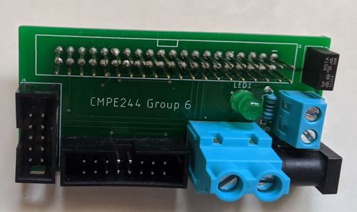
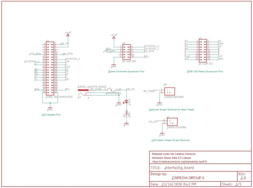
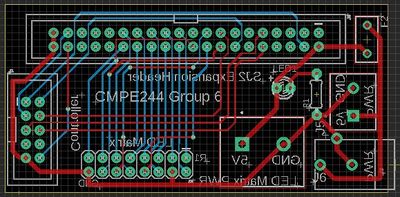
| Line 445: | Line 461: | ||
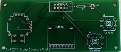
The controller board is designed to be a narrow rectangular so the footprint of the board is as small as possible, yet give enough space for hands to grab confortably. The board is a standard two-layer board with silkscreen on both sides. Similar to the interface board, we went with JLC (https://jlcpcb.com/) to manufacture our board. | The controller board is designed to be a narrow rectangular so the footprint of the board is as small as possible, yet give enough space for hands to grab confortably. The board is a standard two-layer board with silkscreen on both sides. Similar to the interface board, we went with JLC (https://jlcpcb.com/) to manufacture our board. | ||
| − | |||
== Hardware Interface == | == Hardware Interface == | ||
| Line 454: | Line 469: | ||
|[[File:fall2020_group6_LED_matrix.JPG|300x|thumb|left|64 X 64 LED Matrix]] | |[[File:fall2020_group6_LED_matrix.JPG|300x|thumb|left|64 X 64 LED Matrix]] | ||
|[[File:fall2020_group6_matrix_pins.JPG|200x|thumb|left|LED Matrix Pinout]] | |[[File:fall2020_group6_matrix_pins.JPG|200x|thumb|left|LED Matrix Pinout]] | ||
| + | |} | ||
| + | |||
| + | {| class="wikitable" style="margin-left: 0px; margin-right: auto;" | ||
| + | |- style="vertical-align: top;" | ||
| + | ! colspan="5" style="background:#000000;" | | ||
| + | <span style="color:#FFFFFF"> SJ2 LED Matrix Pin Connection</span> | ||
| + | |- | ||
| + | ! scope="col" style="text-align: center;" style="background:#C0C0C0;" | | ||
| + | LED Matrix Pin | ||
| + | ! scope="col" style="text-align: center" style="background:#C0C0C0;" | | ||
| + | SJ2 Pin | ||
| + | ! scope="col" style="text-align: center;" style="background:#C0C0C0;" | | ||
| + | Usage | ||
| + | |||
| + | |- | ||
| + | |- style="vertical-align: top;" | ||
| + | ! scope="row" style="text-align: left;" | | ||
| + | R1 | ||
| + | | style="text-align: left;" | | ||
| + | P2.0 | ||
| + | | style="text-align: left;" | | ||
| + | Upper screen red color | ||
| + | |||
| + | |- | ||
| + | |- style="vertical-align: top;" | ||
| + | ! scope="row" style="text-align: left;" | | ||
| + | G1 | ||
| + | | style="text-align: left;" | | ||
| + | P2.1 | ||
| + | | style="text-align: left;" | | ||
| + | Upper screen green color | ||
| + | |||
| + | |- | ||
| + | |- style="vertical-align: top;" | ||
| + | ! scope="row" style="text-align: left;" | | ||
| + | B1 | ||
| + | | style="text-align: left;" | | ||
| + | P2.2 | ||
| + | | style="text-align: left;" | | ||
| + | Upper screen blue color | ||
| + | |||
| + | |- | ||
| + | |- style="vertical-align: top;" | ||
| + | ! scope="row" style="text-align: left;" | | ||
| + | R2 | ||
| + | | style="text-align: left;" | | ||
| + | P2.4 | ||
| + | | style="text-align: left;" | | ||
| + | Lower screen red color | ||
| + | |||
| + | |- | ||
| + | |- style="vertical-align: top;" | ||
| + | ! scope="row" style="text-align: left;" | | ||
| + | G2 | ||
| + | | style="text-align: left;" | | ||
| + | P2.5 | ||
| + | | style="text-align: left;" | | ||
| + | Lower screen green color | ||
| + | |||
| + | |- | ||
| + | |- style="vertical-align: top;" | ||
| + | ! scope="row" style="text-align: left;" | | ||
| + | B1 | ||
| + | | style="text-align: left;" | | ||
| + | P2.6 | ||
| + | | style="text-align: left;" | | ||
| + | Lower screen blue color | ||
| + | |||
| + | |- | ||
| + | |- style="vertical-align: top;" | ||
| + | ! scope="row" style="text-align: left;" | | ||
| + | A | ||
| + | | style="text-align: left;" | | ||
| + | P2.7 | ||
| + | | style="text-align: left;" | | ||
| + | Pixel multiplexer selection bit | ||
| + | |||
| + | |- | ||
| + | |- style="vertical-align: top;" | ||
| + | ! scope="row" style="text-align: left;" | | ||
| + | B | ||
| + | | style="text-align: left;" | | ||
| + | P2.8 | ||
| + | | style="text-align: left;" | | ||
| + | Pixel multiplexer selection bit | ||
| + | |||
| + | |- | ||
| + | |- style="vertical-align: top;" | ||
| + | ! scope="row" style="text-align: left;" | | ||
| + | C | ||
| + | | style="text-align: left;" | | ||
| + | P2.9 | ||
| + | | style="text-align: left;" | | ||
| + | Pixel multiplexer selection bit | ||
| + | |||
| + | |- | ||
| + | |- style="vertical-align: top;" | ||
| + | ! scope="row" style="text-align: left;" | | ||
| + | D | ||
| + | | style="text-align: left;" | | ||
| + | P1.20 | ||
| + | | style="text-align: left;" | | ||
| + | Pixel multiplexer selection bit | ||
| + | |||
| + | |- | ||
| + | |- style="vertical-align: top;" | ||
| + | ! scope="row" style="text-align: left;" | | ||
| + | E | ||
| + | | style="text-align: left;" | | ||
| + | P1.23 | ||
| + | | style="text-align: left;" | | ||
| + | Pixel multiplexer selection bit | ||
| + | |||
| + | |- | ||
| + | |- style="vertical-align: top;" | ||
| + | ! scope="row" style="text-align: left;" | | ||
| + | LAT | ||
| + | | style="text-align: left;" | | ||
| + | P1.30 | ||
| + | | style="text-align: left;" | | ||
| + | Signal to latch display color shift register | ||
| + | |||
| + | |- | ||
| + | |- style="vertical-align: top;" | ||
| + | ! scope="row" style="text-align: left;" | | ||
| + | CLK | ||
| + | | style="text-align: left;" | | ||
| + | P1.29 | ||
| + | | style="text-align: left;" | | ||
| + | Signal to synchronize bit shift into display color shift register | ||
| + | |||
| + | |- | ||
| + | |- style="vertical-align: top;" | ||
| + | ! scope="row" style="text-align: left;" | | ||
| + | OE | ||
| + | | style="text-align: left;" | | ||
| + | P0.16 | ||
| + | | style="text-align: left;" | | ||
| + | Signal to enable/disable display | ||
| + | |||
|} | |} | ||
| Line 487: | Line 642: | ||
===== MP3 Decoder Module ===== | ===== MP3 Decoder Module ===== | ||
| + | |||
| + | {| | ||
| + | |[[File:fall2020_group6_mp3.PNG|300px|thumb|left|MP3 Decoder Module]] | ||
| + | |} | ||
| + | |||
| + | {| | ||
| + | | | ||
| + | {| class="wikitable" style="margin-left: 0px; margin-right: auto;" | ||
| + | |- style="vertical-align: top;" | ||
| + | ! colspan="5" style="background:#000000;" | | ||
| + | <span style="color:#FFFFFF"> SJ2 Master Board to SJ2 MP3 Board Pin Connection</span> | ||
| + | |- | ||
| + | ! scope="col" style="text-align: center;" style="background:#C0C0C0;" | | ||
| + | SJ2 Master Board Pin | ||
| + | ! scope="col" style="text-align: center" style="background:#C0C0C0;" | | ||
| + | SJ2 MP3 Board Pin | ||
| + | |||
| + | |- | ||
| + | |- style="vertical-align: top;" | ||
| + | ! scope="row" style="text-align: left;" | | ||
| + | P2.2 | ||
| + | | style="text-align: left;" | | ||
| + | P0.15 | ||
| + | |||
| + | |- | ||
| + | |- style="vertical-align: top;" | ||
| + | ! scope="row" style="text-align: left;" | | ||
| + | P2.4 | ||
| + | | style="text-align: left;" | | ||
| + | P0.17 | ||
| + | |||
| + | |- | ||
| + | |- style="vertical-align: top;" | ||
| + | ! scope="row" style="text-align: left;" | | ||
| + | P2.4 | ||
| + | | style="text-align: left;" | | ||
| + | P0.18 | ||
| + | |||
| + | |- | ||
| + | |- style="vertical-align: top;" | ||
| + | ! scope="row" style="text-align: left;" | | ||
| + | P2.4 | ||
| + | | style="text-align: left;" | | ||
| + | P0.22 | ||
| + | |||
| + | |} | ||
| + | |||
| + | | | ||
| + | {| class="wikitable" style="margin-left: 0px; margin-right: auto;" | ||
| + | |- style="vertical-align: top;" | ||
| + | ! colspan="5" style="background:#000000;" | | ||
| + | <span style="color:#FFFFFF"> SJ2 MP3 Board Pin Music Selection</span> | ||
| + | |- | ||
| + | ! scope="col" style="text-align: center;" style="background:#C0C0C0;" | | ||
| + | P2.2 | ||
| + | ! scope="col" style="text-align: center" style="background:#C0C0C0;" | | ||
| + | P2.4 | ||
| + | ! scope="col" style="text-align: center" style="background:#C0C0C0;" | | ||
| + | P2.5 | ||
| + | ! scope="col" style="text-align: center" style="background:#C0C0C0;" | | ||
| + | P2.6 | ||
| + | ! scope="col" style="text-align: center" style="background:#C0C0C0;" | | ||
| + | Music Name | ||
| + | |||
| + | |- | ||
| + | |- style="vertical-align: top;" | ||
| + | ! scope="row" style="text-align: left;" | | ||
| + | 0 | ||
| + | | style="text-align: left;" | | ||
| + | 0 | ||
| + | | style="text-align: left;" | | ||
| + | 0 | ||
| + | | style="text-align: left;" | | ||
| + | 0 | ||
| + | | style="text-align: left;" | | ||
| + | N/A | ||
| + | |||
| + | |- | ||
| + | |- style="vertical-align: top;" | ||
| + | ! scope="row" style="text-align: left;" | | ||
| + | 1 | ||
| + | | style="text-align: left;" | | ||
| + | 0 | ||
| + | | style="text-align: left;" | | ||
| + | 0 | ||
| + | | style="text-align: left;" | | ||
| + | 0 | ||
| + | | style="text-align: left;" | | ||
| + | BGM Music | ||
| + | |||
| + | |- | ||
| + | |- style="vertical-align: top;" | ||
| + | ! scope="row" style="text-align: left;" | | ||
| + | 0 | ||
| + | | style="text-align: left;" | | ||
| + | 1 | ||
| + | | style="text-align: left;" | | ||
| + | 0 | ||
| + | | style="text-align: left;" | | ||
| + | 0 | ||
| + | | style="text-align: left;" | | ||
| + | Dead Sound | ||
| + | |||
| + | |- | ||
| + | |- style="vertical-align: top;" | ||
| + | ! scope="row" style="text-align: left;" | | ||
| + | 0 | ||
| + | | style="text-align: left;" | | ||
| + | 0 | ||
| + | | style="text-align: left;" | | ||
| + | 1 | ||
| + | | style="text-align: left;" | | ||
| + | 0 | ||
| + | | style="text-align: left;" | | ||
| + | Eat Sound | ||
| + | |||
| + | |- | ||
| + | |- style="vertical-align: top;" | ||
| + | ! scope="row" style="text-align: left;" | | ||
| + | 0 | ||
| + | | style="text-align: left;" | | ||
| + | 0 | ||
| + | | style="text-align: left;" | | ||
| + | 0 | ||
| + | | style="text-align: left;" | | ||
| + | 1 | ||
| + | | style="text-align: left;" | | ||
| + | Faster Music | ||
| + | |||
| + | |} | ||
| + | |||
| + | |} | ||
| + | |||
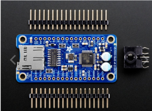
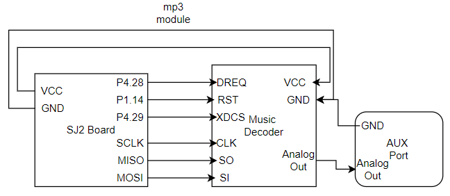
| + | There are two SJ2 boards involved in the game console - a master board that takes care of everything related to gameplay, and a slave board whose only task is to play music. We decided on this configuration because of reading experiences from past team, where having a mp3 play task slows down all other tasks within FreeRTOS. | ||
| + | |||
| + | Four GPIO pins connect the master board and the mp3 board together. When the game starts, master board sends a high signal on P0.15 to the mp3 board to trigger the BGM music playing. As gameplay continues, GPIO signals are sent to the mp3 board to trigger different sounds: | ||
| + | *BGM music - this sound used in normal gameplay, as well as the game start screen | ||
| + | *eat sound - this sound is triggered when snake eats a fruit | ||
| + | *dead sound - this sound is triggered when snake dies from running into an obstacle or itself | ||
| + | *faster music - this sound is played when player snake goes into battle mode with an enemy snake | ||
| + | |||
| + | {| class="wikitable" style="margin-left: 0px; margin-right: auto;" | ||
| + | |- style="vertical-align: top;" | ||
| + | ! colspan="5" style="background:#000000;" | | ||
| + | <span style="color:#FFFFFF"> SJ2 MP3 Board to Decoder Pin Connection</span> | ||
| + | |- | ||
| + | ! scope="col" style="text-align: center;" style="background:#C0C0C0;" | | ||
| + | SJ2 MP3 Board Pin | ||
| + | ! scope="col" style="text-align: center" style="background:#C0C0C0;" | | ||
| + | Decoder Pin | ||
| + | ! scope="col" style="text-align: center" style="background:#C0C0C0;" | | ||
| + | Usage | ||
| + | |||
| + | |- | ||
| + | |- style="vertical-align: top;" | ||
| + | ! scope="row" style="text-align: left;" | | ||
| + | P4.28 | ||
| + | | style="text-align: left;" | | ||
| + | DREQ | ||
| + | | style="text-align: left;" | | ||
| + | If high, data can now be sent to the decoder module | ||
| + | |||
| + | |- | ||
| + | |- style="vertical-align: top;" | ||
| + | ! scope="row" style="text-align: left;" | | ||
| + | P1.14 | ||
| + | | style="text-align: left;" | | ||
| + | RST | ||
| + | | style="text-align: left;" | | ||
| + | Decoder Module Reset | ||
| + | |||
| + | |- | ||
| + | |- style="vertical-align: top;" | ||
| + | ! scope="row" style="text-align: left;" | | ||
| + | P4.29 | ||
| + | | style="text-align: left;" | | ||
| + | XDCS | ||
| + | | style="text-align: left;" | | ||
| + | Decoder Data chip select | ||
| + | |||
| + | |- | ||
| + | |- style="vertical-align: top;" | ||
| + | ! scope="row" style="text-align: left;" | | ||
| + | P0.7 | ||
| + | | style="text-align: left;" | | ||
| + | SPI SCK | ||
| + | | style="text-align: left;" | | ||
| + | MP3 Module Clock | ||
| + | |||
| + | |- | ||
| + | |- style="vertical-align: top;" | ||
| + | ! scope="row" style="text-align: left;" | | ||
| + | P0.8 | ||
| + | | style="text-align: left;" | | ||
| + | SPI MISO | ||
| + | | style="text-align: left;" | | ||
| + | MP3 Module master out slave in | ||
| + | |||
| + | |- | ||
| + | |- style="vertical-align: top;" | ||
| + | ! scope="row" style="text-align: left;" | | ||
| + | P0.9 | ||
| + | | style="text-align: left;" | | ||
| + | SPI MOSI | ||
| + | | style="text-align: left;" | | ||
| + | MP3 Module master in slave out | ||
| + | |||
| + | |} | ||
| + | |||
| + | [[File:MP3.png]] | ||
== Software Design == | == Software Design == | ||
| Line 597: | Line 962: | ||
After obtaining the z-axis acceleration value, we can then compare it with earth's gravity, which is 9.8 m/s^2. If the gravity differs greatly from this value in both positive or negative directions, then this means the controller is being moved up or down. The faster the movement, the more difference between the two. We can then set up a threshold value, in which if the obtained acceleration is outside of the threshold, then movement is detected. | After obtaining the z-axis acceleration value, we can then compare it with earth's gravity, which is 9.8 m/s^2. If the gravity differs greatly from this value in both positive or negative directions, then this means the controller is being moved up or down. The faster the movement, the more difference between the two. We can then set up a threshold value, in which if the obtained acceleration is outside of the threshold, then movement is detected. | ||
| − | === | + | |
| − | + | === MP3 Decoder Module === | |
| + | |||
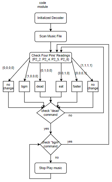
| + | On the SJ2 mp3 board side, the code flowchart is below. | ||
| + | |||
| + | [[File:code_flowchart.png]] | ||
| + | |||
| + | |||
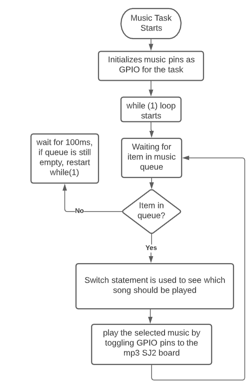
| + | On the master SJ2 board side, a music task is created to send signal to the mp3 SJ2 board. We decided to do a separate task because delay is needed when switching sounds in some cases, and we don't want the delay to affect rest of the gameplay. This task is low priority and involves a queue that stores the type of songs to play. When the main game wants to trigger a sound, it will call a function to send a variable of enum type "music_list" to the queue. the newly added item in the queue will then unlock the music task and a switch statement is used to find out which song to play. Then, the corresponding GPIO pin is toggled using music hookup functions, which is received by the mp3 board. | ||
| + | |||
| + | {| | ||
| + | |[[File:fall2020_group6_music_task.PNG|800px|thumb|left|Music Task]] | ||
| + | |} | ||
== Game Design == | == Game Design == | ||
| − | The code infrastructure is comprised of several major components that | + | The code infrastructure is comprised of several major components that allow you to create most types of games that do not involve projectiles or physics. If we were to extend the current game infrastructure, this would probably be the next task for us. |
=== Sprite Creation === | === Sprite Creation === | ||
| Line 622: | Line 998: | ||
int enemy_body_length = sizeof(enemy_body_parts) / sizeof(coordinates_t); | int enemy_body_length = sizeof(enemy_body_parts) / sizeof(coordinates_t); | ||
sprite_create_linked_bodies(enemy, enemy_body_parts, enemy_body_length); | sprite_create_linked_bodies(enemy, enemy_body_parts, enemy_body_length); | ||
| + | // Don't forget to add the sprite to the map once you are done configuring the coordinates and movement behavior | ||
add_sprite_to_map(map, enemy); | add_sprite_to_map(map, enemy); | ||
</syntaxhighlight> | </syntaxhighlight> | ||
| Line 627: | Line 1,004: | ||
=== Movement === | === Movement === | ||
| − | There are two modes of movement for the player: <b>on-demand</b> and <b>continuous</b> movement. In <b>on-demand | + | There are two modes of movement for the player: <b>on-demand</b> and <b>continuous</b> movement. In <b>on-demand</b> movement, the player sprite will be stationary until a direction input is detected. In <b>continuous</b> movement, the player sprite will constantly move in one direction until the player changes it. |
<syntaxhighlight lang="c"> | <syntaxhighlight lang="c"> | ||
| Line 638: | Line 1,015: | ||
A separate movement setting can be applied to either the player sprite or NPC that indicates whether the body will move in a <b>TRAIL</b> fashion similar to a snake, or <b>UNIT</b> fashion where all sprite body parts move in the same direction. It is import to note that when using <b>TRAIL</b> that the trailing will happen in the order that you specify the pixel coordinates due to the linked list implementation. | A separate movement setting can be applied to either the player sprite or NPC that indicates whether the body will move in a <b>TRAIL</b> fashion similar to a snake, or <b>UNIT</b> fashion where all sprite body parts move in the same direction. It is import to note that when using <b>TRAIL</b> that the trailing will happen in the order that you specify the pixel coordinates due to the linked list implementation. | ||
| + | |||
| + | Please note that the <b>move_type</b> field is only used for the player. The following is an example for setting the player movement type. | ||
<syntaxhighlight lang="c"> | <syntaxhighlight lang="c"> | ||
| Line 643: | Line 1,022: | ||
</syntaxhighlight> | </syntaxhighlight> | ||
| − | We have the capability to add advanced movement behaviors for NPCs. You can provide a list of behaviors and it will cycle through all the movements you specify in order. | + | Setting the movement type for NPCs require you to set the behavior. The following is an example to create an NPC that always moves as a <b>UNIT</b> to the right. |
| + | |||
| + | <syntaxhighlight lang="c"> | ||
| + | behavior_gen_t enemy_behavior_gen_info[] = {{UNIT, true, 1, {RIGHT}}}; | ||
| + | int enemy_behavior_length = sizeof(enemy_behavior_gen_info) / sizeof(behavior_gen_t); | ||
| + | sprite_create_move_behaviors(enemy, enemy_behavior_gen_info, enemy_behavior_length); | ||
| + | </syntaxhighlight> | ||
| + | |||
| + | We have the capability to add advanced movement behaviors for NPCs. You can provide a list of behaviors and it will cycle through all the movements you specify in order and keep repeating. | ||
<syntaxhighlight lang="c"> | <syntaxhighlight lang="c"> | ||
| Line 652: | Line 1,039: | ||
int enemy_behavior_length = sizeof(enemy_behavior_gen_info) / sizeof(behavior_gen_t); | int enemy_behavior_length = sizeof(enemy_behavior_gen_info) / sizeof(behavior_gen_t); | ||
sprite_create_move_behaviors(enemy, enemy_behavior_gen_info, enemy_behavior_length); | sprite_create_move_behaviors(enemy, enemy_behavior_gen_info, enemy_behavior_length); | ||
| + | </syntaxhighlight> | ||
| + | |||
| + | Currently, in order to change the direction that the player snake is moving, we need to access the internal structure and set the direction. | ||
| + | |||
| + | <syntaxhighlight lang="c"> | ||
| + | // We assume the first sprite is always the player | ||
| + | sprite_t *snake = map->sprite_list->sprite; | ||
| + | sprite_direction_set(snake, UP); | ||
</syntaxhighlight> | </syntaxhighlight> | ||
=== Collision Detection === | === Collision Detection === | ||
| − | We use a | + | We use a 55x64 (missing rows are reserved for the score indicator) grid for collision detection. We determine what should happen when two sprites collide based on each type. Currently, we only have the following sprite types: <b>SNAKE</b> (player), <b>OBSTACLE</b>, <b>ENEMY</b>, <b>FRUIT</b> (consumable). |
| + | |||
| + | <b>old_sprite</b> refers to the sprite that occupied the space first. <b>new_sprite</b> refers to the sprite that is trying to take its place. | ||
<syntaxhighlight lang="c"> | <syntaxhighlight lang="c"> | ||
| Line 674: | Line 1,071: | ||
=== Game Step === | === Game Step === | ||
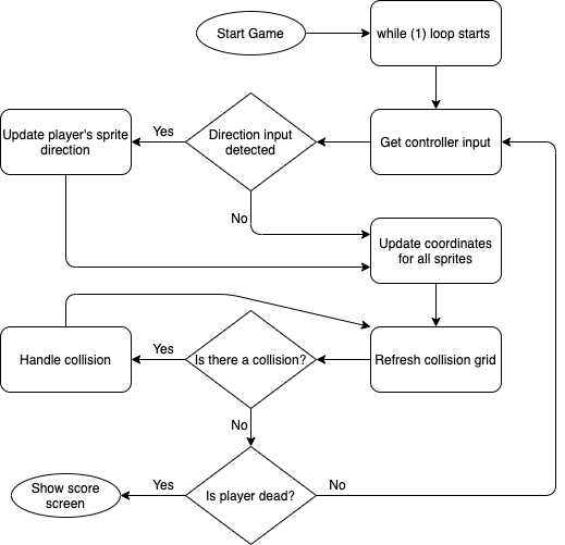
| − | + | The following code block shows a high level function that will be called from the outside to make progress in the game state by one tick. Each call to <b>game_step()</b> will internally call <b>sprite_step()</b> for each sprite on the map to update each body accordingly. | |
<syntaxhighlight lang="c"> | <syntaxhighlight lang="c"> | ||
| Line 684: | Line 1,081: | ||
walker = walker->next; | walker = walker->next; | ||
} | } | ||
| + | update_occupied_grid(gg); | ||
return gg->gameover; | return gg->gameover; | ||
} | } | ||
</syntaxhighlight> | </syntaxhighlight> | ||
| + | |||
| + | The following flow diagram shows a high level overview of our game logic. The <b>game_step</b> function above covers the steps for <b><i>Update coordinates for all sprites</i></b>, <b><i>Refresh collision grid</i></b>, and <b><i>Handle collision</i></b>. | ||
| + | |||
| + | [[File:hungry_snake_game_step.png|alt text]] | ||
| + | |||
| + | == Game Play Images == | ||
| + | |||
| + | {| | ||
| + | |[[File:fall2020_group6_gameplay.PNG|400px|thumb|left|Start Screen]] | ||
| + | |[[File:fall2020_group6_gameplay2.PNG|400px|thumb|left|Gameplay Screen (hard mode)]] | ||
| + | |} | ||
| + | |||
| + | {| | ||
| + | |[[File:fall2020_group6_gameplay3.PNG|400px|thumb|left|Gameplay Screen (easter egg)]] | ||
| + | |[[File:fall2020_group6_gameplay4.PNG|400px|thumb|left|End Screen]] | ||
| + | |} | ||
== Testing & Technical Challenges == | == Testing & Technical Challenges == | ||
| − | |||
| − | |||
| − | |||
| − | |||
=== LED Matrix unable to display more than 8 colors === | === LED Matrix unable to display more than 8 colors === | ||
| Line 698: | Line 1,108: | ||
At first, our aim was to have the LED matrix display a rainbow of different colors. Drawing from experience with the TRI-color LEDs, wrong assumption was made that the matrix behaves the same way. After hours of trying to hook up RGB pins to PWM output, the ghosting of colors were so bad that we had to give up the idea. The actual way of creating more color is probably through multi-bit register latching, which we didn't do because we didn't have a datasheet. Therefore, it is very important to obtain a datasheet before the start of LED matrix implementation. | At first, our aim was to have the LED matrix display a rainbow of different colors. Drawing from experience with the TRI-color LEDs, wrong assumption was made that the matrix behaves the same way. After hours of trying to hook up RGB pins to PWM output, the ghosting of colors were so bad that we had to give up the idea. The actual way of creating more color is probably through multi-bit register latching, which we didn't do because we didn't have a datasheet. Therefore, it is very important to obtain a datasheet before the start of LED matrix implementation. | ||
| − | === | + | === Debugging crashes due to NULL pointer access in linked list game implementation === |
| − | There were times we tried to put <b>fprintf</b> statements in various places in the code to see where it crashes. However, it was very time consuming to do this. Instead, we created a separate <b>Makefile</b> that uses a separate <b>main.c</b> and compile the code against | + | There were times where we tried to put <b>fprintf</b> statements in various places in the code to see where it crashes. However, it was very time consuming to do this. Instead, we created a separate <b>Makefile</b> that uses a separate <b>main.c</b> and compile the code against a hosted environment. This allows us to get a core dump and/or use GDB to inspect memory and walk through our code line by line. The game infrastructure doesn't know about any hardware details so this was not difficult to accomplish. |
== Conclusion == | == Conclusion == | ||
| − | + | ||
| + | This project was a great learning experience for us and taught us how to abstract the application (game) layer away from the hardware. When we needed to access certain hardware functions such as the sound or accelerometer, we hooked up callback functions in the game code. This allowed us the flexibility change the behavior by providing different callbacks. | ||
=== Project Video === | === Project Video === | ||
| − | + | ||
| + | *[https://youtu.be/BIKhQqS2Gwc Youtube Demo Video] | ||
=== Project Source Code === | === Project Source Code === | ||
| Line 712: | Line 1,124: | ||
* [https://gitlab.com/sjsugroup6/group6-hungry-snake/-/tree/origin/music/yanshen Separate branch for music decoder] | * [https://gitlab.com/sjsugroup6/group6-hungry-snake/-/tree/origin/music/yanshen Separate branch for music decoder] | ||
| − | |||
=== Acknowledgement === | === Acknowledgement === | ||
| − | |||
| − | |||
| − | |||
| − | |||
| − | + | We would like to thank Preet for being such a wonderful instructor for us. Without the knowledge we learned in the class, we would never be able to create this game console. | |
| − | |||
Latest revision as of 22:48, 18 December 2020
Contents
Abstract
This project involves using the SJ2 boards used in CMPE244 class to create a playable game console. The game we created is derived from the classic snake game, in which a snake moves around in the play area, eating fruits to expand its body. We also made additions to the game to extend the game's functionality and playability.
The game is composed of an 3D-printed enclosure, with two boards - one master SJ2 board tasked with gameplay and display, and another SJ2 board tasked with mp3 music play. The game display utilizes a 64 x 64 LED matrix, and player controls the snake via a controller with joystick, button, and accelerometer sensor input.
Basic Gameplay
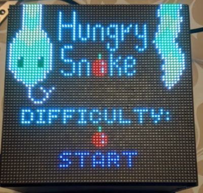
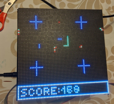
The player plays a snake that is constantly moving in a direction and its body will move in a trailing fashion. The goal of the game is survive as long as possible. You will attain points over time and additional points if you "eat" a fruit or enemy. As you eat more objects, the snake's body will extend so that it will become more difficult over time. A new fruit will be randomly generated in the map as you consume them.
There are moving obstacles as well for the player snake to avoid. If the player collides with any obstacle, they instantly die.
Enemy snakes with alternating red and yellow colors spawn in the map at higher difficulty. A battle is triggered when the player snake runs into an enemy snake. When the battle starts, a progress bar appears at the bottom of the screen. The player needs to shake the controller up and down as fast as possible to "battle" the enemy snake, which will fill the progress bar. If there is no shaking, the progress bar will be continually drained. If the progress bar is drained, the player loses. If the progress bar is filled by shaking the controller, the player successfully overcame the snake and the game returns back to normal gameplay. The enemy snake you defeated will be removed and a new one will be spawned at a new location.
Scoring
- Your score increases by your score multiplier per tick of the game. Initially, this value will be 1.
- Your score increases by 100 for eating a fruit. Additionally, your multiplier will increase by 1.
- Your score increases by 1000 for defeating an enemy snake. Additionally, your multiplier will increase by 1.
Game Over Condition
- You collide with an obstacle
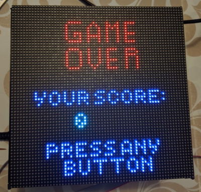
- You lose a battle with an enemy snake
- You collide with a part of your own body
Bonus Stage
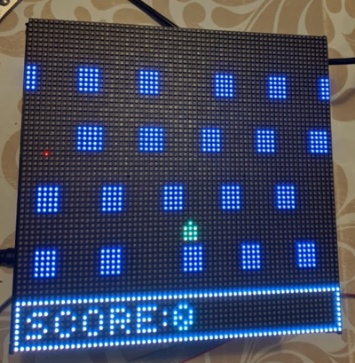
We have created a bonus stage to demonstrate our map creation framework. The game resembles frogger where you have to avoid moving cars. In this game mode, you only earn points (100) for eating fruits. Continuous score accumulation over time is disabled in this mode.
Team Members & Responsibilities
- Yang ChenIn
- Game Development, Code Repo Management
- Yanshen Luo
- Hardware Development, Music Module, Mechanical Parts(3D Design & 3D Printing)
- David Tang
- Game Development
- Nuoya Xie
- Hardware Development - LED Matrix, Controller, PCB Design, and Music Hookup Code
Schedule
|
TEAM SCHEDULE | ||||
|---|---|---|---|---|
|
Week# |
Date |
Task |
Status | |
| 1 | 10/10/20 |
|
| |
| 2 | 10/17/20 |
|
| |
| 3 | 10/24/20 |
|
| |
| 4 | 10/31/20 |
|
| |
| 5 | 11/7/20 |
|
| |
| 6 | 11/14/20 |
|
| |
| 7 | 11/21/20 |
|
| |
| 8 | 11/28/20 |
|
| |
| 9 | 12/5/20 |
|
| |
| 10 | 12/12/20 |
|
| |
| 11 | 12/16/20 |
|
| |
Parts List & Cost
|
Top Level | ||||
|---|---|---|---|---|
|
PART NAME |
PART MODEL & SOURCE |
QUANTITY |
COST PER UNIT (USD) | |
| 64x64 RGB LED Matrix* | Adafruit | 1 | $54.95 | |
| 5V 5A PSU | Amazon | 1 | $14.99 | |
| SJ2 Board | - | 2 | FREE (each team member has his/her own) | |
| 10 pin IDC flat Ribbon Cable | Amazon | 1 roll | $7.99 | |
| 2x5 FC-10P 2.54mm Dual Rows IDC Sockets Female Connector | Amazon | 2 | $0.46 | |
| Hamburger Mini Speaker | Sparkfun | 1 | $4.95 | |
| VS1053 Codec + MicroSD Breakout | Adafruit | 1 | $24.95 | |
|
Interface Board | ||||
|---|---|---|---|---|
|
Item # |
PART NAME |
PART SOURCE |
QUANTITY |
COST PER UNIT (USD) |
| 1 | 2 x 20 (40 Pin) Extra Tall Female 0.1 Inch Pitch Stacking Header | Amazon | 1 | $1.375 |
| 2 | 2X5 10Pins 2.54mm Pitch Straight Pin Connector IDC Header | Amazon | 1 | $0.24 |
| 3 | 2X8 16Pins 2.54mm Pitch Straight Pin Connector IDC Header | Amazon | 1 | $0.28 |
| 4 | TB006-508-02BE Screw Terminal Block | DIGIKEY | 1 | $0.77 |
| 5 | RSTA 3.15 AMMO Fuse | DIGIKEY | 1 | $0.28 |
| 6 | TB005-762-02BE Screw Terminal Block | DIGIKEY | 1 | $0.85 |
| 7 | 2.1mm Barrel Jack Female | DIGIKEY | 1 | $0.71 |
| 8 | 2.1mm Barrel Jack Female (Breadboard Compatible) | Provided by Yanshen Luo | 1 | Free |
| 9 | 3mm LED | Provided by Nuoya Xie | 1 | Free |
| 10 | 680Ω resistor | Provided by Nuoya Xie | 1 | Free |
|
Controller Board | ||||
|---|---|---|---|---|
|
Item # |
PART NAME |
PART SOURCE |
QUANTITY |
COST PER UNIT (USD) |
| 1 | Analog 2-axis Thumb Joystick w/ select button | AMAZON | 1 | $1.6 |
| 2 | 12x12x7.3 mm Tactile Push Button | AMAZON | 2 | $0.64 |
| 3 | 2X5 10Pins 2.54mm Pitch Straight Pin Connector IDC Header | Amazon | 1 | $0.24 |
| 4 | LSM303 Triple-Axis Accelerometer | DIGIKEY | 1 | $14.95 |
| 5 | standoff with accompany screw and nut | Provided by Nuoya Xie | 2 | Free |
| 6 | 2.5mm Female Headers (1x8) | Provided by Yanshen Luo | 1 | Free |
| 7 | 3mm LED | Provided by Nuoya Xie | 1 | Free |
| 8 | 330Ω resistor | Provided by Nuoya Xie | 1 | Free |
Design & Implementation
Overview
The game console consists the following hardware components:
- Two SJ2 boards - one for gameplay, one for mp3
- One wired controller with joystick, two buttons, and an accelerometer on board
- 64x64 LED Matrix Display
- MP3 Decoder module
- 5V Power Supply
- One interfacing board connecting all components to the master SJ2 board
Interface Board Design
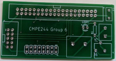
The purpose of the interface board is to provide stable, permanent connection to the SJ2 board. It includes connections to all the components that are necessary for the game to run. Below are the components of the interface board:
- 2x20 0.1" pin header to connect to the SJ2 board
- 3.15A fuse to prevent high current passing through the components, in case of an electrical short
- IDC 2x8 shroud connector to the LED matrix signal pins
- Screw terminals for power to the LED matrix(5V), as well as 5V inlet power from power supply
- Optional 2.1mm DC barrel jack for 5V inlet power. Either this jack or the screw terminal can be used to feed power into the interface board
- LED with a current-limiting resistor, indicting when power is provided to the board
In order to save manufacturing costs, the interface board is designed so the footprint of the board is as small as possible. The board is a standard two-layer board with silkscreen on both sides. We went with JLC (https://jlcpcb.com/) to manufacture our board.
Controller Board Design
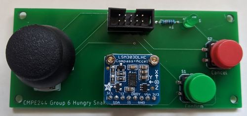
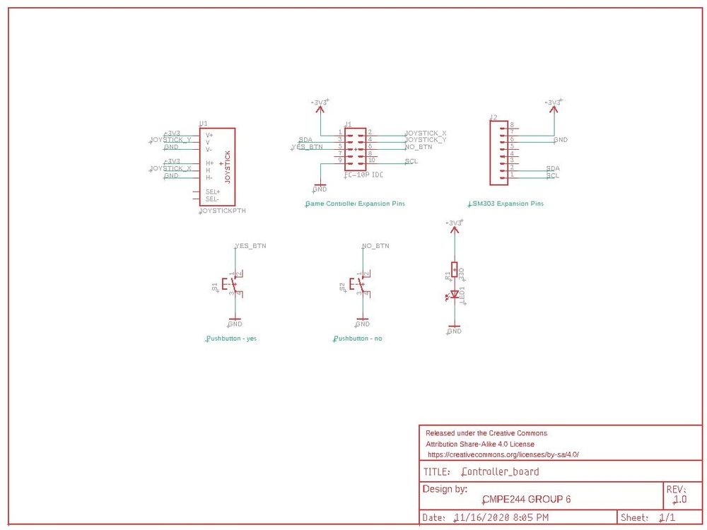
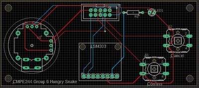
The purpose of the controller board is to obtain user feedback to the game. Similar to a real controller, the controller board contains one joystick that can detect five different directions (up, down, left, right, and center). This is used to control movement of the snake in game. Two buttons, confirm(green) and cancel(red) are included on the board so they can be used to select options on the opening screen. An accelerometer, LSM303, is attached to the controller board through female headers for the ease of removal, in the event which the accelerometer needs to be replaced. The controller board also contains an LED to indicate that the board has been supplied of power. The communication between the controller board and the interface board is through and IDC 10-pin header and ribbon cable. The reason why flat ribbon cable is selected is because the crimper, header, and wire for such cable is cheap and readily available.
The controller board is designed to be a narrow rectangular so the footprint of the board is as small as possible, yet give enough space for hands to grab confortably. The board is a standard two-layer board with silkscreen on both sides. Similar to the interface board, we went with JLC (https://jlcpcb.com/) to manufacture our board.
Hardware Interface
LED Matrix Display
|
SJ2 LED Matrix Pin Connection | ||||
|---|---|---|---|---|
|
LED Matrix Pin |
SJ2 Pin |
Usage | ||
|
R1 |
P2.0 |
Upper screen red color | ||
|
G1 |
P2.1 |
Upper screen green color | ||
|
B1 |
P2.2 |
Upper screen blue color | ||
|
R2 |
P2.4 |
Lower screen red color | ||
|
G2 |
P2.5 |
Lower screen green color | ||
|
B1 |
P2.6 |
Lower screen blue color | ||
|
A |
P2.7 |
Pixel multiplexer selection bit | ||
|
B |
P2.8 |
Pixel multiplexer selection bit | ||
|
C |
P2.9 |
Pixel multiplexer selection bit | ||
|
D |
P1.20 |
Pixel multiplexer selection bit | ||
|
E |
P1.23 |
Pixel multiplexer selection bit | ||
|
LAT |
P1.30 |
Signal to latch display color shift register | ||
|
CLK |
P1.29 |
Signal to synchronize bit shift into display color shift register | ||
|
OE |
P0.16 |
Signal to enable/disable display | ||
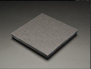
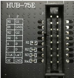
We chose an 64 x 64 LED Matrix from Adafruit, because we wanted the number of pixels to be as many as possible. The display is controlled by an 2x8 IDC header, which has the following pins:
- R1, G1, B1 - Pins controlling Red, Green, and Blue colors for the upper half of the matrix (32 x 64 LEDs)
- R2, G2, B2 - Pins controlling Red, Green, and Blue colors for the lower half of the matrix (32 x 64 LEDs)
- A, B, C, D, E - Multiplexer pins selecting a single row of the matrix (2 ^ 5 = 32 rows)
- CLK - Clock signal that indicating each shift into the shift register of the LED matrix
- LAT - Once data is shifted into the shift register of the LED matrix, this pin latches the data so they won't be altered
- OE - Output Enable. Used to on the selected row's LEDs on or off
Because we are using 1 bit for each color, a total of 2^3 = 8 colors are available for us to pick from. This also means that all of the pins listed above are simply GPIO pins to control the LED matrix.
At any one point in time, 2 rows (1 on the upper half of the matrix and 1 on the bottom) are selected. These two rows are always off by 32. For example, if row 0 on the top half is selected, then row 0 on the bottom half, which is row 32, is also selected. This means at any one time, two rows are lighted up. However, because of the persistence of vision, human eye can only perceive image at and below 60Hz. This mean if we shift the bits fast enough, we are able to light up "all" of the LEDs on the matrix display.
Controller
Controller consists of:
- One joystick, capable of detecting 5 directions - up, down, left, right, and none (when the controller is not moved)
- Two buttons, one for confirming and one for cancelling of selected options on the start screen
- An accelerometer, LSM303, for detecting movement, such as the shaking of controller by user
Joystick consists of two potentiometers, one for horizontal and one for vertical. When user pushes the stick to a certain direction, both potentiometer contacts are swept across two contacts, creating two voltage dividers. Thus, by reading this voltage using two ADCs, the direction of horizontal and vertical movement can be calculated.
Buttons are connected to GPIO pins that are input direction with a pull-up resistor. When the button is pressed, the input line is connected to ground. Thus, by reading the input pins, if the pin is low, the button is pressed, and vice versa.
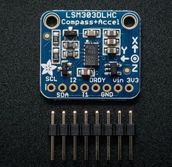
Accelerometer (LSM303) is used in this game to detect controller motion. The sensor can detect acceleration in the x, y, and z coordinate. In our application, we used the z coordinate acceleration to calculate if the controller is been moved up and down. The sensor communicates to the JS2 board using I2C protocol, which means SDA and SCL lines, on top of GND, are connected to the I2C2 peripheral of the microcontroller board.
MP3 Decoder Module
|
| ||||||||||||||||||||||||||||||||||||||||||||||||||
There are two SJ2 boards involved in the game console - a master board that takes care of everything related to gameplay, and a slave board whose only task is to play music. We decided on this configuration because of reading experiences from past team, where having a mp3 play task slows down all other tasks within FreeRTOS.
Four GPIO pins connect the master board and the mp3 board together. When the game starts, master board sends a high signal on P0.15 to the mp3 board to trigger the BGM music playing. As gameplay continues, GPIO signals are sent to the mp3 board to trigger different sounds:
- BGM music - this sound used in normal gameplay, as well as the game start screen
- eat sound - this sound is triggered when snake eats a fruit
- dead sound - this sound is triggered when snake dies from running into an obstacle or itself
- faster music - this sound is played when player snake goes into battle mode with an enemy snake
|
SJ2 MP3 Board to Decoder Pin Connection | ||||
|---|---|---|---|---|
|
SJ2 MP3 Board Pin |
Decoder Pin |
Usage | ||
|
P4.28 |
DREQ |
If high, data can now be sent to the decoder module | ||
|
P1.14 |
RST |
Decoder Module Reset | ||
|
P4.29 |
XDCS |
Decoder Data chip select | ||
|
P0.7 |
SPI SCK |
MP3 Module Clock | ||
|
P0.8 |
SPI MISO |
MP3 Module master out slave in | ||
|
P0.9 |
SPI MOSI |
MP3 Module master in slave out | ||
Software Design
Show your software design. For example, if you are designing an MP3 Player, show the tasks that you are using, and what they are doing at a high level. Do not show the details of the code. For example, do not show exact code, but you may show psuedocode and fragments of code. Keep in mind that you are showing DESIGN of your software, not the inner workings of it.
LED Matrix Display
In order to control the LED matrix and give each pixel its color, the user has to:
- Select which row (on both top and bottom half of the matrix) using pins A ~ E
- Disable output on this row of LEDs by setting OE pin
- Unlatch data by setting the LAT pin
- For each pixel on the row, clear first, then shift the desired bits into R1, G1, B1, R2, G2, and B2 pins. Set and Reset the CLK pin for each LED.
- Enable output by resetting the OE pin
- Have some delay. The longer the delay, the brighter the pixel will be
- Lastly, disable output by setting the OE pin
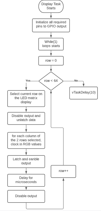
All of this code is encapsulated into a function, which is called by a FreeRTOS display task that has highest priority and runs every 10ms. The flow diagram of the display tasks is shown below.
Below is the code describing the steps above.
void led_matrix__refreshDisplay(void) {
  for (uint8_t row = 0; row < LED_MATRIX_HALF_LENGTH; row++) {

    led_matrix__select_row(row);
    led_matrix__disable_output();
    led_matrix__unlatch_data();
    led_matrix__clock_in_data(row);
    led_matrix__latch_data();
    led_matrix__enable_output();
    delay__us(100);
    led_matrix__disable_output();
  }
}
Select Row function:
void led_matrix__select_row(uint8_t row) {
  // set all rows to low first
  LPC_GPIO1->PIN &= ~(1 << D.pin | 1 << E.pin);
  LPC_GPIO2->PIN &= ~(1 << A.pin | 1 << B.pin | 1 << C.pin);

  // row number selected using A to E (5 bits)
  LPC_GPIO2->PIN |= (((row >> 0) & 0x1) << A.pin | ((row >> 1) & 0x1) << B.pin | ((row >> 2) & 0x1) << C.pin);
  LPC_GPIO1->PIN |= (((row >> 3) & 0x1) << D.pin | ((row >> 4) & 0x1) << E.pin);
}
Below is the clock in data function:
void led_matrix__clock_in_data(uint8_t row) {
    for (uint8_t col = 0; col < LED_MATRIX_FULL_LENGTH; col++) {
        LPC_GPIO2->PIN &= ~((1 << R1.pin) | (1 << R2.pin) | (1 << G1.pin) | (1 << G2.pin) | (1 << B1.pin) | (1 << B2.pin));

        LPC_GPIO2->PIN |= (display_matrix_top[row][col].R << R1.pin) | (display_matrix_bottom[row][col].R << R2.pin) |
                      (display_matrix_top[row][col].G << G1.pin) | (display_matrix_bottom[row][col].G << G2.pin) |
                      (display_matrix_top[row][col].B << B1.pin) | (display_matrix_bottom[row][col].B << B2.pin);

        lab_gpio__set(CLK.port, CLK.pin, true);
        lab_gpio__set(CLK.port, CLK.pin, false);
  }
}
Controller
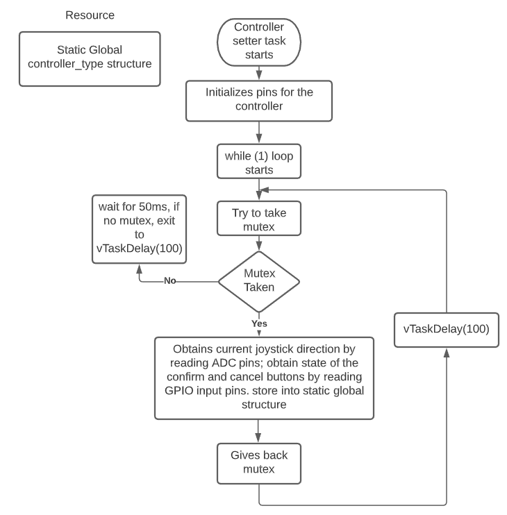
All of the controller-related actions are encapsulated in FreeRTOS tasks. A controller setter task obtains values from controller joystick and buttons and store it in a static global struct variable. The variable is then accessed by the game logic task using a driver function. The obtain controller value task run at 100ms and is low priority. A mutex is used between the setter/getter tasks to prevent simultaneous access to the resource.
Accelerometer
Accelerometer is a separate entity of the controller board - its value isn't obtained by the controller task. This is because usually motion detection using the sensor isn't needed at normal gameplay - it is only triggered when player is battling an enemy snake. Because of this, the task for motion detection is resumed and suspended by other tasks and it doesn't run in a loop.
In order to detect if player is shaking the controller, accelerometer data for the Z-axis is obtained by sending I2C commands to the sensor. According to sensor datasheet, which can be obtained here (https://cdn-shop.adafruit.com/datasheets/LSM303DLHC.PDF), X, Y, and Z-axis acceleration raw values can be obtained from registers 0x28 to 0x2D. Using build-in I2C driver, one can grab all of these bytes with one command. The obtained higher bits need to be shifted in order to recreate the 16-bit raw value, as seen below:
  uint8_t bytes_read[6] = {0};
  i2c__read_slave_data(I2C__2, ACCEL_ADDRESS, (1 << 7 | ACCEL_OUT_X_L_A), bytes_read, 6);
  // convert data to proper format
  int16_t accel_raw_data_X = (int16_t)(bytes_read[0] | (bytes_read[1] << 8));
  int16_t accel_raw_data_Y = (int16_t)(bytes_read[2] | (bytes_read[3] << 8));
  int16_t accel_raw_data_Z = (int16_t)(bytes_read[4] | (bytes_read[5] << 8));
In order to convert the raw value into an actual acceleration unit(m/s^2), a conversion equation is needed. Many internet sources are used to come up with the final equation, as shown below. This equation assumes that the sensor needs to be in 4G and normal mode, which can be configured by the user by writing to the CTRL_REG4_A(0x23) and CTRL_REG1_A(0x20) registers.
static float lsm303__calculate_acceleration_from_raw(int16_t raw_value) {
  const float lsb = 0.00782; // for 4G, normal mode
  const uint8_t shift = 6;   // for normal mode
  const float sensor_gravity_standard = 9.80665; //gravity of earth

  return (float)(raw_value >> shift) * lsb * sensor_gravity_standard;
}
After obtaining the z-axis acceleration value, we can then compare it with earth's gravity, which is 9.8 m/s^2. If the gravity differs greatly from this value in both positive or negative directions, then this means the controller is being moved up or down. The faster the movement, the more difference between the two. We can then set up a threshold value, in which if the obtained acceleration is outside of the threshold, then movement is detected.
MP3 Decoder Module
On the SJ2 mp3 board side, the code flowchart is below.
On the master SJ2 board side, a music task is created to send signal to the mp3 SJ2 board. We decided to do a separate task because delay is needed when switching sounds in some cases, and we don't want the delay to affect rest of the gameplay. This task is low priority and involves a queue that stores the type of songs to play. When the main game wants to trigger a sound, it will call a function to send a variable of enum type "music_list" to the queue. the newly added item in the queue will then unlock the music task and a switch statement is used to find out which song to play. Then, the corresponding GPIO pin is toggled using music hookup functions, which is received by the mp3 board.
Game Design
The code infrastructure is comprised of several major components that allow you to create most types of games that do not involve projectiles or physics. If we were to extend the current game infrastructure, this would probably be the next task for us.
Sprite Creation
This allows you to specify a body comprised of various pixel coordinates. The body may have gaps between different body parts. This is useful for simulating multiple sprites using a single object which can be moved together.
NOTE: Right now we always expect the first sprite to be the player sprite. The following code block is just an example.
  game_grid_t *map = calloc(1, sizeof(game_grid_t));
  sprite_t *enemy = calloc(1, sizeof(sprite_t));
  enemy->type = ENEMY;
  enemy->speed = 8;
  enemy->length = 5;
  enemy->max_length = 10;
  enemy->wrap_around = true;

  coordinates_t enemy_body_parts[] = {{38, 20}, {39, 20}, {40, 20}, {41, 20}, {42, 20}};
  int enemy_body_length = sizeof(enemy_body_parts) / sizeof(coordinates_t);
  sprite_create_linked_bodies(enemy, enemy_body_parts, enemy_body_length);
  // Don't forget to add the sprite to the map once you are done configuring the coordinates and movement behavior
  add_sprite_to_map(map, enemy);
Movement
There are two modes of movement for the player: on-demand and continuous movement. In on-demand movement, the player sprite will be stationary until a direction input is detected. In continuous movement, the player sprite will constantly move in one direction until the player changes it.
  sprite_t *player = calloc(1, sizeof(sprite_t));
  player->type = SNAKE;
  player->continuous_movement = true;
  // Set initial direction
  player->dir = LEFT;
A separate movement setting can be applied to either the player sprite or NPC that indicates whether the body will move in a TRAIL fashion similar to a snake, or UNIT fashion where all sprite body parts move in the same direction. It is import to note that when using TRAIL that the trailing will happen in the order that you specify the pixel coordinates due to the linked list implementation.
Please note that the move_type field is only used for the player. The following is an example for setting the player movement type.
player->move_type = TRAIL;Setting the movement type for NPCs require you to set the behavior. The following is an example to create an NPC that always moves as a UNIT to the right.
  behavior_gen_t enemy_behavior_gen_info[] = {{UNIT, true, 1, {RIGHT}}};
  int enemy_behavior_length = sizeof(enemy_behavior_gen_info) / sizeof(behavior_gen_t);
  sprite_create_move_behaviors(enemy, enemy_behavior_gen_info, enemy_behavior_length);
We have the capability to add advanced movement behaviors for NPCs. You can provide a list of behaviors and it will cycle through all the movements you specify in order and keep repeating.
  behavior_gen_t enemy_behavior_gen_info[] = {
      {TRAIL, true, 5, {RIGHT, RANDOM, RIGHT, RANDOM, RIGHT}},
      {TRAIL, true, 5, {UP, RANDOM, UP, RANDOM, UP}},
      {UNIT, true, 10, {RANDOM, RANDOM, RANDOM, RANDOM, NONE, NONE, RANDOM, RANDOM, RANDOM, RANDOM}}};
  int enemy_behavior_length = sizeof(enemy_behavior_gen_info) / sizeof(behavior_gen_t);
  sprite_create_move_behaviors(enemy, enemy_behavior_gen_info, enemy_behavior_length);
Currently, in order to change the direction that the player snake is moving, we need to access the internal structure and set the direction.
  // We assume the first sprite is always the player
  sprite_t *snake = map->sprite_list->sprite;
  sprite_direction_set(snake, UP);
Collision Detection
We use a 55x64 (missing rows are reserved for the score indicator) grid for collision detection. We determine what should happen when two sprites collide based on each type. Currently, we only have the following sprite types: SNAKE (player), OBSTACLE, ENEMY, FRUIT (consumable).
old_sprite refers to the sprite that occupied the space first. new_sprite refers to the sprite that is trying to take its place.
  collision_status_t sprite_collision(game_grid_t *gg, int x, int y, sprite_t *old_sprite, sprite_t *new_sprite) {
    ...
    if (old_sprite->type == SNAKE && new_sprite->type == OBSTACLE) {
      if (gg->dead_sound) {
        gg->dead_sound();
      }
      old_sprite->dead = true;
      return OLD_DIES;
    }
    ...
  }
Game Step
The following code block shows a high level function that will be called from the outside to make progress in the game state by one tick. Each call to game_step() will internally call sprite_step() for each sprite on the map to update each body accordingly.
  bool game_step(game_grid_t *gg) {
    sprite_list_t *walker = gg->sprite_list;

    while (walker) {
      sprite_step(walker->sprite);
      walker = walker->next;
    }
    update_occupied_grid(gg);
    return gg->gameover;
  }
The following flow diagram shows a high level overview of our game logic. The game_step function above covers the steps for Update coordinates for all sprites, Refresh collision grid, and Handle collision.
Game Play Images
Testing & Technical Challenges
LED Matrix unable to display more than 8 colors
At first, our aim was to have the LED matrix display a rainbow of different colors. Drawing from experience with the TRI-color LEDs, wrong assumption was made that the matrix behaves the same way. After hours of trying to hook up RGB pins to PWM output, the ghosting of colors were so bad that we had to give up the idea. The actual way of creating more color is probably through multi-bit register latching, which we didn't do because we didn't have a datasheet. Therefore, it is very important to obtain a datasheet before the start of LED matrix implementation.
Debugging crashes due to NULL pointer access in linked list game implementation
There were times where we tried to put fprintf statements in various places in the code to see where it crashes. However, it was very time consuming to do this. Instead, we created a separate Makefile that uses a separate main.c and compile the code against a hosted environment. This allows us to get a core dump and/or use GDB to inspect memory and walk through our code line by line. The game infrastructure doesn't know about any hardware details so this was not difficult to accomplish.
Conclusion
This project was a great learning experience for us and taught us how to abstract the application (game) layer away from the hardware. When we needed to access certain hardware functions such as the sound or accelerometer, we hooked up callback functions in the game code. This allowed us the flexibility change the behavior by providing different callbacks.
Project Video
Project Source Code
Acknowledgement
We would like to thank Preet for being such a wonderful instructor for us. Without the knowledge we learned in the class, we would never be able to create this game console.
