Difference between revisions of "S20: Nimble"
(→Bluetooth send) |
(→Team Members & Responsibilities) |
||
| (5 intermediate revisions by the same user not shown) | |||
| Line 78: | Line 78: | ||
*** ''LCD display'' | *** ''LCD display'' | ||
*** ''Sensor Module'' | *** ''Sensor Module'' | ||
| + | *** ''Bridge Module'' | ||
** ''RC Integration and testing'' | ** ''RC Integration and testing'' | ||
** '' Wiki '' | ** '' Wiki '' | ||
| Line 1,175: | Line 1,176: | ||
* '''Issue 3:''' The checkpoints set using google maps for our area used for testing were shifted when doing physical testing with the RC car. This was due to the poor accuracy of the GPS despite our efforts in performing some manual calibration of the GPS. | * '''Issue 3:''' The checkpoints set using google maps for our area used for testing were shifted when doing physical testing with the RC car. This was due to the poor accuracy of the GPS despite our efforts in performing some manual calibration of the GPS. | ||
**'''Solution:''' The solution, although not perfect, was to set an offset to the original checkpoints such that the newly shifted coordinates would reflect the checkpoints originally set using google maps. | **'''Solution:''' The solution, although not perfect, was to set an offset to the original checkpoints such that the newly shifted coordinates would reflect the checkpoints originally set using google maps. | ||
| + | |||
| + | * ''' Issue 4: ''' Another issue encountered was the failure of connecting to the mobile application in time of the demo. | ||
| + | ** ''' Solution:''' The only solution we had was to hardcode GPS coordinates for the destination instead. | ||
<HR> | <HR> | ||
| Line 1,245: | Line 1,249: | ||
Sending data to the HC-05 module is done by using the uart__put() method provided in the sjtwo-c development environment from Preet. | Sending data to the HC-05 module is done by using the uart__put() method provided in the sjtwo-c development environment from Preet. | ||
| + | <center> | ||
<table> | <table> | ||
<tr> | <tr> | ||
<td> | <td> | ||
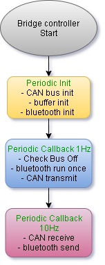
| − | [[File:Bluetooth send.jpg|thumb|450px| | + | [[File:Bluetooth send.jpg|thumb|450px|center|''' Bridge controller software flow-chart''']] |
</td> | </td> | ||
</tr> | </tr> | ||
</table> | </table> | ||
| + | </center> | ||
=== Technical Challenges === | === Technical Challenges === | ||
| Line 1,516: | Line 1,522: | ||
* '''Unit Testing''': | * '''Unit Testing''': | ||
** We learned the Unity and CMOCK framework, and how to unit-test our code modules which sped up the development of the components of the project. In particular, the GPS and Compass were thought to be the hardest to get working, but with an early start and unit-testing, these modules faced little issues to get working. The only difficulties as mentioned before was the calibration and accuracy. | ** We learned the Unity and CMOCK framework, and how to unit-test our code modules which sped up the development of the components of the project. In particular, the GPS and Compass were thought to be the hardest to get working, but with an early start and unit-testing, these modules faced little issues to get working. The only difficulties as mentioned before was the calibration and accuracy. | ||
| − | ** We believe that this is by far the most useful and interesting | + | ** We believe that this is by far the most useful and interesting experience that we have encountered this semester. Although we're still not experts on writing flawless unit-tests, it doesn't change the fact of how incredibly revolutionary and useful it was during our project. |
* '''GIT''': | * '''GIT''': | ||
** We learned all the basic go GIT and it helps us collaborate on the different modules virtually without physical meeting. (Because of Corona Virus) | ** We learned all the basic go GIT and it helps us collaborate on the different modules virtually without physical meeting. (Because of Corona Virus) | ||
| − | + | Although there were some problems encountered while doing this project, we were able to finish the majority of the basic tasks required of the project. Unfortunately, we were not able to implement the mobile application as a requirement due to some issues encountered with the connectivity of the Bluetooth module which occurred in the last week of the project. Additionally, because of the COVID-19 outbreak, classes had to be conducted through google hangouts for the rest of the semester. The outbreak also made it difficult to meet physically with teammates which made it difficult to not only integrate and test the RC car, but it also reduced involvement in the project of every teammate. Despite these shortcomings of the project, the overall experience was fun and interesting. The class and project helped us learn a TON of new concepts and skills that will prove valuable in the future and industry. | |
| − | |||
=== Project Video === | === Project Video === | ||
| Line 1,533: | Line 1,538: | ||
=== Advice for Future Students === | === Advice for Future Students === | ||
| − | * '''Advice 1:''' Always make sure the teammate you choose is responsible | + | * '''Advice 1:''' Always make sure the teammate you choose is responsible since '''teammate is the most important part of this group project'''. If any teammate is not responsible, make sure you pursue them and keep track of their progress. Otherwise, you will end up finishing their lack of progress. Also, make sure you get your teammates' contact information, besides slack, like phone or text messages. |
* '''Advice 2: ''' ''' Set an earlier deadline ''' and make sure your teammates finish before the deadline. ''' There should be no tolerance ''' because this project will be more difficult when there is a lack of contribution from team members. If there are no strong leaders within your team, the result of your project will not be great. Also, assign important tasks, like GPS and Mobile application, to someone with the most knowledge and reliability, since those two are by far the most difficult part of the RC car. A rough draft of the ''' mobile application should be highly considered early on. Especially if nobody in your team has experience in mobile app development. ''' It is HIGHLY recommended to refer to the previous semesters' team to get a ''' GOOD LOOK ''' of ''' Preet's expectations '''. | * '''Advice 2: ''' ''' Set an earlier deadline ''' and make sure your teammates finish before the deadline. ''' There should be no tolerance ''' because this project will be more difficult when there is a lack of contribution from team members. If there are no strong leaders within your team, the result of your project will not be great. Also, assign important tasks, like GPS and Mobile application, to someone with the most knowledge and reliability, since those two are by far the most difficult part of the RC car. A rough draft of the ''' mobile application should be highly considered early on. Especially if nobody in your team has experience in mobile app development. ''' It is HIGHLY recommended to refer to the previous semesters' team to get a ''' GOOD LOOK ''' of ''' Preet's expectations '''. | ||
Latest revision as of 04:45, 23 May 2020
Contents
- 1 Nimble Autonomous RC Car
- 2 Abstract
- 3 Team Members & Responsibilities
- 4 Team Deliverables Schedule
- 5 Parts List & Cost
- 6 Printed Circuit Board
- 7 CAN Communication
- 8 Sensor ECU
- 9 Motor ECU
- 10 Geographical Controller
- 11 Communication Bridge Controller
- 12 Driver Controller & LCD
- 13 Mobile Application
- 14 Conclusion
Nimble Autonomous RC Car
Abstract
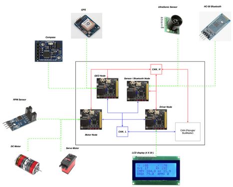
In this project, an autonomous vehicle framework for an RC car is presented using dedicated ECUs for motor control, on-board LCD display, steering control, sensor information handling, and communication bridging. A mobile application was also developed that allows for a user to set a destination, and receive updates on the RC car's position via a Bluetooth connection to the GPS unit. CAN communication between sensors and ECUs was defined via a DBC file. Code was developed using test-driven design principles in order to lower time spent debugging. Unit testing was performed using the CMock framework.
Introduction
The project was divided into these modules:
- Sensor node
- Motor node
- Driver node
- GPS node
- Bridge control node
- LCD node
- Mobile application
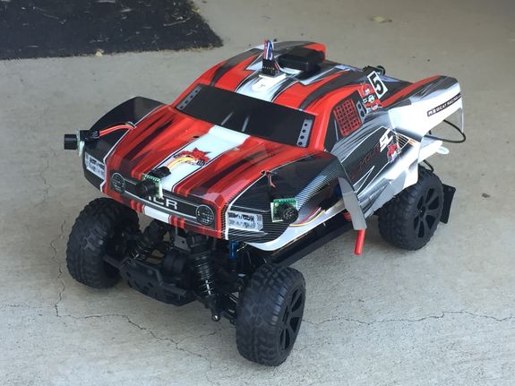
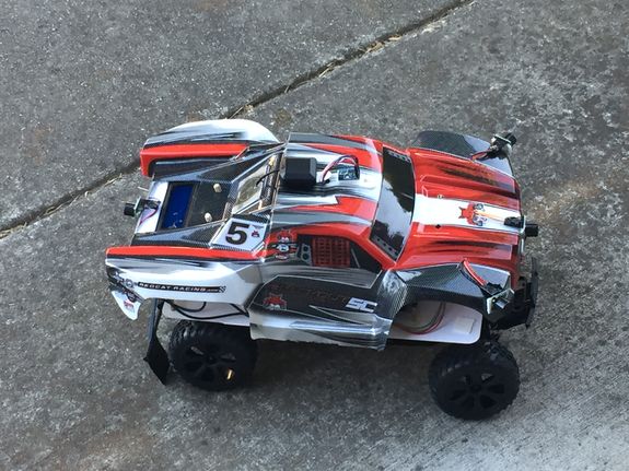
The objective was to create an autonomous vehicle that could navigate to a given GPS coordinate sent via a mobile application. The vehicle moves towards the target position Using a pre-compiled list of checkpoints, and handles obstacles along the way via its ultrasonic and infrared sensors. Updates on Nimble's position are sent to the mobile application via bluetooth.
Team Members & Responsibilities
- Yuming Cheng Gitlab
- Motor Module
- GPS Module
- Driver Module (Master Module)
- LCD display
- RC Integration and testing
- Wiki
- Motor Module
- Naeem Mannan Gitlab
- Wiki
- Mobile Application
- Bridge Controller
- Francesco Vescio Gitlab
- Wiki
- Code Review
- Lawrence Wan LinkedIn Gitlab
- GPS Module
- Driver Module (Master Module)
- Motor Module
- LCD display
- Sensor Module
- Bridge Module
- RC Integration and testing
- Wiki
Team Deliverables Schedule
| WEEK |
START DATE |
END DATE |
TASK DETAILS |
STATUS |
|---|---|---|---|---|
| 1 | Feb 2020 | 4 March 2020 |
|
|
| 2 | 05 March 2020 | 12 March 2020 |
|
|
| 3 | 13 March 2020 | 19 March 2020 |
|
|
| 4 | 20 March 2020 | 26 March 2020 |
|
|
| 5 | 27 March 2019 | 09 April 2019 |
|
|
| 6 | 10 April 2020 | 16 April 2020 |
|
|
| 7 | 17 April 2020 | 23 April 2020 |
|
|
| 8 | 24 April 2020 | 30 April 2020 |
|
|
| 9 | 1 May 2020 | 7 May 2020 |
|
|
| 10 | 8 May 2020 | 21 May 2020 |
|
|
| 11 | 22 May 2020 |
|
|
Parts List & Cost
| Item# | Part Desciption | Vendor | Qty | Cost |
|---|---|---|---|---|
| 1 | RC Car | Traxxas - Amazon [1] | 1 | $168.84 |
| 2 | CAN Transceivers MCP2551-I/P | Robotshop [2] | 6 | $ 6.00 per unit including shipping fee |
| 3 | GPS & Antenna | Amazon [] | 1 | $ 78.24 including shipping fee |
| 4 | Compass | Amazon [] | 1 | $ 41.48 including shipping fee |
| 5 | Ultrasonic sensors(LV-MaxSonar-EZ0) | SparkFun [3] | 1 | $ 29.95 |
| 6 | Ultrasonic sensors (LV-MaxSonar-EZ1) | SparkFun [4] | 2 | $ 51.90 |
| 7 | IR sensors (GP2Y0A21YK) | SparkFun [5] | 1 | $ 34.23 including shipping fee and tax |
| 8 | PCB Fabrication | JLCPCB | 5 | $ 39.13 including shipping fee and tax |
| 9 | IR Optocoupler | Amazon | 5 | $ 40.01 including one day shipping fee and tax |
| 10 | 20x4 LCD Display | Adafruit [6] | 5 | $ 0.00 (Provided by Naeem Mannan) |
Printed Circuit Board
Design and Architecture
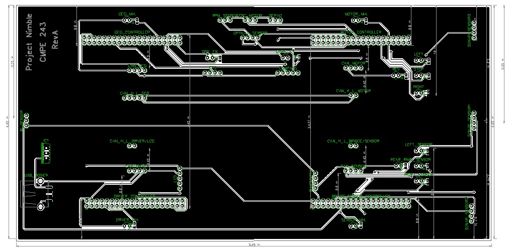
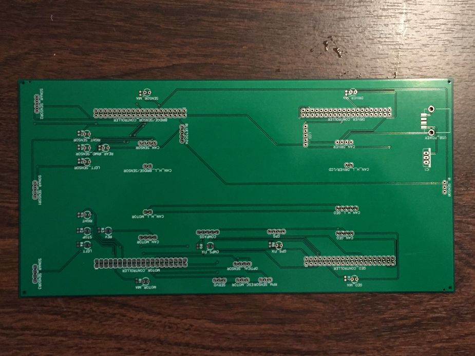
The PCB made for the Project Nimble RC car was initially designed in EAGLE, however, due to the board size limitations, the PCB had to be designed using DipTrace instead. This design was the first and only iteration in designing the layout of the PCB. The design of the PCB was designed around the four SJTWO LPC4078 micro-controllers required for us to use for the project, the DRIVER, MOTOR, GEOGRAPHICAL, and BRIDGE/SENSOR nodes. The PCB layout consists of four through-hole "slots" where the controllers will be connected (with respect to the controllers' orientation and ports/pins) to the PCB. The power section includes a USB socket as well as a through-hole mount for a LM7805 regulator. Through-hole header pins are also included for the components needed for their respective controllers such as the sensors, LCD, GPS, Compass, etc.. LED circuits were added to provide visual information for the user to indicate the motor and servo motion states, as well as to indicate if a sensor has detected an object. Lastly, the design for the CAN bus includes the connections needed for power, RX/TX, and the CAN low and CAN high bus. The dimensions of the PCB are approximately 4 by 9 inches.
Fabrication
Fabrication of the PCB design was done by JLCPCB located in Hong Kong. The PCB was designed using 2-layers and lead-free coating. The fabrication was done relatively quickly, however, due to the COVID-19 outbreak, delivery of the PCB was delayed.
Challenges
Some challenges encountered when designing the PCB was the delay in pinout information needed to begin designing the PCB. It is advised to order parts early and determine what ports/pins are needed as soon as possible to begin designing and ordering the PCB. Another challenge was some issues with the files needed to be manufactured. Since the design had to be designed using DipTrace instead of EAGLE, exporting the necessary files needed to order for fabrication is slightly different than EAGLE.
CAN Communication
All the controllers on Nimble communicate with each other via CAN(control area network) bus with termination resistors. 120-ohm termination resistors avoid signal reflection. Can is basically a broadcast bus that operates on standard baud rates like 100K, 125K, 250K, 500K, or 1Mbps. It is based on half-duplex communication over a differential pair.
CAN communication is based on the priority of messages in case of bus arbitration. A lower ID message always has a higher priority. Nimble’s DBC is shown in the next section which is used to generate CAN messages
To detect modules that are missing in action due to error in reception, MIA is configured. It replaces the data with safe values when the communication cuts off. Below is an example snippet of code that configures CAN MIA for the driver controller which sets default values for data sent from the sensor, geographical, and motor controller. It also configures a mia threshold which is the amount of time that should pass before an MIA should occur and replace the values for its respective module data structure.
 const uint32_t dbc_mia_threshold_SENSOR_DATA = 10 * 100;
 const uint32_t dbc_mia_threshold_COMPASS = 10 * 100;
 const uint32_t dbc_mia_threshold_MOTOR_DATA = 10 * 100;

 const dbc_SENSOR_DATA_s dbc_mia_replacement_SENSOR_DATA = {};

 const dbc_COMPASS_s dbc_mia_replacement_COMPASS = {};

 const dbc_MOTOR_DATA_s dbc_mia_replacement_MOTOR_DATA = {};
Hardware Design
DBC File
Shown below is the DBC implementation for this project.
VERSION ""

NS_ :
	BA_
	BA_DEF_
	BA_DEF_DEF_
	BA_DEF_DEF_REL_
	BA_DEF_REL_
	BA_DEF_SGTYPE_
	BA_REL_
	BA_SGTYPE_
	BO_TX_BU_
	BU_BO_REL_
	BU_EV_REL_
	BU_SG_REL_
	CAT_
	CAT_DEF_
	CM_
	ENVVAR_DATA_
	EV_DATA_
	FILTER
	NS_DESC_
	SGTYPE_
	SGTYPE_VAL_
	SG_MUL_VAL_
	SIGTYPE_VALTYPE_
	SIG_GROUP_
	SIG_TYPE_REF_
	SIG_VALTYPE_
	VAL_
	VAL_TABLE_

BS_:

BU_: DBG DRIVER IO MOTOR SENSOR BRIDGE GPS COMPASS CMP

BO_ 150 MOTOR_CMD: 3 DRIVER
 SG_ MOTOR_CMD_STEERING : 0|8@1+ (1,-2) [-2|2] "" MOTOR
 SG_ MOTOR_CMD_SPEED : 8|8@1+ (1,-25) [-25|25] "" MOTOR

BO_ 151 MOTOR_DATA: 4 MOTOR
 SG_ MOTOR_DATA_RPM: 0|32@1+ (1,0) [0|0] "" DRIVER

BO_ 200 SENSOR_DATA: 8 BRIDGE
 SG_ SENSOR_SONARS_left : 0|16@1+ (1,0) [0|0] "cms" DRIVER
 SG_ SENSOR_SONARS_mid : 16|16@1+ (1,0) [0|0] "cms" DRIVER
 SG_ SENSOR_SONARS_right : 32|16@1+ (1,0) [0|0] "cms" DRIVER
 SG_ SENSOR_IR_rear : 48|16@1+ (1,0) [0|0] "cms" DRIVER

BO_ 300 GPS_DESTINATION_INFO: 8 BRIDGE
SG_ GPS_DESTINATION_LAT : 0|32@1+ (0.000001,-90.000000) [-90|90] "degrees" DRIVER,GPS,MOTOR
SG_ GPS_DESTINATION_LONG : 32|32@1+ (0.000001,-180.000000) [-180|180] "degrees" DRIVER,GPS,MOTOR

BO_ 301 GPS_CURRENT_INFO: 8 GPS
SG_ GPS_CURRENT_LAT : 0|32@1+ (0.000001,-90.000000) [-90|90] "degrees" DRIVER,BRIDGE,MOTOR
SG_ GPS_CURRENT_LONG : 32|32@1+ (0.000001,-180.000000) [-180|180] "degrees" DRIVER,BRIDGE,MOTOR

BO_ 302 COMPASS: 6 GPS
 SG_ CMP_DEST_BEARING : 0|16@1+ (0.1,0) [0|359.9] "degrees" DRIVER,BRIDGE,MOTOR
 SG_ CMP_CURRENT_HEADING : 16|16@1+ (0.1,0) [0|359.9] "degrees" DRIVER,BRIDGE,MOTOR
 SG_ CMP_DISTANCE : 32|16@1+ (0.01,0) [0|0] "meters" DRIVER,BRIDGE

BO_ 105 SENSOR_DEBUG: 1 BRIDGE
 SG_ IO_DEBUG_CAN_init : 0|1@1+ (1,0) [0|0] "" DBG
 SG_ IO_DEBUG_sensor_init : 1|1@1+ (1,0) [0|0] "" DBG
 SG_ IO_DEBUG_sensor_data : 2|1@1+ (1,0) [0|0] "" DBG
 SG_ IO_DEBUG_bus_off : 3|1@1+ (1,0) [0|0] "" DBG

BO_ 106 MOTOR_DEBUG: 6 MOTOR
 SG_ IO_DEBUG_CAN_init : 0|1@1+ (1,0) [0|0] "" DBG,DRIVER
 SG_ IO_DEBUG_bus_off : 1|1@1+ (1,0) [0|0] "" DBG,DRIVER
 SG_ IO_DEBUG_Steering : 2|8@1+ (1,-2) [-2|2] "" DBG,DRIVER
 SG_ IO_DEBUG_RPM : 10|32@1+ (1,0) [0|0] "" DBG,DRIVER

BO_ 107 DRIVER_DEBUG: 1 DRIVER
 SG_ IO_DEBUG_CAN_init : 0|1@1+ (1,0) [0|0] "" DBG
 SG_ IO_DEBUG_bus_off : 1|1@1+ (1,0) [0|0] "" DBG
 SG_ IO_DEBUG_DRIVER : 3|1@1+ (1,0) [0|0] "" DBG

BO_ 108 GPS_DEBUG: 1 GPS
 SG_ IO_DEBUG_CAN_init : 0|1@1+ (1,0) [0|0] "" DBG
 SG_ IO_DEBUG_bus_off : 2|1@1+ (1,0) [0|0] "" DBG
 SG_ IO_DEBUG_GPS : 3|1@1+ (1,0) [0|0] "" DBG
 SG_ IO_DEBUG_Compass : 5|1@1+ (1,0) [0|0] "" DBG

BO_ 109 BRIDGE_DEBUG: 1 BRIDGE
 SG_ IO_DEBUG_CAN_init : 0|1@1+ (1,0) [0|0] "" DBG
 SG_ IO_DEBUG_bus_off : 2|1@1+ (1,0) [0|0] "" DBG
 SG_ IO_DEBUG_Bridge : 4|1@1+ (1,0) [0|0] "" DBG

CM_ BU_ DRIVER "The driver controller driving the car";
CM_ BU_ MOTOR "The motor controller of the car";
CM_ BU_ BRIDGE "The bridge controller of the car";
CM_ BU_ GPS    "The GPS controller of the car";
CM_ BO_ 100 "Sync message used to synchronize the controllers";
CM_ SG_ 100 DRIVER_HEARTBEAT_cmd "Heartbeat command from the driver";

BA_DEF_ "BusType" STRING ;
BA_DEF_ BO_ "GenMsgCycleTime" INT 0 0;
BA_DEF_ SG_ "FieldType" STRING ;

BA_DEF_DEF_ "BusType" "CAN";
BA_DEF_DEF_ "FieldType" "";
BA_DEF_DEF_ "GenMsgCycleTime" 0;

BA_ "GenMsgCycleTime" BO_ 100 1000;
BA_ "FieldType" SG_ 100 DRIVER_HEARTBEAT_cmd "DRIVER_HEARTBEAT_cmd";

VAL_ 100 DRIVER_HEARTBEAT_cmd 2 "DRIVER_HEARTBEAT_cmd_REBOOT" 1 "DRIVER_HEARTBEAT_cmd_SYNC" 0 "DRIVER_HEARTBEAT_cmd_NOOP" ;
Busmaster
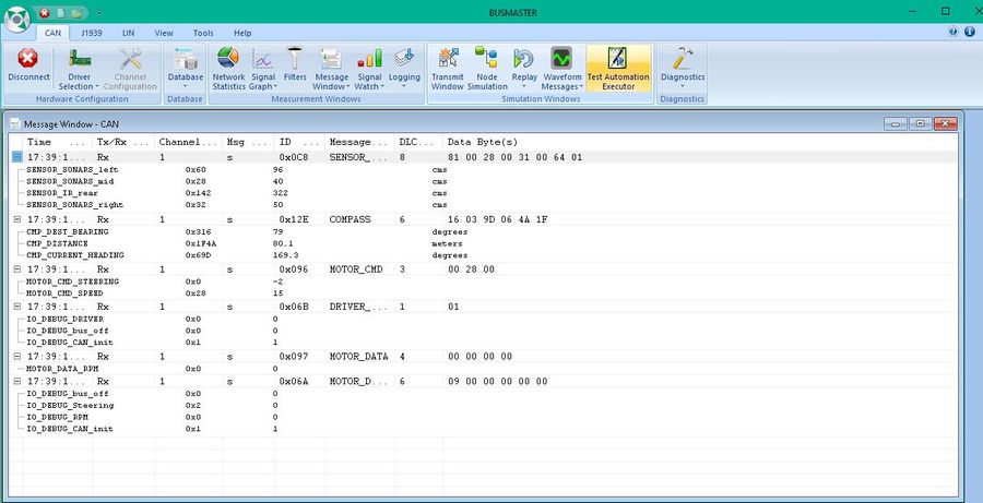
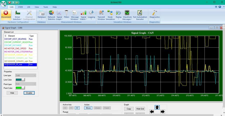
To monitor the messages being sent on the CAN-BUS, a PCAN dongle which Preet lent each group was used to connect to the CAN Bus and monitor messages being sent. The software used to monitor and analyze the messages sent on the CAN bus was Busmaster. An image of the busmaster message window and a signal graph is shown below.
Sensor ECU
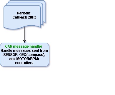
The sensor and bridge controller consists of sensor module that is responsible for object detection. Nimble uses ultrasonic sensors to achieve this task. As the name suggests, an ultrasonic sensor emits ultrasonic signal or beam from its head, and on encountering an object, returns back. This technique is better known as echolocation as we used sound signals to do so. The distance of the object is calculated based on the output and this ensures object detection. The distance measured is continuously passed on to driver node through can transceiver. The driver controller further processes the distance values of all the sensors on nimble and acts in accordance with the values to achieve obstacle avoidance.
Hardware Design
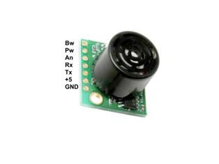
We have embedded 4 sensors on Nimble. We have arranged 3 LV-MaxSonar-EZ series Maxbotix ultrasonic sensors in the front section of the car; one at right, one at left and one in the center. The fourth Ultrasonic sensor is placed at the rear end of the car. These sensors provide very short to long-range detection. It provides sonar range information from 6-inches out to 254-inches with 1-inch resolution.
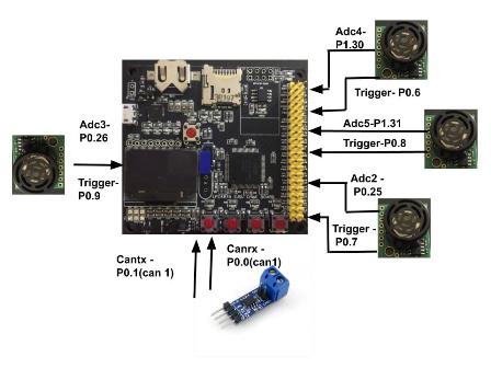
A maxbotix sensor gives out 3 types of output- analog, RS232, and Pulse width. We have used analog output and hence, utilized on-board analog to digital converters- ADC2 (P0.25), ADC3 (P0.26), ADC4 (P1.30), and ADC5 (P1.31). To trigger all the four ultrasonic sensors, we used P0.6, P0.7, P0.8 and P0.9 of SJTWO board. The analog output is converted to digital and transmitted to the driver controller. The converted adc distance data is passed to driver by Can transceiver. P0.0 is used as CAN RX and P0.1 as CAN TX on the Sensor module.
Hardware Interface
Sensors are interfaced with combination of GPIO, ADC Pins on SJTWo board. Below is the descriptive pin layout:
| Sr. No. | SJTwo board Pin | Maxbotix sensor Pin | Function |
|---|---|---|---|
| 1 | ADC2-P0.25 | AN(Left) | ADC input from left sensor |
| 2 | ADC3-P0.26 | AN(Rear) | ADC input from rear sensor |
| 3 | ADC4-P1.30 | AN(Right) | ADC input from right sensor |
| 4 | ADC5-P1.31 | AN(Middle) | ADC input from middle sensor |
| 5 | P0.6 | RX(Right) | Trigger for right sensor |
| 6 | P0.7 | RX(Left) | Trigger for left sensor |
| 7 | P0.8 | RX(Middle) | Trigger for middle sensor |
| 8 | P0.9 | RX(Rear) | Trigger for rear sensor |
Software Design
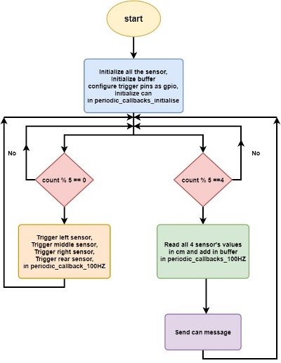
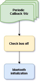
The sensor implementation is done in 100Hz callback function, part of the periodic callbacks module. To give an overview, all the sensors are triggered at once and then given a minimum buffer time of 30ms for the outbound signal to bounce back and get detected, thereby giving us the raw distance readings. These readings are then processed inside a buffer to send the minimum value over CAN at 20Hz. As we have used Analog output, we used the available onboard ADCs with a few changes to the ADC driver implemented by Preet. The SJTWO board has 4 ADC pins available, with P0.26, which can be configured as both an ADC and a DAC. So we configured P0.26, that is ADC3 channel into the code and modified the ADC driver accordingly. The ADC readings are in the form of raw voltage and hence are converted to distances in centimetres. To get the most accurate distance value of each sensor, we used a buffer that gives out the minimum distance reading at 20Hz. This distance is sent over CAN to the Driver Node which further processes these distances and triggers the motors accordingly. The flowchart below shows the implementation of our Sensor controller.
A. Initialization:
1. Initialization of sensors: As we are using onboard ADC to get voltage, we first initialize all the ADCs (ADC2, ADC 3, ADC 4, ADC 5). We then configured IOCON registers to set up all the ADCs, according to the LPC40xx datasheet.
2. Initialized Buffer and can.
B. Triggering the sensors:
1. Configured available SJTWO GPIO pins, to be connected to the sensor’s RX pin, as GPIO output. These pins will serve as trigger pins to the sensors.
2. The sensors are triggered in at 20Hz inside the 100Hz function. To do so, the trigger pin is set for 30ms and the reset.
C. Read sensor values:
We are using ADC values to obtain the distance. All the values are in the form of analog voltage and represents the number of steps in terms of voltage level. To get real voltage value from raw, it is multiplied by the ADC voltage and divided by voltage scaling defined by voltage level powering the sensors (here 3.3 V) and manufacturing scaling (Vcc/512). The distance values obtained are stored in the Circular buffer module. All the sensors have an individual buffer that collects the distance values and get the minimum of all the values.
D. CAN transmission:
The lowest distance in 'cm' of all the sensors is sent to driver controller over CAN bus. We have used CAN1 to achieve this task. The driver then coordinates the movement according to the distance value.
Technical Challenges
- Issue 1: Unreliable reading when the whole RC car is being powered by one single portable battery. IR sensor, which was to mounted as the rear sensor wasn't receiving enough power to work reliably.
- Solution: We ended up switching the IR sensor to another ultrasonic sensor, which works even at 3.3V, in order to make the rear readings reliable.
- Issue 2: Interference between the sensors was a major issue, wherein an obstacle on the right would make both the Right and Middle sensors to read low values.
- Future work: The best possible solution would be print sensor mounts in advance, after deciding upon the sensors to be used. This will ease the process of testing the RC car.
Motor ECU
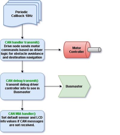
Our Motor Controller node is responsible to control the DC and Servo motor from the RC car, and additional RPM sensor measurement to get the RPM value from each rotation so we can have control to the speed or our RC car. The motor controller logic the steering and speed will be calculated within the Driver Node Controller through the CAN bus messages. Then, the Motor Controller node will output the feedback of RPM value for the Driver node to display the RPM value through CAN bus to the Driver module. The Motor controller node will also use this RPM feedback from the sensor to maintaining the speed making sure that the car is under certain threshold of RPM value, so it won't become too fast or too slow. The CAN message function will be constantly called at 10Hz of the periodic callbacks, while the speed check for the RPM value will be call every 500 ms.
Hardware Design
The hardware interface details of MOTOR Module with SJOne board are given above:
|
Hardware Interface
SERVO Motor
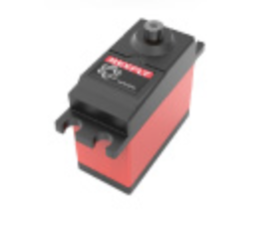
The direction of the RC car is dependent on the servo motor, based on various PWM signals of 10% to 20% it will steers the front wheels from right to left direction. The servo motor has 3 wires, where one is the PWM input signals, other two wires responsible to the VCC of 6V and Ground. We powered our Servo motor using the ESC output voltage from the Nickel Metal Hydride (NiMh) battery of the RC car, and the PWM signals will be generated from motor controller of P2.1 of SJtwo Board.
|
|
DC Motor
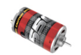
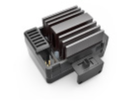
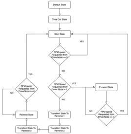
The DC motor is already connected with the ESC as default built-in from the RC car, the purpose of ESC (Electronic Speed Control) is to control the DC motor Using PWM signals from the controller. It also regulated (converted) the 7.4V NiMh battery power sources into stable 6V energy output for the DC motor and servo. The DC motor is similar to the Servo where it takes in 10% to 20% duty cycle of PWM signals to control the RC car Forward, Stop, and Reverse mode. One thing that's interesting is that there is certain sequence for the DC motor to go from Forward state into the Reverse state, based from the design of the ESC it is to protect the DC motor from breaking.
The sequence of the DC motor to go to Reverse is that it have to received the PWM of Reverse duty cycle for two times before it actually starting to go in reverse direction.
|
|
RPM Sensor
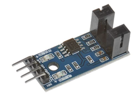
RPM sensor is the device that calculated the one single rotation per certain duration of time frame. It can be a device that used magnet to calculated one rotation or IR Optocoupler with its corresponding disk, as long as the device can successfully achieve the job of counting one rotation cycle. Our RPM sensor in mounted on the car shaft instead of the built-in RPM sensor from Traxxas, when ever the IR Optocoupler sending the signals to the P2.6 as the interrupts it will increment the rotation_count for the computation on the RPM value. The IR Optocoupler have 4 PIN, where we only used its VCC, GND, and D0 for our RC car, the VCC need power of 3.3V to 5V to properly power-up the device, and the GND should have common GND that connected all the devices, while D0 pin will goes to P2.6 in our Motor Controller.
|
Software Design
The dc motor and servo motor operation is fundamentally based on PWM (Pulse Width Modulation). We set the PWM frequency to 100Hz for both dc and servo motor.
Pseudo code for initializing PWM to 100Hz.
 gpio__construct_with_function(2, 0, 1);
 gpio__construct_with_function(2, 1, 1);
 // gpio input for interrupt
 gpio__construct_as_input(2, 6);
 // gpio initialize the interrput
 gpio2__attach_interrupt(6, GPIO_INTR__RISING_EDGE, pwm_get_speed);
 lpc_peripheral__enable_interrupt(LPC_PERIPHERAL__GPIO, pwm_get_speed, NULL);
pwm1__init_single_edge(frequency_in_hertz); // usually use 100 hz
Servo motor Pseudo Code
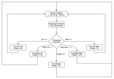
The servo motor is connected to the Pin 2.1 on SJTwo Board. The servo received the command of -2 to 2 from the can1 of driver node every 10 Hz, where the -2 represents full left and 0 as neutral and 2 as full right turn. Then the data from CAN bus of driver node will be process under if statement to select the respective rotation of the servo motor according to the data received from the driver logic. Under is some Pseudo logic of the function, once the rotation is finish selected it will use motor_control_status__process_data(); to choose the respective PWM of the Servo, where left would be 20 and right would 10 and 15 as neutral state of the servo motor.
 if (motor_cmd_data->MOTOR_CMD_STEERING == steer_left) {
   motor_control_status__process_data(MOTOR_STATUS_LEFT);
 } else if (motor_cmd_data->MOTOR_CMD_STEERING == steer_right) {
   motor_control_status__process_data(MOTOR_STATUS_RIGHT);
 } else if (motor_cmd_data->MOTOR_CMD_STEERING == steer_slight_left) {
   motor_control_status__process_data(MOTOR_STATUS_SLIGHTLY_LEFT);
 } else if (motor_cmd_data->MOTOR_CMD_STEERING == steer_slight_right) {
   motor_control_status__process_data(MOTOR_STATUS_SLIGHTLY_RIGHT);
 } else if (motor_cmd_data->MOTOR_CMD_STEERING == steer_straight) {
   motor_control_status__process_data(MOTOR_STATUS_STRAIGHT);
 }
DC motor Pseudo Code
The DC motor is connected to the Pin 2.0 on SJTwo Board. The DC received the command of PWM every 10 Hz, where the 20 represents full forward and 15 as neutral and 10 as full reverse. Because the value of DC motor when it is 20 or 10 would be too fast for the sensor to even react and transfer the signal to the motor node, we reduce the forward and reverse PWM as 15.5 for forward and 14.5 for reverse. The DC motor will be modify under the switch case state machine for FORWARD, REVERSE, STOP state of the DC motor. And the RPM sensor will be getting the speed of the RC car to increase or reduce the speed of the RC car in term of PWM. Below is partial code of the FORWARD state. The pwm_request_by_app will receive the speed request of from driver node in CAN1 bus, which will select and make the state change accordingly, and pwm_maintain_speed_forward(); will just be using the PWM sensor in the next section to monitor the rotation of the RC car so it doesn't be come too fast or too slow.
  if (0 >= pwm_request_by_app) {
     pwm_DC_motor(motor_speed_stop);
     pwm_servo_motor(servo_center);
     motor_value_type = MOTOR_STATUS_STOP;
     break;
   }
pwm_maintain_speed_forward();
RPM sensor Calculation Pseudo Code
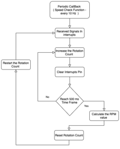
The RPM sensor is connected to the Pin 2.6 on SJTwo Board. It will received the signals from the every time it finish the single rotation. It will use interrupt to register these pulses in a 500ms time frame and then calculate the speed in m/s based on the formula:
rotation_per_min = rotation_value * ((60s * 1000hz "1 second")/duration_time) //where the duration_time is 500ms.
Because there is some difficulty in installing the magnet RPM sensor into the RC car, we end up using the LM393 Speed Detection Sensor Module with the Type IR Optocoupler and it's respective disks for the IR Optocoupler. So within one single rotation it will received 20 rotation_count, which them we will have to divided the rotation_count we received from the interrupt by 20 to get the actual one rotation from the wheel. The equation will be the following below.
rotation_value = rotation_count / 20;
And rotation_count will be received using code below.
 rotation_count = rotation_count + 1;
 clear_pin_interrupt2(6);
Technical Challenges
- Issue 1: One of the challenges to deal with in this project on the motor node, is probably the incompatibility of the RPM sensor from Traxxas. The RC car we got even thought it is from the Traxxas it doesn't have the slot for us to put in the RPM sensor and the magnet disk.
- Solution: We end up just using the IR Optocoupler and the middle car shaft that connect from the rear motor to the front wheel. The whole isn't perfect fit so we do have to make the hole for the disk larger and use glue gun to secure the location of the IR Optocoupler.
- Issue 2: Probably not the issue but more of what future work we could done to improve our current motor controller. As we run the DEMO there is overshoot problem when the RC trying to reach the checkpoints, due to not having implementation of PID controller.
- Future work: The solution would be increasing the CAN message commands of steering angle that Driver node sent to the motor node, and compute those angles from driver node to make variety of option for servo steering instead of just 5 options: slight left, left , slight right, right, and straight.
- Issue 3: Another future work that we could be doing, is that we notice during our demo our RC car will stop for a bit due to going over the threshold of RPM value on the RC car.
- Future work: There are two possible solution to this issues, first one is to make the increment and decrement of the maintain_speed function smaller, so it won't over shoot the RPM value generated from the RC car. Another solution is to adjust the RPM value of the threshold, so that it can be easier for the DC motor to main it's PWM.
Geographical Controller
The geographical controller is responsible for interfacing with a GPS and Compass module in order to receive the current heading(in degrees) and the current destination in the form of GPS coordinates (in degrees, hours, minutes, seconds). It is also responsible for receiving the needed destination coordinates sent by the BRIDGE controller which are needed along with the current GPS location coordinates to calculate the destination heading angle and distance to destination and checkpoints. The current compass heading angle is also sent to the DRIVER controller such that it can be integrated into the driver logic to determine the heading angle to steer and drive towards the destination.
Hardware Design
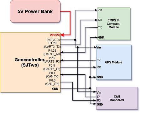
In essence, the Geo-controller is interfaced with a GPS and Compass through UART2 and UART3, respectively. Additionally, the Geo-controller is interfaced with a CAN transceiver in order to receive and send messages from and to other nodes.
Hardware Interface
GPS
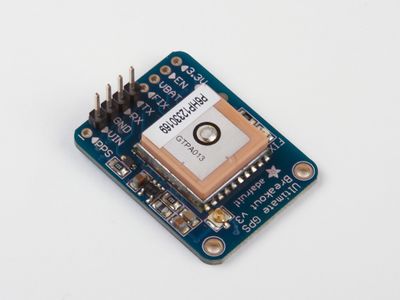
The GPS is responsible for sending GPS NMEA sentences to the Geographical controller to parse and tokenize in order to get the current latitude and longitude in the units, degrees:hours:minutes:seconds. The sentence desired to extract the coordinates is the GPGGA sentence which contains fixed GPS coordinates. The GPS module that we used for this project was the "Ultimate GPS breakout board" from Adafruit. The module was interfaced with the UART2 port of the SJTwo LPC4078 Controller with a baud rate of 9600 and with 1 stop bit.
|
Compass
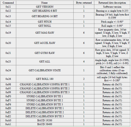
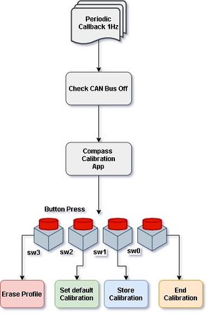
The compass is required to get the current heading of the RC car such that it can send the heading information from the geographical controller to the driver controller to perform destination navigation as part of the driver logic. The compass module purchased for this project was the CMPS14 compass module. This module was interfaced to the (Geographical) SJTwo controller using UART3, a baud rate of 9600, and 2-stop bits. The compass can be operated in two modes, I2C and serial(UART) mode. The compass utilized for the project was set in serial mode using UART2. Its register contents and various commands include receiving the bearing angle in 16 or 8-bit and altering the calibration settings and profiles. Additionally, the cmps14 is tilt-compensated and includes an accelerometer, gyro-meter, and magnetometer.
|
Software Design and Implementation
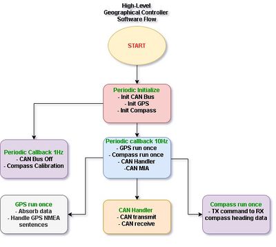
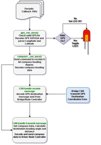
High-level software flow of the geographical controller and periodic callbacks utilized.
GPS NMEA sentence parsing and tokenization
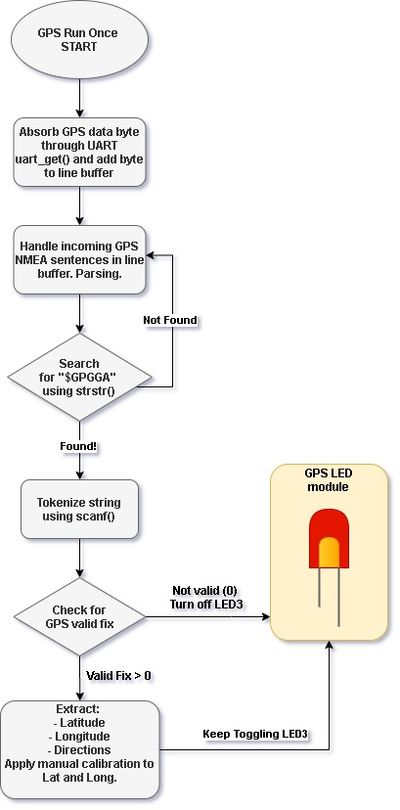
GPS run once is called in the 10Hz periodic callback and is essentially done through obtaining a stream of (GPS NMEA sentence) bytes from the GPS module through UART, storing the stream into a line buffer FIFO. The stream of bytes are then popped to a handle line where the stream of bytes or the GPS strings are then handled and processed by checking for the $GPGGA sentence, in particular, using strstr(). If the string "$GPGGA" is found, then tokenization begins using sscanf() for the relevant information required for extraction: latitude, latitude direction, longitude, longitude direction, and the valid fix value. Before the essential information is extracted, a check must be made using the extracted valid GPS fix value. If the valid GPS fix is greater than 0 (1 or 2 are the only possibilities), then it indicates a valid GPS fix versus, otherwise, if the value is 0, then it is an invalid fix, therefore it should not extract the coordinates. If the latitude direction is South("S" or "s"), then the coordinates extracted will be multiplied by -1. Similarly, if the longitude direction is West("W" or "w"), then the extracted longitude is multiplied by -1. Manual calibration is also implemented by(in our case) adding to the latitude and longitude coordinates. This was done because the readings given to us by the GPS were very poor.
Calculating destination bearing angle
Calculating the destination bearing angle between the current and destination longitude and latitude coordinates was done using the formula as follows...
 Formula: θ = atan2( sin Δλ ⋅ cos φ2 , cos φ1 ⋅ sin φ2 − sin φ1 ⋅ cos φ2 ⋅ cos Δλ )

 where...
 θ  = destination bearing angle
 φ1 = Latitude of origin coordinate
 φ2 = Latitude of destination coordinate
 λ1 = Longitude of origin coordinate
 λ2 = Longitude of destination coordinate
 Δλ = λ2 - λ1
Calculating destination distance
The destination distance between current and destination longitude and latitude coordinates was calculated using the haversine formula.
 a = sin²(Δφ/2) + cos φ1 ⋅ cos φ2 ⋅ sin²(Δλ/2)
 c = 2 ⋅ atan2( √a, √(1−a) )
 d = R ⋅ c

 where...
 R = earth's radius = 6,371,000 meters
 d = distance between current and destination gps coordinates
 c = angular distance in radians
 a = is the square of half the chord length between the points.
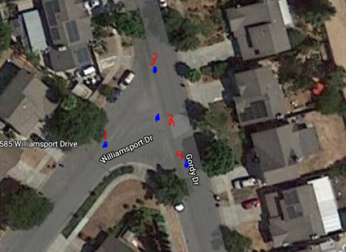
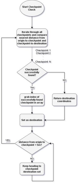
The test are we chose was in a small intersection in a suburban neighborhood. The checkpoints set were set in a manner that would demonstrate that the RC car can navigate through the intersection without cutting through corners through sidewalks as a real would do so. The Longitude and Latitude coordinates were taken from google maps and used to insert into a static const struct array. The algorithm must iterate through the array of checkpoints and determine which point would be navigated towards next based on how close the point is to the car and at the same time how close the point is to the destination.
Technical Challenges
- Issue 1: Probably one of the most difficult challenges to deal with in this project was the inaccuracy of the GPS module. The default readings of this GPS module would be read were not even remotely close to its actual location.
- Solution: Although we did not fully fix this issue, the method that we dealt with the poor accuracy was to implement manual calibration with respect to the actual location of the module using google maps, and either adding or subtracting an offset to the GPS coordinates received from the GPS module.
- Issue 2: Calibration of the compass was another issue. Each time the compass module would boot up, the readings of the heading angle would be off by a considerable amount.
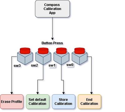
- Solution: The solution to solve this was to send calibration commands to the compass module through button press. Helpful commands to send to the compass was erasing the calibration profile and setting default calibration settings.
- Issue 3: The checkpoints set using google maps for our area used for testing were shifted when doing physical testing with the RC car. This was due to the poor accuracy of the GPS despite our efforts in performing some manual calibration of the GPS.
- Solution: The solution, although not perfect, was to set an offset to the original checkpoints such that the newly shifted coordinates would reflect the checkpoints originally set using google maps.
- Issue 4: Another issue encountered was the failure of connecting to the mobile application in time of the demo.
- Solution: The only solution we had was to hardcode GPS coordinates for the destination instead.
Communication Bridge Controller
note: The bridge and sensor controller are separate in the report to provide clarity of the modules used in each node. In reality, the bridge and sensor nodes are implemented together in one SJTWO controller.
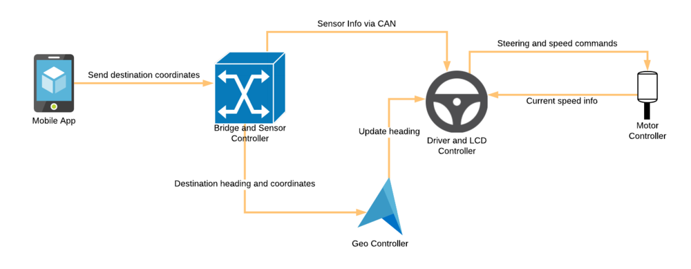
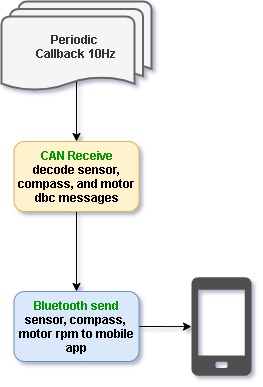
The bridge controller is responsible for receiving and sending data from and to the mobile application of this project. For this project, the bridge and sensor nodes are controlled by one SJTWO microcontroller.There are several ways to make affective communication between SJTWO and mobile application such as Zigbee, WIFI and Bluetooth. Nimble bases its communication with mobile app through HC-05 bluetooth module. The bridge controller is interfaced with a bluetooth module in order to connect to the mobile application. Its main purpose is to receive GPS destination coordinates set by the user of the mobile app and send the destination to the geographical controller to be processed and determine a destination heading for the RC car to navigate to. In addition, the bridge controller may receive debug information such as sensor, compass, motor rpm, and current GPS coordinates to be sent and displayed on the mobile app.
Hardware Design
The HC-05 modules are very clever pieces of hardware, as they translate incoming Bluetooth communication to serial data. So once configured this gives the tinkerer the possibility to achieve serial communication over Bluetooth.
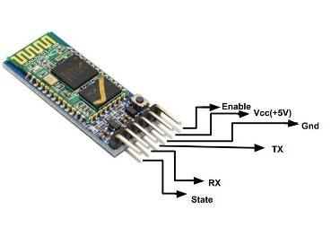
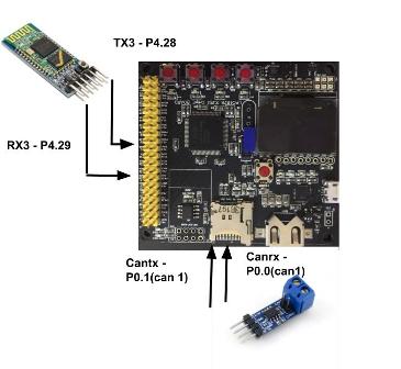
The HC-05 acts transparently, meaning that you just communicate with the serial port it is connected to and the module then sends/receives via Bluetooth. A typical operating voltage of hc-05 is between 4-6V and has nominal range of 100m. The communication was uart based and operates at 115200 baud rate.The ultrasonic sensors and bridge resides on the same controller board. The pin connection description of the module is shown in the figure below. The TX and RX end are connected to P2.48 and P2.49 of SJTWO board which is RX3 and TX3. The same controller also houses 4 sensors and the the communication takes place via can transceiver. Can1 is used to transmit the values to other modules that can further act upon data.
Software Design and Implementation
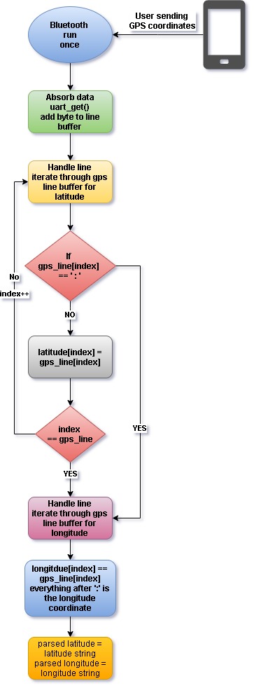
The software for this part was a Bluetooth module for the SJ2 board. The data sent from the mobile application will be parsed and sent to the geographical controller using the dbc encode and send method. Additionally, sensor, compass, and motor messages would be decoded to be received from their respective controllers. This data would then be parsed by python in the main app to send to the(mobile app) front end.
Bluetooth run once
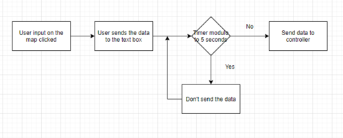
The software design is similar to the GPS run once in terms of absorbing data from UART and adding the bytes to a line buffer. The differences lie in tokenizing the gps_line that is being sent from the mobile app. The data being sent is the GPS latitude and longitude itself which is delimited by a " : ". We can parse the latitude and longitude as well as the directions easily by iterating through the gps line by the length of the coordinates and storing the respective coordinates by checking whether the delimiter, ":" has been detected or not.
Bluetooth send
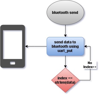
Sending data to the HC-05 module is done by using the uart__put() method provided in the sjtwo-c development environment from Preet.
Technical Challenges
- Issue 1: Bluetooth module - the main problem with this was trying to get the parts to print on Hercules after sending data from the App.
- Solution: This issue was resolved once the stop bits were figured out.
- Issue 2: Data formation - a problem with this was getting the correct way to send data to the Python back end and then parsing the information.
- Solution: This was resolved by making the data sent in a certain way.
Driver Controller & LCD
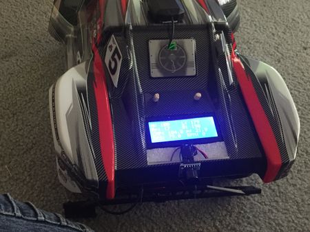
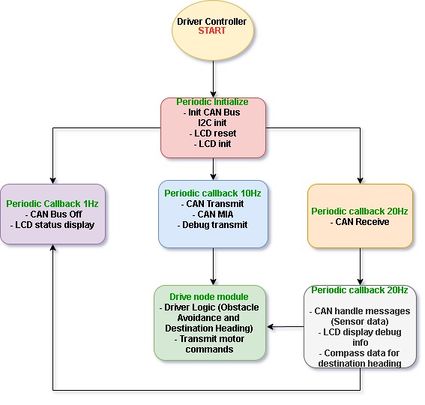
The driver controller is responsible for performing driver logic which will execute both obstacle avoidance and destination navigation. Additionally, an LCD display screen is used as a dashboard to provide the user with meaningful information such as sensor values, GPS destination set, compass bearing degree, distance to the destination, and speed information of the car.
Hardware Design
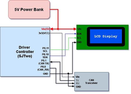
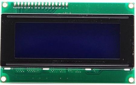
The only hardware that the driver is required to be interfaced with, is the LCD display. The LCD display used for this project is a 20x4 LCD screen and is interfaced using I2C with the aid of an I2C backpack which came with the display.
Hardware Interfacing
LCD
|
Software Design and Implementation
Driver Logic
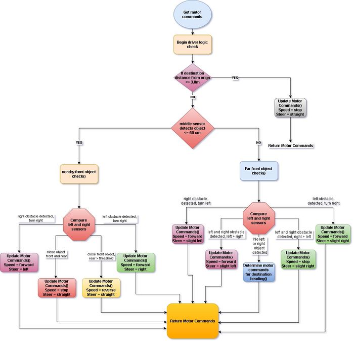
Obstacle Avoidance
Obstacle avoidance is implemented first by setting a comfortable detection threshold range(in cm) for the sensors. These threshold values determine whether an action must be taken if a sensor detects an object equal to or less than the allowed threshold. For example, if the left sensor detects an object that is closer than or equal to a threshold of 30 cm, and if the right and middle sensor do not, then the RC car should steer right to avoid the detected object on the left. If no object is detected by the front three sensors, then the car should resume GPS navigation. When an action is determined, the driver controller sends motor commands(through CAN) to the motor controller to update the speed and/or steering of the RC car.
The code snippet below shows object avoidance for far front objects or when the front sensor does not detect any objects nearby, so the left and right sensor values are compared against each other to determine whether a slight left or slight right turn should be taken when avoiding an object on the left or right.
 static void driver_logic__get_motor_commands_for_far_away_front_object(void) {

 if ((driver_SENSOR_SONAR.SENSOR_SONARS_right <= sensor_threshold_mid) &&
     (driver_SENSOR_SONAR.SENSOR_SONARS_left > sensor_threshold_mid)) {
   driver__update_motor_cmd(MOTOR_STEER_CMD_slight_left, MOTOR_SPEED_CMD_forward);

 } else if ((driver_SENSOR_SONAR.SENSOR_SONARS_left <= sensor_threshold_mid) &&
            (driver_SENSOR_SONAR.SENSOR_SONARS_right > sensor_threshold_mid)) {
   driver__update_motor_cmd(MOTOR_STEER_CMD_slight_right, MOTOR_SPEED_CMD_forward);
                                       .
                                       .
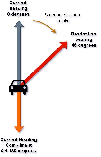
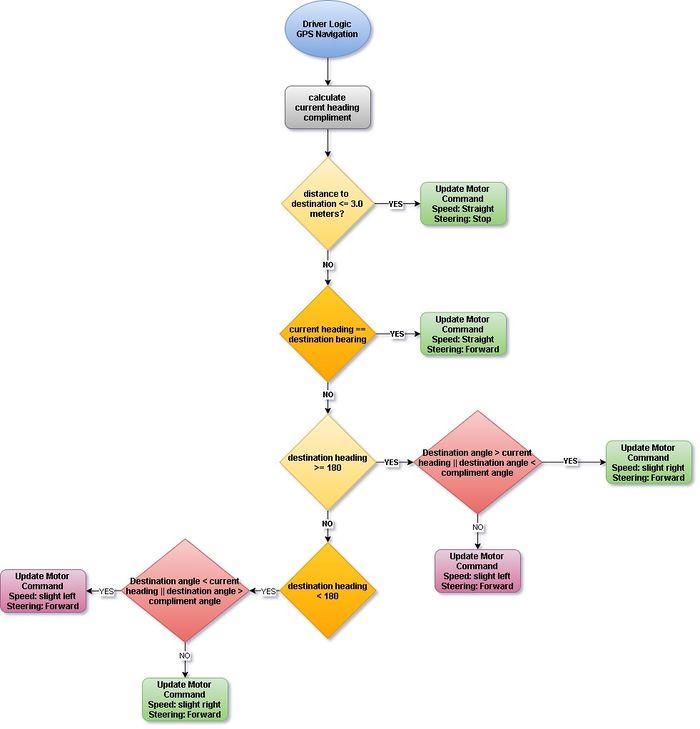
The navigation logic implemented within the driver logic of the driver controller is responsible for having the RC car steer towards the destination. This is done by updating the motor steering commands to turn in the direction such that the current heading of the RC car matches the destination bearing angle that is calculated and sent from the geographical controller. Additionally, the navigation logic should be implemented in such a way that it does not interfere with the obstacle avoidance such that avoiding obstacles on the way to the destination is still the highest priority. Lastly, a complimentary angle to the current heading angle is calculated to help determine whether it is better to steer right or left when comparing the current and destination heading angles.
The code snippet below shows a partial implementation of the GPS navigation in the driver logic. First, if the car is within 3 meters of the destination, then the car will stop as it has arrived at its destination. If not, it will then go on to check the cases when the current heading angle is equal to the destination angle and if so, it should continue straight towards the destination. The inner if() check statements check whether if the current heading is greater than or equal to 180 degrees. If so, it will then compare the current and complimentary heading with the destination heading angle and either turn slight left or slight right if the right conditions are met.
 if (distance_to_destination <= 3.0) {
   driver__update_motor_cmd(MOTOR_STEER_CMD_straight, MOTOR_SPEED_CMD_stop);
 } else {
   if (current_heading == destination_bearing) {
     driver__update_motor_cmd(MOTOR_STEER_CMD_straight, MOTOR_SPEED_CMD_forward);
   } else if (current_heading >= 180) {
     if (destination_bearing > current_heading || destination_bearing < current_heading_compliment) {
       driver__update_motor_cmd(MOTOR_STEER_CMD_slight_right, MOTOR_SPEED_CMD_forward);
     } else if (destination_bearing < current_heading || destination_bearing > current_heading_compliment) {
       driver__update_motor_cmd(MOTOR_STEER_CMD_slight_left, MOTOR_SPEED_CMD_forward);
     }
                                              .
                                              .
LCD Display
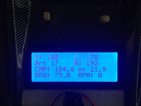
The LCD display for this project displays sensor values, compass heading data, distance to destination, destination bearing angle, and the RPM value. The first and second row of the LCD contains the sensor values, the middle(M), rear(Rr), left(L), and right(R) sensors. The third row displays the compass(CMP)heading and the distance to destination in meters(m). Lastly, the fourth row contains the destination bearing angle(BRG) and the revolutions per minute(RPM) value of the car motor speed.
Initialization
The LCD is first reset to clear the screen of contents on startup of the RC car and then initialized to begin updating information on the display. The LCD is initialized by sending a series of commands before writing characters to the display. Commands to enable interfacing mode to 4-bit mode is done first. The display is then cleared and the cursor is set to autoincrement such that when a character is written to the LCD, the cursor will automatically increment to the next space for the next character to be written. Lastly, the LCD will start at the first row(LINE 1). Additionally, a delay must be added for the commands to successfully be sent to the LCD.
 void LCD__init(void) {

 LCD__command_to_LCD(FOUR_BIT_MODE);

 LCD__command_to_LCD(DISPLAY_AND_CURSOR);

 LCD__command_to_LCD(CLEAR_SCREEN);

 LCD__command_to_LCD(AUTOINCREMENT_CURSOR);

 LCD__command_to_LCD(LINE1);

 delay__ms(5);
 }
Updating the LCD Status
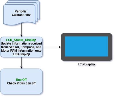
Updating the status of the display was called in the 1Hz periodic callback. The function takes the struct values of each debug information and is put into a buffer to be written onto the LCD display. Before writing each debugging information, for example, the middle and left sensor values, a command must be sent to indicate the row in which the values should be written. This is done for all pieces of debug information.
 void LCD_status__display_on_screen(void) {
 char lcd_buffer[20];
 LCD__command_to_LCD(CLEAR_SCREEN);

 LCD__command_to_LCD(LINE1);
 sprintf(lcd_buffer, "M: %i", lcd_sensor.SENSOR_SONARS_mid);
 LCD__string_to_LCD(lcd_buffer);

 LCD__command_to_LCD(LINE1 + 10);
 sprintf(lcd_buffer, "L: %i", lcd_sensor.SENSOR_SONARS_left);
 LCD__string_to_LCD(lcd_buffer);

 LCD__command_to_LCD(LINE 2 );
 sprintf(lcd_buffer, "Rr: %i", lcd_sensor.SENSOR_IR_rear);
 LCD__string_to_LCD(lcd_buffer);

 LCD__command_to_LCD(LINE 2 + 10);
 sprintf(lcd_buffer, "R: %i", lcd_sensor.SENSOR_SONARS_right);
 LCD__string_to_LCD(lcd_buffer);
               .
               .
               .
|
Technical Challenges
- Issue 1: The first issue with the driver controller was testing obstacle avoidance in a physical test with the RC car. This issue was mostly trial and error when trying to set well-balanced sensor thresholds.
- Solution: Trial-and-error in doing physical tests to see how the RC car reacts and to determine what sensor value threshold would be adequate enough to detect objects far enough such that the RC car has enough time to react.
- Issue 2: Another issue that we faced was updating the LCD display. Since the commands that are required to be sent to the LCD require some delays, updating the LCD in a periodic call in the 10Hz or above would end up resetting the micro-controller.
- Solution: Putting the LCD display update function was put into the 1Hz periodic callback.
- Issue 3: Fitting all information on the LCD display was difficult considering the size limit of the 20x4 LCD.
- Solution: Applying short but meaningful abbreviations to the labels of each debug information onto the display. A better solution would be is to print multiple status screens for different forms of information.
Mobile Application
Software Design
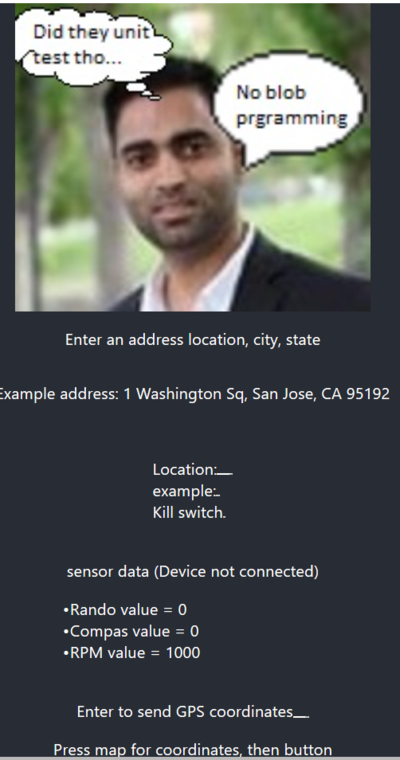
The software's main front end code was written in Javascript while the backend was written in Python flask to send and receive data from the microcontroller to the app. The methods of sending GPS coordinates from the app to the microcontroller was using a location's address or a point and click map from google. To receive the data from the microcontroller, the data had to be sent from the Bluetooth module in a specific way such that python could parse through the data and then separate it into sensor and sensor value. The sent data would be picked up every five seconds so that this would allow for the user to send data without having sockets closing from the code before the data could send.
Technical Challenges
The main technical challenge was learning Javascript without having any prior experience in coding Javascript, but to do this lots of research was done on how to make classes, send data to the backend, and how to make the webpage dynamic in updating information. Another challenge was making the Bluetooth module work with the microcontroller for this class. The difficulties in this were that the Bluetooth module was made for an Arduino so the settings had to be modified so that it could work with other microcontrollers by modifying the Baud rate and stop bits. The last technical challenge was working with a python backend. The reason for this is that there is a method that was needed to get information from the front end that was not familiar to the normal python, instead of GET and POST methods had to be researched to get the data and then printed on the webpage instead of using a simple print function.
Javascript and React-framework: The challenge in this was learning a new language, but to resolve this many youtube videos were watched and forums were read to learn how to program in a new language.
Bluetooth module development: This was difficult because the stop bits had to be played around with until the right one was selected, but after changing the values around the proper setup was made after a while
Flask and python backend: The problems with this were programming in an unconventional python way, instead, it dealt with POST and GET methods to gather front end data and if there were errors then the simple print functions couldn't be used to find the values of variables but they had to be printed onto a second webpage. To fix this, many tries were taken to try and get the data from the front end as well as finding a way to find the data values easier.
Conclusion
Nimble was a great opportunity to learn test-driven design strategies, which helped lower the amount of time troubleshooting issues. It also taught us much about using Git for version control. The project also gave us experience working with embedded systems technologies such as the following:
- Can Bus (Including Bus Master):
- Using the CAN bus to communicate with multiple different devices instead of using SPI and UART, which is something totally new.
- How to debug and understand the CAN message using the BusMaster.
- Modifying the DBC to get different CAN messages, and data that transfer in-between different controller nodes.
- Sensor:
- How to properly initialize the sensor and transfer the creating the driver logic-based from the data of the sensor.
- GPS & Compass:
- NMEA data packets and what to expect for the GPS module. It is also interesting on how to initialize and calibrate the compass and GPS
- Unit Testing:
- We learned the Unity and CMOCK framework, and how to unit-test our code modules which sped up the development of the components of the project. In particular, the GPS and Compass were thought to be the hardest to get working, but with an early start and unit-testing, these modules faced little issues to get working. The only difficulties as mentioned before was the calibration and accuracy.
- We believe that this is by far the most useful and interesting experience that we have encountered this semester. Although we're still not experts on writing flawless unit-tests, it doesn't change the fact of how incredibly revolutionary and useful it was during our project.
- GIT:
- We learned all the basic go GIT and it helps us collaborate on the different modules virtually without physical meeting. (Because of Corona Virus)
Although there were some problems encountered while doing this project, we were able to finish the majority of the basic tasks required of the project. Unfortunately, we were not able to implement the mobile application as a requirement due to some issues encountered with the connectivity of the Bluetooth module which occurred in the last week of the project. Additionally, because of the COVID-19 outbreak, classes had to be conducted through google hangouts for the rest of the semester. The outbreak also made it difficult to meet physically with teammates which made it difficult to not only integrate and test the RC car, but it also reduced involvement in the project of every teammate. Despite these shortcomings of the project, the overall experience was fun and interesting. The class and project helped us learn a TON of new concepts and skills that will prove valuable in the future and industry.
Project Video
Project Source Code
Advice for Future Students
- Advice 1: Always make sure the teammate you choose is responsible since teammate is the most important part of this group project. If any teammate is not responsible, make sure you pursue them and keep track of their progress. Otherwise, you will end up finishing their lack of progress. Also, make sure you get your teammates' contact information, besides slack, like phone or text messages.
- Advice 2: Set an earlier deadline and make sure your teammates finish before the deadline. There should be no tolerance because this project will be more difficult when there is a lack of contribution from team members. If there are no strong leaders within your team, the result of your project will not be great. Also, assign important tasks, like GPS and Mobile application, to someone with the most knowledge and reliability, since those two are by far the most difficult part of the RC car. A rough draft of the mobile application should be highly considered early on. Especially if nobody in your team has experience in mobile app development. It is HIGHLY recommended to refer to the previous semesters' team to get a GOOD LOOK of Preet's expectations .
- Advice 3: Make sure the GPS modules you purchase is over $90 where it is more reliable. DO NOT purchase the GPS our team purchase, where has is shown significant failure. Make sure you guys spend more money on the GPS module as it is a critical component of the project.
- Advice 4: Plan a backup in case something goes wrong. Always make sure you give enough time to polish your final Project. This includes having enough time to make a good enclosure or packaging for the RC car. Additionally, it's good to adapt to a change of situation if needed. In our case, due to the COVID-19 outbreak, group meetings were scheduled over google hangout instead of in-person.
- Advice 5: Overall this is an interesting class project, where you learn a lot. Please take advantage of this project by asking Preet lots of questions. Again, the teammates you choose will be important. DO NOT wait until the second lecture to form your team. Make sure you form your team during the first two weeks of the lecture!
- Advice 6: Make sure everyone in your group shows up in the Preet's Lectures because Preet provided a lot of useful information related to our major and project. Missing one day of lectures can cause 1 week of set back for your project.
- Advice 7: Make sure to read through previous reports before finalizing on the sensors to be used. Buy a few additional sensors as a backup. Make sure you solder the pins with keeping their eventual placement on the RC car in mind. Desoldering the pins on the ultrasonics is a really tedious job, so save yourself some time.
Acknowledgement
- Preet for introducing us to new concepts/technical skills and continuing to teach us innovative practices that would not be taught in the industry.
- ISAs Aakash Chitroda and Vignesh Kumar for being great ISAs in guiding and keeping us on track throughout the semester!
- Previous 243 groups who provided great wiki reports of their projects and have given us advice and tips which helped us with our project.
References
- website used to calculate destination distance(haversine formula) and the destination heading angle:bearing angle and distance link
- Latitude and Longitude Finder lat and long finder
- google maps for setting checkpoints google maps
