Difference between revisions of "F19: Alien Wars"
Proj user9 (talk | contribs) (→Grading Criteria) |
Proj user9 (talk | contribs) (→Conclusion) |
||
| (275 intermediate revisions by the same user not shown) | |||
| Line 1: | Line 1: | ||
| − | == | + | == Alien Wars == |
| − | + | [[File:Cover.png|thumb|750x500px|center|]] | |
== Abstract == | == Abstract == | ||
| Line 10: | Line 10: | ||
missiles or dodge it. The game ends when the player crashes with enemy spaceship. | missiles or dodge it. The game ends when the player crashes with enemy spaceship. | ||
| − | == Objectives & Introduction == | + | == Objectives & Introduction == |
| − | + | ||
| + | === Objectives === | ||
| + | *Write drivers to display game characters and update the display continuously | ||
| + | *Implement game algorithm for movement of player and enemy spaceships in real-time, generate bullets. | ||
| + | *Implement spaceship, health and bullet collision algorithm | ||
| + | *Write drivers to give directions from the input device (joystick) | ||
| + | *Write drivers to transmit control signals wirelessly via Bluetooth | ||
| + | *Write drivers to play game sounds via MP3 encoder | ||
| + | *Use FreeRTOS tasks and understand task priority and synchronization. | ||
| + | |||
| + | === Game User guide === | ||
| + | |||
| + | * Single player arcade game. | ||
| + | * Three levels to reach victory. | ||
| + | * Press switch on the joystick to start. | ||
| + | * Movement of joystick controls the movement of spaceship | ||
| + | * Press switch on joystick will now shoot bullets | ||
| + | * Game advances as the spaceship kills certain enemy spaceships | ||
| + | * The speed of the enemy spaceship increases in the second level | ||
| + | * In the final level, the user spaceship faces the villain, user spaceship has to face the bullets from villain as well. | ||
| + | * User spaceship has to survive the bullets and fire the enemy. After taking few hits, villain dies and its victory! | ||
| + | * Throughout the game when the user spaceship collides with enemy or bullet, its health decreases, the color of the spaceship also changes. The game is over when player health is zero. | ||
=== Team Members & Responsibilities === | === Team Members & Responsibilities === | ||
* Abhinandan Burli | * Abhinandan Burli | ||
| + | ** Developing enemy game algorithm | ||
| + | ** Developing game characters on LED matrix display | ||
| + | ** GPIO driver for LED matrix display | ||
* Joel Samson | * Joel Samson | ||
| − | + | ** Joystick interfacing - ADC driver | |
| + | ** Bluetooth Interfacing - UART driver for transmitter & receiver | ||
| + | ** Game Animation Screens | ||
| + | |||
* Basangouda Patil | * Basangouda Patil | ||
| + | ** Speaker and MP3 encoder interfacing | ||
| + | ** GPIO driver for LED matrix displays | ||
| + | ** Bug fixes and optimizations | ||
== '''Schedule''' == | == '''Schedule''' == | ||
| Line 33: | Line 63: | ||
! scope="row"| 1 | ! scope="row"| 1 | ||
| − | | 10/ | + | | 10/01/2019 |
| | | | ||
* Submission of Project Proposal | * Submission of Project Proposal | ||
| | | | ||
| − | * | + | * Complete |
| | | | ||
| − | * 10/ | + | * 10/07/2019 |
|- | |- | ||
| + | ! scope="row"| 2 | ||
| + | | 10/08/2019 | ||
| + | | | ||
| + | * Alien Wars Project Approved | ||
| + | | | ||
| + | * Complete | ||
| + | | | ||
| + | * 10/14/2019 | ||
| + | |- | ||
| − | ! scope="row"| | + | ! scope="row"| 3 |
| 10/15/2019 | | 10/15/2019 | ||
| | | | ||
| − | * | + | * Create Wiki page for our project |
| − | * Submit plan for upcoming weeks | + | * Submit project plan for upcoming weeks |
| | | | ||
| − | * | + | * Complete |
| + | * Complete | ||
| | | | ||
| − | * 10/ | + | * 10/21/2019 |
|- | |- | ||
| − | ! scope="row"| | + | ! scope="row"| 4 |
| 10/22/2019 | | 10/22/2019 | ||
| | | | ||
| − | * | + | * Research Required Components - LED matrix display, Joystick, Bluetooth module, MP3 encoder |
* Order Parts and Identify Roles | * Order Parts and Identify Roles | ||
| − | |||
| | | | ||
| − | * | + | * Complete |
| + | * Complete | ||
| | | | ||
| − | * | + | * 10/28/2019 |
|- | |- | ||
| − | ! scope="row"| | + | ! scope="row"| 5 |
| 10/29/2019 | | 10/29/2019 | ||
| | | | ||
| − | |||
| + | * Analyze the hardware components - Bluetooth, LED Matrix display, MP3 encoder, joystick module. | ||
| + | * Read datasheets of all the components | ||
| | | | ||
| − | * | + | * Complete |
| + | * Complete | ||
| | | | ||
| − | * | + | * 11/04/2019 |
|- | |- | ||
| − | ! scope="row"| | + | ! scope="row"| 6 |
| − | | 11/ | + | | 11/05/2019 |
| | | | ||
| − | * Develop | + | * Develop basic game design, wiring and GPIO driver for LED matrix display. |
| − | * | + | * Test LED matrix display |
| + | * Print characters for start screen | ||
| | | | ||
| − | * | + | * Complete |
| + | * Complete | ||
| + | * Complete | ||
| | | | ||
| − | * | + | * 11/11/2019 |
|- | |- | ||
| − | ! scope="row"| | + | ! scope="row"| 7 |
| 11/12/2019 | | 11/12/2019 | ||
| − | |||
| − | |||
| | | | ||
| − | * | + | * Display objects on screen, control dynamic movement of player spaceship. |
| + | * Develop UART driver for wireless joystick communication (Bluetooth HC05 module) | ||
| + | | | ||
| + | * Complete | ||
| + | * Complete | ||
| | | | ||
| − | * | + | * 11/17/2019 |
|- | |- | ||
| − | ! scope="row"| | + | ! scope="row"| 8 |
| 11/19/2019 | | 11/19/2019 | ||
| | | | ||
* LED matrix integration with game. | * LED matrix integration with game. | ||
| + | * Develop enemy spaceships game algorithm | ||
| + | * Develop ADC driver for joystick interfacing | ||
| + | * Develop UART driver for MP3 encoder to play game sounds | ||
| | | | ||
| − | * | + | * Complete |
| + | * Complete | ||
| + | * Complete | ||
| + | * Complete | ||
| | | | ||
| − | * | + | *11/26/2019 |
|- | |- | ||
| − | ! scope="row"| | + | ! scope="row"| 9 |
| 11/26/2019 | | 11/26/2019 | ||
| | | | ||
| − | * Joystick Integration with | + | * Joystick Integration with LED matrix display |
| + | * Develop missile collision and player life algorithm | ||
| | | | ||
| − | * | + | * Complete |
| + | * Complete | ||
| | | | ||
| − | * | + | * 12/03/2019 |
|- | |- | ||
| − | + | ||
| − | ! scope="row"| | + | ! scope="row"| 10 |
| − | | 12/ | + | | 12/03/2019 |
| | | | ||
| − | * | + | * Initial game Testing |
| + | * Source code optimization | ||
| | | | ||
| − | * | + | * Complete |
| + | * Complete | ||
| | | | ||
| − | * | + | * 12/09/2019 |
|- | |- | ||
| − | ! scope="row"| | + | ! scope="row"| 11 |
| 12/10/2019 | | 12/10/2019 | ||
| | | | ||
| − | * Integration Testing | + | * Integration Testing |
| + | * Bug Fixes | ||
| | | | ||
| − | * | + | * Complete |
| + | * Complete | ||
| | | | ||
| − | * | + | * 12/16/2019 |
|- | |- | ||
| − | ! scope="row"| | + | ! scope="row"| 12 |
| 12/17/2019 | | 12/17/2019 | ||
| | | | ||
| Line 145: | Line 204: | ||
* Complete wiki report and final demo. | * Complete wiki report and final demo. | ||
| | | | ||
| − | * | + | * Complete |
| + | * Complete | ||
| | | | ||
| − | * | + | * 12/18/2019 |
|- | |- | ||
| Line 191: | Line 251: | ||
| 1 | | 1 | ||
| $9 | | $9 | ||
| + | |- | ||
| + | ! scope="row"| 6 | ||
| + | | MP3 music player (YX5300) | ||
| + | | Amazon | ||
| + | | 1 | ||
| + | | $8 | ||
| + | |- | ||
| + | ! scope="row"| 7 | ||
| + | | 5V,4A Power Adapter | ||
| + | | Amazon | ||
| + | | 1 | ||
| + | | $10 | ||
| + | |- | ||
| + | ! scope="row"| 8 | ||
| + | | DC Female Jack Power Adapter | ||
| + | | Amazon | ||
| + | | 1 | ||
| + | | $5 | ||
| + | |- | ||
| + | ! scope="row"| 9 | ||
| + | | AUX cable | ||
| + | | Amazon | ||
| + | | 1 | ||
| + | | $5 | ||
|- | |- | ||
|- | |- | ||
| Line 196: | Line 280: | ||
== Design & Implementation == | == Design & Implementation == | ||
| − | |||
=== Hardware Design === | === Hardware Design === | ||
| − | + | * We used the following hardware for our project - 3 SJ2 boards, a 32x64 LED matrix display, 2 HC-05 Bluetooth modules, 1 thumb Joystick, YX5300 Mp3 module | |
| + | [[File:AW_block_diagram1.png|thumb|750x500px|center| Alien Wars block diagram]] | ||
| + | |||
| + | === YX5300 mp3 Module === | ||
| + | |||
| + | [[File:Yx5300 board layout.jpg]] | ||
| + | |||
| + | While browsing on amazon looking for a module to play extended sound effects (mp3 and wav files), I came across these modules that looked like they would fit my purpose. | ||
| + | While it is easy to make the board play a sound, the downside is that there is not a huge lot of documentation for the board and the original is in Chinese. A copy of the official documentation I was able to find can be reached through this link. | ||
| + | library can be found at on my code repository. | ||
| + | |||
| + | |||
| + | The yx5300 supports 8khz to 48khz sampling frequency mp3 and wav file formats. The audio files are stored on a micro SD card that plugs into a TF card socket on the back of the board. | ||
| + | |||
| + | The MCU controls the device playback by sending serial commands through a TTL level UART control interface (gnd, vcc, tx, rx). Pins are connected gnd to mcu ground, vcc to 5v power supply, yx5300 tx (transmit) to the designated rx (receive) pin for the library, yx5300 rx to tx. The mcu rx/tx can be hardware serial pins or a software controlled serial port. | ||
| + | Sound is output through a headphone jack to headphones or an external amplifier. The board has a playback indicator led that blinks during playback and is steady otherwise. | ||
| + | The TF card socket on the pcb reverse is for plugging in the micro SD card with mp3/wav files. The micro SD card should be formatted as fat16 or fat32 and songs must be prefixed with a unique 3 digit index number (for example, 001xxx.mp3, 002xxx.mp3, 003xxx.mp3, etc, where xxx is an arbitrary optional name. Songs may also be grouped in folders named ’01’, ’02’, ’03’, etc. An example folder and file structure on the micro SD card might look like: | ||
| + | |||
| + | <pre> | ||
| + | +-+- 01 | ||
| + | | + 001-happy_dance.mp3 | ||
| + | | + 002-o_sole_mio.mp3 | ||
| + | | | ||
| + | +- 02 | ||
| + | | + 003-humpty_dumpty.mp3 | ||
| + | | + 004-incy_wincy_spider.mp3 | ||
| + | | + 005-grand_duke.mp3 | ||
| + | | | ||
| + | +- 03 | ||
| + | + 006-fernando.mp3 | ||
| + | + 007-mamma_mia.mp3 | ||
| + | </pre> | ||
| + | |||
| + | Songs are referenced by folder and by song ‘index’, although it seems that the numeric index is sometimes ignored and the songs played in the order they are stored in the sd card. The documentation is unclear on this and seems to imply both situations. So, even if you plan only one playlist, it is better to keep them in a ’01’ folder and save all the songs to the SD card at the same time. | ||
| + | |||
| + | |||
| + | === HC05 Bluetooth Module === | ||
| + | HC-05 module is an easy to use Bluetooth SPP (Serial Port Protocol) module, designed for wireless serial connection setup. It works on 2.4GHz radio transceiver frequency. It has the footprint as small as 12.7mmx27mm. Using AT commands various factors such as baud rate, auto-pairing, security features can be accessed. | ||
| + | The HC05 module has two modes. AT mode and user mode. In order to enter AT mode the manual switch on the board must be pressed for few seconds. The LED display sequence on the board changes indicating successful entry to AT mode. Once the desired configurations are set, reset the module to come out of AT mode | ||
| + | |||
| + | Hardware Features - | ||
| + | |||
| + | * Typical -80dBm sensitivity | ||
| + | * Low Power 1.8V Operation ,1.8 to 3.6V I/O | ||
| + | * UART interface with programmable baud rate - Default Baud rate: 38400. Supported baud rates:9600,19200,38400,57600,115200,230400,460800 | ||
| + | * Programmable stop and parity bits | ||
| + | * Auto - pairing with last connected device | ||
| + | |||
| + | Pin connections - | ||
| + | |||
| + | [[File:Bluetoothpin.png|350px|thumb|center|2-axis joystick]] | ||
| + | |||
| + | === 2-Axis Thumb Joystick === | ||
| + | The thumb joystick is an analog joystick with a 'press in to select' button. Since it's analog, we used two analog reading pins on our microcontroller to determine X and Y readings. In order to read the select button values we used GPIO pin P2_1. The ADC clock frequency was set at 12Mhz. We used the burst mode to read the ADC values. | ||
| + | |||
| + | Hardware Features - | ||
| + | |||
| + | * Usable with any voltage up to 5V | ||
| + | * 2 analog outputs | ||
| + | * 1 milliamp draw when used with 5V | ||
| + | * On-board button | ||
| + | * High sensitivity | ||
| + | |||
| + | === Joystick Pin Connections === | ||
| + | |||
| + | <center> | ||
| + | {| class="wikitable" | ||
| + | |- | ||
| + | ! scope="col"| Joystick Pin | ||
| + | ! scope="col"| Controller Pin | ||
| + | |- | ||
| + | ! scope="row"| Vcc | ||
| + | | Vin | ||
| + | |- | ||
| + | ! scope="row"| Xout | ||
| + | | P0_25 | ||
| + | |- | ||
| + | ! scope="row"| Yout | ||
| + | | P0_26 | ||
| + | |- | ||
| + | ! scope="row"| SEL | ||
| + | | P2_1 | ||
| + | |- | ||
| + | ! scope="row"| Gnd | ||
| + | | Gnd | ||
| + | |- | ||
| + | |- | ||
| + | |} | ||
| + | </center> | ||
| + | |||
| + | [[File:Thumbpin.png|250px|thumb|center|2-axis joystick]] | ||
| + | |||
| + | === LED Matrix === | ||
| + | A 32x64 RGB LED Matrix Panel is used as a display. It has 32 rows and 64 columns. It is divided into two 16x64 sections. A LED or pixel (which we use in subsequent sections) can be accessed and controlled individually. A decoder is used to access individual row. One row can be selected at a time using A,B,C,D pins. This enables us to select one row in each of the 16X64 sections. Columns are controlled using shift registers, every bit in the shift register controls the corresponding column. On every falling edge of the clock pulse, the values at R1, B1, G1, R2, B2, and G2 pins are stored into the shift register and the register shifts the data by one bit. After this, the data on the shift register is passed onto the individual LED's when both OE and LE pins are set to high. | ||
| + | |||
| + | <center> | ||
| + | <table> | ||
| + | <tr> | ||
| + | <td> | ||
| + | [[File:led_matrix_front.jpg|thumb|400x300px|right| LED Matrix front View]] | ||
| + | </td> | ||
| + | <td> | ||
| + | </td> | ||
| + | <td> | ||
| + | [[File:RGB LED Matrix Panel32x64.jpg|thumb|400x300px|left| LED Matrix rear View]] | ||
| + | </td> | ||
| + | </tr> | ||
| + | </table> | ||
| + | </center> | ||
| + | |||
| + | <center> | ||
| + | <table> | ||
| + | <tr> | ||
| + | <td> | ||
| + | LED matrix pins: | ||
| + | {| class="wikitable" | ||
| + | |- | ||
| + | ! align="center"|S.NO | ||
| + | ! align="center"|RGB LED pins | ||
| + | ! align="center"|SJone GPIO pins | ||
| + | |- | ||
| + | | scope="row" align="center"|1 | ||
| + | | scope="row" align="center"|R1 | ||
| + | | scope="row" align="center"|P2.5 | ||
| + | |- | ||
| + | | scope="row" align="center"|2 | ||
| + | | scope="row" align="center"|G1 | ||
| + | | scope="row" align="center"|P0.1 | ||
| + | |- | ||
| + | | scope="row" align="center"|3 | ||
| + | | scope="row" align="center"|B1 | ||
| + | | scope="row" align="center"|P0.18 | ||
| + | |- | ||
| + | | scope="row" align="center"|4 | ||
| + | | scope="row" align="center"|R2 | ||
| + | | scope="row" align="center"|P0.15 | ||
| + | |- | ||
| + | | scope="row" align="center"|5 | ||
| + | | scope="row" align="center"|G2 | ||
| + | | scope="row" align="center"|P2.9 | ||
| + | |- | ||
| + | | scope="row" align="center"|6 | ||
| + | | scope="row" align="center"|B2 | ||
| + | | scope="row" align="center"|P2.7 | ||
| + | |- | ||
| + | | scope="row" align="center"|7 | ||
| + | | scope="row" align="center"|A | ||
| + | | scope="row" align="center"|P2.4 | ||
| + | |- | ||
| + | | scope="row" align="center"|8 | ||
| + | | scope="row" align="center"|B | ||
| + | | scope="row" align="center"|P0.0 | ||
| + | |- | ||
| + | | scope="row" align="center"|9 | ||
| + | | scope="row" align="center"|C | ||
| + | | scope="row" align="center"|P0.22 | ||
| + | |- | ||
| + | | scope="row" align="center"|10 | ||
| + | | scope="row" align="center"|D | ||
| + | | scope="row" align="center"|P0.17 | ||
| + | |- | ||
| + | | scope="row" align="center"|11 | ||
| + | | scope="row" align="center"|CLK | ||
| + | | scope="row" align="center"|P0.16 | ||
| + | |- | ||
| + | | scope="row" align="center"|12 | ||
| + | | scope="row" align="center"|OE | ||
| + | | scope="row" align="center"|P2.8 | ||
| + | |- | ||
| + | | scope="row" align="center"|13 | ||
| + | | scope="row" align="center"|LAT | ||
| + | | scope="row" align="center"|P2.6 | ||
| + | |- | ||
| + | | scope="row" align="center"|14 | ||
| + | | scope="row" align="center"|VCC | ||
| + | | scope="row" align="center"|3.3V | ||
| + | |- | ||
| + | | scope="row" align="center"|15 | ||
| + | | scope="row" align="center"|GND | ||
| + | | scope="row" align="center"|GND | ||
| + | |- | ||
| + | |} | ||
| + | </td> | ||
| + | <td> | ||
| + | </td> | ||
| + | <td> | ||
| + | [[File:LED_BLOCK_DIAG_AW.png|thumb|700x600px|left| LED Matrix Organisation]] | ||
| + | </td> | ||
| + | </tr> | ||
| + | </table> | ||
| + | </center> | ||
| − | === | + | === Software Design and Implementation === |
| − | |||
| − | == | + | == Start up screen: == |
| − | + | Before the RTOS tasks are scheduled, startup_screen() is called. Animation is displayed until user presses the key to start the game. | |
| − | == | + | ==Led Display and Task List: == |
| − | This | + | There are six different tasks to control the course of the game: |
| + | |||
| + | * Refresh Display Task: This task has the following responsibilities | ||
| + | ** Refreshes the screen every 3 milliseconds(involves clearing the screen and updating with latest values). | ||
| + | ** Draws all the characters periodically every 3 milliseconds. | ||
| + | ** Checks for level up | ||
| + | ** Checks collision(Spaceship to Enemy collision, Spaceship to bullet collision, Bullet to Bullet collision) and updates the flags based on the collision type | ||
| + | |||
| + | * Update Spaceship Task: The task keeps track of the data coming wirelessly from the Bluetooth device connected to the board, and accordingly controls user spaceship position. It is designed support movement for all angles. This task also checks if shoot key is pressed and updates the flag if the key was pressed. | ||
| + | |||
| + | * Fire Task: It reads the shoot flag that has been updated in ‘Update Spaceship Task’ and controls the movement of bullet. This task calls PLAY_BULLET(macro to play respective game sound), if bullet hits an enemy. | ||
| + | |||
| + | * Enemy Task1 and Enemy Task2 : This task has the following responsibilities. | ||
| + | ** Generates enemy characters on the upper and lower half of the display and move them till the end unless there is a collision. If there is a collision then the movement is stopped. | ||
| + | ** These also generate random color and random row position for each of these characters. | ||
| + | ** Manages user spaceship health decrement upon collision. | ||
| + | ** PLAY_COLLISION() Macro call to play sound if there is collision | ||
| + | |||
| + | ==Collision detection: == | ||
| + | There are two collision detection functions: | ||
| + | *Check Collision : This function detects the following collisions | ||
| + | **Bullet to Enemy Collision : The movement of bullet and enemy spaceship is stopped and both are cleared from the screen. Kill count is incremented for level up and respective flags are set. Burst animation is played at the collision spot. | ||
| + | **Spaceship to Enemy Collision : The movement of enemy spaceship is stopped and it is cleared from the screen. Respective flags are set and burst animation is played at the collision spot. | ||
| + | |||
| + | *Villian Collision : This function detects the following collisions | ||
| + | **Bullet to bullet collision : The movement of both the bullets are stopped and both are cleared from the screen. | ||
| + | **Spaceship to villain bullet collision : The movement of bullet is stopped and it is cleared from the screen. Health of the user spaceship is decremented. | ||
| + | |||
| + | === YX5300 MP3 MODULE INTERFACING OVER I2C (SLAVE) === | ||
| + | |||
| + | === Communicating with the module === | ||
| + | |||
| + | Communications is via asynchronous serial rs232 at 9600 bps, 8 data bits, no parity, 1 stop bit, no hardware flow control. Flow control is implemented using a request/response protocol with data packets in the following byte format: | ||
| + | |||
| + | [[File:Frame.png]] | ||
| + | |||
| + | Where the fields have the following meaning: | ||
| + | * Start (0x7e) and end (0xef) mark the start and end of the serial packet. A receiver should synchronize on the start byte and read the packet to the end. | ||
| + | * Version is always 0xff. I assume this is to cater for future changes in the protocol and would allow comms software to adjust dynamically. | ||
| + | * Length is the number of bytes between the start byte and checksum. In this implementation it is always 6 bytes (the lighter colored boxes). | ||
| + | * Cmd (command) in a request message is the control function code and in a response is error/status code. | ||
| + | * Fback (feedback) is set to 1 to receive a request acknowledgement, or 0 for no acknowledgement. | ||
| + | * Datahi and datalo are the high and low bytes of the command modifier or the status/error code. They are set to suit the cmd byte (see the tables below). | ||
| + | * Chkhi and chklo are the checksum high and low bytes. The checksum is optional and can be omitted from requests messages, but a response from the device always includes the checksum field. The checksum is calculated as the two’s complement of the 16-bit sum of the bytes between start and checksum (ie, the same as those counted in length). | ||
| + | |||
| + | Device commands | ||
| + | The interesting elements of the protocol message are the cmd and data fields. | ||
| + | The cmd field allows us to control the module. The official english documentation provides a set of valid command codes and the Chinese documentation provides an additional set of codes. All the commands i have discovered are collated in the table below. Where the data field is required this is noted, otherwise it is set to zero and ignored. | ||
| + | |||
| + | * Next_song 0x01 Play next song. | ||
| + | * Prev_song 0x02 Play previous song. | ||
| + | * Play_with_index 0x03 Play song with index number. Data is the index of the file. | ||
| + | * Volume_up 0x04 Volume increase by one. | ||
| + | * Volume_down 0x05 Volume decrease by one. | ||
| + | * Set_volume 0x06 Set the volume to level specified. Data is the volume level [0..30]. | ||
| + | * Set_equalizer 0x07 Set the equalizer to specified level. Data is [0..5] – 0=normal, 1=pop, 2=rock, 3=jazz, 4=classic or 5=base. | ||
| + | * Sng_cycl_play 0x08 Loop play (repeat) specified track. Data is the track number. | ||
| + | * Sel_dev 0x09 Select file storage device. The only valid choice for data is tf (0x02). | ||
| + | * Sleep_mode 0x0a Chip enters sleep mode. | ||
| + | * Wake_up 0x0b Chip wakes up from sleep mode. | ||
| + | * Reset 0x0c Chip reset. | ||
| + | * Play 0x0d Playback restart. | ||
| + | * Pause 0x0e Pause playback. | ||
| + | * Play_folder_file 0x0f Play the file with the specified folder and index number | ||
| + | * Stop_play 0x16 Stop playback. | ||
| + | * Folder_cycle 0x17 Loop playback within specified folder. Data is the folder index. | ||
| + | * Shuffle_play 0x18 Playback shuffle mode. Data is 0 to enable, 1 to disable. | ||
| + | * Set_sngl_cycl 0x19 Set loop play (repeat) on/off for current file. Data is 0 to enable, 1 to disable. | ||
| + | * Set_dac 0x1a Dac on/off control (mute sound). Data is 0 to enable dac, 1 to disable dac (mute). | ||
| + | * Play_w_vol 0x22 Play track at the specified volume. Data hi byte is the track index, low byte is the volume level [0..30]. | ||
| + | * Shuffle_folder 0x28 Playback shuffle mode for folder specified. Data high byte is the folder index. | ||
| + | |||
| + | <pre> | ||
| + | Int main(void) { | ||
| + | |||
| + | i2c_data = 0; | ||
| + | |||
| + | // uart interface to the mp3 module | ||
| + | uart3_init(); | ||
| + | |||
| + | // i2c interface to receive the commands from the display board | ||
| + | i2c2_init(); | ||
| + | |||
| + | // function prototype bool senddatatomp3(char cmd, uint8_t msb, uint8_t lsb); | ||
| + | //set received to 0, so that after we send data we wait for an response and only then go ahead with the next instruction | ||
| + | received = 0; | ||
| + | senddatatomp3(0x09, 0x00, 0x02); | ||
| + | while (received != 1) | ||
| + | ; | ||
| + | |||
| + | // stop playback | ||
| + | received = 0; | ||
| + | senddatatomp3(0x16, 0x00, 0x00); | ||
| + | while (received != 1) | ||
| + | ; | ||
| + | |||
| + | while (1) { | ||
| + | |||
| + | if (i2c_data == 1) { | ||
| + | |||
| + | received = 0; | ||
| + | senddatatomp3(0x08, 0x00, 0x01); | ||
| + | |||
| + | i2c_data = 0; | ||
| + | } else if (i2c_data == 2) { | ||
| + | |||
| + | received = 0; | ||
| + | senddatatomp3(0x0f, 0x01, 0x02); | ||
| + | while (received != 1) | ||
| + | ; | ||
| + | i2c_data = 0; | ||
| + | } else if (i2c_data == 3) { | ||
| + | |||
| + | received = 0; | ||
| + | senddatatomp3(0x0f, 0x01, 0x03); | ||
| + | while (received != 1) | ||
| + | ; | ||
| + | i2c_data = 0; | ||
| + | } else if (i2c_data == 4) { | ||
| + | |||
| + | received = 0; | ||
| + | senddatatomp3(0x0f, 0x01, 0x04); | ||
| + | while (received != 1) | ||
| + | ; | ||
| + | i2c_data = 0; | ||
| + | } | ||
| + | } | ||
| + | </pre> | ||
| + | |||
| + | |||
| + | |||
| + | ===== Bluetooth Implementation (Master & Slave) ===== | ||
| + | Two HC05 Bluetooth modules were used. One was configured as the master using AT commands and the second module as slave. The baud rate for communication was set at 38400. The Master Bluetooth module was interfaced to the player joystick SJ2 board. The slave Bluetooth was interfaced to the main SJ2 board connected to the LED Matrix display. | ||
| + | UART3 was used (Tx and Rx) for communication between the micro controller and HC05 Bluetooth module. On the transmitter side based on the analog joystick input, the enum value corresponding to that particular direction is sent. Based on the value received from the transmitter, decoding was done at the receiver driver and control value was sent to Update Spaceship task for further processing. | ||
| + | |||
| + | [[File:HC05.png|350px|thumb|center|Bluetooth Module]] | ||
| + | |||
| + | '''UART3 initialization steps (Master & Slave)-''' | ||
| + | <pre> | ||
| + | void uart__init_alien_uart3(lpc_peripheral_e uart, uint32_t peripheral_clock, uint32_t baud_rate) | ||
| + | { | ||
| + | |||
| + | Turn ON UART3 peripheral; | ||
| + | Set Pin directions; | ||
| + | Set Pin functions; | ||
| + | set Baud Rate as 38400; | ||
| + | |||
| + | } | ||
| + | </pre> | ||
| + | |||
| + | '''Decoding at receiver node (setting the appropriate enum values)-''' | ||
| + | <pre> | ||
| + | void set_joystick_control_signal(void) { | ||
| + | |||
| + | if (received_data == 1) | ||
| + | joystick_control_signal = down; | ||
| + | else if (received_data == 2) | ||
| + | joystick_control_signal = up; | ||
| + | else if (received_data == 3) | ||
| + | joystick_control_signal = left; | ||
| + | else if (received_data == 4) | ||
| + | joystick_control_signal = right; | ||
| + | else if (received_data == 5) | ||
| + | joystick_control_signal = right_up_diagonal; | ||
| + | else if (received_data == 6) | ||
| + | joystick_control_signal = right_down_diagonal; | ||
| + | else if (received_data == 7) | ||
| + | joystick_control_signal = left_up_diagonal; | ||
| + | else if (received_data == 8) | ||
| + | joystick_control_signal = left_down_diagonal; | ||
| + | else if (received_data == 9) | ||
| + | joystick_control_signal = bullet; | ||
| + | else | ||
| + | joystick_control_signal = center; | ||
| + | } | ||
| + | </pre> | ||
| + | |||
| + | ===== Thumb Joystick - SJTwo Board interface ===== | ||
| + | The thumb joystick communicates with LPC408x controller via two ADC pins. The joystick provides two outputs: X-axis and Y-axis. The X-axis output (joystick) was connected to pin P0.25 (ADC2) and Y-axis output (joystick) to pin P0.26 (ADC3) of the micro controller. | ||
| + | For player spaceship bullet firing the thumb joystick had a built-in button that was used. | ||
| + | Based on the input readings a threshold level was defined. The corresponding enum was sent via Bluetooth to the receiver controller. | ||
| + | |||
| + | [[File:Thumbjoystick.png|350px|thumb|center|2-axis joystick]] | ||
| + | |||
| + | '''ADC initialization steps -''' | ||
| + | <pre> | ||
| + | void adc__initialize_alien(void) | ||
| + | { | ||
| + | |||
| + | Turn ON ADC peripheral; | ||
| + | make ADC operational; | ||
| + | set ADC clock; | ||
| + | Set Pin functions; | ||
| + | select ADC channels; | ||
| + | start burst mode; | ||
| + | |||
| + | } | ||
| + | </pre> | ||
| + | |||
| + | '''Threshold range for different joystick movements -''' | ||
| + | <pre> | ||
| + | if (bullet_flag == true) { | ||
| + | data = 9; | ||
| + | bullet_flag = false; | ||
| + | } else if (missile_flag == true) { | ||
| + | data = 10; | ||
| + | missile_flag = false; | ||
| + | } else if ((value_x > 150 && value_x < 230) && (value_y > 150 && value_y < 230)) | ||
| + | data = 0; // center | ||
| + | else if ((value_x < 150) && (value_y > 150 && value_y < 230)) | ||
| + | data = 3; // left | ||
| + | else if ((value_x > 240) && (value_y > 150 && value_y < 230)) | ||
| + | data = 4; // right | ||
| + | else if ((value_x > 150 && value_x < 230) && (value_y < 150)) | ||
| + | data = 1; // down | ||
| + | else if ((value_x > 150 && value_x < 230) && (value_y > 240)) | ||
| + | data = 2; // up | ||
| + | else if ((value_x > 320) && (value_y > 320)) | ||
| + | data = 5; // right up diagonal | ||
| + | else if ((value_x > 310) && (value_y < 50)) | ||
| + | data = 6; // right down diagonal | ||
| + | else if ((value_x < 100) && (value_y > 290)) | ||
| + | data = 7; // left up diagonal | ||
| + | else if ((value_x < 50) && (value_y < 50)) | ||
| + | data = 8; // left down diagonal | ||
| + | </pre> | ||
== Testing & Technical Challenges == | == Testing & Technical Challenges == | ||
| − | + | This section includes information about testing and the technical challenges we faced while developing this project | |
| − | |||
| − | + | * Technical Challenges | |
| + | '''Flickering of data -''' | ||
| + | Finding a good refresh rate was crucial for the display. The screen ended up flickering for few refresh rates. The task design had to be curated and the refresh rate had to be reevaluated to mitigate flickering. | ||
| + | Also, initially when we started with the project and were interfacing the LED matrix display, we were having issues of random pixels being lit. We referred to online sources and GitHub links of previous projects to see what we were doing wrong. We later changed our initializing sequence and it started working fine and all the issues disappeared. | ||
| − | + | '''SD card formatting and file structure -''' | |
| − | + | ||
| + | Songs are referenced by folder and by song ‘index’, although it seems that the numeric index is sometimes ignored and the songs played in the order they are stored in the SD card. The documentation is unclear on this and seems to imply both situations. So, even if you plan only one playlist, it is better to keep them in a ’01’ folder and save all the songs to the SD card at the same time. | ||
| + | |||
| + | '''Exhausting UART peripherals -''' | ||
| + | |||
| + | We initially planned of interfacing the communication from the display board to the sound board over uart peripheral, as the project went on and since the master board has a bluetooth module to receive data from the joystick which is interfaced over uart too. We exhausted the uart peripherals on the sj two board, as the uart2 and uart4 were not getting iniitialized for some reason. Hence we had to change the interfacing protocol to i2c, where the display was the master and the sound board was the slave. The slave board was already using uart3, we had planned of using tx for communicating with the mp3 module and rx for receiving the commands from the display board. | ||
| + | Finding game sounds to suit our game took a while, as we were looking for free sounds and many websites were selling it for price. | ||
== Conclusion == | == Conclusion == | ||
| − | + | Working on this project has helped us to gain hands-on experience in working with real time systems. We implemented various concepts that we learned in our class. We developed ADC, UART, GPIO drivers on ARM based microcontroller. Working with FreeRTOS tasks we understood the importance of various factors such as semaphores, task priority, task delay. Even though we faced many challenges working hard to solve them was truly rewarding. Apart from technical knowledge we learned other skills such as teamwork, using GIT etc. We are thankful to professor Preet for putting up this amazing class and teaching us skills relevant to current industry. | |
| − | === Project | + | === Project Screenshots === |
| − | + | [[File:screen4.jpeg|thumb|250x250px|center|]] | |
| + | [[File:screen6.jpeg|thumb|250x250px|center|]] | ||
| + | [[File:screen7.jpeg|thumb|250x250px|center|]] | ||
=== Project Source Code === | === Project Source Code === | ||
| − | * [https:// | + | * [https://github.com/joelsam2/alien-wars Project Git link] |
| + | |||
| + | === Project Video === | ||
| + | * [https://www.youtube.com/watch?v=0Dh1qozdMS4] | ||
== References == | == References == | ||
=== Acknowledgement === | === Acknowledgement === | ||
| − | + | We would like to thank our professor Preetpal Kang for putting together this class. It was indeed a great privilege and learning experience to be a part of this class. Big shout-out to all of our classmates, for contributing to Slack discussions. Special thanks to the ISA team for their valuable advice and constructive feedback | |
=== References Used === | === References Used === | ||
| − | + | [1] [https://www.teachmemicro.com/hc-05-bluetooth-command-list/ Bluetooth AT commands] | |
| + | |||
| + | [2] [https://arduinoplusplus.wordpress.com/2018/07/23/yx5300-serial-mp3-player-catalex-module/ MP3 commands] | ||
| − | = | + | [3] [https://pan.baidu.com/s/1hqilpB2#list/path=%2F MP3 module datasheet] |
| − | |||
Latest revision as of 06:14, 13 February 2020
Contents
Alien Wars
Abstract
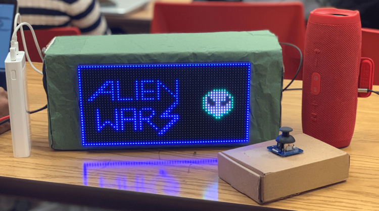
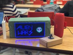
Alien wars is a single player combat game, with increasing levels of difficulty. Each level has a has target number of enemy spaceships to be destroyed, before the ultimate villain ‘the alien king’ appears. Once the ultimate villain is killed the player proceeds to next level. The speed of the enemy spaceships approaching the player will increase with the increasing levels. The player can choose to either shoot the enemy spaceship using missiles or dodge it. The game ends when the player crashes with enemy spaceship.
Objectives & Introduction
Objectives
- Write drivers to display game characters and update the display continuously
- Implement game algorithm for movement of player and enemy spaceships in real-time, generate bullets.
- Implement spaceship, health and bullet collision algorithm
- Write drivers to give directions from the input device (joystick)
- Write drivers to transmit control signals wirelessly via Bluetooth
- Write drivers to play game sounds via MP3 encoder
- Use FreeRTOS tasks and understand task priority and synchronization.
Game User guide
- Single player arcade game.
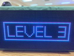
- Three levels to reach victory.
- Press switch on the joystick to start.
- Movement of joystick controls the movement of spaceship
- Press switch on joystick will now shoot bullets
- Game advances as the spaceship kills certain enemy spaceships
- The speed of the enemy spaceship increases in the second level
- In the final level, the user spaceship faces the villain, user spaceship has to face the bullets from villain as well.
- User spaceship has to survive the bullets and fire the enemy. After taking few hits, villain dies and its victory!
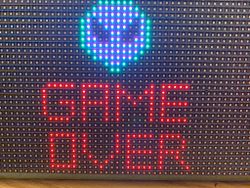
- Throughout the game when the user spaceship collides with enemy or bullet, its health decreases, the color of the spaceship also changes. The game is over when player health is zero.
Team Members & Responsibilities
- Abhinandan Burli
- Developing enemy game algorithm
- Developing game characters on LED matrix display
- GPIO driver for LED matrix display
- Joel Samson
- Joystick interfacing - ADC driver
- Bluetooth Interfacing - UART driver for transmitter & receiver
- Game Animation Screens
- Basangouda Patil
- Speaker and MP3 encoder interfacing
- GPIO driver for LED matrix displays
- Bug fixes and optimizations
Schedule
| Week# | Date | Task | Status | Actual Completion Date |
|---|---|---|---|---|
| 1 | 10/01/2019 |
|
|
|
| 2 | 10/08/2019 |
|
|
|
| 3 | 10/15/2019 |
|
|
|
| 4 | 10/22/2019 |
|
|
|
| 5 | 10/29/2019 |
|
|
|
| 6 | 11/05/2019 |
|
|
|
| 7 | 11/12/2019 |
|
|
|
| 8 | 11/19/2019 |
|
|
|
| 9 | 11/26/2019 |
|
|
|
| 10 | 12/03/2019 |
|
|
|
| 11 | 12/10/2019 |
|
|
|
| 12 | 12/17/2019 |
|
|
|
Parts List & Cost
| Item# | Part Desciption | Vendor | Qty | Cost |
|---|---|---|---|---|
| 1 | SJTwo Boards | From Preet | 3 | $150.00 |
| 2 | 32x64 RGB LED Matrix | Adafruit | 1 | $92.00 |
| 3 | Wiring Components and Cable | Amazon | 1 | $20 |
| 4 | HC05 Bluetooth module | Amazon | 2 | $35 |
| 5 | Adafruit Analog 2-axis thumb Joystick | Adafruit | 1 | $9 |
| 6 | MP3 music player (YX5300) | Amazon | 1 | $8 |
| 7 | 5V,4A Power Adapter | Amazon | 1 | $10 |
| 8 | DC Female Jack Power Adapter | Amazon | 1 | $5 |
| 9 | AUX cable | Amazon | 1 | $5 |
Design & Implementation
Hardware Design
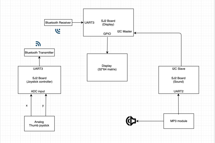
- We used the following hardware for our project - 3 SJ2 boards, a 32x64 LED matrix display, 2 HC-05 Bluetooth modules, 1 thumb Joystick, YX5300 Mp3 module
YX5300 mp3 Module
While browsing on amazon looking for a module to play extended sound effects (mp3 and wav files), I came across these modules that looked like they would fit my purpose. While it is easy to make the board play a sound, the downside is that there is not a huge lot of documentation for the board and the original is in Chinese. A copy of the official documentation I was able to find can be reached through this link. library can be found at on my code repository.
The yx5300 supports 8khz to 48khz sampling frequency mp3 and wav file formats. The audio files are stored on a micro SD card that plugs into a TF card socket on the back of the board.
The MCU controls the device playback by sending serial commands through a TTL level UART control interface (gnd, vcc, tx, rx). Pins are connected gnd to mcu ground, vcc to 5v power supply, yx5300 tx (transmit) to the designated rx (receive) pin for the library, yx5300 rx to tx. The mcu rx/tx can be hardware serial pins or a software controlled serial port. Sound is output through a headphone jack to headphones or an external amplifier. The board has a playback indicator led that blinks during playback and is steady otherwise. The TF card socket on the pcb reverse is for plugging in the micro SD card with mp3/wav files. The micro SD card should be formatted as fat16 or fat32 and songs must be prefixed with a unique 3 digit index number (for example, 001xxx.mp3, 002xxx.mp3, 003xxx.mp3, etc, where xxx is an arbitrary optional name. Songs may also be grouped in folders named ’01’, ’02’, ’03’, etc. An example folder and file structure on the micro SD card might look like:
+-+- 01
  | + 001-happy_dance.mp3
  | + 002-o_sole_mio.mp3
  |
  +- 02
  | + 003-humpty_dumpty.mp3
  | + 004-incy_wincy_spider.mp3
  | + 005-grand_duke.mp3
  |
  +- 03
    + 006-fernando.mp3
    + 007-mamma_mia.mp3
Songs are referenced by folder and by song ‘index’, although it seems that the numeric index is sometimes ignored and the songs played in the order they are stored in the sd card. The documentation is unclear on this and seems to imply both situations. So, even if you plan only one playlist, it is better to keep them in a ’01’ folder and save all the songs to the SD card at the same time.
HC05 Bluetooth Module
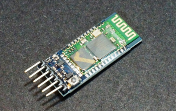
HC-05 module is an easy to use Bluetooth SPP (Serial Port Protocol) module, designed for wireless serial connection setup. It works on 2.4GHz radio transceiver frequency. It has the footprint as small as 12.7mmx27mm. Using AT commands various factors such as baud rate, auto-pairing, security features can be accessed. The HC05 module has two modes. AT mode and user mode. In order to enter AT mode the manual switch on the board must be pressed for few seconds. The LED display sequence on the board changes indicating successful entry to AT mode. Once the desired configurations are set, reset the module to come out of AT mode
Hardware Features -
- Typical -80dBm sensitivity
- Low Power 1.8V Operation ,1.8 to 3.6V I/O
- UART interface with programmable baud rate - Default Baud rate: 38400. Supported baud rates:9600,19200,38400,57600,115200,230400,460800
- Programmable stop and parity bits
- Auto - pairing with last connected device
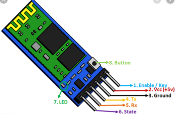
Pin connections -
2-Axis Thumb Joystick
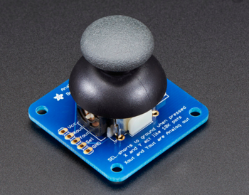
The thumb joystick is an analog joystick with a 'press in to select' button. Since it's analog, we used two analog reading pins on our microcontroller to determine X and Y readings. In order to read the select button values we used GPIO pin P2_1. The ADC clock frequency was set at 12Mhz. We used the burst mode to read the ADC values.
Hardware Features -
- Usable with any voltage up to 5V
- 2 analog outputs
- 1 milliamp draw when used with 5V
- On-board button
- High sensitivity
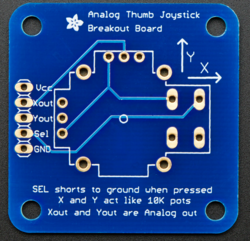
Joystick Pin Connections
| Joystick Pin | Controller Pin |
|---|---|
| Vcc | Vin |
| Xout | P0_25 |
| Yout | P0_26 |
| SEL | P2_1 |
| Gnd | Gnd |
LED Matrix
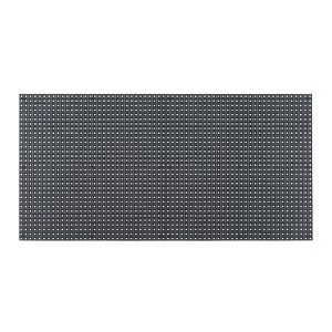
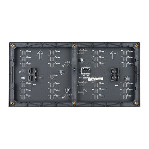
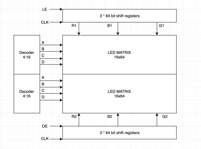
A 32x64 RGB LED Matrix Panel is used as a display. It has 32 rows and 64 columns. It is divided into two 16x64 sections. A LED or pixel (which we use in subsequent sections) can be accessed and controlled individually. A decoder is used to access individual row. One row can be selected at a time using A,B,C,D pins. This enables us to select one row in each of the 16X64 sections. Columns are controlled using shift registers, every bit in the shift register controls the corresponding column. On every falling edge of the clock pulse, the values at R1, B1, G1, R2, B2, and G2 pins are stored into the shift register and the register shifts the data by one bit. After this, the data on the shift register is passed onto the individual LED's when both OE and LE pins are set to high.
|
LED matrix pins:
|
Software Design and Implementation
Start up screen:
Before the RTOS tasks are scheduled, startup_screen() is called. Animation is displayed until user presses the key to start the game.
Led Display and Task List:
There are six different tasks to control the course of the game:
- Refresh Display Task: This task has the following responsibilities
- Refreshes the screen every 3 milliseconds(involves clearing the screen and updating with latest values).
- Draws all the characters periodically every 3 milliseconds.
- Checks for level up
- Checks collision(Spaceship to Enemy collision, Spaceship to bullet collision, Bullet to Bullet collision) and updates the flags based on the collision type
- Update Spaceship Task: The task keeps track of the data coming wirelessly from the Bluetooth device connected to the board, and accordingly controls user spaceship position. It is designed support movement for all angles. This task also checks if shoot key is pressed and updates the flag if the key was pressed.
- Fire Task: It reads the shoot flag that has been updated in ‘Update Spaceship Task’ and controls the movement of bullet. This task calls PLAY_BULLET(macro to play respective game sound), if bullet hits an enemy.
- Enemy Task1 and Enemy Task2 : This task has the following responsibilities.
- Generates enemy characters on the upper and lower half of the display and move them till the end unless there is a collision. If there is a collision then the movement is stopped.
- These also generate random color and random row position for each of these characters.
- Manages user spaceship health decrement upon collision.
- PLAY_COLLISION() Macro call to play sound if there is collision
Collision detection:
There are two collision detection functions:
- Check Collision : This function detects the following collisions
- Bullet to Enemy Collision : The movement of bullet and enemy spaceship is stopped and both are cleared from the screen. Kill count is incremented for level up and respective flags are set. Burst animation is played at the collision spot.
- Spaceship to Enemy Collision : The movement of enemy spaceship is stopped and it is cleared from the screen. Respective flags are set and burst animation is played at the collision spot.
- Villian Collision : This function detects the following collisions
- Bullet to bullet collision : The movement of both the bullets are stopped and both are cleared from the screen.
- Spaceship to villain bullet collision : The movement of bullet is stopped and it is cleared from the screen. Health of the user spaceship is decremented.
YX5300 MP3 MODULE INTERFACING OVER I2C (SLAVE)
Communicating with the module
Communications is via asynchronous serial rs232 at 9600 bps, 8 data bits, no parity, 1 stop bit, no hardware flow control. Flow control is implemented using a request/response protocol with data packets in the following byte format:
Where the fields have the following meaning:
- Start (0x7e) and end (0xef) mark the start and end of the serial packet. A receiver should synchronize on the start byte and read the packet to the end.
- Version is always 0xff. I assume this is to cater for future changes in the protocol and would allow comms software to adjust dynamically.
- Length is the number of bytes between the start byte and checksum. In this implementation it is always 6 bytes (the lighter colored boxes).
- Cmd (command) in a request message is the control function code and in a response is error/status code.
- Fback (feedback) is set to 1 to receive a request acknowledgement, or 0 for no acknowledgement.
- Datahi and datalo are the high and low bytes of the command modifier or the status/error code. They are set to suit the cmd byte (see the tables below).
- Chkhi and chklo are the checksum high and low bytes. The checksum is optional and can be omitted from requests messages, but a response from the device always includes the checksum field. The checksum is calculated as the two’s complement of the 16-bit sum of the bytes between start and checksum (ie, the same as those counted in length).
Device commands The interesting elements of the protocol message are the cmd and data fields. The cmd field allows us to control the module. The official english documentation provides a set of valid command codes and the Chinese documentation provides an additional set of codes. All the commands i have discovered are collated in the table below. Where the data field is required this is noted, otherwise it is set to zero and ignored.
- Next_song 0x01 Play next song.
- Prev_song 0x02 Play previous song.
- Play_with_index 0x03 Play song with index number. Data is the index of the file.
- Volume_up 0x04 Volume increase by one.
- Volume_down 0x05 Volume decrease by one.
- Set_volume 0x06 Set the volume to level specified. Data is the volume level [0..30].
- Set_equalizer 0x07 Set the equalizer to specified level. Data is [0..5] – 0=normal, 1=pop, 2=rock, 3=jazz, 4=classic or 5=base.
- Sng_cycl_play 0x08 Loop play (repeat) specified track. Data is the track number.
- Sel_dev 0x09 Select file storage device. The only valid choice for data is tf (0x02).
- Sleep_mode 0x0a Chip enters sleep mode.
- Wake_up 0x0b Chip wakes up from sleep mode.
- Reset 0x0c Chip reset.
- Play 0x0d Playback restart.
- Pause 0x0e Pause playback.
- Play_folder_file 0x0f Play the file with the specified folder and index number
- Stop_play 0x16 Stop playback.
- Folder_cycle 0x17 Loop playback within specified folder. Data is the folder index.
- Shuffle_play 0x18 Playback shuffle mode. Data is 0 to enable, 1 to disable.
- Set_sngl_cycl 0x19 Set loop play (repeat) on/off for current file. Data is 0 to enable, 1 to disable.
- Set_dac 0x1a Dac on/off control (mute sound). Data is 0 to enable dac, 1 to disable dac (mute).
- Play_w_vol 0x22 Play track at the specified volume. Data hi byte is the track index, low byte is the volume level [0..30].
- Shuffle_folder 0x28 Playback shuffle mode for folder specified. Data high byte is the folder index.
Int main(void) {
i2c_data = 0;
// uart interface to the mp3 module
uart3_init();
// i2c interface to receive the commands from the display board
i2c2_init();
// function prototype bool senddatatomp3(char cmd, uint8_t msb, uint8_t lsb);
//set received to 0, so that after we send data we wait for an response and only then go ahead with the next instruction
received = 0;
senddatatomp3(0x09, 0x00, 0x02);
while (received != 1)
;
// stop playback
received = 0;
senddatatomp3(0x16, 0x00, 0x00);
while (received != 1)
;
while (1) {
if (i2c_data == 1) {
received = 0;
senddatatomp3(0x08, 0x00, 0x01);
i2c_data = 0;
} else if (i2c_data == 2) {
received = 0;
senddatatomp3(0x0f, 0x01, 0x02);
while (received != 1)
;
i2c_data = 0;
} else if (i2c_data == 3) {
received = 0;
senddatatomp3(0x0f, 0x01, 0x03);
while (received != 1)
;
i2c_data = 0;
} else if (i2c_data == 4) {
received = 0;
senddatatomp3(0x0f, 0x01, 0x04);
while (received != 1)
;
i2c_data = 0;
}
}
Bluetooth Implementation (Master & Slave)
Two HC05 Bluetooth modules were used. One was configured as the master using AT commands and the second module as slave. The baud rate for communication was set at 38400. The Master Bluetooth module was interfaced to the player joystick SJ2 board. The slave Bluetooth was interfaced to the main SJ2 board connected to the LED Matrix display. UART3 was used (Tx and Rx) for communication between the micro controller and HC05 Bluetooth module. On the transmitter side based on the analog joystick input, the enum value corresponding to that particular direction is sent. Based on the value received from the transmitter, decoding was done at the receiver driver and control value was sent to Update Spaceship task for further processing.
UART3 initialization steps (Master & Slave)-
void uart__init_alien_uart3(lpc_peripheral_e uart, uint32_t peripheral_clock, uint32_t baud_rate)
{

   Turn ON UART3 peripheral;
   Set Pin directions;
   Set Pin functions;
   set Baud Rate as 38400;

}
Decoding at receiver node (setting the appropriate enum values)-
void set_joystick_control_signal(void) {

  if (received_data == 1)
    joystick_control_signal = down;
  else if (received_data == 2)
    joystick_control_signal = up;
  else if (received_data == 3)
    joystick_control_signal = left;
  else if (received_data == 4)
    joystick_control_signal = right;
  else if (received_data == 5)
    joystick_control_signal = right_up_diagonal;
  else if (received_data == 6)
    joystick_control_signal = right_down_diagonal;
  else if (received_data == 7)
    joystick_control_signal = left_up_diagonal;
  else if (received_data == 8)
    joystick_control_signal = left_down_diagonal;
  else if (received_data == 9)
    joystick_control_signal = bullet;
  else
    joystick_control_signal = center;
}
Thumb Joystick - SJTwo Board interface
The thumb joystick communicates with LPC408x controller via two ADC pins. The joystick provides two outputs: X-axis and Y-axis. The X-axis output (joystick) was connected to pin P0.25 (ADC2) and Y-axis output (joystick) to pin P0.26 (ADC3) of the micro controller. For player spaceship bullet firing the thumb joystick had a built-in button that was used. Based on the input readings a threshold level was defined. The corresponding enum was sent via Bluetooth to the receiver controller.
ADC initialization steps -
void adc__initialize_alien(void)
{

   Turn ON ADC peripheral;
   make ADC operational;
   set ADC clock;
   Set Pin functions;
   select ADC channels;
   start burst mode;

}
Threshold range for different joystick movements -
if (bullet_flag == true) {
    data = 9;
    bullet_flag = false;
  } else if (missile_flag == true) {
    data = 10;
    missile_flag = false;
  } else if ((value_x > 150 && value_x < 230) && (value_y > 150 && value_y < 230))
    data = 0; // center
  else if ((value_x < 150) && (value_y > 150 && value_y < 230))
    data = 3; // left
  else if ((value_x > 240) && (value_y > 150 && value_y < 230))
    data = 4; // right
  else if ((value_x > 150 && value_x < 230) && (value_y < 150))
    data = 1; // down
  else if ((value_x > 150 && value_x < 230) && (value_y > 240))
    data = 2; // up
  else if ((value_x > 320) && (value_y > 320))
    data = 5; // right up diagonal
  else if ((value_x > 310) && (value_y < 50))
    data = 6; // right down diagonal
  else if ((value_x < 100) && (value_y > 290))
    data = 7; // left up diagonal
  else if ((value_x < 50) && (value_y < 50))
    data = 8; // left down diagonal
Testing & Technical Challenges
This section includes information about testing and the technical challenges we faced while developing this project
- Technical Challenges
Flickering of data - Finding a good refresh rate was crucial for the display. The screen ended up flickering for few refresh rates. The task design had to be curated and the refresh rate had to be reevaluated to mitigate flickering. Also, initially when we started with the project and were interfacing the LED matrix display, we were having issues of random pixels being lit. We referred to online sources and GitHub links of previous projects to see what we were doing wrong. We later changed our initializing sequence and it started working fine and all the issues disappeared.
SD card formatting and file structure -
Songs are referenced by folder and by song ‘index’, although it seems that the numeric index is sometimes ignored and the songs played in the order they are stored in the SD card. The documentation is unclear on this and seems to imply both situations. So, even if you plan only one playlist, it is better to keep them in a ’01’ folder and save all the songs to the SD card at the same time.
Exhausting UART peripherals -
We initially planned of interfacing the communication from the display board to the sound board over uart peripheral, as the project went on and since the master board has a bluetooth module to receive data from the joystick which is interfaced over uart too. We exhausted the uart peripherals on the sj two board, as the uart2 and uart4 were not getting iniitialized for some reason. Hence we had to change the interfacing protocol to i2c, where the display was the master and the sound board was the slave. The slave board was already using uart3, we had planned of using tx for communicating with the mp3 module and rx for receiving the commands from the display board. Finding game sounds to suit our game took a while, as we were looking for free sounds and many websites were selling it for price.
Conclusion
Working on this project has helped us to gain hands-on experience in working with real time systems. We implemented various concepts that we learned in our class. We developed ADC, UART, GPIO drivers on ARM based microcontroller. Working with FreeRTOS tasks we understood the importance of various factors such as semaphores, task priority, task delay. Even though we faced many challenges working hard to solve them was truly rewarding. Apart from technical knowledge we learned other skills such as teamwork, using GIT etc. We are thankful to professor Preet for putting up this amazing class and teaching us skills relevant to current industry.
Project Screenshots
Project Source Code
Project Video
References
Acknowledgement
We would like to thank our professor Preetpal Kang for putting together this class. It was indeed a great privilege and learning experience to be a part of this class. Big shout-out to all of our classmates, for contributing to Slack discussions. Special thanks to the ISA team for their valuable advice and constructive feedback
References Used
[2] MP3 commands
