Difference between revisions of "F19: M&B (Morph & Blend)"
Proj user11 (talk | contribs) (→Software Design) |
Proj user11 (talk | contribs) (→Implementation) |
||
| Line 561: | Line 561: | ||
=== Implementation === | === Implementation === | ||
This section includes implementation, but again, not the details, just the high level. For example, you can list the steps it takes to communicate over a sensor, or the steps needed to write a page of memory onto SPI Flash. You can include sub-sections for each of your component implementations. | This section includes implementation, but again, not the details, just the high level. For example, you can list the steps it takes to communicate over a sensor, or the steps needed to write a page of memory onto SPI Flash. You can include sub-sections for each of your component implementations. | ||
| + | |||
| + | In order to play music from the MP3 decoder, the MP3 file needs to be pulled from an SD card and into a buffer, and the data needs to be fed to the MP3 Decoder through the SPI Bus. | ||
== Testing & Technical Challenges == | == Testing & Technical Challenges == | ||
Revision as of 18:31, 18 December 2019
Contents
Grading Criteria
- How well is Software & Hardware Design described?
- How well can this report be used to reproduce this project?
- Code Quality
- Overall Report Quality:
- Software Block Diagrams
- Hardware Block Diagrams
- Schematic Quality
- Quality of technical challenges and solutions adopted.
M&B (Morph & Blend)
Abstract
M&B is a unique and fast game in which the player has to blend and match with the incoming obstacles. The game demands good reflexes to jump and blend in with the approaching obstacles to keep moving forward. The player is required to control his cube-like character that moves to the right, left and forward directions to make long jumps and change color by these obstacles. Instead of the usual jumping over the barriers and pits, the player has to adapt to them by dynamically changing the character’s color before landing on the platform. SJTwo board will be used to implement the game logic, control the RGB matrix and the joysticks/switches. The RGB matrix will be used to display the real-time game statistics such as the player name and their score. The game ends if the player lands on an obstacle of a different color.
Objectives & Introduction
Objective
The objective of this project is to develop a simple, single-player 2D game using LPC174078 microcontroller on an LED matrix display. It focuses on integrating the micro-controller peripheral drivers, led drivers, mp3 player, button controller interface and the application software in FreeRTOS.The button controller interface consists of the button controls for changing color, to control the player's movement and to reset the game. The mp3 player is used to play the game background music.
There are four components in this project:
- The Display : A 32X64 LED Display Matrix acts as the display of the game.
- The Controller : The SJ Two Board computes the random obstacle generation and handles the movement and color blend of the player from the button control interface and transfers the information to the display using the GPIO pins.
- The Button Control Interface : The push buttons on the PCB designed for the game control, interfaced with the game reads the inputs given by the user and relays to the SJ One board to control the player.
- The MP3 music player : The game background music is played from the mp3 player and relayed to the SJ-Two board using the SPI bus.
Introduction
The Project consists of three main modules:
Button control module: It consists of 7 buttons for the player control; 4 for the different colours to switch, 2 for the directions and 1 for the game reset.
Display Module: It is responsible for controlling 32*64 LED Matrix interfaced to SJ Two Board.
Mp3 application This establishes communication to the display module using SPI.
About the game
- Player should match the colour of the approaching obstacles to score points by "morphing and blending".
- Obstacles of random colours are generated randomly.
- Button control interface enables the user to shift directions and also control the color of the player.
- The game can be reset at anytime using the reset button.
Team Members & Responsibilities
- Ryan Will
- PCB design
- MP3 implementation
- Shreeya Mahadevaswamy
- LED Matrix driver
- Game Logic- Obstacle
- Game control configuration
- Scoreboard
- Testing
- Shanmathi Saravanan
- LED Matrix driver
- Game Logic- Autorunner
- Game control configuration
- Testing
- Scoreboard
Schedule
| Week | Date | Task | Status | Completion Date |
|---|---|---|---|---|
| 1 | 10/10/2019 |
|
|
|
| 2 | 10/15/2019 |
|
|
|
| 3 | 10/22/2019 |
|
|
|
| 4 | 10/5/2019 |
|
|
|
| 5 | 11/16/2019 |
|
|
|
| 6 | 11/16/2019 |
|
|
|
| 7 | 11/19/2019 |
|
|
|
| 8 | 11/26/2019 |
|
|
|
| 9 | 12/3/2019 |
|
|
|
| 10 | 12/10/2019 |
|
|
|
| 11 | 12/17/2019 |
|
|
|
Bill of Materials (General Parts)
| PART NAME |
PART MODEL & SOURCE |
QUANTITY |
COST (USD) |
|---|---|---|---|
|
Purchased from Preet Kang |
2 |
50.00 |
|
Sparkfun [1] |
1 |
64.99 |
|
Amazon [2] |
6 |
7.00 |
|
https://www.amazon.com/Chanzon-Female-Connector-Security-Adapter/dp/B079RCNNCK/ref=sr_1_4?keywords=DC+Barrel+Jack+Adapter+-+Female&qid=1574052181&sr=8-4 |
1 |
5.75 |
|
Sparkfun 5V / 4A Power Supply |
1 |
12.95 |
Design & Implementation
The game design mainly consists of the LED drivers, PCB designs, button control interface for user control, mp3 implementation to play the background music for the game.
Hardware Design
The hardware design of the 32x64 RGB LED matrix panel which is the most important part of the project, uses four data lines namely A,B,C and D which can be addressed and used to control each LED which has following technical specifications:
Parameters:
- 2048 RGB LEDs
- 1/16 Scan Rate
- IDC Connector for Daisy Chaining
- 5V Supply Voltage
The figure and table below show the pin-out of the RGB LED matrix with description.
| Label | Name | Function |
|---|---|---|
| 1 | R1 | High R data |
| 2 | G1 | High G data |
| 3 | B1 | High B data |
| 4 | R2 | Low R data |
| 5 | G2 | Low G data |
| 6 | B2 | Low B data |
| 7 | A | A line selection |
| 8 | B | B line selection |
| 9 | C | C line selection |
| 10 | D | D line selection |
| 11 | CLK | CLOCK |
| 12 | LAT | LATCH |
| 13 | OE | Output Enable |
| 14 | GND | GND |
LED Matrix Control
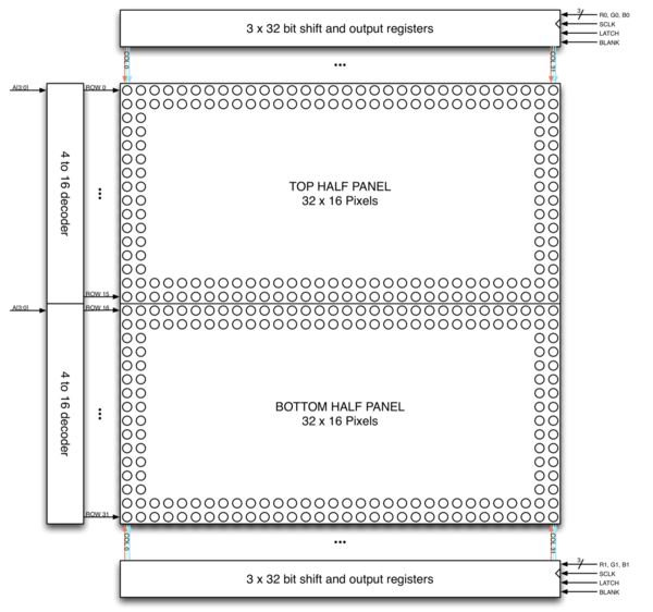
The LED panel contains 1024 RGB LEDs arranged in a matrix of 32 rows and 64 columns. Each RGB LED contains separate red, green, and blue LED chips assembled together in a single package. The display is subdivided horizontally into two parts, the top half and bottom half consists of 64 columns and 16 rows respectively.
There are different drivers for controlling display’s columns and another set of drivers for controlling rows. To illuminate an LED, the drivers for both the column and the row for that LED must be turned on. To change the color of an LED, the red, green, and blue chips in each LED package are controlled individually and have their own column drivers.
The panel contains six sets of column drivers; three for the top half of the display and three for the bottom. Each driver has 32 outputs. The three drivers for the top of the display drive the red, green, and blue chips in each of the 64 columns of LEDs in rows 0 to 15 of the panel. The three drivers for the bottom of the display drive the red, green, and blue chips in each of the 64 columns of LEDs in rows 16 to 31 of the panel. The red, green, and blue column drivers for the top half of the display are attached respectively to the R0, G0, and B0 data inputs. The red, green, and blue column drivers for the bottom half of the display are attached respectively to the R1, G1, and B1 data inputs. All six of the 32-bit drivers share common SCLK, LATCH, and BLANK signals.
The display is multiplexed and has a 1/16th duty cycle. This means that no more than one row out of the 16 in the top half of the display and one row out of the 16 in the bottom half of the display are ever illuminated at once. Furthermore, an LED can only be on or off. If both the row and column for an LED are turned on, the LED will be illuminated; otherwise, the LED will be off. To display an image, the entire LED panel must be scanned fast enough so that it appears to display a continuous image without flickering. To display different colors and different brightness levels, the brightness of the red, green, and blue LED chips within each LED package must be adjusted by varying the amount of time that each LED chip is on or off within a single refresh cycle.
Hardware Interface
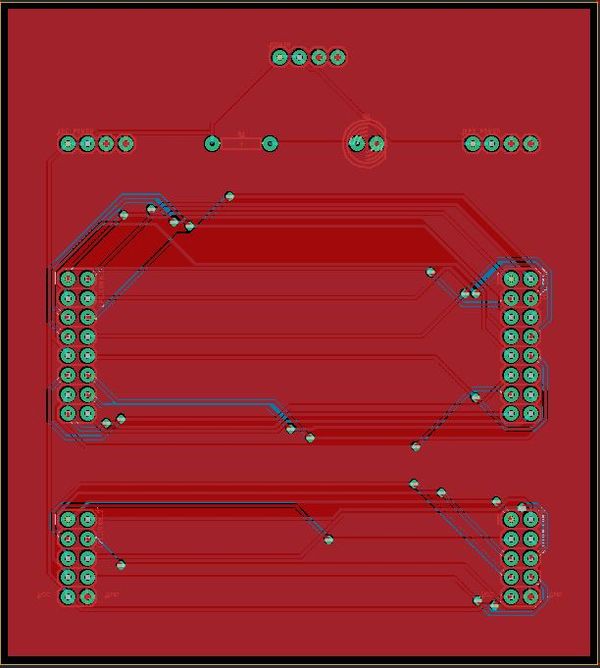
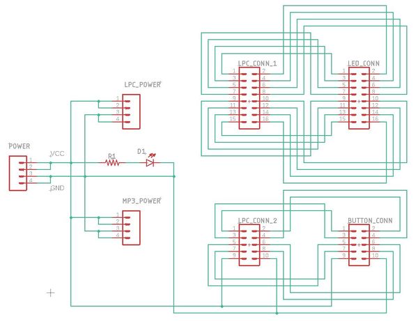
For the hardware, we designed a PCB board that would be used as a hub to connect the LPC4078, the LED Matrix, and the controls together. The images below show the PCB Board and the PCB schematic that were designed. The PCB features 26 pin connections that can be used to connect the pins of the LPC4078 to the LED Matrix, an MP3 decoder, a controller, or any other components. The PCB board was designed using the EAGLE PCB Design Software.
PCB Board Design
This is a screenshot of the PCB Board that was designed through EAGLE. All of the parts used for the design were plated through holes. This allowed for simple header pins to be soldered directly to the PCB rather than using surface mounted parts.
PCB Schematic Design
This is a screenshot of the PCB Board Schematic that was designed through EAGLE and used to build design the PCB Board. The schematic features a large number of header pins that can be used to connect the LPC4078 to a variety of components, including an LED matrix, a button controller, and an MP3 Decoder. Several pins were also added to supply both a VCC and a GND to all of the components used in the design.
Software Design
The main code logic blocks which are the random obstacle generation, obstacle motion enabling and obstacle color mismatch detection blocks are as follows: OBSTACLE GENERATION:
bool generate_obstacle_rand(void) {
 bool ret;
 uint8_t randomize_color = (rand() % 4) + 1; // generating random colour
 rand_row = (rand() % 17) + 9;  // generating a random row for obstacle generation
 while (!(((row_old - rand_row) >= obstacle_gap) || ((rand_row - row_old) >= obstacle_gap))) {  // loop  is used to generate a new row number in comparison with the last generated row number
   rand_row = (rand() % 17) + 9;
 }
 while (colour_old == randomize_color || ((colour_old == yellow1) && (randomize_color == cyan1))) {
   randomize_color = (rand() % 3) + 1;
 }
 if (randomize_color == cyan1) {
   randomize_color = yellow1;
 }
 int8_t row = rand_row;
 for (int8_t col = 63; col > 52; col--) {
     drawPixel(row, col, randomize_color);
     drawPixel(row + 1, col, randomize_color);
     ret = 0;
 }
 row_old = rand_row;
 colour_old = randomize_color;
 ret = 1;
 return (ret);
}
OBSTACLE MOTION LOGIC:
void shift_obstacle_left(void) {
 int8_t temp;
 for (int8_t row1 = 9; row1 < 28; row1++) {
   for (int8_t col1 = 0; col1 < 63; col1++) {
     ledmatrix_buffer[row1][col1] = ledmatrix_buffer[row1][col1 + 1]; // move all element to the left except first
   }
   ledmatrix_buffer[row1][63] = 0;
 }
}
OBSTACLE BLEND COLOR MISMATCH DETECTION:
bool detect_collision(void) {
 bool detect = 0;
 if (((ledmatrix_buffer[autorunner_row][4] != ledmatrix_buffer[autorunner_row][5]) &&
      (ledmatrix_buffer[autorunner_row][5] != 0)) ||
     ((ledmatrix_buffer[autorunner_row + 1][5] != ledmatrix_buffer[autorunner_row + 1][6]) &&
      (ledmatrix_buffer[autorunner_row + 1][6] != 0)) ||
     ((ledmatrix_buffer[autorunner_row + 2][4] != ledmatrix_buffer[autorunner_row + 2][5]) &&
      (ledmatrix_buffer[autorunner_row + 2][5] != 0)) ||
     ((ledmatrix_buffer[autorunner_row + 3][5] != ledmatrix_buffer[autorunner_row + 3][6]) &&
      (ledmatrix_buffer[autorunner_row + 3][6] != 0))) {
   detect = 1;
 } else {
   detect = 0;
 }
 return (detect);
}
MP3 Player Tasks:
void MP3_Play_Task(void *pvParameters) {
       BYTE decoder_buffer[512];
       mp3_decoder_init();
       while(1)
       {
               if(xQueueReceive(MP3Queue, decoder_buffer, 1000))
               {
                       //printf("track playing");
                       play_mp3_track(decoder_buffer);
               }
       }
}
void Read_MP3_Task(void *pvParameters) {
       while(1)
       {
               readMP3File();
               vTaskDelay(1000);
       }
}
MP3 Decoder Driver:
void mp3_decoder_init() {
   ssp__init(24);
   gpio_x__set_as_output(1, 28); //Set pin 1.28 as output for RESET signal
   gpio_x__set_as_output(1, 20); //Set pin 1.20 as output for DCS signal
   gpio_x__set_as_output(1, 31); //Set pin 1.31 as output for CS signal
   //gpio_x__set(0, 25, true); //Set pin 0.25 high initially
   //gpio_x__set(0, 26, true); //Set pin 0.26 high initially
   //gpio_x__set(1, 30, true); //Set pin 1.30 high initially
   gpio_x__set_high(1, 28);
   gpio_x__set_high(1, 20);
   gpio_x__set_high(1, 31);
gpio_x__set_as_input(0, 26); //Set pin 0.26 as input for DREQ
   write_to_decoder(SCI_MODE, 0x0800);         //Set up MODE register
   //write_to_decoder();                         //Set up Bass/Treble register
   write_to_decoder(SCI_CLOCKF, 0x2000);       //Set up Clock register
   write_to_decoder(SCI_AUDATA, 0xAC45);       //Set up AudioData register               `
   write_to_decoder(SCI_VOL, 0x2424);          //Set up Volume register
   uint16_t data1 = read_from_decoder(SCI_MODE);
   uint16_t data2 = read_from_decoder(SCI_CLOCKF);
   uint16_t data3 = read_from_decoder(SCI_AUDATA);
   uint16_t data4 = read_from_decoder(SCI_VOL);
   printf("SCI_MODE = %x\n", data1);
   printf("SCI_CLOCKF = %x\n", data2);
   printf("SCI_AUDATA = %x\n", data3);
   printf("SCI_VOL = %x\n", data4);
//u0_dbg_printf("mode data = %x\n", data);
}
void play_mp3_track(uint8_t buffer[]) {
   for(uint8_t byteIndex = 0; byteIndex < 16; byteIndex++)
   {
       while(!(gpio_x__get_level(0, 26)))
       {
           //vTaskDelay(1);
       }
       gpio_x__set(1, 20, false);
       //gpio_x__set_low(0, 26);
       //gpio_x__set_low(1, 30);
       for(uint16_t i = 32 * byteIndex; i < (32 * byteIndex) + 32; i++)
       {
           ssp__exchange_byte(buffer[i]);
       }
       while(!(gpio_x__get_level(0, 26)))
       {
           //vTaskDelay(1);
       }
       gpio_x__set(1, 20, true);
       //gpio_x__set_high(0, 26);
       //gpio_x__set_high(1, 30);
   }
}
Implementation
This section includes implementation, but again, not the details, just the high level. For example, you can list the steps it takes to communicate over a sensor, or the steps needed to write a page of memory onto SPI Flash. You can include sub-sections for each of your component implementations.
In order to play music from the MP3 decoder, the MP3 file needs to be pulled from an SD card and into a buffer, and the data needs to be fed to the MP3 Decoder through the SPI Bus.
Testing & Technical Challenges
Describe the challenges of your project. What advise would you give yourself or someone else if your project can be started from scratch again? Make a smooth transition to testing section and described what it took to test your project.
Include sub-sections that list out a problem and solution, such as:
<Bug/issue name>
Discuss the issue and resolution.
Conclusion
Conclude your project here. You can recap your testing and problems. You should address the "so what" part here to indicate what you ultimately learnt from this project. How has this project increased your knowledge?
Project Video
Upload a video of your project and post the link here.
Project Source Code
References
Acknowledgement
Any acknowledgement that you may wish to provide can be included here.
References Used
List any references used in project.
Appendix
You can list the references you used.


