Difference between revisions of "F19: Smacman"
Proj user2 (talk | contribs) (→MP3 Decoder) |
Proj user2 (talk | contribs) (→References Used) |
||
| Line 740: | Line 740: | ||
====== RGB LED Matrix Interfacing and Designing ====== | ====== RGB LED Matrix Interfacing and Designing ====== | ||
* [https://cdn.sparkfun.com/assets/7/d/7/5/6/M6464-P3.pdf Datasheet and LED Matrix parameters] | * [https://cdn.sparkfun.com/assets/7/d/7/5/6/M6464-P3.pdf Datasheet and LED Matrix parameters] | ||
| − | * [https:// | + | * [https://learn.adafruit.com/32x16-32x32-rgb-led-matrix Power and pin connections] |
| − | * [https:// | + | * [https://bikerglen.com/projects/lighting/led-panel-1up/ Reference for setting up and testing LED Matrix] |
====== General/Miscellaneous ====== | ====== General/Miscellaneous ====== | ||
| − | * [http:// | + | * [http://www.espruino.com/Pixl.js+Pong Pong Game Tutorial] |
| + | * [https://www.freertos.org/Documentation/RTOS_book.html FreeRTOS Documentation and Reference Manual] | ||
* [https://sjsu-dev2.readthedocs.io/en/latest/?badge=latest SJTwo-c Documentation] | * [https://sjsu-dev2.readthedocs.io/en/latest/?badge=latest SJTwo-c Documentation] | ||
=== Appendix === | === Appendix === | ||
You can list the references you used. | You can list the references you used. | ||
Revision as of 14:35, 18 December 2019
Contents
- 1 Grading Criteria
- 2 SMACMAN
- 3 Abstract
- 4 Objectives
- 5 Introduction
- 6 Delivery Schedule
- 7 Parts List & Cost
- 8 Design & Implementation
- 9 Game Casing
- 10 Testing & Technical Challenges
- 11 Conclusion
- 12 References
Grading Criteria
- How well is Software & Hardware Design described?
- How well can this report be used to reproduce this project?
- Code Quality
- Overall Report Quality:
- Software Block Diagrams
- Hardware Block Diagrams
- Schematic Quality
- Quality of technical challenges and solutions adopted.
SMACMAN
Abstract
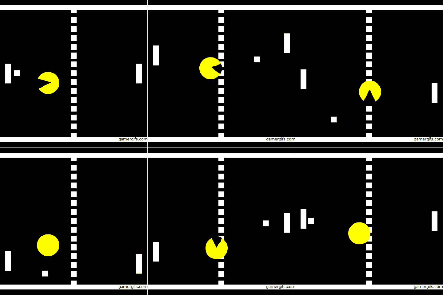
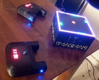
Our team has created a unique 2 player game involving a central screen of 64x64 LED matrix and two auxiliary controllers. The two opponents will face one another and will have a paddle on their side. A ball will travel between players which they have to deflect away. Additionally, each player will have a “monster” that will continuously move towards the ball and try to eat the ball. If a monster eats the ball, that opponent of the owner of the monster will lose. Therefore, it is beneficial for a player to try to place the ball closer to their monster and further away from the opponent’s monster in order to score. Additionally, if the ball contacts the side of the screen behind the player’s paddle, they will also lose. As the game progresses, the speed of the ball will increase and eventually, there will be variation in the movement of monster. The controllers(xBee--XB24-AWI) will be wireless and communicate with the master board which runs the game and drives the 64x64 LED matrix.The MP3 module(VS 1053) reads music files from an SD card and plays the music through a speaker interfaced with the board in the background.
Objectives
The main objective of the project is to develop a 2D two player Smacman game. Other milestones to achieve are as below:
- Change the direction and speed of the monster differently at different levels, depending on the direction of the ball on LED Matrix in real time.
- The controller which does wireless transfer of accelerometer values is used to control the movement of the ball
- Play music in the background and game sounds using MP3 Decoder.
- Design PCB for Master and the Controller which will interface all the peripheral devices to the SJ-two boards.
Introduction
The project is broadly divided into three nodes:
1. Master Node: The master node (one SJ2 board) receives the data from the controller nodes via XBee module which is used to control the paddle movement which will eventually control the game. It recursively polls to receive control packets from the controller nodes and updates the paddle movements as per user's input. The master node also controls visual display on the LED Matrix and the game logic.
2. Controller Node: The controller node (two SJ2 boards) consist of the XBee modules which transmits control packets to the master node using fault-tolerant broadcast wireless UART protocol.
3. Music Node: The music node (one SJ2 board) provides background music to the game which enhances the experience of the game.
About the game
- Both Players should try to hit the ball with the paddle placed on their side.
- Press switch on the controller SJ-Two board to start the game.
- Tilt the controller left or right to move the paddle.
- Hit the ball with your paddle before the monster eats it to get a score.
- To manipulate the speed and the direction of the ball move the paddle in the same or in the opposite direction of the ball.
- Avoid the monster of opposite player to eat the ball in your side, if this happens then the game is over, else the ball continues to move between the paddles.
- The speed of the monster increases when the ball will move in opposite direction to catch the ball.
- Level 1 has the monster of opposite player moving at your side along the edges. If any player exceeds a score of 33 then me move to Level 2.
- Level 2 has the monster of opposite player moving along x-axis at your side. If any player exceeds a score of 66 then me move to Level 3.
- Level 3 has the monster of opposite player moving along x-axis and y-axis at your side. If any player reaches a score of 100 then that player wins the game.
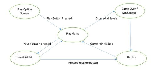
- Both the Players can play and pause the game anytime and resume from where the game was paused.
Team Members & Responsibilities
- Nick Schiffer
- XBEE, Controller Functionality, Communication Architecture, Game Logic Development, Enclosures, PCB Designing.
- Mohit Ingale
- LED Driver, Game Logic Development, Enclosures, PCB Designing.
- Ayesha Siddiqua
- Graphic Driver, Game Logic Development.
- Shreya Patankar
- Splash Screen Graphics Driver, Game Logic Development, MP3 Decoder.
Delivery Schedule
Project Repository Link: Github Project
| Week# | Date | Task | Status | Actual Completion Date |
|---|---|---|---|---|
| 1 | 10/1/2019 |
|
|
|
| 2 | 10/15/2019 |
|
|
|
| 3 | 10/22/2019 |
|
|
|
| 4 | 10/29/2019 |
|
|
|
| 5 | 11/5/2019 |
|
|
|
| 6 | 11/12/2019 |
|
|
|
| 7 | 11/19/2019 |
|
|
|
| 8 | 11/26/2019 |
|
|
|
| 9 | 12/3/2019 |
|
|
|
| 10 | 12/10/2019 |
|
|
|
| 11 | 12/17/2019 |
|
|
|
Parts List & Cost
| Item# | Part Desciption | Vendor | Qty | Cost |
|---|---|---|---|---|
| 1 | SJTwo Boards | Purchased from Preet | 4 | $200.00 |
| 2 | 64x64 RGB LED Matrix | Saprkfun | 1 | $75.00 |
| 3 | Wiring Components and Cable | Waveshare | 1 | $20.00 |
| 4 | 3D printer filament spool(s) | HATCHBOX | 2 | $40.00 |
| 5 | XBEE Modules | From Preet and Adafruit | 3 | $27.00 |
| 6 | Batteries | Local | 2 | $4.00 |
| 7 | I2C 7-seg screens | Adafruit | 2 | $18.00 |
| 8 | XBee Programmer Boards | Waveshare | 3 | $35.00 |
Design & Implementation
Hardware and PCB Design
PCB Design
There are many softwares available for PCB design, among them Eagle is more popular. We chose EasyEDA for PCB design over Eagle because, it is an online free software so we din't have to worry about the license. We faced many issues while using this software but we found a good tutorial on youtube. The issues which we faced are discussed in the issue section of this wiki.
The steps involved in the PCB design process are described in the next section.
Schematic Design:
Our project can be divided into two main circuits, first is game display circuit and second is a console circuit. We decided to design separate PCB for both circuits as doing so can make wiring easy and improve the user experience.
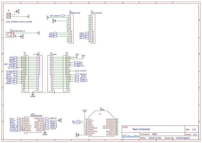
Master Controller PCB schematic:
We have created on top PCB to mount on SJTwo board. One circuit will do the wire interfacing of SJTwo board to xbee, mp3 decoder, led matrix. This is the master board and it will recieve values from all the controllers and peripherals. This is our Main Circuit. We Also have a power jack to power all the peripheral devices so that we don't have to power SJOne board from PC while we are playing the game.
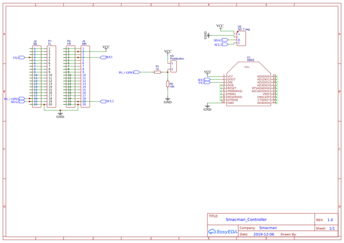
Controller PCB schematic:
We have created on top PCB to mount on SJTwo board. One circuit will do the wire interfacing of SJTwo board to xbee of the two game controllers which will in turn send the values of acce;lerometer to the master xbee interfaced PCB. We Also have a power jack to power all the peripheral devices so that we don't have to power SJOne board from PC while we are playing the game.
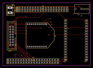
PCB Layout:
After schematic design, the most important step is to connect the PCB layout. In EasyEDA components is not automatically associated with it's PCB footprint, so it's user's responsibility to connect right PCB footprint with the right components. In our case, we did not have the footprint of JLC connector and Rocker switch. so, we created it in a different window and saved it. The amazing feature of KiCAD is once we have done with PCB layout we can visualize PCB in 3D by pressing just one button. Below are actual screenshots of both, PCB layout & their 3D model.
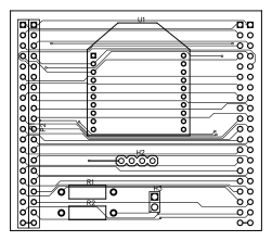
PCB layout Designed on EasyEDA:
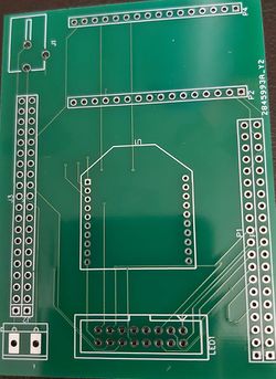
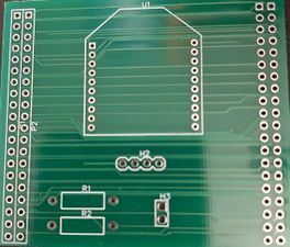
Printed PCB :
We chose JLC PCB to manufacture our PCB because, it is the cheapest and convenient option available for any prototype PCB manufacturing. It just cost us $2 for quantity of 10 PCB and $12 for shipment. We received manufactured PCB in just 3 days. Followings are actual photos of manufactured & assembled PCBs.
Hardware Interface
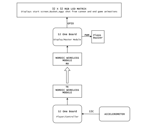
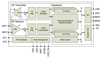
Hardware design diagram above gives an overview of the entire system which consists of the two SJ-One controllers: one board is used as Control Module and other board is used as the Display Module.
- The Console Module uses the onboard accelerometer on SJ-One which is interfaced via I2C protocol. The calibrated accelerometer values are then used to determine the basket position on the LED Matrix.
- The Display Module SJ-One board is used to control a 32*32 RGB LED Matrix.This matrix displays the basket, eggs shot from the cannon.The movement of the basket is as per the orientation value received from the Control Module, through Wireless Module. It also consists of Peizo buzzer which is controlled via PWM pin.
Hardware Components Design, Description Implementation
RGB LED Matrix
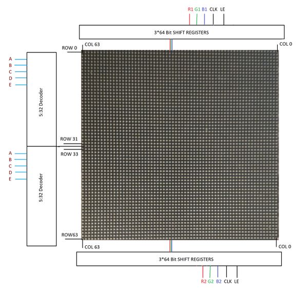
A 64x64 RGB LED Matrix Panel is used as a display. It has 4096 full-color RGB LEDs. Each LED can be independently addressed and controlled. It requires at 13 digital GPIOs to control the LED matrix. The led matrix has 2 IDC connectors DATA_IN and DATA_OUT on the back, we can cascade multiple panels and make a huge screen together. The LED display is constructed using a decoder to decode address rows. A 64 bit Shift register should be clocked for enabling the color. When the row is low we need to select which all pixels in the column are to be configured with the required color. This is done by clocking the 64Bit shift register. There are 6 64Bit registers each for R1 R2 B1 B2 G1 G2. A single clock is interfaced to all these 6 64bit shift registers. So at once we shift and fill the required color for the column display. Once the clocking and shifting the register is completed we need to latch this data to the register. The register data is sent out to all the row lines and that Row line which is pulled low by the decoder will receive this data and corresponding pixels are turned on.
RGB LED matrix pins:
| S.NO | RGB LED pins | Function |
|---|---|---|
| 1 | R1 | High R data |
| 2 | G1 | High G data |
| 3 | B1 | High B data |
| 4 | R2 | Low R data |
| 5 | G2 | Low G data |
| 6 | B2 | Low B data |
| 7 | A | Row select A |
| 8 | B | Row select B |
| 9 | C | Row select C |
| 10 | D | Row select D |
| 11 | E | Row select E |
| 12 | CLK | Clock signal. |
| 13 | OE | Output enables to cascade LED panel. |
| 14 | LAT | Latch denotes the end of data. |
| 15 | VCC | 5V |
| 16 | GND | GND |
Row Selection
The RGB matrix has a 5:32 decoder. This decoder takes 5 bits as input and decodes the corresponding row to be kept low. There are five address inputs to the display marked A, B, C, D and E. Based on the truth table, only one input is active (low) at a time. The outputs of the decoder are connected to a P-Channel MOSFET because the decoder itself can only handle low currents and cannot drive a row of LEDs directly. The P-Channel MOSFET provides the high current needed to drive a row of LEDs. The decoder outputs are shared between every 32 outputs. Since, the 5-to-32 address decoder select rows in parallel like 1 and 33, 2 and 34, repeating that pattern until row 32 and 64.
Column Selection
The column data is stored in a 64-bit serial-in, a parallel-out shift register. The shift register is designed to work with LEDs and implements a constant-current system that ensures the LED brightness remains uniform. R1 G1 B1 is used for configuring the color for the top half of the display and R2 G2 B2 for the bottom half of the display. For 64 rows using with 32 outputs of the decoder, we must have unique data for each row pair. When Row 1 and Row 33 are selected, we must provide each row with unique data. This forces us to use two different shift registers for each row pair, an upper register, and a lower register. Because of this, the display is divided into an upper half and a lower half. The data is shifted into the top half via the R1, G1 and B1 signals on the connector. The bottom halves data is supplied by the R2, G2 and B2 signals on the connector. Then, since our display is 64 pixels wide, we use 64-bit shift registers to hold all 64 bits of pixel data for a single row. Each half of the display is controlled by 3 shift registers, one for each color. First, Row 1 and Row 33 are selected then 64 bits of data are shifted into each color’s shift register (R1, G1, B1), and then latched. At the same time, 64 bits of data are also shifted into each color’s shift register for the bottom half (R2, G2, B2), and then latched. The process repeats 31 more times, each time incrementing the rows are selected until every line has been updated.
In order to display something on the LED panels the following steps need to be performed by the driver
- Shift the pixel data for row 1 into the top column drivers and the pixel data for row 33 into the bottom column drivers using the R1, G1, B1, R2, G2, and B2 data inputs and the SCLK shift clock signal.
- Clear the blanking signal to blank the display.
- Set the address input to 1.
- Latch the contents of the column driver's shift registers to the output registers using the LATCH signal.
- Make the blanking signal high to display rows 1 and 33.
- Repeat the process for each of the pairs of rows in the display for 31 times.
Specifications:
The LED display used in our project is a 64*64 pixel panel with a pixel pitch of 3mm. More specifications are tabulated.
- Operating voltage: DC 5V
- Average power consumption: <500W/㎡
- Maxim Power Consumption: <1000w/㎡
- Pixel: 64x64=4096
- Level of viewing Angle: ≧160°
- Control mode: Synchronous control
- Drive mode: 1/16 scan rate
- Repetition frequency: ≧60Hz
- White Balance Brightness: ≧1200cd/㎡
- Refresh frequency : ≧300Hz
- MTTF: ≧5000 hours
- Service Life: 75000~100000 hours
- Pixel pitch: 3mm
- Thickness: 11mm
MP3 Decoder
| In our project,we have calibrated the accelerometer based on the values of X,Y and Z co-ordinates corresponding to different orientations of the accelerometer to control the horizontal movement of the Basket int the game to catch the eggs on the screen. This has also helped us decide and control the speed of the basket. As shown in the code snippet below the x movement on the right is determined based on the x co-ordinate and the console sensitivity which you wish to set.Similarly movement on the left can also be calculated for further use. |
Code snippet for creating musical tones by varying frequency:
int fire[]=
{
		550,/*twice the freq of this and use always tempo as 40 */
		404,
		315,
		494,
		182,
		260,
		455,
		387,
		340
};

void fire_sound_level(void){
	 for(int i = 0;i < 8;i++)
		 {
		 	 uint8_t tempo = 40;
		 	 	 while(tempo)
		 	 	 {
					pwm.SetFrequency(fire[i]*2);
					pwm.SetDutyCycle(pwm.k2_1,50);
					pwm.PwmEnableMode(true);
					tempo--;
		 	 	 }
		 }
		 pwm.PwmEnableMode(false);
	}
Control Module
Accelerometer:
| In our project,we have calibrated the accelerometer based on the values of X,Y and Z co-ordinates corresponding to different orientations of the accelerometer to control the horizontal movement of the Basket int the game to catch the eggs on the screen. This has also helped us decide and control the speed of the basket. As shown in the code snippet below the x movement on the right is determined based on the x co-ordinate and the console sensitivity which you wish to set.Similarly movement on the left can also be calculated for further use. |
Code snippet for Accelerometer Calibration:
if (((x_coordiante > px_coordiante + CONSOLE_SENSITIVITY) && (x_coordiante <= CONSOLE_TILT_RANGE) ))
{
        boardOrientation=left;
        bskObj.speed=BASKET_SPEED;
        px_coordiante=x_coordiante;
}
    //left
    else if((x_coordiante<px_coordiante-CONSOLE_SENSITIVITY && x_coordiante>=-CONSOLE_TILT_RANGE))
{
        boardOrientation=right;
        bskObj.speed=BASKET_SPEED;
        px_coordiante=x_coordiante;
}
else if(x_coordiante>CONSOLE_TILT_RANGE ){
        boardOrientation=left;
        bskObj.speed=BASKET_SPEED;
}
else if(x_coordiante<-CONSOLE_TILT_RANGE ){
        boardOrientation=right;
        bskObj.speed=BASKET_SPEED;
    }
else
{
        boardOrientation=invalid;
        py_coordiante=y_coordiante;
}
Wireless Module:
Code snippet for Wireless Transmitter:
struct pckt
{
    int16_t x;
    int16_t y;
    int16_t z;
    int16_t buttonPressed=0;
};
void WirelessTx(void *p)
{
       while(1)
       {
           pckt var;
           var.x = AS.getX();/values from accelerometer*/
           var.y = AS.getY();
           var.z = AS.getZ();
           pckt var;
             while(1)
             {
                 if(SW.getSwitch(1))
                 {
                     var.buttonPressed=1;
                     vTaskDelay(300);
                 }
                 else if(SW.getSwitch(2))
                 {
                     var.buttonPressed=2;
                     vTaskDelay(300);
                 }
           wireless_send(REM, mesh_pkt_nack,(pckt*)&var, 8, 0);
           vTaskDelay(50);
             }
       }
}
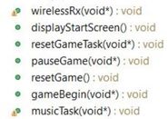
Code snippet for Wireless Receiver: void wirelessRx(void* p)
{
while(1)
{
mesh_packet_t rcvPkt;
int timeout_ms = 50;
if(wireless_get_rx_pkt(&rcvPkt, timeout_ms)){
iphObj.x_coordiante = (int16_t)(*((uint16_t*)(rcvPkt.data+0)));
iphObj.y_coordiante = (int16_t)(*((uint16_t*)(rcvPkt.data+2)));
iphObj.z_coordiante = (int16_t)(*((uint16_t*)(rcvPkt.data+4)));
iphObj.buttonPressed= (int16_t)(*((uint16_t*)(rcvPkt.data+6)));
if(iphObj.buttonPressed==1 )
{
xSemaphoreGive(playPauseHandler);
}
else if(iphObj.buttonPressed==2 )
{
xSemaphoreGive(resetGameHandler);
}
}
vTaskDelay(50);
}
}Tasks and Flow Control
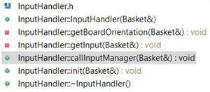
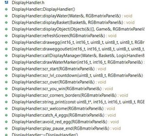
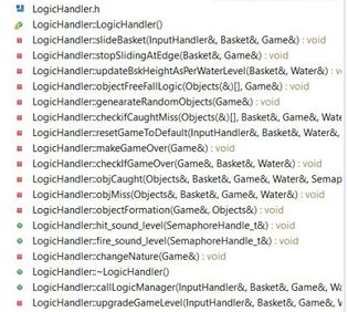
'Input_handler:' This is class, which contains all the functions which controls the position of the basket. Which is in turn depends on the console unit orientation value received from wireless task. This task also receives status of button press from the console unit. The values are received as a structure. Wireless task checks for button press and accordingly changes the state of game.i.e for button 1 press it pauses the game and for button 2 press it restarts the game. The accelerometer values are used to calibrate the basket horizontal movement.Depending upon the x-axis values of console the basket slides horizontally. Display_handler: We have implemented the various functions to display the components used in our Game. It uses GFX matrix library to draw the shapes and pixel. Objects used in our game includes Baskets,Eggs,Cannon and Water. Apart form Object display Handler also has functions to implement the screens used in our Game like-Play/Pause screen,Game Over Screen,Win Screen. Game_Begin: This is a task which divided into Logic Handler, Input Handler and Display Handler. Input Handler read the input,Logic Handler implements various algorithms to generate eggs with random behavior,checks for game Over condition,sliding the basket depending upon the direction received from Input handler,speed of sliding ,Logic to determine the catch or miss of Egg and increment the water level on every miss.Display Handler deals with displaying objects on screen. Each handler class have its manager functions which calls all the private functions of respective handler. From the game Task we call these manager functions of all the handlers.Basic Game theory is to check the input,update the logic and display. we are implementing same thing using handlers for display,logic and input. Tasks in Console Module : Transmitter Task: This task periodically transmits the orientation values and button press status to the display module. Task Priority :1 (could be anything as it the only task running in the console).
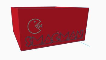
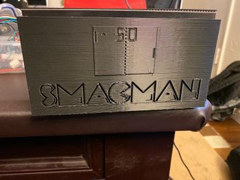
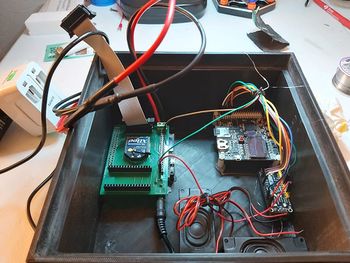
Game CasingSmacman is a two Player game. It is quiet inconvinient to play the game with all the wires and components lying around. So to facilitate this we 3D printed a basic enclosure for the two players controller as well as the Led matrix, which is big enough to accommodate zigbee module, MP3 Decoder and speakers, Master Board. We needed to put together all components in a single enclosure. The enclosure includes the spacing for SJTWO board with PCB mounted on top and the MP3 Decoder along with speakers. Testing & Technical ChallengesDescribe the challenges of your project. What advise would you give yourself or someone else if your project can be started from scratch again? Make a smooth transition to testing section and described what it took to test your project. Include sub-sections that list out a problem and solution, such as: <Bug/issue name>Discuss the issue and resolution. ConclusionConclude your project here. You can recap your testing and problems. You should address the "so what" part here to indicate what you ultimately learnt from this project. How has this project increased your knowledge? Project VideoUpload a video of your project and post the link here. Project Source CodeReferencesAcknowledgementAny acknowledgement that you may wish to provide can be included here. References UsedList any references used in project. WIRELESS CONTROLLERMP3 DECODERRGB LED Matrix Interfacing and Designing
General/MiscellaneousAppendixYou can list the references you used. |
