Difference between revisions of "F19: Road Max Fury"
Proj user6 (talk | contribs) (→Conclusion) |
Proj user6 (talk | contribs) (→Testing & Technical Challenges) |
||
| Line 393: | Line 393: | ||
== Testing & Technical Challenges == | == Testing & Technical Challenges == | ||
| − | + | ===Issues, Challenges and solutions to get past them=== | |
| − | + | '''1. RGB LED Matrix Display driver''' | |
| − | + | '''2. MP3 Decoder''' | |
| − | + | '''3. Low level Audio Sound''' | |
| − | |||
== Conclusion == | == Conclusion == | ||
Revision as of 04:28, 16 December 2019
Contents
Project Title
Road Max Fury- Game using FreeRTOS
Abstract
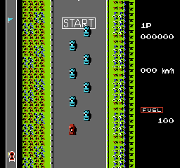
Road Max Fury is a game based on a classic car racing arcade game developed in 1984 by Konami named Road Fighter. We planned to reproduce this game as a part of our CMPE 244 project. The goal is to reach the finish line without running out of time, avoiding other cars on the road or running out of fuel .The fuel is refilled by hitting petrol pump which the player can encounter at random location during the course of the game. The player also needs to prevent car from hitting the edge of the road to prevent the collision.
Objectives & Introduction
The primary goal of this project is to develop a racing game based on Road Fighter using FreeRTOS using SJ2 Board and to drive the LED matrix. The game's objective is to finish the finish line before running out of fuel and avoiding the obstacles and other cars on the road. The LED matrix is interfaced using the GPIO pins and the on board accelerometer is interfaced using I2C communication protocol.
Objectives:
- Write drivers to display road, car, traffic, score, fuel status on the RGB LED matrix and update the display continuously.
- Write drivers to give directions from the input devices ie accelerometer and filter the values to get accurate and desired values.
- Implement game algorithm for movement of car, random obstacle car and update scores and fuel status.
- Create FeeRTOS tasks for display, accelerometer values, game logic and understand the communication and synchronization between them.
Team Members & Responsibilities
Schedule
| Week# | Date | Deliverables | Status |
|---|---|---|---|
| 1 | 09/29 |
|
|
| Week# | Date | Deliverables | Status |
| 2 | 10/12 |
|
|
| Week# | Date | Deliverables | Status |
| 3 | 10/16 |
|
|
| Week# | Date | Deliverables | Status |
| 4 | 10/23 |
|
|
| Week# | Date | Deliverables | Status |
| 5 | 10/30 |
|
|
| Week# | Date | Deliverables | Status |
| 6 | 11/06 |
|
|
| Week# | Date | Deliverables | Status |
| 7 | 11/13 |
|
|
| Week# | Date | Deliverables | Status |
| 8 | 11/24 |
|
|
| Week# | Date | Deliverables | Status |
| 9 | 12/1 |
|
|
| Week# | Date | Deliverables | Status |
| 10 | 12/8 |
|
|
| Week# | Date | Deliverables | Status |
| 11 | 12/13 |
|
|
Parts List & Cost
| Part | # | Cost | Source |
|---|---|---|---|
| SJ2 Board | 1 | $55.00 | Preet |
| Azerone 32 x 64 LED Matrix | 1 | $34.95 | https://www.amazon.com/gp/product/B07F2JW8D3/ref=ppx_yo_dt_b_asin_title_o01_s00?ie=UTF8&psc=1 |
| HiLetgo MP3 Decoder | 1 | $7.64 | https://www.amazon.com/gp/product/B0725RHR4D/ref=ppx_yo_dt_b_asin_title_o00_s00?ie=UTF8&psc=1 |
| Female Male DC Power Plug Terminal Adapter | 1 | $6.54 | https://www.amazon.com/gp/product/B00W058HHQ/ref=ppx_yo_dt_b_asin_title_o00_s00?ie=UTF8&psc=1 |
| PCB | 1 | $19.00 | https://jlcpcb.com/?gclid=Cj0KCQiA0NfvBRCVARIsAO4930nyv9BTfWyVz9KqLUyJRwS_FK0Hp6ldhHof8L-kW1jctHch8ahMC7waAhpSEALw_wcB |
| Digital Audio Amplifier | 1 | $ | |
| Push Button Switch | 1 | $7.99 | https://www.amazon.com/gp/product/B07SVTQ7B9/ref=ppx_yo_dt_b_asin_title_o08_s00?ie=UTF8&psc=1 |
| Audio Speakers | 1 | $7.99 | |
| 40 Pin GPIO Ribbon Cable | 1 | $ 9.99 | https://www.amazon.com/gp/product/B01H53OK5U/ref=ppx_yo_dt_b_search_asin_title?ie=UTF8&psc=1 |
| 3.5mm TS Mono Male to 2 Pin Screw Terminal Female AUX Headphone Balum Converter | 1 | $ | |
| 1 | $ |
Design & Implementation
The design section can go over your hardware and software design. Organize this section using sub-sections that go over your design and implementation.
Hardware Design
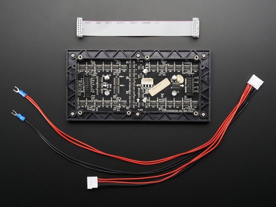
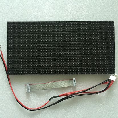
The hardware design employs the use of 64x32 RGB LED matrix panel which is the most important part of the project, this uses four data lines namely A,B,C and D which can be addressed and used to control each LED which has following technical specifications:
Dimensions:
- 110.1 x 5 x 0.2 inches
Operation Power
- AC100-240V 50-60HZ Switch-able
- 5V regulated power input, 4A max (all LEDs on)
- 5V data logic level input
- 4mm pitch
- Module Refresh: 1560hz
Hardware Interface
In this section, you can describe how your hardware communicates, such as which BUSes used. You can discuss your driver implementation here, such that the Software Design section is isolated to talk about high level workings rather than inner working of your project.
Software Design
Show your software design. For example, if you are designing an MP3 Player, show the tasks that you are using, and what they are doing at a high level. Do not show the details of the code. For example, do not show exact code, but you may show psuedocode and fragments of code. Keep in mind that you are showing DESIGN of your software, not the inner workings of it.
Display Module
RGB LED Matrix:
| SJ One Board Pin | Name | Description |
|---|---|---|
| P1_14 | R1 | Top half red data |
| P4_29 | G1 | Top half green data |
| P0_7 | B1 | Top half blue data |
| P4_28 | R2 | Bottom half red data |
| P0_6 | G2 | Bottom half green data |
| P0_8 | B2 | Bottom half blue data |
| P0_26 | addrA | Address Input A |
| P1_31 | addrB | Address Input B |
| P1_20 | addrC | Address Input C |
| P1_28 | addrD | Address Input D |
| P2_0 | Clock | Shift clock |
| P2_2 | Latch | Shift in row data/Active High |
| P2_5 | Output Enable | Turn on selected rows/Active Low |
Implementation
This section includes implementation, but again, not the details, just the high level. For example, you can list the steps it takes to communicate over a sensor, or the steps needed to write a page of memory onto SPI Flash. You can include sub-sections for each of your component implementation.
Testing & Technical Challenges
Issues, Challenges and solutions to get past them
1. RGB LED Matrix Display driver
2. MP3 Decoder
3. Low level Audio Sound
Conclusion
We were able to successfully design the Road Max Fury game using the RGB LED Matrix and the SJ2 board. This project helped us in having a better understanding of the FreeRTOS scheduler tasks that were used to handle the various components of the game. The understanding developed in writing the display driver from the scratch proved beneficial in resolving issues since most of the available libraries are in C++ and we encountered many problems while porting and debugging in the initial testing phase. Even though there weren't many proper datasheets and reliable tutorials for the LED Matrix, some previous semester's project report on the same display helped us gain momentum in the initial stages. We also got to work on the MP3 decoder while incorporating audio for the game design. Not only did this project help us in understanding the practical possibilities with boards like SJ2 board but also instilled in us a sense of team work and accountability for individually assigned task that helped the team overall.
Project Video
Upload a video of your project and post the link here.
Project Source Code
- []


