Difference between revisions of "F13: Bulb Ramper"
Proj user9 (talk | contribs) |
(→Grading Criteria) |
||
| (26 intermediate revisions by 2 users not shown) | |||
| Line 1: | Line 1: | ||
| − | === | + | == Bulb Ramper == |
| − | |||
| − | |||
| − | |||
| − | |||
| − | |||
| − | |||
| − | |||
| − | |||
| − | |||
| − | |||
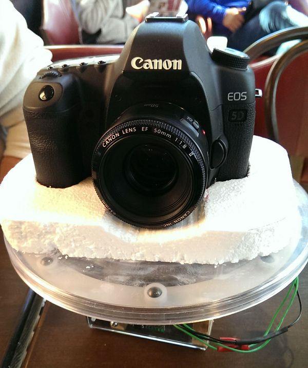
| − | + | [[File:CMPE240_F13_BulbRamper.jpg|600px|thumb|center|Bulb Ramper]] | |
| − | Bulb Ramper | ||
== Abstract == | == Abstract == | ||
| Line 102: | Line 91: | ||
|Finalize and deliver project | |Finalize and deliver project | ||
Demo project | Demo project | ||
| − | | | + | |The report was successfully completed. |
| + | Demonstration of the project was successfull. | ||
|} | |} | ||
| Line 152: | Line 142: | ||
== Design & Implementation == | == Design & Implementation == | ||
| − | |||
| − | |||
| − | |||
| − | |||
=== Hardware Design === | === Hardware Design === | ||
| Line 175: | Line 161: | ||
=== Hardware Interface === | === Hardware Interface === | ||
| − | There are | + | |
| + | [[File:CMPE240_F13_BulbRamper_Hardware Diagram.jpg]] | ||
| + | |||
| + | |||
| + | There are three main interfaces for our project: | ||
1. GPIO: GPIO is used for camera activation. It takes two GPIO ports in order to activate the camera shutter. One GPIO to focus and and the other GPIO to open the shutter. | 1. GPIO: GPIO is used for camera activation. It takes two GPIO ports in order to activate the camera shutter. One GPIO to focus and and the other GPIO to open the shutter. | ||
| − | 2. PWM output: | + | 2. UART: Main communication between the wifi chip and our terminal task. |
| + | |||
| + | 3. PWM output: | ||
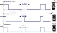
PWM, or Pulse Width Modulation, was used to control the 180-degree positional servo. The servo expects a train of pulses of varying widths. The pulses are repeated at a given period, typically set at 20 ms (50Hz). The width of the pulse is the code that signifies to what position the shaft should turn. The center position is usually attained with 1.3-1.5ms wide pulses, while pulse widths varying from 0.7-1ms will command positions all the way to the right (left), and pulse widths of 1.7-2ms all the way to the left (right). However, we found that the valid pulse widths were larger, ranging from 0.2 ms to 3.3 ms in our servo. Therefore, we expanded the range of pulse widths and converted the range into a degree range in software. The servo is connected to a 6V power supply and is controlled by PWM1 (P1.0) | PWM, or Pulse Width Modulation, was used to control the 180-degree positional servo. The servo expects a train of pulses of varying widths. The pulses are repeated at a given period, typically set at 20 ms (50Hz). The width of the pulse is the code that signifies to what position the shaft should turn. The center position is usually attained with 1.3-1.5ms wide pulses, while pulse widths varying from 0.7-1ms will command positions all the way to the right (left), and pulse widths of 1.7-2ms all the way to the left (right). However, we found that the valid pulse widths were larger, ranging from 0.2 ms to 3.3 ms in our servo. Therefore, we expanded the range of pulse widths and converted the range into a degree range in software. The servo is connected to a 6V power supply and is controlled by PWM1 (P1.0) | ||
| − | [[File: CmpE240 S13 BulbRamper PWM Pulse Widths Example.jpg|200px|thumb|center| | + | [[File: CmpE240 S13 BulbRamper PWM Pulse Widths Example.jpg|200px|thumb|center|PWM Pulse Widths Example]] |
| − | + | === Software Design === | |
| + | [[File:CMPE240_F13_BulbRamper_Project Flow.jpg|600px|thumb|right|Project Flow]] | ||
| + | |||
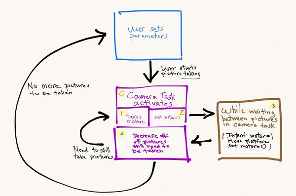
| + | The software flow is detailed up top. The general flow has the user setting each variable (# of pictures to take, motor movement, shutter time, etc). After which, the program will automatically take pictures and move on their own until the required pictures have been taken. | ||
| + | |||
| + | As part of the flow process, there is a loop that is repeated in order to repeatedly take pictures and move the camera platform. | ||
| − | |||
For our project, there are four different tasks: | For our project, there are four different tasks: | ||
1. Terminal Task: The terminal task is responsible for providing the input and output of the program. It is responsible for displaying data and modifying variables when the user wishes to change it. For example, the terminal task will allow the user to change the number of the pictures or time between pictures being taken. | 1. Terminal Task: The terminal task is responsible for providing the input and output of the program. It is responsible for displaying data and modifying variables when the user wishes to change it. For example, the terminal task will allow the user to change the number of the pictures or time between pictures being taken. | ||
| Line 198: | Line 194: | ||
4. Motor Task: Provides the functionality to drive the motor to different positions. | 4. Motor Task: Provides the functionality to drive the motor to different positions. | ||
| − | |||
| − | |||
| − | |||
=== Implementation === | === Implementation === | ||
| Line 221: | Line 214: | ||
== Testing & Technical Challenges == | == Testing & Technical Challenges == | ||
| − | + | There are several challenges in getting the project to work. Below are the list of the major ones that hopefully future students can avoid: | |
| − | + | ||
| + | 1) Have a good oscilloscope or at least, a volt meter. By seeing what is being sent out, it helps on the troubleshooting. In the beginning, the camera shutter wasn't being activated and it was hard to figure out what was happening without measuring what was coming out the chip. By having the equipment, it would have speed up troubleshooting process. The problem was that we put too high of a resistor inline with the optocoupler, so it did not have enough power for the LED to function and create a signal for the camera. | ||
| + | |||
| + | 2) User Interface: For the user interface, it is important to plan how your project will interact with the user. We ended using a model where the user can select each digit and then increment each digit individually to modify the number quickly. Instead of click a specific key a hundred times, he just needs to select the third digit and change it to "1". We could have gone with the user inputting "100" directly but that would require input checks to make sure they did not input a letter or weird characters. Another item that gave us trouble was how to display the number so the user will know which digit was being selected. We choose to display the text in a blinking fashion so the user can track it. This was simulated by writing out the number, erase it, write the number again except skip the selected digit, erase it again and repeat from the start. For example, the following will be displayed (backspace omitted) | ||
| + | 00000 | ||
| + | |||
| + | 0000 | ||
| + | |||
| + | 00000 | ||
| + | |||
| + | 0000 | ||
| + | |||
| + | By writing five numbers, erase it, write four numbers, erase and repeat; it looks as the selected digit was blinking. | ||
| + | |||
| + | Here is an example of the third digit being selected (once again, the erase portion is omitted) | ||
| + | |||
| + | 11111 | ||
| + | |||
| + | 11 11 | ||
| + | |||
| + | 11111 | ||
| + | |||
| + | 11 11 | ||
| + | |||
| + | We then put a delay between each printf so the simulated blinking wasn't too quick. | ||
| + | |||
| + | 3) The last of our challenges was making sure everything was working together. When we put all the tasks together, it took awhile to troubleshoot all the bugs. The scope of the programming bugs were not huge so we won't go into detail about it. However, the biggest asset for us when troubleshooting was using the printf function (or cout if using C++). By strategically placing printf functions, we can see which path the program took, what was inside a variable, and a whole multitude of other things. While we are aware there are debugging tools, the printf or cout has been the most reliable in terms of helping me figure out what the program was doing. | ||
| + | |||
| + | For example, if we expected only one of two conditions to occur (like an "if" statement), we would place a printf in each of them to make sure we weren't accidentally trigger a path we were suppose to take. In our project, we had an issue in the beginning with the motor increment factor. The motor wasn't incrementing in a set amount of steps, it just jumped from whatever starting position and went all the way to 180 on one giant step. To figure out what was happening, had the program print out what was in the motor increment variable each time the loop ran. This helped us realize it wasn't setting the variable in the way we thought it did. | ||
| + | |||
| + | ====== Testing our project ====== | ||
| + | |||
| + | We tested our project in several steps. We first divided the hardware portion between the both of us and each of us has to test the individual parts to make sure the part worked as expected. The camera shutter was tested with only the camera attached to the sjsu board; same thing for the motor. The wifly chip was also tested to see if it can communicate with another computer and so on. | ||
| + | |||
| + | After which, we incrementally added the hardware to the sjsu board piece by piece and doing a system level test. We first tested our project with the wi-fly board and the camera. Once that worked, we then added the motor to the mix. Each time, we had to try to break out project (input wrong values) so we can prevent any accidental fault conditions. | ||
| − | |||
=== My Issue #1 === | === My Issue #1 === | ||
| − | + | The biggest issue with our bulb ramping project turned out to be the user interface. We had to consider several factors while trying to decide which interface to use. | |
| + | |||
| + | 1) Amount of time to work on the project | ||
| + | 2) Usability of the settings | ||
| + | 3) Code for adaptability in the future | ||
| + | |||
| + | ==== Discussion of each point ==== | ||
| + | 1) The amount of time available to work on the project was a major factor in deciding to use the terminal interface. Since we were learning FREE RTOS, camera, wifi, & motor controls from scratch, it left us little time to work on the user interface. Our number one goal was to get the hardware system working nicely before moving to the refinement phase. In order to meet the project deadline, we choose to use the existing terminal task as a way to interact with the user. | ||
| + | |||
| + | 2) We choose to use only a few selected keys as our main way of manipulating user parameters. The alternative, having the user input directly the number or pictures or open shutter time would have made the system slightly more complex and time consuming. This is because we would have to do a check on the input to make sure the input data was valid. Instead, by limiting the amount of options available, we had a bound on potential fault conditions the user might create. | ||
| + | |||
| + | 3) Adaptability for the future is the most important point. This allows us to revisit the project in the future and make improvements. While coding the software, we had this in mind so that if we decided to add additional platforms (e.g. android support), the code can be modified easily. We wanted to avoid hard coding things in a specific way that would break the system if we had change it later on. | ||
| + | |||
| + | ==== Other Issues ==== | ||
| + | |||
Motor | Motor | ||
There were some of difficulties at first in implementing the PWM driver. An oscilloscope was used to make sure that the appropriate signals were being sent out because the PWM pin with any dutycycle other than 100% or 0% will show a rising edge. This way it is easy to see whether or not a PWM signal really is being sent. A DMM was also used to check voltage levels to ensure that the appropriate voltage was being applied in each instance. | There were some of difficulties at first in implementing the PWM driver. An oscilloscope was used to make sure that the appropriate signals were being sent out because the PWM pin with any dutycycle other than 100% or 0% will show a rising edge. This way it is easy to see whether or not a PWM signal really is being sent. A DMM was also used to check voltage levels to ensure that the appropriate voltage was being applied in each instance. | ||
| Line 238: | Line 278: | ||
== Conclusion == | == Conclusion == | ||
| − | + | What we've learned from the project touched a wide variety of topics. | |
| + | |||
| + | First, we've learned about FreeRTOS and there exists a programming shell for people to use in their multitasking applications. By learning FreeRTOS, it helps us learn more about the underlying function of the operating system and how to integrate it with our hardware. In the school setting, the program flow is pretty linear in terms of setting up a "main" function and go through in a line by line fashion. By learning about FreeRTOS, it helps expand our hands-on experience with multitasking oriented programming. | ||
| + | |||
| + | We've also learned about how the UART protocol functions. This was important in learning how to set up the port and using it communicate with other devices such as the wifi or terminal task. This really dovetails into us learning more about the hardware/software interface. Our experimentation with the motors and wi-fly was a fun and learning experience (when we got it to work...not so fun before that). | ||
| + | |||
| + | Last, we learned how important the user interface was. By coming up with fault scenarios with user input, we had to scale down our interface so that it will 1) meet schedule, 2) limit the possible errors that can be generated, & 3) still allow the user to reasonably input the camera parameters. Of all the tasks, I believe the user interface probably required more planning and implementation. | ||
| + | As a side note, the majority of the components used for this project were reclaimed materials. This not only kept the cost within reason but gave the project a unique one of a kind look. This method of construction was intentional, hopefully demonstrating that it is possible to create a useful and sophisticated device that utilizes current technology in an environmentally friendly fashion. | ||
| − | + | Ultimately the device functioned with greater precision and flexibility than had been originally anticipated. After several trial runs a satisfactory time-lapse film was produced. This can be viewed on the course Wiki designated for student projects. We hope to give a basis for others to expand and improve the project. | |
| − | Ultimately the device functioned with greater precision and flexibility than had been originally anticipated. After several trial runs a satisfactory time-lapse film was produced. This can be viewed on the course Wiki designated for student projects. | ||
=== Project Video === | === Project Video === | ||
| − | + | 1. [http://youtu.be/5IIJS4YWfFk Link to Project Demo] | |
| + | |||
| + | 2. [http://youtu.be/UULPU3zPlAY Link to Timelapse created from project] | ||
=== Project Source Code === | === Project Source Code === | ||
| − | + | * [https://sourceforge.net/projects/sjsu/files/CmpE240_LM_F2013/ Sourceforge Source Code] | |
== References == | == References == | ||
| Line 262: | Line 310: | ||
=== Appendix === | === Appendix === | ||
You can list the references you used. | You can list the references you used. | ||
| + | |||
| + | === More Project Pictures === | ||
| + | |||
| + | [[File:CMPE240 F13 BulbRamper 1.jpeg|400px|thumb|left]] | ||
| + | |||
| + | [[File:CMPE240_F13_BulbRamper_2.jpeg|400px|thumb|left]] | ||
| + | |||
| + | [[File:CMPE240_F13_BulbRamper_3.jpeg|400px|thumb|left]] | ||
| + | |||
| + | [[File:CMPE240_F13_BulbRamper_4.jpeg|400px|thumb|left]] | ||
| + | |||
| + | [[File:CMPE240_F13_BulbRamper_5.jpeg|400px|thumb|left]] | ||
| + | |||
| + | [[File:CMPE240_F13_BulbRamper_6.jpeg|400px|thumb|left]] | ||
Latest revision as of 02:15, 9 December 2013
Contents
Bulb Ramper
Abstract
Time-lapse photography is the process of taking many exposures over a long period of time to produce impressive short videos and photos, which create a feeling of traveling quickly through time. While the ability to create time-lapse videos or photos is available to anyone with a camera and a fairly inexpensive with a trigger controller, the ability to increase exposure time (bulb ramping) while moving the camera is not. Moving bulb-ramping device currently on the market cost hundreds of dollars. Our team intends to create a bulb-ramping device that can rotate 360 degrees around and, will trigger the camera shutter in sync with travel and will also have the ability to pan as it travels.
Objectives & Introduction
Objective of the project is to learn the following:
1. Learn about the camera interface and how designs differ in order to protect the circuits inside the camera.
2. Learn how to use the RTOS (Real time OS) system in our software implementation.
3. Learn how motors work and implement into our design.
Team Members & Responsibilities
- Team Member 1
- Driver Development
- Team Member 2
- FreeRTOS Software Design
Schedule
| Week # | Date | Planned Activities | Actual |
| 1 | 10/8/2013 | Develop Proposal | Successfully completed |
| 2 | 10/15/2013 | Acquire Parts
Identify interfaces to be used. Identify pin selections Review datasheets |
· All parts are in
· Interfaces are identified · All datasheets are reviewed |
| 3 | 10/22/2013 | ·Work on the Chassis
Write PWM driver for Servo motor and Integrate the Opto-coupler (camera control) |
·Chassis build up has been completed
PWM Driver has been completed and Integration of Opto-coupler completed |
| 4 | 10/29/2013 | Integrate all the LEDs and Switches
· Work on WIFI Interface |
·Integration is completed successfully
Coding for WIFI has been completed. Able to communicate via wifi to rn-xv chip. Able to send data & receive data. |
| 5 | 11/5/2013 | Work on the FreeRTOS-based firmware. Create four task: Terminal, Camera, Wifi, & Motor related task | After working on FreeRTOS-based firmware, the Terminal, Camera, Wifi and Motor tasks were successfully completed. |
| 6 | 11/12/2013 | Debug and make minor adjustments | Debugging and cleaning up the debug codes were completed and minor adjustments made if needed. Documentation for report started. |
| 7 | 11/19/2013 | System Integration Initial round | The initial phase of integration successfully completed without any major changes to software or hardware. Project report documentation such as design flow diagrams, schematics and project photos generated. |
| 8 | 11/26/2013 | System Integration Final round
Complete and revise project report |
Final phase of integration was successfully completed which included testing with multiple test parameters and extreme conditions. |
| 9 | 12/3/2013 | Finalize and deliver project
Demo project |
The report was successfully completed.
Demonstration of the project was successfull. |
Parts List & Cost
| Part Number# | Description | Cost | Quantity |
|---|---|---|---|
| 4N35 | Optocoupler used to isolate the power | $5.0 | 2 |
| LEDs | used for various application of the program | $0.5 | 1 |
| BOB-11978(Sparkfun) | Logic Level Converter(5V to 3.3V or 3.3V to 5V) | $1.95 | 1 |
| GWServo-S04BBM | Servo Motor | $0.0 | 2 |
| RN-XV WiFly Module | The RN-XV module by Roving Networks used Wi-Fi communication. | $35.00 | 1 |
| Revolving display Acylic | Plastic Revolving display base used as rotating platform | $20.00 | 1 |
| LPC1758 SJSU CMPE BOARD (SJSU) | Processor LPC1758 SJSU CMPE BOARD | $75 | 1 |
Design & Implementation
Hardware Design
Camera Control
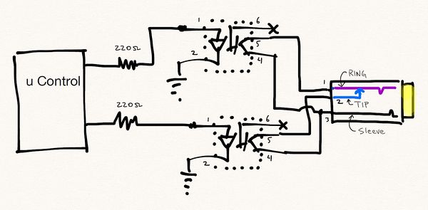
Interfacing with the camera utilized was done via a 3.5mm stereo jack which is connected to the camera N3 port. This is the standard interface of numerous Canon cameras. The 3.5mm stereo jack has three points of contacts on the connector, an outer ring, the middle ring and the tip. Shorting the middle ring to the outer ring triggers the cameras focus, while shorting the tip to the outer ring triggers the cameras shutter. Creating the connection for the required operations is done by way of using two optocouplers as switches. The order of operation for triggering the camera properly is to first engage the focus, engage the shutter then disengages both the shutter and focus. The circuit interface to the camera is displayed above.
The 220 ohm resistor has been selected to provide ~15mA (3.3v GPIO out from SJSU board divide by 220 ohm) going into 4N35 opto-coupler. The purpose of the opto-coupler is not only to transfer electrical signals between two isolated circuits by using light but also to serve as a protecting mechanism to prevent high voltage from going into the camera.
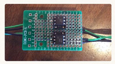
Picture of 4N35 in our hardware:
Hardware Interface
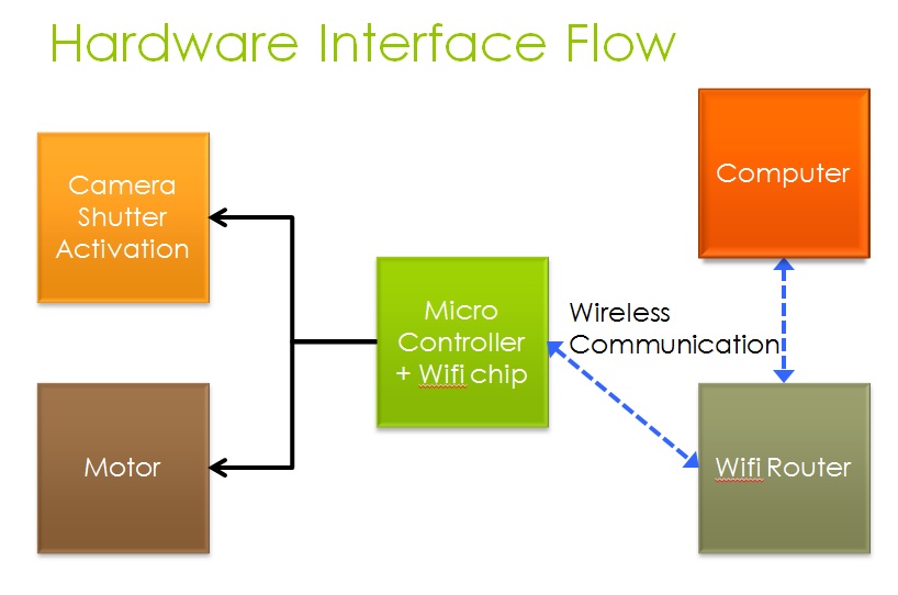
There are three main interfaces for our project:
1. GPIO: GPIO is used for camera activation. It takes two GPIO ports in order to activate the camera shutter. One GPIO to focus and and the other GPIO to open the shutter.
2. UART: Main communication between the wifi chip and our terminal task.
3. PWM output:
PWM, or Pulse Width Modulation, was used to control the 180-degree positional servo. The servo expects a train of pulses of varying widths. The pulses are repeated at a given period, typically set at 20 ms (50Hz). The width of the pulse is the code that signifies to what position the shaft should turn. The center position is usually attained with 1.3-1.5ms wide pulses, while pulse widths varying from 0.7-1ms will command positions all the way to the right (left), and pulse widths of 1.7-2ms all the way to the left (right). However, we found that the valid pulse widths were larger, ranging from 0.2 ms to 3.3 ms in our servo. Therefore, we expanded the range of pulse widths and converted the range into a degree range in software. The servo is connected to a 6V power supply and is controlled by PWM1 (P1.0)
Software Design
The software flow is detailed up top. The general flow has the user setting each variable (# of pictures to take, motor movement, shutter time, etc). After which, the program will automatically take pictures and move on their own until the required pictures have been taken.
As part of the flow process, there is a loop that is repeated in order to repeatedly take pictures and move the camera platform.
For our project, there are four different tasks: 1. Terminal Task: The terminal task is responsible for providing the input and output of the program. It is responsible for displaying data and modifying variables when the user wishes to change it. For example, the terminal task will allow the user to change the number of the pictures or time between pictures being taken.
As such, it contains the main code for displaying the different menus and the code to change variables according to user input.
2. Wifi Task: This sets the necessary parameters to connect to a router or another computer.
3. Camera Task: Main function of this task is to take pictures according to what the user inputted.
4. Motor Task: Provides the functionality to drive the motor to different positions.
Implementation
There are several design decisions made during the implementation of the project. We shall first go over the project design for each individual part and then describe the overall system integration.
1. As part of the project, we wanted to work with wireless communication because it is one of the most common methods for communication between two devices. That is why we picked the wi-fly chip for our bulb ramper. By using wifi, we can then expand the ways of interacting to the camera device such as a desktop computer or a cell phone.
2. For the camera interface, we used the N3 Canon Port for shutter activation. This was selected compared to USB interface, because it has a long history of usage and the design is simple to implement. We did not want to unnecessary complicate the design unless there was a need. If we went with USB, we would have been able to do "Live View" (stream the camera viewfinder to an external device) but decided against it. For our device, the purpose is to automate the picture taking process, by add "Live View", it does not bring any additional value for the user. For the N3 port, it is standard to use the N3 to Stereo Plug cable as the primary way to trigger the device. What was left was the translation of the signal between the SJSU board to the trigger signal. For that, we use the opto-decoupler. The main reason for the opto-decoupler is to protect the camera from high voltage by isolating the two sources.
3. Motor: For motor interface we used servomotors because of their dynamic performance: their ability to make fast speed and direction changes. In addition servomotors have the following characteristics that make them more reliable and desirable than stepper motors:
• Servomotors usually have a small size • Servomotors have a large angular force (torque) comparing to their size • Servomotors operate in a closed loop, and therefore are very accurate • Servomotors have an internal control circuit • Servomotors are electrically efficient – they required current is proportional to the weight of the load they carry.
Controlling servomotors is achieved by sending a single digital signal to the motor’s control wire. Therefore, we use the PWM, or Pulse Width Modulation signal to control the 180-degree positional servo.
Testing & Technical Challenges
There are several challenges in getting the project to work. Below are the list of the major ones that hopefully future students can avoid:
1) Have a good oscilloscope or at least, a volt meter. By seeing what is being sent out, it helps on the troubleshooting. In the beginning, the camera shutter wasn't being activated and it was hard to figure out what was happening without measuring what was coming out the chip. By having the equipment, it would have speed up troubleshooting process. The problem was that we put too high of a resistor inline with the optocoupler, so it did not have enough power for the LED to function and create a signal for the camera.
2) User Interface: For the user interface, it is important to plan how your project will interact with the user. We ended using a model where the user can select each digit and then increment each digit individually to modify the number quickly. Instead of click a specific key a hundred times, he just needs to select the third digit and change it to "1". We could have gone with the user inputting "100" directly but that would require input checks to make sure they did not input a letter or weird characters. Another item that gave us trouble was how to display the number so the user will know which digit was being selected. We choose to display the text in a blinking fashion so the user can track it. This was simulated by writing out the number, erase it, write the number again except skip the selected digit, erase it again and repeat from the start. For example, the following will be displayed (backspace omitted) 00000
0000
00000
0000
By writing five numbers, erase it, write four numbers, erase and repeat; it looks as the selected digit was blinking.
Here is an example of the third digit being selected (once again, the erase portion is omitted)
11111
11 11
11111
11 11
We then put a delay between each printf so the simulated blinking wasn't too quick.
3) The last of our challenges was making sure everything was working together. When we put all the tasks together, it took awhile to troubleshoot all the bugs. The scope of the programming bugs were not huge so we won't go into detail about it. However, the biggest asset for us when troubleshooting was using the printf function (or cout if using C++). By strategically placing printf functions, we can see which path the program took, what was inside a variable, and a whole multitude of other things. While we are aware there are debugging tools, the printf or cout has been the most reliable in terms of helping me figure out what the program was doing.
For example, if we expected only one of two conditions to occur (like an "if" statement), we would place a printf in each of them to make sure we weren't accidentally trigger a path we were suppose to take. In our project, we had an issue in the beginning with the motor increment factor. The motor wasn't incrementing in a set amount of steps, it just jumped from whatever starting position and went all the way to 180 on one giant step. To figure out what was happening, had the program print out what was in the motor increment variable each time the loop ran. This helped us realize it wasn't setting the variable in the way we thought it did.
Testing our project
We tested our project in several steps. We first divided the hardware portion between the both of us and each of us has to test the individual parts to make sure the part worked as expected. The camera shutter was tested with only the camera attached to the sjsu board; same thing for the motor. The wifly chip was also tested to see if it can communicate with another computer and so on.
After which, we incrementally added the hardware to the sjsu board piece by piece and doing a system level test. We first tested our project with the wi-fly board and the camera. Once that worked, we then added the motor to the mix. Each time, we had to try to break out project (input wrong values) so we can prevent any accidental fault conditions.
My Issue #1
The biggest issue with our bulb ramping project turned out to be the user interface. We had to consider several factors while trying to decide which interface to use.
1) Amount of time to work on the project 2) Usability of the settings 3) Code for adaptability in the future
Discussion of each point
1) The amount of time available to work on the project was a major factor in deciding to use the terminal interface. Since we were learning FREE RTOS, camera, wifi, & motor controls from scratch, it left us little time to work on the user interface. Our number one goal was to get the hardware system working nicely before moving to the refinement phase. In order to meet the project deadline, we choose to use the existing terminal task as a way to interact with the user.
2) We choose to use only a few selected keys as our main way of manipulating user parameters. The alternative, having the user input directly the number or pictures or open shutter time would have made the system slightly more complex and time consuming. This is because we would have to do a check on the input to make sure the input data was valid. Instead, by limiting the amount of options available, we had a bound on potential fault conditions the user might create.
3) Adaptability for the future is the most important point. This allows us to revisit the project in the future and make improvements. While coding the software, we had this in mind so that if we decided to add additional platforms (e.g. android support), the code can be modified easily. We wanted to avoid hard coding things in a specific way that would break the system if we had change it later on.
Other Issues
Motor There were some of difficulties at first in implementing the PWM driver. An oscilloscope was used to make sure that the appropriate signals were being sent out because the PWM pin with any dutycycle other than 100% or 0% will show a rising edge. This way it is easy to see whether or not a PWM signal really is being sent. A DMM was also used to check voltage levels to ensure that the appropriate voltage was being applied in each instance.
Wifi There was some difficulty in the beginning trying to get the wifly chip working. The main reason being was the toggle was set to UART 2 instead of UART 3 on the SJSU board.
Camera Control: In the initial breadboarding of the camera circuit, the camera was not triggering on the signal provided by the GPIO. This was primarily due to the 1000 ohm resistor used instead of the 220 ohm resistor in the latest version. The opto-coupler was not given enough power to transfer energy to the other side. By scaling back the resistance to 220 ohm, the camera responded to the camera shutter activation.
Conclusion
What we've learned from the project touched a wide variety of topics.
First, we've learned about FreeRTOS and there exists a programming shell for people to use in their multitasking applications. By learning FreeRTOS, it helps us learn more about the underlying function of the operating system and how to integrate it with our hardware. In the school setting, the program flow is pretty linear in terms of setting up a "main" function and go through in a line by line fashion. By learning about FreeRTOS, it helps expand our hands-on experience with multitasking oriented programming.
We've also learned about how the UART protocol functions. This was important in learning how to set up the port and using it communicate with other devices such as the wifi or terminal task. This really dovetails into us learning more about the hardware/software interface. Our experimentation with the motors and wi-fly was a fun and learning experience (when we got it to work...not so fun before that).
Last, we learned how important the user interface was. By coming up with fault scenarios with user input, we had to scale down our interface so that it will 1) meet schedule, 2) limit the possible errors that can be generated, & 3) still allow the user to reasonably input the camera parameters. Of all the tasks, I believe the user interface probably required more planning and implementation.
As a side note, the majority of the components used for this project were reclaimed materials. This not only kept the cost within reason but gave the project a unique one of a kind look. This method of construction was intentional, hopefully demonstrating that it is possible to create a useful and sophisticated device that utilizes current technology in an environmentally friendly fashion.
Ultimately the device functioned with greater precision and flexibility than had been originally anticipated. After several trial runs a satisfactory time-lapse film was produced. This can be viewed on the course Wiki designated for student projects. We hope to give a basis for others to expand and improve the project.
Project Video
2. Link to Timelapse created from project
Project Source Code
References
Acknowledgement
1. We would like to thank the Professor for helping out when we were stuck trying to code a specific portion of our software.
References Used
1. Opto-coupler wikipedia entry: [1]
2. Opto-coupler datasheet: [2]
Appendix
You can list the references you used.
