Difference between revisions of "S19: Hot Wheels"
Proj user13 (talk | contribs) (→Liquid Crystal Display) |
Proj user13 (talk | contribs) (→Software Design) |
||
| Line 763: | Line 763: | ||
[[File:MC_c.JPG|center|400px|Motor Controller Class]] | [[File:MC_c.JPG|center|400px|Motor Controller Class]] | ||
| + | |||
| + | |||
| + | In Periodic Init function, CAN1 is initialized at baudrate 100bps and TX/RX queues of size 10. In same function, to detect RPM rotation, an interrupt is enabled at port 2.5 at rising edge. | ||
| + | |||
| + | [[File:Periodic_Tasks.JPG|center|700px|Motor Controller Class]] | ||
=== Technical Challenges === | === Technical Challenges === | ||
Revision as of 08:46, 23 May 2019
Contents
Hot Wheels
Self Navigating RC car using CAN communication based on FreeRTOS.
Abstract
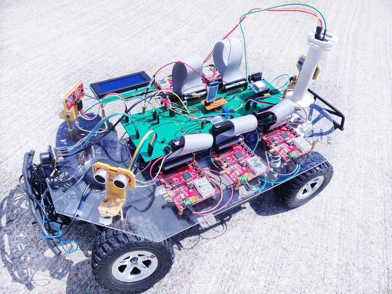
Hot Wheels is Self Navigating RC car using CAN communication based on FreeRTOS. While navigating to the destination, if car sees any kind of obstacle, it avoids that too. The RC car takes real time inputs and covert it into the data that can be processed to monitor and control to meet the desired requirements. In this project, we aim to design and develop a self-driving car that autonomously navigates from the current location to the destination which is selected through an Android application, avoiding all the obstacles in the path. The car comprises of 5 control units communicating with each other over the CAN Bus, each having a specific functionality that helps the car to navigate to its destination successfully.
Introduction
The project was divided into 5 modules:
| Sensor Controller | This module detects obstacles in the driving path with the help of ultrasonic sensors. |
|---|---|
| Motor Controller | This controller drives the DC motor and Servo in the car and controls the speed of the car. |
| Geographical Controller | This module assists the car in navigating to a destination with the help of location details provided by GPS and the orientation(bearing and heading angle) provided by the compass. |
| Android Application | Application developed on Android-based phones to communicate with car. Destination coordinates,Start and Stop signals are send to car using this application.The Application also displays sensor values in real time for debugging purposes. |
| Bluetooth Controller | The controller uses Bluetooth to communicate with an Android application on the Android phone. Destination coordinates are provided by this module. The Bluetooth module also displays important |
| Master Controller | This module collects inputs from all other modules and controls the motor. It is responsible for system health monitoring, Obstacle avoidance and navigation to the destination. |
Team Members & Responsibilities
Gitlab Project Link - [1]
- Master Controller
- Kailash Chakravarty
- Sensor Controller
- Rishabh Sheth
- Motor Controller
- Kriti Hedau
- Tahir Rawn
- Geographical Controller
- Harmeen Joshi
- Nandini Shankar
- Communication Bridge Controller & Android Application
- Swanand Sapre
- Aquib Mulani
- Code Review & Commit Approvers
- Rishabh Sheth
- Nandini Shankar
- Kailash Chakravarty
Schedule
| Week# | Date | Task | Status | Completion Date |
|---|---|---|---|---|
| 1 | 02/12/19 |
|
|
|
| 2 | 02/17/19 |
|
|
|
| 3 | 02/26/19 |
|
|
|
| 4 | 03/05/19 |
|
|
|
| 5 | 03/12/19 |
|
|
|
| 6 | 03/19/19 |
|
|
|
| 7 | 03/26/19 |
|
|
|
| 8 | 04/02/19 |
|
|
|
| 9 | 04/09/19 |
|
|
|
| 10 | 04/16/19 |
|
|
|
| 11 | 04/23/19 |
|
|
|
| 12 | 04/30/19 |
|
|
|
| 13 | 05/07/19 |
|
|
|
| 14 | 05/14/19 |
|
|
|
| 15 | 05/22/19 |
|
|
|
Parts List & Cost
| Item# | Part Desciption | Vendor | Qty | Cost |
|---|---|---|---|---|
| 1 | RC Car | Traxxas | 1 | $250.00 |
| 2 | CAN Transceivers MCP2551-I/P | Microchip [2] | 8 | Free Samples |
| 3 | Graphics LCD module | 1 | From Preet | |
| 4 | Bluetooth(HC-05) | 1 | HiLetgo | $9.00 |
Printed Circuit Board
Design
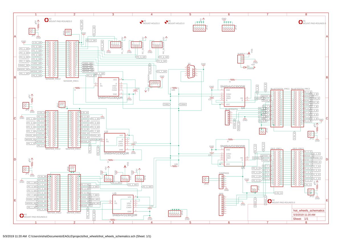
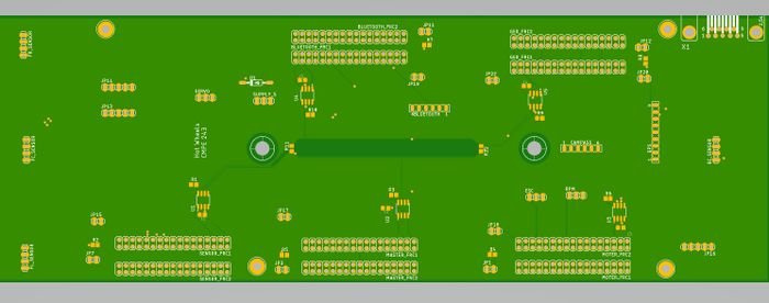
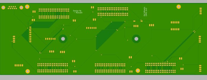
We designed the custom PCB using DipTrace Software in which we implemented connections for all the controller modules(SJOne Board LPC1758) all communicating/sending data via CAN bus. The data is sent by individual sensors to the respective controllers. GPS and Compass are connected to Geographical Controller. RPM sensor, DC and Servo Motors are connected to Motor Controller. Ultrasonic and Lidar are connected to Sensor Controller. LCD is connected to Motor Controller. Bluetooth is connected to Bridge Controller. CAN Bus is implemented using CAN Transceivers MCP2551 terminated by 120Ohms; with PCAN for monitoring CAN Debug Messages and Data.
Power Supply
We implemented separate power modules for LIDAR and remaining modules of the PCB. The micro USB mini B supplies 5V to LIDAR Motor and Scanner (max current rating estimated @ 1A). Another power is supplied through USB 2.0 Type A connector with a rating of 5V@2A. Since GPS requires 3.3V, we have used a linear regulator REG1117-3.3. All the parts are through-hole components.
Fabrication
PCB was sent to fabrication to JLCPCB China which provided PCB with MOQ of 5 with the lead time of 1 week. We implemented 2 layers of PCB with most of the parts in top layer. We implemented rectangular header connector for SJOne boards, RPM sensor, DC & Servo Motor and GPS modules on the bottom layer.
Challenges
There were 2 iterations of this board. The first one was designed without validation and had problems with orientation of the SJOne board header & pin connections. We also need to change the header for LCD since it was having different pitch.This design lacked several necessary power connections and was limited by functionality. These problems were fixed in the 2nd iteration.
Bill Of Materials
|
HARDWARE INTEGRATION PCB | ||||
|---|---|---|---|---|
|
PART NAME |
PART MODEL |
QUANTITY |
COST PER UNIT (USD) | |
| CAN Transceiver | SN65HVD230-SOIC8 | 5 | $2.38 | |
| Buzzer | BUZZER-CEM-1203 | 2 | $0.83 | |
| Buzzer Switch | MMBT2222A-TP | 1 | $0.15 | |
| 3.3V Regulator | LDL1117S33R | 1 | $0.46 | |
| 5V Regulator | LM1085IS-12/NOPB-ND | 1 | $2.36 | |
| Red LED | LED-0603 | 1 | $-.-- | |
| Diode | Diode | 1 | $0.32 | |
| 100uF Capacitor | SMD 603 100uF Capacitor | 1 | $0.44 | |
| 10uF Capacitor | SMD 603 10uF Capacitor | 1 | $0.44 | |
| 4.7uF Capacitor | SMD 603 4.7uF Capacitor | 1 | $0.44 | |
| 1uF Capacitor | SMD 603 1uF Capacitor | 1 | $0.44 | |
| 10K Resistor | SMD 603 10K Resistor | 1 | $0.44 | |
| 5.1K Resistor | SMD 603 5.1K Resistor | 1 | $0.44 | |
| 1K Resistor | SMD 603 1K Resistor | 1 | $0.44 | |
CAN Communication
<Talk about your message IDs or communication strategy, such as periodic transmission, MIA management etc.>
Hardware Design
<Show your CAN bus hardware design>
DBC File
Gitlab link to DBC file [3]
VERSION ""

NS_ :
	BA_
	BA_DEF_
	BA_DEF_DEF_
	BA_DEF_DEF_REL_
	BA_DEF_REL_
	BA_DEF_SGTYPE_
	BA_REL_
	BA_SGTYPE_
	BO_TX_BU_
	BU_BO_REL_
	BU_EV_REL_
	BU_SG_REL_
	CAT_
	CAT_DEF_
	CM_
	ENVVAR_DATA_
	EV_DATA_
	FILTER
	NS_DESC_
	SGTYPE_
	SGTYPE_VAL_
	SG_MUL_VAL_
	SIGTYPE_VALTYPE_
	SIG_GROUP_
	SIG_TYPE_REF_
	SIG_VALTYPE_
	VAL_
	VAL_TABLE_

BS_:

BU_: MASTER GEO APP MOTOR SENSOR DBG

BO_ 1 START_STOP: 1 APP
 SG_ BRIDGE_START_STOP : 0|8@1+ (1,0) [0|1] "cmd" MASTER

BO_ 2 MOTOR_COMMANDS: 1 MASTER
 SG_ MOTOR_COMMANDS_stsp : 0|8@1+ (1,0) [0|1] "" MOTOR

BO_ 36 APP_HEARTBEAT: 1 APP
 SG_ APP_HEARTBEAT_signal : 0|8@1+ (1,0) [0|255] "" MASTER

BO_ 37 GEO_HEARTBEAT: 1 GEO
 SG_ GEO_HEARTBEAT_signal : 0|8@1+ (1,0) [0|255] "" MASTER

BO_ 38 MOTOR_HEARTBEAT: 1 MOTOR
 SG_ MOTOR_HEARTBEAT_cmd : 0|8@1+ (1,0) [0|0] "" MASTER

BO_ 17 MASTER_SPEED_STEER_VAL: 3 MASTER
 SG_ MASTER_SPEED_STEER_VAL_speed : 0|8@1+ (0.1,0) [0.0|2.0] "%dc" MOTOR
 SG_ MASTER_SPEED_STEER_VAL_steer : 8|8@1+ (0.1,0) [10.0|20.0] "%dc" MOTOR
 SG_ MASTER_SPEED_STEER_VAL_dir : 16|8@1+ (1,0) [0|2] "" MOTOR

BO_ 108 BLUETOOTH_LAT_LONG: 8 APP
 SG_ GPS_Latitude : 0|31@1+ (0.000001,-90.000000) [-90|90] "degrees" GEO,MASTER
 SG_ GPS_Longitude : 32|32@1+ (0.000001,-180.000000) [-180|180] "degrees" GEO,MASTER

BO_ 39 ULTRA_CMD: 5 SENSOR
 SG_ ULTRA_CMD_Front_Left : 0|9@1+ (1,0) [2|400] "" MASTER,APP
 SG_ ULTRA_CMD_Front_Center : 9|9@1+ (1,0) [2|400] "" MASTER,APP
 SG_ ULTRA_CMD_Front_Right : 18|9@1+ (1,0) [2|400] "" MASTER,APP
 SG_ ULTRA_CMD_Back_Center : 27|9@1+ (1,0) [2|400] "" MASTER,APP


BO_ 195 GEO_NAV_DATA: 6 GEO
 SG_ GEO_TELECOMPASS_compass : 0|13@1+ (0.1,0) [0|365.0] "" MASTER,APP
 SG_ GEO_TELECOMPASS_bearing_angle : 13|12@1+ (0.1,0) [0|360.0] "" MASTER,APP
 SG_ GEO_TELECOMPASS_distance : 25|12@1+ (0.1,0) [0|0] "" MASTER,APP
 SG_ GEO_TELECOMPASS_destination_reached : 37|1@1+ (1,0) [0|1] "" MASTER,APP

BO_ 214 GEO_CURRENT_COORD: 8 GEO
 SG_ GEO_CURRENT_COORD_LAT : 0|32@1+ (0.000001,0) [36.000000|38.000000] "degrees" MASTER,APP
 SG_ GEO_CURRENT_COORD_LONG : 32|32@1+ (0.000001,-123) [-123.000000|-120.000000] "degrees" MASTER,APP

BO_ 517 MOTOR_SPEED_STEER_DBG: 3 MOTOR
 SG_ DBG_STEER_VAL_speed : 0|8@1+ (0.1,0) [13.5|16.5] "%dc" MASTER,DBG
 SG_ DBG_SPEED_STEER_VAL_steer : 8|8@1+ (0.1,0) [10.0|20.0] "%dc" MASTER,DBG
 SG_ DBG_SPEED_STEER_VAL_dir : 16|8@1+ (1,0) [0|1] "" MASTER,DBG

BO_ 505 GEO_DEBUG_CMPS_CALIB_STATUS: 1 GEO
 SG_ GEO_DEBUG_CMPS_CALIB_STATUS_System : 0|2@1+ (1,0) [0|3] ""
 SG_ GEO_DEBUG_CMPS_CALIB_STATUS_Magneto : 2|2@1+ (1,0) [0|3] ""
 SG_ GEO_DEBUG_CMPS_CALIB_STATUS_Accelero : 4|2@1+ (1,0) [0|3] ""
 SG_ GEO_DEBUG_CMPS_CALIB_STATUS_Gyro : 6|2@1+ (1,0) [0|3] ""

BO_ 508 GEO_DEBUG_DEST_COORD: 8 GEO
 SG_ GEO_DEBUG_DEST_COORD_Latitude : 0|31@1+ (0.000001,-90.000000) [-90|90] "degrees"
 SG_ GEO_DEBUG_DEST_COORD_Longitude : 32|32@1+ (0.000001,-180.000000) [-180|180] "degrees"

CM_ BU_ DRIVER "The driver controller driving the car";
CM_ BU_ MOTOR "The motor controller of the car";
CM_ BU_ SENSOR "The sensor controller of the car";
CM_ BO_ 100 "Sync message used to synchronize the controllers";

BA_DEF_ "BusType" STRING ;
BA_DEF_ BO_ "GenMsgCycleTime" INT 0 0;
BA_DEF_ SG_ "FieldType" STRING ;

BA_DEF_DEF_ "BusType" "CAN";
BA_DEF_DEF_ "FieldType" "";
BA_DEF_DEF_ "GenMsgCycleTime" 0;

BA_ "GenMsgCycleTime" BO_ 100 1000;
BA_ "GenMsgCycleTime" BO_ 500 100;
BA_ "GenMsgCycleTime" BO_ 101 100;
BA_ "GenMsgCycleTime" BO_ 400 100;
BA_ "GenMsgCycleTime" BO_ 200 100;
BA_ "FieldType" SG_ 100 DRIVER_HEARTBEAT_cmd "DRIVER_HEARTBEAT_cmd";
BA_ "FieldType" SG_ 500 IO_DEBUG_test_enum "IO_DEBUG_test_enum";


VAL_ 100 DRIVER_HEARTBEAT_cmd 2 "DRIVER_HEARTBEAT_cmd_REBOOT" 1 "DRIVER_HEARTBEAT_cmd_SYNC" 0 "DRIVER_HEARTBEAT_cmd_NOOP" ;
VAL_ 500 IO_DEBUG_test_enum 2 "IO_DEBUG_test2_enum_two" 1 "IO_DEBUG_test2_enum_one" ;
Sensor ECU
Sensor Selection
Design & Implementation
Hardware Design
Software Design
Algorithm
Motor Controller
Group Members
Design & Implementation
Hardware Design
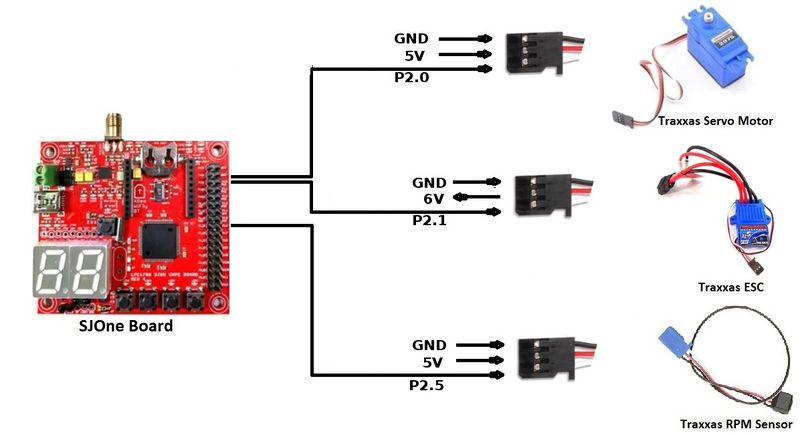
| Pin Number | Pin Function |
|---|---|
| P0.0 | CAN RX |
| P0.1 | CAN TX |
| P2.0 | Servo Motor |
| P2.1 | Electronic Speed Controller (ESC) |
| P2.5 | RPM Sensor |
Hardware Specifications
ESC and DC Motor
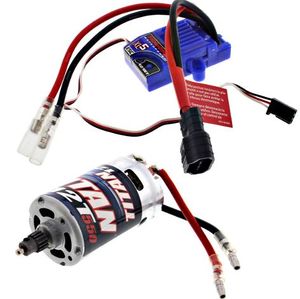
The Traxass Slash 4x4 has XL-5 Electronic Speed Controller (ESC) and Titan 12T DC Motor installed in it. The ESC is powered by LiPo Battery which further controls the DC motor. The ESC comes with the feature of calibrating the DC motor using the EZ set button that is present on ESC. It comes with three modes
- Sport mode (100% Forward, 100% Brakes, 100% Reverse)
- Training mode (100% Forward, 100% Brakes, No Reverse)
- Racing mode (50% Forward, 100% Brakes, 50% Reverse)
For our project we used Sport mode because we needed full capability of the motor for uphills and rough terrains. Also we used our ESC in Low-Voltage Detection activated mode. In order to know more about ESC profiles, Battery modes and how to calibrate them, refer to Traxxas official link here [4].
| Wires on (ESC) | Description | Wire Color Code |
|---|---|---|
| (+)ve | Positive Terminal | RED |
| (-)ve | Negative terminal | BLACK |
| Wires on (ESC) | Description | Wire Color Code |
|---|---|---|
| (+)ve | Connects to (+)ve of DC Motor | RED |
| (-)ve | Connects to (-)ve of DC Motor | BLACK |
| (+)ve | Connects to (+)ve of Battery | RED |
| (-)ve | Connects to (-)ve of Battery | BLACK |
| P2.0 (PWM1) | PWM Signal From SJOne | WHITE |
| VCC | 6 Volts (OUTPUT) | RED |
| GND | Ground | BLACK |
Servo Motor
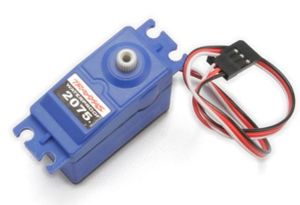
Servo Motor is responsible for steering the car. Traxxas Slash 4x4 has Servo Motor 2075 pre-installed in it. It controls the front two tires of the car.
| Pin No. (SJOne Board) | Function | Wire Color Code |
|---|---|---|
| P2.1 (PWM2) | PWM Signal | WHITE |
| VCC | 5V (INPUT) | RED |
| GND | Ground | BLACK |
RPM Sensor
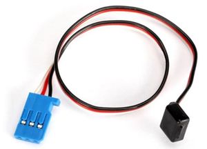
RPM sensor is used to calculate speed of the car. A magnet is placed inside the spur gear with the help of magnet holder and every time a tire completes one rotation, RPM sensor detects a pulse. RPM sensor it self is placed in the gear cover. In order get the RPM Sensor working, following Telemetry items from Traxxas are required
- Traxxas RPM Sensor 6522
- Traxxas Magnet Holder 6538
- Traxxas Gear Cover 6537
To install these, there is very detailed step by step tutorial by Steve Jones (Cstoneav) on Youtube which can be found here [5]
| Pin No. (SJOne Board) | Description | Wire Color Code |
|---|---|---|
| P2.5 (PWM6) | GPIO (INPUT) | WHITE |
| VCC | 5V (INPUT) | RED |
| GND | Ground | BLACK |
Hardware Interface
Software Design
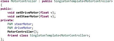
For Motor Controller module, we made a singleton class for it. Some groups from our batch and from previous batches faced an issue that PWM object was going out of scope and they weren't able to get it run. We adapted this implementation from start, learning from experiences of our seniors of this course and never faced any issue regarding this. This class would only have one object, which initializes PWM objects for both Servo and DC in it's constructor.
In Periodic Init function, CAN1 is initialized at baudrate 100bps and TX/RX queues of size 10. In same function, to detect RPM rotation, an interrupt is enabled at port 2.5 at rising edge.
Technical Challenges
Geographical Controller
<Picture and link to Gitlab>
Hardware Design:
Module Interface:
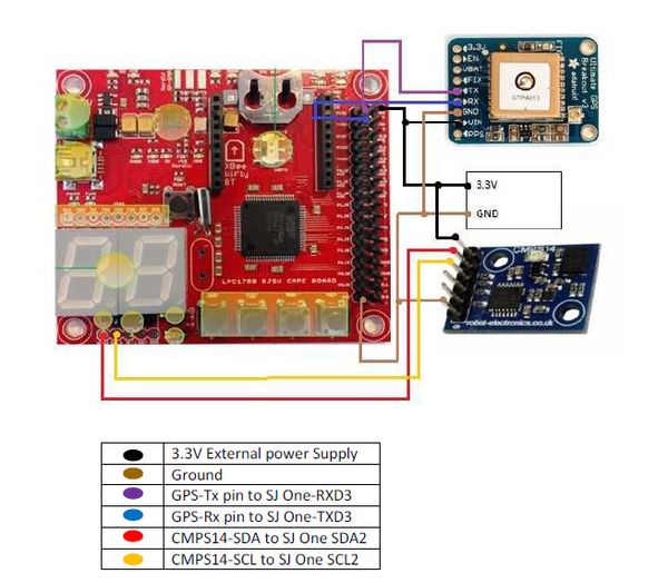
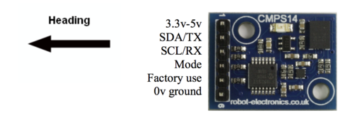
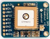
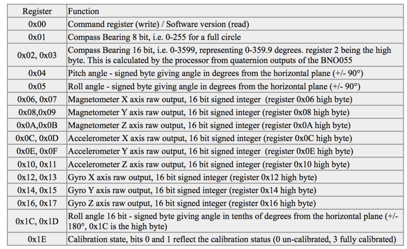
The GEO module primarily consists of two independent hardware modules: the GPS module and the compass module. The GPS module provides the current location of the car as it moves and the compass module provides the heading angle of the car with respect to true north. For the GPS module, we are using Adafruit's "Ultimate GPS Breakout V3" and for the compass module, we are using "CMPS14" module from Robotshop. CMPS14 module uses I2C interface to connect with the SJ-One board whereas, the GPS module is interfaced to SJ-One using UART.
Module Selection:
Selecting the appropriate module for both the compass and the GPS sensing were difficult decisions. We initially ordered "GPS - Readytosky Ublox NEO-M8N GPS Module" from Amazon as it came with a stand and an inbuilt compass module. This would have been cheaper as we would save money on the compass module. However, we later found out that the inbuilt compass values were not reliable enough and the GPS in this module was not original Ublox. Original Ublox GPS has an inbuilt flash memory to update its firmware for GPS calibration. We would thus have to rely on the factory calibration for the GPS. After considering all this, we decided to move to better modules as navigation was key for our project's success.
Compass modules are very sensitive to magnetic interference. We selected CMPS14 module as our compass as it has commands to dynamically check the calibration status of the module at runtime. We mapped this calibration status value to the 7-segment display on the SJ-one board which proved to be very useful in detecting magnetic interference across the campus and take decisions accordingly. Note however that CMPS14 does not return the current gyro calibration status. This is a bug which is mentioned in its data sheet. For the GPS module, we went with Adafruit's Ultimate GPS breakout module as it is known for its reliable GPS values.
CMPS14 Commands:
CMPS14 Start Calibration Process
To start the compass calibration, write the following to the command register 0x98, 0x95, 0x99 with a 20 millisecond delay after each byte. You can then send the setup byte to the command register. It takes the form:
CMPS14 End Calibration Process
To end the calibration and store the updated calibration profile in CMPS14, write the following byte sequence to the command register with a 20 millisecond delay after each of the three bytes: 0xF0, 0xF5, 0xF6
Switch 4 dedicated for this purpose.
CMPS14 Erase Calibration Profile
To erase the stored calibration profile in CMPS14, write the following byte sequence to the command regiester with a 20 millisecond delay: 0xE0, 0xE5, 0xE2 . Switch 3 dedicated for this purpose.
Software Design
<List the code modules that are being called periodically.>
1. Calibrating Compass module
   The compass module was not giving stable values on default calibration.

   The compass north changed every time the module powered off.

   The compass value would change after a full 360-degree rotation.

   The compass value moved up on tilting the module.
Technical Challenges and Solutions
1. Calibrating Compass Module
   The compass module was not giving stable values on default calibration.

   The compass north changed every time the module powered off.

   The compass value would change after a full 360-degree rotation.

   The compass value moved up on tilting the module.
Solution:
   Step 1: Keep the compass stable on the ground to calibrate the gyro sensor.

   Step 2: Now, randomly move the module to calibrate the magnetometer.

   Step 3: After this, tilt the compass module in all directions and slowly move the module 360-degrees clockwise and anti-clockwise
           to calibrate the accelerometer.

   Make sure the calibration status of the respective in-built sensor reaches the maximum value of 3 on each of the above steps.

   Note: Compass is best calibrated in a non-magnetic environment. To check the magnetism in any area, use a mechanical (magnetic)compass.

   Note: There are underground electrical lines spread throughout the university which cause magnetic interference in the compass module.
         We found 10th street parking, 6th floor to be a good spot for testing and calibrating compass and GPS module.
2. Compass Calibration Unreliable
After calibrating the compass, the calibration status was changing at runtime due to magnetic interference from the ground and shaking of the car.
Solution:
   Mapped system calibration status to on-board 7-segment display to keep track of the compass calibration at run-time and provided dedicated switches
   to start calibration, end calibration and erase calibration profile. This allowed us to perform instant re-calibration of the compass
   if the calibration is affected.

   Also provided dedicated switch to add offset to the compass value.
   This enabled us to set true North according to the mechanical compass in high magnetic interference areas.
3. Magnetic Interference from Motor
   Unlike interference from the ground and underground electrical lines, interference from car motors was causing the compass value to

   increment even when the car was not moving. This interference increased as the car speed increased.
Solution:
   To avoid this interference, we magnetically shielded the car's DC motor. To achieve this, we simply covered the motor with aluminum foil.
   This significantly reduced the magnetic interference to the compass from the motor.

   Note: There is no known material that blocks magnetic fields without itself being attracted to the magnetic force. Magnetic fields can only be redirected,
   not created or removed. The magnetic field cannot be completely blocked. Magnetic shielding can be done by any material which absorbs magnetism
4 Unreliable GPS lock
Communication Bridge Controller & LCD
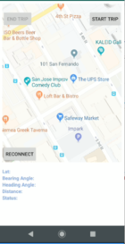
User communicates with the car through the Communication Bridge Controller. This module consists of the LPC1758 communicating with the Android application on the phone via Bluetooth.The user selects the final destination on the google map to which the car should navigate, through an android application. LCD is used to display the recorded values of the ultrasonic sensors, the current latitude and longitude values from gps, bearing and heading angle from the compass for the car. Along with that these values can be seen on Android application also.
Hardware Design
Bluetooth
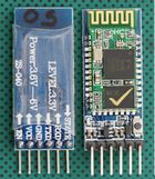
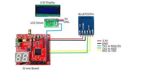
The HC-05 Bluetooth module was used to communicate the Android application in the Android phone with the car.This module is based on the Cambridge Silicon Radio BC417 2.4 GHz Bluetooth Radio chip. This is a complex chip which uses an external 8 Mbit flash memory.It includes the Radio and Memory chips, 26 MHz crystal, antenna and RF matching network. The right section of the Bluetooth Board has connection pins for power and signals as well as a 5V to 3.3V Regulator, LED, and level shifting. The Bluetooth from mobile phone communicated with the micro-controller through the Bluetooth module interfaced to it dedicated to receive the messages from the phone, parse those messages and convert them into appropriate data type that was transmitted to the expected receiver through the CAN Bus.
- HC-05 PinOut :
- EN: In case brought HIGH before power is applied, forces AT Command Setup Mode
- VCC: +3.3V Power
- GND: Ground
- TXD: Serial Transmit pin connected to RXD2 of SJOne board
- RXD: Serial Receive pin connected to TXD2 of SJOne board
- STATE: States if connected or not
- LED Blinking signals:
- if flashing RED fast: ready to pair
- if flashing RED slow: paired and connected
Liquid Crystal Display
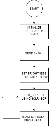
A 20x4 LCD(CM 204-1) with LCD driver by SJValley Engineering is used for accessing the LCD through UART. The driver and LCD are soldered directly to avoid any loose connection. To power up LCD 5V supply is given from common 5V source which is coming from ESC (6V) and converting it to 5V using buck-boost. As soon as the LCD is powered on, it is initialize to baudrate of 38500 and 0xF0 command is send. After 0xF0 is sent, the data can be transmitted using UART. Before that two commands are send to set brightness level and clear screen. If you are getting some junk values, make sure that the baud rate is set correct and check the soldering.
Software Design
Bluetooth
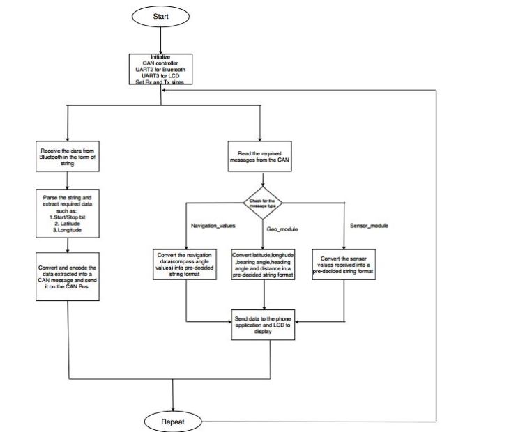
A special format for the strings received was used to make extracting of the important aspects such as start/stop command, latitude and longitude of the destination. Similarly, we also kept a specific format for the string that was to be transmitted to the mobile application which made data parsing and displaying in the android application easy . The specific formats that we chose are as shown below:
- Format for the string received from android application: ~start/stop@latitude!longitude#
 ~ denotes the start of the string and also the start of the start/stop variable
 @ denotes the start of latitude value
 ! denotes the start of longitude and the end of latitude values
 # denotes the end of the entire string
 example: ~1@37.337897!-121.885623#
- Format for the string transmitted to android application: ~Sensor values@latitude!longitudeCcompass_value^bearing angle$distance#
 ~ denotes start of the string
 @ denotes start of latitude
 ! denotes start of longitude
 C denotes start of the compass_values
 ^ denotes start of bearing angle
 $ denotes start of distance
 # denotes end of the string
 example: ~L300R200F150B200@37.337897!-121.885623C140.12^310.87$26#
Keeping such dedicated formats made data parsing convenient and easy to convert and process the data further ahead.
Liquid Crystal Display
| Command | Description |
|---|---|
| $BLIGHT:100 | To set brightness to 100(full) |
| $CLR_SCR | To clear screen |
| $GOTO:3:4 | To move cursor to particular position (col:row) |
At first the LCD is initialize to baud rate and 0xF0 is send. Then Brightness is set and screen is clear. This is done only for the first time. After this sensor values are displayed on LCD through UART and our screen is getting updated after every 1 second and this value will continue for total of 3 seconds and then gps and compass values are shown similarly by clearing the screen and in this way it goes on continuously until power off.
Technical Challenges
- Connection between Application and Module is not stable. Over a medium-long range, the application gets disconnected with HC-05 module.
Solution: We used "Reconnect Button" on our Android application to re-establish Bluetooth socket connection instead of re-opening the application.
- When multiple cars are around and if they are using the same HC-05 module since the pairing password for the HC-05 module is same for everyone, the application ceased to connect to the Bluetooth due to interference from Bluetooth of other Android applications.
Solution: Change the password of the Bluetooth module using the AT commands using an Arduino.
- Getting junk values when LCD is power ON and only 2 lines were displaying.
Solution: Soldering issue possibly or driver also, so better test it before soldering to get clear idea. In our project we change our LCD and the second one works well.
Android Application
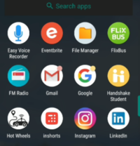
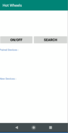
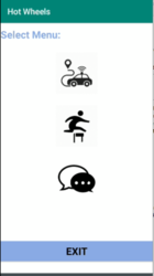
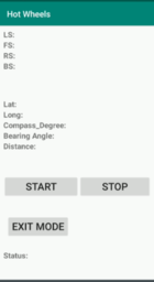
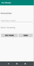
User Communicates with the car using Android application.We have three modes on application namely
1.Self-Drive Mode
2.Obstacle Detection Mode
3.Communication mode.
UI of Application
Technical Challenges
- Connection between Application and Module is not stable. Over a medium-long range, the application gets disconnected with HC-05 module.
Solution: We used "Reconnect Button" on our Android application to re-establish Bluetooth socket connection instead of re-opening the application.
References for Android Application
Master Module
<Picture and link to Gitlab>
Hardware Design
The Master controller only has the connections to the CAN bus apart from power supply. Below diagram describes the connections.
Software Design
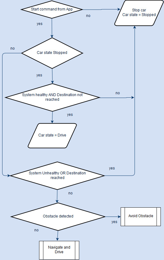
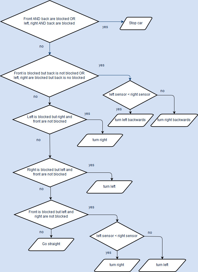
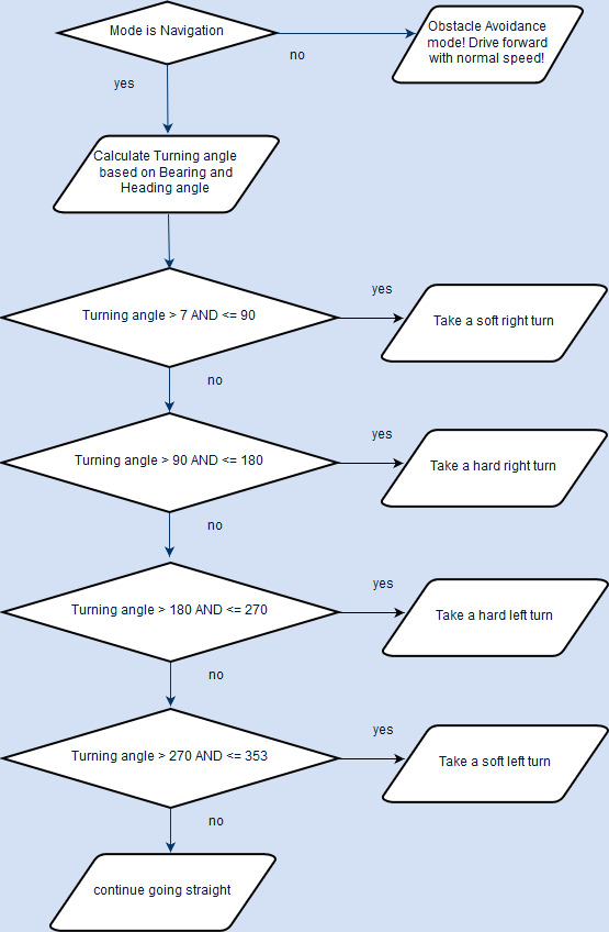
- The Master control unit is the heart of the Self driving car as it takes all the critical decisions based on inputs it receives from the other control units like App, Sensor, Geo and drives outputs which is the Motor control Unit.
- The Master control unit mainly performs Navigation of the car to the selected destination and Obstacle avoidance as and when they come in the car's way.
- For navigation to the destination through numerous checkpoints, the bearing angle, heading angle and the distance to destination is provided by the GEO control. The App control provides the start and stop command.
- The Sensor control unit provides the ultrasonic sensor values of the 4 sensors regarding obstacle avoidance.
- The Master control unit algorithms - Navigation and Obstacle avoidance are run @25Hz. The detailed flowcharts are shown below.
Technical Challenges
Improper Unit Testing
Problem : It was tedious to tune the proximity thresholds for the 4 sensors for proper obstacle avoidance, because it involved changing them, build them, flash them and test again and again till we get fine tuned results. This was time and effort consuming.
Resolution : I placed a CAN debug message in the code to write directly into the threshold variables, via PCAN dongle and bussmaster whenever I want. So basically I change the thresholds anytime within seconds and immediately test.
Conclusion
We were able to navigate our RC car from current destination of the car to the destination chosen through the android application successfully . The car was also able to avoid obstacles in its path throughout the journey to the marked destination.The project helped us gain a working knowledge of CAN bus and communication, interfacing various components such as motors, GPS, Bluetooth and ultrasonic sensors along with some knowledge regarding pulse width modulation (PWM), UART, I2C. This course and project also gave us a deep understanding of FreeRTOS, Android, Unit testing and Git. It taught us the important aspect of team work, coordination and surely taught us the importance of proper planning and hard work.Overall, it was a superb experience enriched with knowledge and hands on experience that molded us into better than we were before.
Project Video
Project Source Code
Advise for Future Students
<Bullet points and discussion>
Acknowledgement
We would like to thank our professr, Preetpal Kang for designing such an amazing course and including the project of self-navigating car in the coursework. He was always there to guide and push us to achieve our goal of implementing a self-navigating car successfully. We would also like to thank the ISA member,Pratap for providing his insights and feedback after demos and motivating us to do well. We would also like to thank all the members of the other teams who selflessly coordinated and helped us,forgetting all their differences when in need.
References
- Professor Preetpal Kangs lecture notes and slides of CMPE 243, Computer Engineering, San Jose State University
- HC-05 Datasheet
- Traxxas - RC Car & Forum
