Difference between revisions of "S19: CANT Bus"
Proj user4 (talk | contribs) (→Team Members & Responsibilities) |
Proj user4 (talk | contribs) (→Team Members & Responsibilities) |
||
| Line 22: | Line 22: | ||
=== Team Members & Responsibilities === | === Team Members & Responsibilities === | ||
* Kevin Chan | * Kevin Chan | ||
| − | ** IR sensors (Proximity), Compass | + | ** IR sensors (Proximity), Compass (Localize), GPS (Localize), Distance Vector (Localize), Code Review |
* Khrysta Finch | * Khrysta Finch | ||
** Chassis, Driver (Driver), LCD display (Comms), Schematic, Telemetry (Comms) | ** Chassis, Driver (Driver), LCD display (Comms), Schematic, Telemetry (Comms) | ||
Revision as of 08:10, 23 May 2019
Contents
Grading Criteria
- How well is Software & Hardware Design described?
- How well can this report be used to reproduce this project?
- Code Quality
- Overall Report Quality:
- Software Block Diagrams
- Hardware Block Diagrams
- Schematic Quality
- Quality of technical challenges and solutions adopted.
[C]ompile [A]nother [N]on-[T]rivial Bus
Abstract
Design and implement an autonomous car to navigate to a destined location chosen by the user using a phone application. The user will set gps coordinates via an Android application while the current location is processed. The RC car should be able to use these coordinates to navigate itself to the destined location avoiding obstacles and providing useful data on the way. Several objectives need to be completed in order for the RC car to function properly: integrate proximity sensors, gps, compass, lcd screen, motor driver board, esp32 communication, hall sensor, and overall integration in order for the RC car to be able to determine where it is, the speed it's going, and the environment around it to successfully navigate to the final destination.
Introduction
The purpose of this project was to convert a RC car into a self driving vehicle that can navigate itself to a destination sent via an Android mobile app. To achieve this, the project was divided into 7 modules: Avoidance, Motor, Master Driver, Localize, Comms, and Android Application. The Avoidance module contains 8 IR sensors that allow the car to see the world around it. This module finds objects and measures the distance between it and the object. Motor controls a brushed motor which drives the car at various speeds and a servo to turn the car. In addition, Motor also contains a hall effect sensor that keeps track of the cars speed. Localize tells the car where it is in relation to where it needs to go. It contains a GPS and Compass to provide current coordinates and heading. Comms houses the wireless device that talks to the the mobile app as well as an LCD display to show various car data such as speed and destination. The mobile app is where the user can enter GPS coordinates as a destination point, or alter the current destination with a way-point. Lastly, the Driver receives the data from all modules and decides how the car shall react. In order to complete these modules basic knowledge of I2C, UART, SPI, and CAN bus protocols, gpio control, PWM control, phone application development, and pathing algorithms was required. While each peripheral in the modules used their own form of communication, each of the modules was connected using the CAN bus protocol.
Team Members & Responsibilities
- Kevin Chan
- IR sensors (Proximity), Compass (Localize), GPS (Localize), Distance Vector (Localize), Code Review
- Khrysta Finch
- Chassis, Driver (Driver), LCD display (Comms), Schematic, Telemetry (Comms)
- Andrew Javier
- Hall Sensor (Motor), Wireless communications via esp32(Comms), GPS (Localize), Chassis
- Aaron Lee
- GPS (Localize), Pathing Algorithm (Comms)
- Jonathan Rojas
- Motor (Motor), Servo (Motor), Motor driver board (Motor), hall sensor (Motor), Cable Management, Chassis
- Vijay Vanapalli
- GPS (Localize), Wireless communications via esp32(Comms), Mobile app (Comms)
- Nelson Wong
- Team Leader, Driver (Driver), Telemetry (Comms), PCB/Schematic, Chassis, Mobile App (Comms), Power, Code Review
Source Code
Modules
- Driver
- Proximity
- Motor
- Localize
- Vijay Vanapalli
- Aaron Lee
- Andrew Javier
- Kevin Chan
- Comms
- Andrew Javier
- Vijay Vanapalli
- Khrysta Finch
- Android Application
- Vijay Vanapalli
- Testing Team
- Kevin Chan
- Nelson Wong
Schedule
Show a simple table or figures that show your scheduled as planned before you started working on the project. Then in another table column, write down the actual schedule so that readers can see the planned vs. actual goals. The point of the schedule is for readers to assess how to pace themselves if they are doing a similar project.
| Week# | Start Date | End Date | Task Description | Status | Completion Date |
|---|---|---|---|---|---|
| 1 | 3/4 | 3/10 |
|
Complete | |
| 2 | 3/11 | 3/17 |
|
||
| 3 | 3/18 | 3/24 |
|
||
| 4 | 3/25 | 3/31 |
|
||
| 5 | 4/1 | 4/7 |
|
||
| 6 | 4/8 | 4/14 |
|
||
| 7 | 4/15 | 4/21 |
|
||
| 8 | 4/22 | 4/28 |
|
||
| 9 | 4/29 | 5/5 |
|
||
| 10 | 5/6 | 5/12 |
|
Parts List & Cost
| Item# | Part Desciption | Vendor | Qty | Cost |
|---|---|---|---|---|
| 1 | RC Car | Traxxas | 1 | $250.00 |
| 2 | CAN Transceivers MCP2551-I/P | Microchip [1] | 8 | Free Samples |
Printed Circuit Board
We used the online tool Upverter to create our schematic and design the final PCB board. Both schematic and board can be found on Upverter using the link below.
CAN Communication
CAN BUS Messages
The DBC file that was used to generate our CAN messages can be found below. Each message has a priority ID assigned to it that is used by the CAN protocol to see which device to listen to first in cases of bus arbitration; the lower the ID number the higher priority it has. In our case, the message with the highest priority at 10 is KILL_MOTOR. Since we are using LiPO (Lithium Polymer) batteries, the desire to disconnect all power for the battery depleted was high on the list. Should the car be driving at that time, the KILL_MOTOR_cmd shuts off the motor immediately, allowing us to catch up to the car and swap out batteries. The KILL_MOTOR_REMOTE message follows the KILL_MOTOR message in priority. This is simply a redundancy we built in to have the message delivered to the mobile app and notifying us that the battery is low.
The priority decreases from there with HEARTBEAT from the Driver being the next highest. Since the Driver doesn't send many messages and it's there to collect data from all the other modules, it needs to let the others know it's still available. MOTOR_CMD follows as we wanted the car to move as quickly as possible, which leads to AVOIDANCE_LIDAR as the next highest. Knowing when we were in close proximity to an object is key to making sure we don't run into it. Note that while this message has "LIDAR" as part of the name, this is legacy nomenclature from when we initially had LIDAR for the car. They are now IR sensors.
GPS, Compass, and Speed were assigned the lowest priorities. While knowing where we are in relation to where we are going is important, it was less demanding that knowing if we are about to hit something or if the battery was depleted. Overall, this choice in priority has served well in providing a functional autonomous car.
Hardware Design
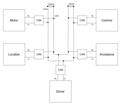
Each of the modules are connected to a CAN transceiver via transmit and receive lines. The transceivers themselves are connected together through their CAN high and low pins (CANH/CANL) with each of those lines terminating with a 120 ohm resistor.
CAN DBC File
BS_:
BU_: COMMS DRIVER LOCALIZE MOTOR AVOIDANCE

BO_ 10 KILL_MOTOR: 1 DRIVER
 SG_ KILL_MOTOR_cmd : 0|8@1+ (1,0) [0|0] "" MOTOR,COMMS

BO_ 11 KILL_MOTOR_REMOTE: 1 COMMS
 SG_ KILL_MOTOR_cmd : 0|8@1+ (1,0) [0|0] "" DRIVER

BO_ 100 DRIVER_HEARTBEAT: 1 DRIVER
 SG_ DRIVER_HEARTBEAT_cmd : 0|8@1+ (1,0) [0|0] "" LOCALIZE,COMMS,AVOIDANCE,MOTOR

BO_ 101 MOTOR_CMD: 2 DRIVER
 SG_ MOTOR_CMD_steer : 0|3@1+ (1,-1) [-1|1] "degrees" MOTOR
 SG_ MOTOR_CMD_drive : 8|4@1+ (1,-2) [-2|5] "" MOTOR

BO_ 102 DRIVER_STATUS: 1 DRIVER
 SG_ DRIVER_STATUS_enum : 0|3@1+ (1,0) [0|0] "" COMMS

BO_ 200 AVOIDANCE_LIDAR: 8 AVOIDANCE
 SG_ LIDAR_f_right : 0|8@1+ (1,0) [0|0] "cm" DRIVER
 SG_ LIDAR_f_m_right : 8|8@1+ (1,0) [0|0] "cm" DRIVER
 SG_ LIDAR_f_middle : 16|8@1+ (1,0) [0|0] "cm" DRIVER
 SG_ LIDAR_f_m_l : 24|8@1+ (1,0) [0|0] "cm" DRIVER
 SG_ LIDAR_f_left : 32|8@1+ (1,0) [0|0] "cm" DRIVER
 SG_ LIDAR_b_right : 40|8@1+ (1,0) [0|0] "cm" DRIVER
 SG_ LIDAR_b_middle : 48|8@1+ (1,0) [0|0] "cm" DRIVER
 SG_ LIDAR_b_left : 56|8@1+ (1,0) [0|0] "cm" DRIVER

BO_ 201 DESIRED_VECTOR: 8 LOCALIZE
 SG_ DESIRED_HEADING : 0|32@1+ (0.1,0) [0|360.0] "degrees" DRIVER,COMMS
 SG_ DESIRED_DISTANCE : 32|32@1+ (0.00001,0) [0|0] "km" DRIVER,COMMS

BO_ 300 LOCALIZE_GPS: 8 LOCALIZE
 SG_ GPS_STATUS : 0|8@1+ (1,0) [0|0] "" DRIVER,COMMS
 SG_ GPS_TX_LATITUDE : 8|24@1+ (0.000001,37.000000) [37.000000|38.000000] "degrees" DRIVER,COMMS
 SG_ GPS_TX_LONGITUDE : 32|32@1- (0.000001,-122.000000) [-122.000000|-121.000000] "degrees" DRIVER,COMMS

BO_ 301 LOCALIZE_IMU: 8 LOCALIZE
 SG_ IMU_STATUS : 0|8@1+ (1,0) [0|0] "" DRIVER,COMMS
 SG_ IMU_COMPASS : 8|12@1+ (0.1,0) [0|360.0] "degrees" DRIVER,COMMS

BO_ 302 SPEED: 8 LOCALIZE
 SG_ SPEED_kph : 0|16@1- (0.001,0) [-5|10] "kph" COMMS,DRIVER

BO_ 303 LOCALIZE_IMU_DEBUG: 8 LOCALIZE
 SG_ IMU_COMPASS_X : 0|10@1- (1,0) [-200|200] "" DBG
 SG_ IMU_COMPASS_Y : 10|10@1- (1,0) [-200|200] "" DBG

BO_ 400 MOTOR_STATUS: 1 MOTOR
 SG_ MOTOR_STATUS_data : 0|8@1+ (1,0) [0|0] "" COMMS,DRIVER

BO_ 500 SET_WAYPOINT: 8 COMMS
 SG_ SET_WAYPOINT_LAT : 0|24@1+ (0.000001,37.331610) [37.331610|37.340132] "degrees" LOCALIZE,DRIVER
 SG_ SET_WAYPOINT_LONG : 24|24@1- (0.000001,-121.886025) [-121.886025|-121.876412] "degrees" LOCALIZE,DRIVER

BO_ 501 SET_STATUS: 1 COMMS
 SG_ SET_STATUS_enum : 0|2@1+ (1,0) [0|0] "" DRIVER

BO_ 700 DRIVER_DEBUG: 8 DRIVER
 SG_ VEL_ARR : 0|32@1+ (1,0) [0|0] "" AVOIDANCE

BO_ 701 AVOIDANCE_DEBUG: 8 AVOIDANCE
 SG_ AVOIDANCE_COUNT : 0|32@1+ (1,0) [0|0] "" DRIVER

BO_ 702 MOTOR_DEBUG: 4 MOTOR
 SG_ MOTOR_SPEED_DBG : 0|32@1+ (0.0001,0) [0|0] "ms" DRIVER

BO_ 704 TACHOMETER_DEBUG: 8 LOCALIZE
 SG_ TACHOMETER_DBG : 0|16@1- (0.001,0) [-5|10] "kph" COMMS,DRIVER

CM_ BU_ DRIVER "The driver controller driving the car";
CM_ BU_ MOTOR "The motor controller of the car";
CM_ BU_ LOCALIZE "The localization controller of the car";
CM_ BU_ AVOIDANCE "The collision avoidance controller of the car";
CM_ BU_ COMMS "The wireless comms and telemetry controller of the car";
CM_ BO_ 100 "Sync message used to synchronize the controllers";
CM_ BO_ 501 "0: stop, 1: ready, 2: navigate, 3: skip/next"
BA_DEF_ "BusType" STRING ;
BA_DEF_ BO_ "GenMsgCycleTime" INT 0 0;
BA_DEF_ SG_ "FieldType" STRING ;
BA_DEF_DEF_ "BusType" "CAN";
BA_DEF_DEF_ "FieldType" "";
BA_DEF_DEF_ "GenMsgCycleTime" 0;
BA_ "GenMsgCycleTime" BO_ 500 100;
BA_ "GenMsgCycleTime" BO_ 100 1000;
BA_ "GenMsgCycleTime" BO_ 101 100;
BA_ "GenMsgCycleTime" BO_ 400 100;
BA_ "GenMsgCycleTime" BO_ 200 100;
BA_ "FieldType" SG_ 102 DRIVER_STATUS_enum "DRIVER_STATUS_enum";
BA_ "FieldType" SG_ 103 SET_STATUS_enum "SET_STATUS_enum";
BA_ "FieldType" SG_ 500 DBC_TEST1_enum "DBC_TEST1_enum";
BA_ "FieldType" SG_ 100 DRIVER_HEARTBEAT_cmd "DRIVER_HEARTBEAT_cmd";
VAL_ 102 DRIVER_STATUS_enum 7 "STOP" 6 "FWD_R" 5 "REV_R" 4 "REV_M" 3 "REV_L" 2 "FWD_L" 1 "FWD_M" 0 "IDLE" ;
VAL_ 103 SET_STATUS_enum 1 "GO" 0 "STOP" ;
VAL_ 500 DBC_TEST1_enum 2 "DBC_TEST1_enum_val_two" 1 "DBC_TEST1_enum_val_one" ;
VAL_ 100 DRIVER_HEARTBEAT_cmd 2 "DRIVER_HEARTBEAT_cmd_REBOOT" 1 "DRIVER_HEARTBEAT_cmd_SYNC" 0 "DRIVER_HEARTBEAT_cmd_NOOP" ;
Proximity ECU
<Picture and link to Gitlab>
The Proximity ECU was also known as the Avoidance module and can be found on GitLab here. It's sole purpose is to monitor the environment around the car and take measurements of objects that break the threshold.
Hardware Design
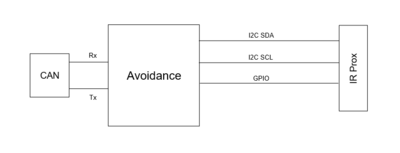
Avoidance contains eight VL53L0X infrared sensors for obstacle detection that utilizes the I2C interface. The sensors measure a distance in centimeters with a maximum range of 2 meters with 1 millimeter resolution. The VL53L0X sensor used in the car was purchased pre-attached to a breakout board where the voltage was stepped down from 3.3V to 2.8V. The XSHUT pin on the sensor acts as an enable where they were wired to GPIO pins on the SJOne board. For the car, there were a total of 8 sensors used: 5 in the front, 3 in the back. The sensors come preassigned to an address of 0x52 but can be reassigned to a different address. The table for sensor address assignment and GPIO are seen below.
| Sensor Position | GPIO pin | Slave Address |
|---|---|---|
| Front Right | P2_2 | 0x54 |
| Front Middle Right | P0_30 | 0x61 |
| Front Middle | P2_1 | 0x56 |
| Front Middle Left | P0_29 | 0x63 |
| Front Left | P2_0 | 0x58 |
| Back Right | P2_5 | 0x5A |
| Back Middle | P2_4 | 0x5C |
| Back Left | P2_3 | 0x5E |
| Default | none | 0x52 |
Power for the sensors came from the car power supply regulated for 3.3V instead of from the SJOne board. The problem and solution of assignment of the I2C address can be seen below in the software design. The block diagram for this module can be found below. Note that for brevity, not all 8 proximity sensors are shown. Each sensor is connected in the same manner each with its own dedicated GPIO pin.
Software Design
<List the code modules that are being called periodically.>
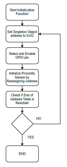
For the software design, a C++ library was ported over from Pololu along with configuration of the library to work with the SJOne Board. A C wrapper was written to allow it to be unit tested and included in our periodic_callbacks.c file. There were difficulties with having a singleton object for 8 sensors that created conflict. This was resolved by having a table of addresses, that the singleton object would select and reassign its address with to sweep through the sensor addresses. The configuration of the reassignment of addresses also took careful consideration.
The initialization function for these sensors followed the flowchart below of how to reassign the addresses of each sensor even when they all start with the initialized with the same address. The process would first enable the first sensor with XSHUT using the GPIO pin, the singleton object would set its address to the default address of 0x52. The function would then initialize it depending on the which GPIO function was enable to the addresses seen above in the table and write to the device register to change its slave address. After initializing was completed for one sensor, the sensor would stay enabled, but the singleton object would be reset back to 0x52 to set the next sensor.
To collect and store data from each sensor, a data structure was created to be placed in a CAN message. A function was created where it would again sweep the address space of the address table, and store the data to its respective location in the data structure. This occurs every 20 Hz, where a CAN message is broadcasted on the bus for DRIVER to use.
Technical Challenges
The only issues with the proximity sensors came from using a library provided by Pololu that used a singleton object. To address this issue, a table of addresses was created where the singleton object would sweep the table of addresses to retrieve data from each sensor. The singleton object would reassign its own address from the table to access each sensor individually. The process described in the software design was also used for retrieving data from each sensor.
Motor ECU
Hardware Design
Software Design
Motor
Periodic Init
- Initializes CAN, servo PWM (50Hz), motor driver board PWM (100Hz), interrupt for hall sensor, and speed calibration
1Hz Task
- Used to check the state of CAN and reset.
10Hz Task
- Receive CAN message for Motor Control
- Send Motor Status
- Send Motor Speed
Technical Challenges
- Motor and Servo Frequencies
- Hall Sensor Speed Determination
Motor and Servo Frequencies
<Problem Summary>
- Single frequency for PWM on SJone board
Using PWM on the SJOne board only allows for one PWM frequency on all the PWM pins. For Motor, we required two different frequencies (motor (100Hz) and servo (50Hz)). We solved this by using a motor driver board using i2c to create a second PWM frequency.
- Fluctuating PWM Frequency
The PWM for MOTOR varied by a few Hz depending on the environment causing the duty cycle to control the motor to change. We set the frequency to be 100Hz, but varied between 98.7Hz. This caused the dutycycle to change from 70% to 80% to initiate the motor.
<Problem Resolution>
- Single frequency for PWM on SJone board
We solved this by using a motor driver board using i2c to create a second PWM frequency.
- Fluctuating PWM Frequency
In order to be able to deal with any situation and environment the RC car will be in we created a function to manually calibrate the first speed by increasing the dutycycle by 1% using push buttons and automatically incrementing the higher speeds with it.
Hall Sensor Speed Determination
<Problem Summary>
- Creating a secure mount with enough magnets
Using PWM on the SJOne board only allows for one PWM frequency on all the PWM pins. For Motor, we required two different frequencies (motor (100Hz) and servo (50Hz)). We solved this by using a motor driver board using i2c to create a second PWM frequency.
- Fluctuating PWM Frequency
The PWM for MOTOR varied by a few Hz depending on the environment causing the duty cycle to control the motor to change. We set the frequency to be 100Hz, but varied between 98.7Hz. This caused the dutycycle to change from 70% to 80% to initiate the motor.
<Problem Resolution>
- Single frequency for PWM on SJone board
We solved this by using a motor driver board using i2c to create a second PWM frequency.
- Fluctuating PWM Frequency
In order to be able to deal with any situation and environment, the RC car will be in we created a function to manually calibrate the first speed by increasing the dutycycle by 1% using push buttons and automatically incrementing the higher speeds with it.
Localize ECU
Hardware Design
LSM303
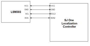
The LSM303 was selected as the compass for the final product. The LSM303 is a digital compass that contains an acceleration sensor and temperature sensor onboard. It uses the I2C communication protocol and can be power via a 5V or 3.3V power source. For this sensor, the SJOne board directly powered the compass. The clock rate for the slave clock was set to 100 KHz. The compass requires calibration which will be described in the both the software and technical challenges.
NEO-6M GPS
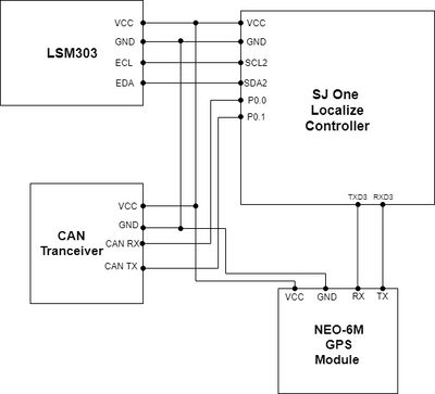
The geographical/localization controller (SJOne board) was connected to a compass and GPS module.
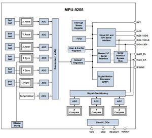
The compass that we are using for this project is an MPU-9255 which consist of an accelerometer, gyrometer, and three-axis magnetometer. For our purpose, only the magnetometer is used to find the direction of where the car is facing, which connects to the geographical controller via I2C. As you can see in the block diagram from this module, we will only need to connect to the AUX_DA (EDA) and AUX_CL (ECL), from the compass, to the SDA2 and SCL2, respectively. The connections to the auxiliary ports of this module will bypass the accelerometer and gyrometer completely.
The GPS module that was selected was a Ublox Neo-6M module. The GPS communicates with the geographical controller via UART.
Software Design
LSM303
For the LSM303, the compass required an initialization function to set all the registers. The slave address for writing to the LSM303 is 0x3D and to read from the registers is 0x3C. The data for the compass can be read from 6 8-bit registers, where X Y and Z axis are divided into high and low registers. The data is represented in two’s-complement where the conversion needed to be done after merging the two bytes together. As per the datasheet, the X axis is registers 3 and 4, where register 3 is the high byte and 4. The same goes for the Z axis which is registers 5 and 6, and Y is registers 7 and 8. After the raw coordinates are obtained, the calibration goes into effect.
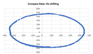
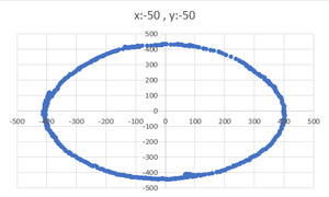
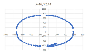
To calibrate the compass, the X and Y points were plotted while negating the Z axis. The Z axis was negated because the calibration of the compass requires that the compass be perfectly level. A sample of points were collected, and the plot can be seen below.
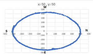
To calibrate the compass, offsets were added such that the circle is centered at 0,0. The calibration was then added, and it looks like the plot below.
An additional feature that needed to be added was closing the gaps created from having the compass close to the car. Shifting was needed to close the circle when there were gaps in the calibration caused from the electronics of the car.
After the points have been calibrated, an angle was formed from the point in relation to 0,0. The points go counter clockwise it goes in the order of North - 0, East - 90, South - 180, West - 270. The X and Y points were outputted to the CAN bus as a debug message and the compass direction was used for pathing.
NEO-6M GPS
For the compass, the get_data() modules is being called periodically in the c_periodic_callbacks file in the 100 Hz function. We want the sensor data to be sent to the CAN bus at a 20 Hz frequency, which is implemented by using an if-statement and a modulo 5 on the count variable which results to updated sensor value at 20 Hz: if(count % 5 == 1){}
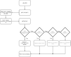
The get_data() function will return a structure called 'compass_t'. In this structure, it groups three data values for the heading of the compass, the x and y-raw value of the magnetic flux density as a signed 16-bit integer and the calculated heading, which returns as a float. When calling the get_data() functions, it retrieves the X and Y-raw values of the magnetic flux density and then calculates the heading as shown in the diagram below.
Technical Challenges
- Calibration of LSM303
- The problem with the LSM303 and all digital compasses, is there is a lot of interference with magnetic fields in buildings that requires calibration for different environments. In addition, compasses do not come pre-calibrated as the strength of the North pole varies depending on location. To resolve this issue, we calibrated the compass in various locations. Our final calibration that we used and kept was the furthest away from any potential magnetic fields. Our selected location was on the top floor of the engineering building that was away from any lab rooms or elevators.
<Bullet or Headings of a module>
Unreliable GPS lock
- Obtaining Coordinates
- When attempting to obtain coordinates, the GPS module took several minutes in order to connect to a satellite and return coordinates. This process took more time if the GPS module was in a building or in a non-open area.
- Information from the GPS module was delivered at a rate of 1 Hz. When this information arrived, there were several possibilities such as $GPGGA, $GPGSV, and $GPRMC.
- Coordinates were only obtained when $GPRMC messages were sent and it yielded an Active (A) coordinate.
- There was no way to manipulate the GPS module to only send $GPRMC messages.
- Parsing Data
- All messages are appended with a new line "\r\n" at the end allowing it to be perfect candidates for the UART gets function. To help with consistency, the gets function was only called when there were characters in the queue to prevent the read from being timed out.
- Occasionally, some messages become cut off and merged with the next message. This skewed readings as commas were used to separate different sections of the data, including instances where $GPRMC was sent.
- To save resources, coordinates were only calculated when $GPRMC messages were sent with an (A) status message. This data is presented in a degree, minute, second format as opposed to the decimal format used by the SJOne and the mobile application. As a fail safe, converted coordinates were only saved and sent if the value yielded a latitude between 37 and 38 degrees and a longitude between -122 and -121 degrees.
Comms ECU & LCD
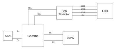
The Comms module source code includes the code for the ESP32 WiFi device and LCD display. Below is the block diagram for this module's connections.
Hardware Design
ESP32 WiFi Module
LCD Display
The LCD display used is a 2.4" TFT display made by Adafruit. This display uses either the 8-bit or SPI protocol to transfer data. For this application, the SPI protocol was used in combination with an additional Data/Command line to distinguish between command packets (pulled low) or data packets (pulled high). The display is then connected via a controller that determines what pixels to activate and color. The controller itself uses the I2C protocol to communicate with the Comms board.
Software Design
<List the code modules that are being called periodically.>
ESP32 WiFi Module
LCD Display
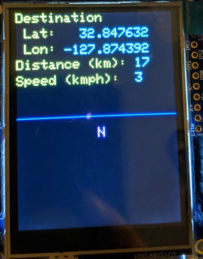
The main elements we wanted to be able to see on the car were speed and destination. Destination is displayed in Lat/Long decimal degree coordinates and speed is in kilometers per hour. In addition, we also show the distance between our car and the destination and our current heading from due north. Due to the complexity of the display, each pixel requires about 7 bytes to activate, the possibility of overrunning the scheduler was high. As such, a controller was inserted to perform the actual data transfer to write pixels. The Comms module simply tells the controller what to update, via I2C, from the 1Hz periodic function. To make writing pixels a little easier, the Adafruit GFX Library was used to create fonts, lines, and the triangles used to mimic a compass.
There are five basic functions used to update the display, four are used to set values to a data struct and the fifth sends the data over I2C:
- set_display_waypoint() - packages the latitude and longitude destination struct values as a C-string
- set_display_speed() - packages the car's current speed struct value in a C-string.
- set_display_distance() - packages the distance remaining between the car and the destination in a C-string
- set_display_arrow() - selects which heading arrow the display should draw: N, S, E, W, NW, NE, SW, or SE
- updateDisplay() - sends the full struct that has been prepared by the above functions over I2C
Technical Challenges
<Bullet or Headings of a module>
Insane Bug
<Problem Summary> <Problem Resolution>
Driver Module
<Picture and link to Gitlab>
Hardware Design
Software Design
<List the code modules that are being called periodically.>
Technical Challenges
<Bullet or Headings of a module>
Improper Unit Testing
<Problem Summary> <Problem Resolution>
Mobile Application
<Picture and link to Gitlab>
Hardware Design
Software Design
<List the code modules that are being called periodically.>
Technical Challenges
<Bullet or Headings of a module>
Wifi Link Reliability
<Problem Summary> <Problem Resolution>
Conclusion
<Organized summary of the project>
<What did you learn?>
Project Video
Project Source Code
https://gitlab.com/cant-bus/cant-bus
Advise for Future Students
<Bullet points and discussion>
