Difference between revisions of "F17: FoxP2"
Proj user5 (talk | contribs) (→Bridge Controller) |
Proj user17 (talk | contribs) (→Hardware Design) |
||
| (195 intermediate revisions by 2 users not shown) | |||
| Line 1: | Line 1: | ||
| − | === | + | == FOXP2 == |
| − | |||
| − | |||
| − | |||
| − | |||
| − | |||
| − | |||
| − | |||
| − | |||
| − | |||
| − | |||
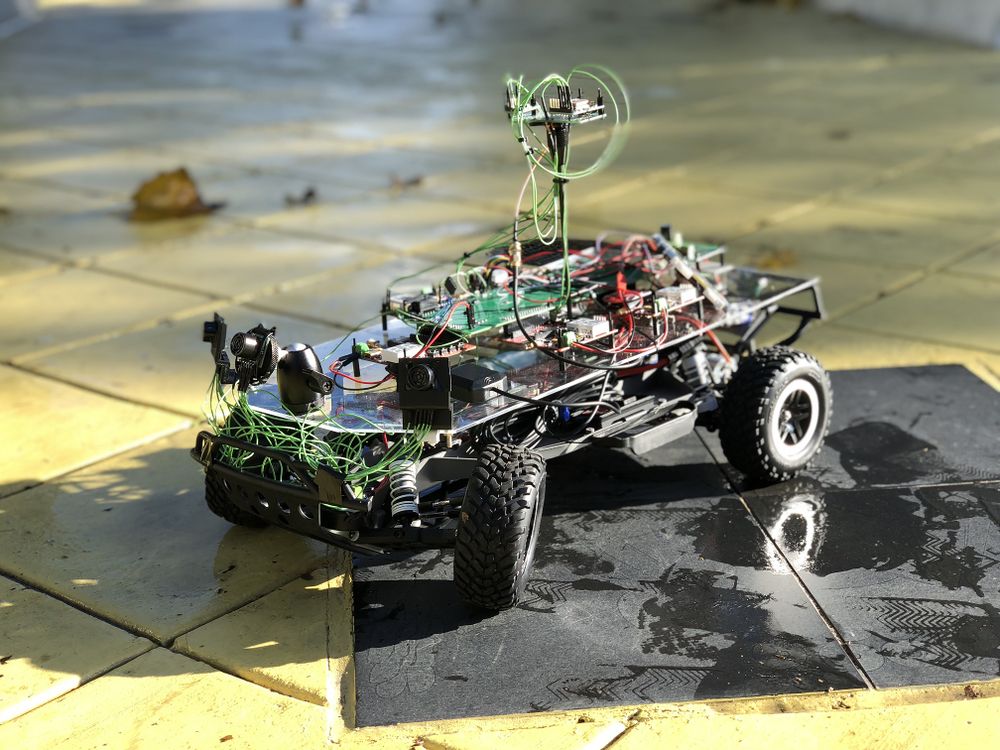
| − | + | [[File:Cmpe243_F17_FOXP2_CAR01.jpg|1000px|middle|FOXP2 autonomous car]] | |
| − | [[File: | + | |
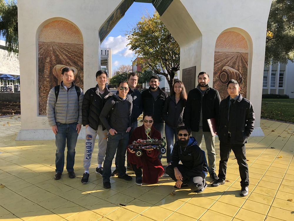
| + | [[File:Cmpe243_F17_FOXP2_Group_Pic.jpg|1000px|middle|FOXP2 Group]] | ||
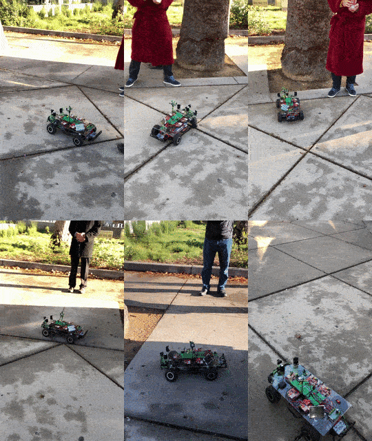
| + | [[File:CMPE243_F17_FOXP2_demo_gif.gif|300px|Demo day challenge]] | ||
== Abstract == | == Abstract == | ||
| Line 20: | Line 12: | ||
== Objectives & Introduction == | == Objectives & Introduction == | ||
| − | + | ||
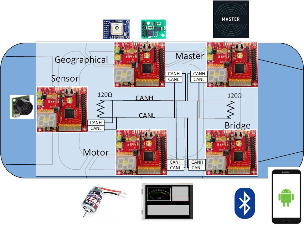
| + | Our objective in this project was to create a fully autonomous car that would receive a GPS destination coordinate and would be able to reach there despite any obstacles around it. We used 5 SJ One boards to communicate each other over the CAN bus where each one of the boards would be responsible for system critical responsibilities. We had 5 boards that took care of the following features: | ||
| + | |||
| + | * Gateway: Master controller that would receive data from GPS and Sensor modules and decide on next actions. Based on that it will control the Motor module to maneuver the car | ||
| + | * Sensor: Detects obstacles at 45, 90 and 135 degrees and sends data back to Gateway module | ||
| + | * Motor: Controls the front and back wheels according to Gateway module's commands. Also shows system critical data on LCD | ||
| + | * GPS: Uses GPS and compass to detect current location of the car. Also gets the destination and checkpoints from Bridge to send direction requests to Gateway | ||
| + | * Bridge: Communicates with Android App through external Bluetooth HW to coordinate locations/destinations between the App and the GPS module | ||
=== Team Members & Responsibilities === | === Team Members & Responsibilities === | ||
| Line 31: | Line 30: | ||
* '''Jason Tran''' | * '''Jason Tran''' | ||
| − | ** Sensor IO | + | ** Infrastructure |
| − | ** | + | ** Sensor IO Implementation |
| + | ** Testing | ||
* '''[https://www.linkedin.com/in/ahsanu/ Ahsan Uddin]''' | * '''[https://www.linkedin.com/in/ahsanu/ Ahsan Uddin]''' | ||
| + | ** Code structure and quality | ||
** Git Admin | ** Git Admin | ||
| − | ** Motor Control | + | ** Motor Control |
| − | * '''Yuyu Chen''' | + | * '''[https://www.linkedin.com/in/ychen2809/ Yuyu Chen]''' |
** Geographical Implementation | ** Geographical Implementation | ||
** Bridge Support | ** Bridge Support | ||
| Line 46: | Line 47: | ||
** Bridge Implementation | ** Bridge Implementation | ||
| − | * '''Rabeel Elahi''' | + | * '''[https://www.linkedin.com/in/rabeel-elahi-155217a0/ Rabeel Elahi]''' |
| − | ** Master Controller Implementation. | + | ** Master/Gateway Controller Implementation. |
| + | ** Object Detection Implementation. | ||
* '''Sophia Quan''' | * '''Sophia Quan''' | ||
| − | ** LCD interface | + | ** LCD interface |
| − | |||
* '''Michael Jaradah''' | * '''Michael Jaradah''' | ||
| Line 63: | Line 64: | ||
== Schedule == | == Schedule == | ||
| − | |||
{| class="wikitable" | {| class="wikitable" | ||
| Line 101: | Line 101: | ||
Android & Bridge: 10/21/2017 | Android & Bridge: 10/21/2017 | ||
| + | Sensors: 10/21/2017 | ||
| + | |||
| + | Master: 10/21/2017 | ||
| + | |||
| + | Geographical: 10/21/2017 | ||
| + | |||
| + | Motor: 10/21/2017 | ||
|- | |- | ||
! scope="row"| 2 | ! scope="row"| 2 | ||
| Line 114: | Line 121: | ||
Master: Start the design of the master controller for all IO. | Master: Start the design of the master controller for all IO. | ||
| Completed | | Completed | ||
| − | + | Completed | |
Completed | Completed | ||
| Line 120: | Line 127: | ||
Completed | Completed | ||
| − | + | Completed | |
| | | | ||
Geographical: 10/21/2017 | Geographical: 10/21/2017 | ||
| + | |||
| + | Motor: 10/21/2017 | ||
| + | |||
| + | Sensors: 10/21/2017 | ||
| + | |||
| + | Master: 10/21/2017 | ||
Android & Bridge: 10/28/2017 | Android & Bridge: 10/28/2017 | ||
| Line 142: | Line 155: | ||
Android & Bridge: Completed | Android & Bridge: Completed | ||
| − | + | Motor: Completed | |
| + | |||
| + | Sensors: Completed | ||
| + | |||
| + | Master: Completed | ||
| | | | ||
Geographical: 10/28/2017 | Geographical: 10/28/2017 | ||
| Line 148: | Line 165: | ||
Android & Bridge: 11/04/2017 | Android & Bridge: 11/04/2017 | ||
| + | Master: 10/28/2017 | ||
| + | |||
| + | Sensors: 10/28/2017 | ||
| + | |||
| + | Motor: 10/28/2017 | ||
|- | |- | ||
! scope="row"| 4 | ! scope="row"| 4 | ||
| Line 169: | Line 191: | ||
Master: Completed | Master: Completed | ||
| + | Motor: Completed | ||
| + | |||
| + | Sensors: Completed | ||
| | | | ||
Geographical: 11/04/2017 | Geographical: 11/04/2017 | ||
| + | |||
| + | Motor: 11/04/2017 | ||
| + | |||
| + | Sensors: 11/04/2017 | ||
| + | |||
| + | Master: 11/04/2017 | ||
Android & Bridge: 11/11/2017 | Android & Bridge: 11/11/2017 | ||
| Line 186: | Line 217: | ||
Master: Testing of Signals, CAN, and behavior of the vehicle. | Master: Testing of Signals, CAN, and behavior of the vehicle. | ||
| | | | ||
| − | Geographical: | + | Geographical: Completed |
| + | |||
| + | Motor: Completed | ||
| + | |||
| + | Sensors: Completed | ||
Android & Bridge: Completed | Android & Bridge: Completed | ||
| − | Master: | + | Master: Completed |
| | | | ||
Geographical: 11/11/2017 | Geographical: 11/11/2017 | ||
Android & Bridge: 11/18/2017 | Android & Bridge: 11/18/2017 | ||
| + | |||
| + | Motor: 11/11/2017 | ||
| + | |||
| + | Sensors: 11/11/2017 | ||
| + | |||
| + | Master: 11/11/2017 | ||
|- | |- | ||
! scope="row"| 6 | ! scope="row"| 6 | ||
| Line 206: | Line 247: | ||
Sensors: Improve filtering algorithm. Develop proof of concept for TOF sensors. | Sensors: Improve filtering algorithm. Develop proof of concept for TOF sensors. | ||
| + | |||
| + | Master: Integrate with sensors for object detection | ||
| | | | ||
Android & Bridge: Completed | Android & Bridge: Completed | ||
| + | |||
| + | Geographical: Completed | ||
Motor: Completed | Motor: Completed | ||
| + | |||
| + | Sensors: Completed | ||
| + | |||
| + | Master: Completed | ||
| | | | ||
Geographical: 11/14/2017 | Geographical: 11/14/2017 | ||
| + | |||
| + | Motor: 11/15/2017 | ||
| + | |||
| + | Sensors: 11/15/2017 | ||
Android & Bridge: 11/25/2017 | Android & Bridge: 11/25/2017 | ||
| + | |||
| + | Master: 11/15/2017 | ||
|- | |- | ||
! scope="row"| 7 | ! scope="row"| 7 | ||
| Line 225: | Line 280: | ||
Sensors: Compare TOF sensor viability. Look into other forms of measurement such as voltage, etc. | Sensors: Compare TOF sensor viability. Look into other forms of measurement such as voltage, etc. | ||
| + | |||
| + | Master: Continue integration for object detection algorithm | ||
| | | | ||
Android & Bridge: Completed | Android & Bridge: Completed | ||
| + | |||
| + | Geographical: Completed | ||
Motor: Completed | Motor: Completed | ||
| + | |||
| + | Sensors: Completed | ||
| + | |||
| + | Master: Completed | ||
| | | | ||
Geographical: 11/25/2017 | Geographical: 11/25/2017 | ||
| + | |||
| + | Motor: 11/25/2017 | ||
| + | |||
| + | Sensors: 11/25/2017 | ||
Android & Bridge: 11/25/2017 | Android & Bridge: 11/25/2017 | ||
| + | |||
| + | Master: 11/25/2017 | ||
|- | |- | ||
! scope="row"| 8 | ! scope="row"| 8 | ||
| Line 244: | Line 313: | ||
Sensors: System testing | Sensors: System testing | ||
| + | |||
| + | Master: Integrate together Sensor and Geographical controller for object detection and navigation algorithm | ||
| + | |||
| | | | ||
Android & Bridge: Completed | Android & Bridge: Completed | ||
Motor: Completed | Motor: Completed | ||
| + | |||
| + | Geographical: Completed | ||
| + | |||
| + | Sensors: Completed | ||
| + | |||
| + | Master: Completed | ||
| | | | ||
Geographical: 12/02/2017 | Geographical: 12/02/2017 | ||
| + | |||
| + | Motor: 12/02/2017 | ||
| + | |||
| + | Sensor: 12/02/2017 | ||
Android & Bridge: 12/02/2017 | Android & Bridge: 12/02/2017 | ||
| + | |||
| + | Master: 12/02/2017 | ||
|- | |- | ||
! scope="row"| 9 | ! scope="row"| 9 | ||
| 12/03/2017 | | 12/03/2017 | ||
| 12/09/2017 | | 12/09/2017 | ||
| − | | | + | | All: System Testing |
| − | + | | All: Completed | |
| − | + | | All: Completed 12/02/17 | |
| − | |||
| − | |||
| − | | | ||
|- | |- | ||
! scope="row"| 10 | ! scope="row"| 10 | ||
| 12/10/2017 | | 12/10/2017 | ||
| 12/16/2017 | | 12/16/2017 | ||
| − | | | + | |All: System Testing |
| − | | | + | |All: Completed |
| − | + | |All: Completed: 12/16/17 | |
| − | | | ||
|- | |- | ||
! scope="row"| 11 | ! scope="row"| 11 | ||
| Line 275: | Line 355: | ||
| 12/20/2017 | | 12/20/2017 | ||
| Demo autonomous car on 12/20 | | Demo autonomous car on 12/20 | ||
| − | | | + | | Completed |
| − | | | + | | Completed: 12/20 |
|} | |} | ||
| Line 302: | Line 382: | ||
! scope="row"| 3 | ! scope="row"| 3 | ||
| Adafruit Ultimate GPS Breakout | | Adafruit Ultimate GPS Breakout | ||
| − | | [https://www.adafruit.com/product/746] | + | | [https://www.adafruit.com/product/746 Adafruit] |
| 1 | | 1 | ||
| 39.95 | | 39.95 | ||
| Line 308: | Line 388: | ||
! scope="row"| 4 | ! scope="row"| 4 | ||
| CMPS11 - Tilt Compensated Compass Module | | CMPS11 - Tilt Compensated Compass Module | ||
| − | | [https://www.robotshop.com/en/tilt-compensated-magnetic-compass-cmps11.html] | + | | [https://www.robotshop.com/en/tilt-compensated-magnetic-compass-cmps11.html RoboShop] |
| 1 | | 1 | ||
| 29.90 | | 29.90 | ||
| Line 368: | Line 448: | ||
== Overall Design and Methodology == | == Overall Design and Methodology == | ||
| + | |||
| + | '''''Rob Nikfar''''' | ||
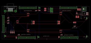
[[File:CMPE243 Eagle FoxP2.JPG|300px|thumb|right|frame|Eagle Schematic]] | [[File:CMPE243 Eagle FoxP2.JPG|300px|thumb|right|frame|Eagle Schematic]] | ||
| Line 375: | Line 457: | ||
Our team's approach to the design of this project was solely based on the integrity of its connections and communication between the nodes. Each node would handle specific parts of the car that would require an extensive amount of computing. At the center of this communication would be our design and printed PCB(printed circuit board). This board was designed in a manner that would reduce the amount of noise within the circuitry of its components, and place its nodes at an optimal location relative to the car. | Our team's approach to the design of this project was solely based on the integrity of its connections and communication between the nodes. Each node would handle specific parts of the car that would require an extensive amount of computing. At the center of this communication would be our design and printed PCB(printed circuit board). This board was designed in a manner that would reduce the amount of noise within the circuitry of its components, and place its nodes at an optimal location relative to the car. | ||
| − | |||
| − | |||
| Line 396: | Line 476: | ||
Before the Board was sent for printing, the rat nests had to be removed and the connections had to be routed in such a way that minimum amount of noise was created. this ensured a robust communication for the CAN bus and stable noise-free power supply for the external components such as the Ultrasonic Sensors. | Before the Board was sent for printing, the rat nests had to be removed and the connections had to be routed in such a way that minimum amount of noise was created. this ensured a robust communication for the CAN bus and stable noise-free power supply for the external components such as the Ultrasonic Sensors. | ||
| + | [[File:CMPE243_F17_FOXP2_overall_system_design.jpg|center|frame|thumb|Overall System Design]] | ||
| + | |||
| + | == DBC File == | ||
| + | A DBC file is used to define the CAN communication between all nodes. It is parsed using a Python script which then generates "generated_can.h" to be included by each node.<br> | ||
| + | The following is the defined DBC file for FoxP2 | ||
| + | <pre> | ||
| + | VERSION "" | ||
| + | |||
| + | NS_ : | ||
| + | BA_ | ||
| + | BA_DEF_ | ||
| + | BA_DEF_DEF_ | ||
| + | BA_DEF_DEF_REL_ | ||
| + | BA_DEF_REL_ | ||
| + | BA_DEF_SGTYPE_ | ||
| + | BA_REL_ | ||
| + | BA_SGTYPE_ | ||
| + | BO_TX_BU_ | ||
| + | BU_BO_REL_ | ||
| + | BU_EV_REL_ | ||
| + | BU_SG_REL_ | ||
| + | CAT_ | ||
| + | CAT_DEF_ | ||
| + | CM_ | ||
| + | ENVVAR_DATA_ | ||
| + | EV_DATA_ | ||
| + | FILTER | ||
| + | NS_DESC_ | ||
| + | SGTYPE_ | ||
| + | SGTYPE_VAL_ | ||
| + | SG_MUL_VAL_ | ||
| + | SIGTYPE_VALTYPE_ | ||
| + | SIG_GROUP_ | ||
| + | SIG_TYPE_REF_ | ||
| + | SIG_VALTYPE_ | ||
| + | VAL_ | ||
| + | VAL_TABLE_ | ||
| + | |||
| + | BS_: | ||
| + | |||
| + | BU_: MOTOR SENSOR GATEWAY GEOGRAPHICAL BRIDGE | ||
| + | |||
| + | |||
| + | BO_ 100 MOTOR_CMD: 1 GATEWAY | ||
| + | SG_ MOTOR_CMD_MOMENTUM : 0|4@1+ (1,0) [0|15] "" MOTOR | ||
| + | SG_ MOTOR_CMD_TURN : 4|4@1+ (1,0) [0|15] "" MOTOR | ||
| + | |||
| + | BO_ 120 RPM_VALUE_CMD: 1 MOTOR | ||
| + | SG_ RPM_VALUE_CMD_WHEEL_CLICKS : 0|8@1+ (1,0) [0|0] "" GATEWAY | ||
| + | |||
| + | BO_ 140 COMPASS_VALUE_CMD: 5 GEOGRAPHICAL | ||
| + | SG_ COMPASS_VALUE_CMD_VALID : 0|1@1+ (1,0) [0|1] "" BRIDGE,MOTOR | ||
| + | SG_ COMPASS_VALUE_CMD_VALUE : 1|32@1+ (0.000001,0) [0.000000|360.000000] "" BRIDGE,MOTOR | ||
| + | BO_ 145 GPS_VALUE_CMD: 8 GEOGRAPHICAL | ||
| + | SG_ GPS_VALUE_CMD_VALID : 0|1@1+ (1,0) [0|1] "" MOTOR,BRIDGE | ||
| + | SG_ GPS_VALUE_CMD_BEARING : 1|29@1+ (0.000001,0) [0.000000|360.000000] "" MOTOR,BRIDGE | ||
| + | SG_ GPS_VALUE_CMD_DISTANCE : 30|33@1+ (0.000001,0) [0|8000.000000] "meters" MOTOR,BRIDGE | ||
| + | BO_ 200 GEOGRAPHICAL_CMD: 8 GEOGRAPHICAL | ||
| + | SG_ GEOGRAPHICAL_CMD_direction : 0|4@1+ (1,0) [0|15] "" BRIDGE,GATEWAY | ||
| + | SG_ GEOGRAPHICAL_CMD_distance : 5|33@1+ (0.000001,0) [0|8000.000000] "meters" BRIDGE,GATEWAY | ||
| + | BO_ 300 SENSOR_PROX_STATUS: 7 SENSOR | ||
| + | SG_ SENSOR_FRONT_DIST : 0|13@1+ (1,0) [0|0] "in" BRIDGE,GATEWAY | ||
| + | SG_ SENSOR_LFRONT_DIST : 13|13@1+ (1,0) [0|0] "in" BRIDGE,GATEWAY | ||
| + | SG_ SENSOR_RFRONT_DIST : 26|13@1+ (1,0) [0|0] "in" BRIDGE,GATEWAY | ||
| + | SG_ SENSOR_REAR_DIST : 39|13@1+ (1,0) [0|0] "in" BRIDGE,GATEWAY | ||
| + | |||
| + | BO_ 400 BRIDGE_STOP: 1 BRIDGE | ||
| + | SG_ BRIDGE_STOP_CMD : 0|1@1+ (1,0) [0|1] "" GEOGRAPHICAL | ||
| + | |||
| + | BO_ 401 GEO_ALERT: 1 GEOGRAPHICAL | ||
| + | SG_ GEO_ALERT_GO_NO_CHECKPOINTS : 0|1@1+ (1,0) [0|1] "" BRIDGE | ||
| + | |||
| + | BO_ 403 BRIDGE_NUM_CHECKPOINT: 1 BRIDGE | ||
| + | SG_ BRIDGE_NUM_CHECKPOINT_CMD : 0|8@1+ (1,0) [0|255] "" GEOGRAPHICAL | ||
| + | |||
| + | BO_ 404 BRIDGE_LAT_LONG: 8 BRIDGE | ||
| + | SG_ BRIDGE_LAT : 0|32@1+ (0.000001,0) [36.0000000|38.000000] "degrees" GEOGRAPHICAL | ||
| + | SG_ BRIDGE_LONG : 32|32@1+ (0.000001,-123) [-123.0000000|-120.000000] "degrees" GEOGRAPHICAL | ||
| + | |||
| + | BO_ 405 BRIDGE_DONE: 1 BRIDGE | ||
| + | SG_ BRIDGE_DONE_CMD : 0|1@1+ (1,0) [0|1] "" GEOGRAPHICAL | ||
| + | |||
| + | BO_ 406 GEOGRAPHICAL_RESP_NUM: 1 GEOGRAPHICAL | ||
| + | SG_ GEOGRAPHICAL_RESP_NUM_CMD : 0|8@1+ (1,0) [0|255] "" BRIDGE | ||
| + | |||
| + | BO_ 407 BRIDGE_GO: 1 BRIDGE | ||
| + | SG_ BRIDGE_GO_CMD : 0|1@1+ (1,0) [0|1] "" GEOGRAPHICAL | ||
| + | |||
| + | BO_ 408 GEOGRAPHICAL_CURR_LAT_LONG: 8 GEOGRAPHICAL | ||
| + | SG_ GEOGRAPHICAL_CURR_LAT : 0|32@1+ (0.000001,0) [36.000000|38.000000] "degrees" BRIDGE | ||
| + | SG_ GEOGRAPHICAL_CURR_LONG : 32|32@1+ (0.000001,-123) [-123.000000|-120.000000] "degrees" BRIDGE | ||
| + | |||
| + | |||
| + | CM_ BU_ DRIVER "The driver controller driving the car"; | ||
| + | CM_ BU_ MOTOR "The motor controller of the car"; | ||
| + | CM_ BU_ SENSOR "The sensor controller of the car"; | ||
| + | CM_ BO_ 100 "Sync message used to synchronize the controllers"; | ||
| + | |||
| + | BA_DEF_ "BusType" STRING ; | ||
| + | BA_DEF_ BO_ "GenMsgCycleTime" INT 0 0; | ||
| + | BA_DEF_ SG_ "FieldType" STRING ; | ||
| + | |||
| + | BA_DEF_DEF_ "BusType" "CAN"; | ||
| + | BA_DEF_DEF_ "FieldType" ""; | ||
| + | BA_DEF_DEF_ "GenMsgCycleTime" 0; | ||
| + | |||
| + | BA_ "GenMsgCycleTime" BO_ 500 100; | ||
| + | BA_ "GenMsgCycleTime" BO_ 100 1000; | ||
| + | BA_ "GenMsgCycleTime" BO_ 101 100; | ||
| + | BA_ "GenMsgCycleTime" BO_ 400 100; | ||
| + | BA_ "GenMsgCycleTime" BO_ 200 100; | ||
| + | BA_ "GenMsgCycleTime" BO_ 300 100; | ||
| + | |||
| + | BA_ "FieldType" SG_ 500 DBC_TEST1_enum "DBC_TEST1_enum"; | ||
| + | BA_ "FieldType" SG_ 100 DRIVER_HEARTBEAT_cmd "DRIVER_HEARTBEAT_cmd"; | ||
| + | |||
| + | |||
| + | VAL_ 500 DBC_TEST1_enum 2 "DBC_TEST1_enum_val_two" 1 "DBC_TEST1_enum_val_one" ; | ||
| + | VAL_ 100 DRIVER_HEARTBEAT_cmd 2 "DRIVER_HEARTBEAT_cmd_REBOOT" 1 "DRIVER_HEARTBEAT_cmd_SYNC" 0 "DRIVER_HEARTBEAT_cmd_NOOP" ; | ||
| + | |||
| + | |||
| + | </pre> | ||
== Motor Controller == | == Motor Controller == | ||
Motor Controller primary tasks are as follows: | Motor Controller primary tasks are as follows: | ||
| − | |||
| − | |||
| − | |||
| − | === ESC (Electronic Speed Control) === | + | * Control the rear wheels for moving forward, backward and stop |
| + | |||
| + | * Control the front wheels to maneuver | ||
| + | |||
| + | * Display contents on the LCD | ||
| + | |||
| + | === Drivetrain === | ||
| + | |||
| + | '''''Ahsan Uddin''''' | ||
| + | |||
| + | ---- | ||
| + | |||
| + | ==== ESC (Electronic Speed Control) ==== | ||
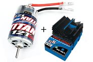
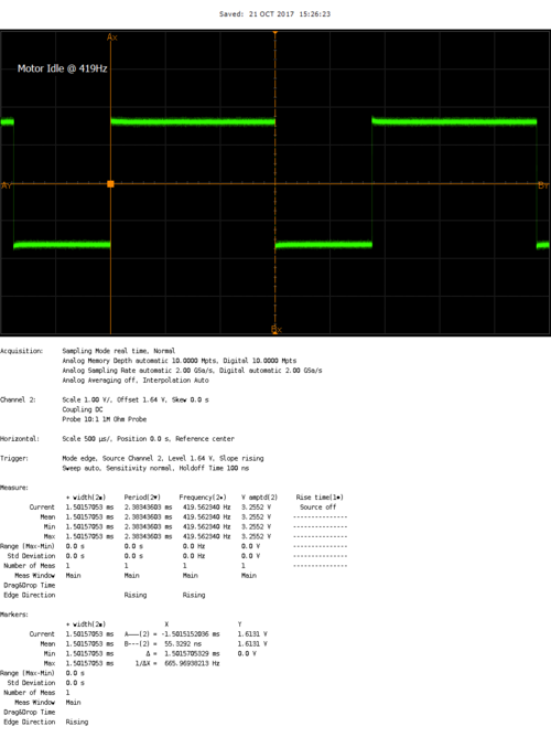
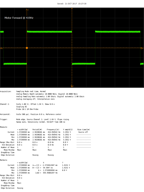
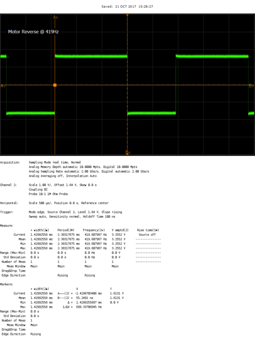
Our car came up Traxxas XL5 installed already. We knew that the onboard wireless receiver controls the ESC through PWM but we didn’t know the frequency and the duty cycle. So we hooked up the ESC with an oscilloscope and used the Wireless transmitter to go forward/backward and found out that the operating frequency of the ESC is 100Hz. | Our car came up Traxxas XL5 installed already. We knew that the onboard wireless receiver controls the ESC through PWM but we didn’t know the frequency and the duty cycle. So we hooked up the ESC with an oscilloscope and used the Wireless transmitter to go forward/backward and found out that the operating frequency of the ESC is 100Hz. | ||
| Line 425: | Line 636: | ||
[[File:Cmpe243_F17_FOXP2_Motor_IDLE_SJOne.bmp|500px|SJOne Board Idle ON PWM]] [[File:Cmpe243_F17_FOXP2_Motor_Forward_SJOne.bmp|500px|SJOne Board Forward PWM]] [[File:Cmpe243_F17_FOXP2_Motor_Reverse_SJOne.bmp|500px|SJOne Board Reverse PWM]] | [[File:Cmpe243_F17_FOXP2_Motor_IDLE_SJOne.bmp|500px|SJOne Board Idle ON PWM]] [[File:Cmpe243_F17_FOXP2_Motor_Forward_SJOne.bmp|500px|SJOne Board Forward PWM]] [[File:Cmpe243_F17_FOXP2_Motor_Reverse_SJOne.bmp|500px|SJOne Board Reverse PWM]] | ||
| − | === Servo (to turn the front wheels) === | + | ==== Servo (to turn the front wheels) ==== |
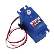
The Servo also uses PWM as an input to control the direction of the wheels. SJ One board has a limitation where all PWM signals need to be driven at the same frequency. Which means that as we are driving the ESC signals at ~420 Hz, we also had to drive the servo PWM signals at 420Hz. We had to do a parametric search of various PWM percentages to find out which ones would be best suited for turning the servos. Below are the scope shots of the PWM signals that SJOne board is using to drive the servo directions. | The Servo also uses PWM as an input to control the direction of the wheels. SJ One board has a limitation where all PWM signals need to be driven at the same frequency. Which means that as we are driving the ESC signals at ~420 Hz, we also had to drive the servo PWM signals at 420Hz. We had to do a parametric search of various PWM percentages to find out which ones would be best suited for turning the servos. Below are the scope shots of the PWM signals that SJOne board is using to drive the servo directions. | ||
| Line 431: | Line 642: | ||
[[File:Cmpe243_F17_FOXP2_SJOne_Turn_Straight.bmp|500px|SJOne Board Turn Straight PWM]] [[File:Cmpe243_F17_FOXP2_SJOne_Turn_Left.bmp|500px|SJOne Board Turn Left PWM]] [[File:Cmpe243_F17_FOXP2_SJOne_Turn_Right.bmp|500px|SJOne Board Turn Right PWM]] [[File:Cmpe243_F17_FOXP2_Traxxas_Servo.jpg|thumb|right|185px|Traxxas 2075 Servo]] | [[File:Cmpe243_F17_FOXP2_SJOne_Turn_Straight.bmp|500px|SJOne Board Turn Straight PWM]] [[File:Cmpe243_F17_FOXP2_SJOne_Turn_Left.bmp|500px|SJOne Board Turn Left PWM]] [[File:Cmpe243_F17_FOXP2_SJOne_Turn_Right.bmp|500px|SJOne Board Turn Right PWM]] [[File:Cmpe243_F17_FOXP2_Traxxas_Servo.jpg|thumb|right|185px|Traxxas 2075 Servo]] | ||
| − | === RPM Sensor (for detecting speed)=== | + | ==== RPM Sensor (for detecting speed) ==== |
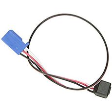
[[File:Cmpe243_F17_FOXP2_Traxxas_RPM.jpg|right|230px|Traxxas RPM sensor]] | [[File:Cmpe243_F17_FOXP2_Traxxas_RPM.jpg|right|230px|Traxxas RPM sensor]] | ||
| Line 441: | Line 652: | ||
The schematic for hooking up the RPM sensor was challenging because of the following: | The schematic for hooking up the RPM sensor was challenging because of the following: | ||
| − | + | * First we came across an issue where we were able to mount the magnet on the motor but it wasn't possible to mount the RPM sensor head inside the motor compartment. Later we found out that we needed a special compartment designed by Traxxas to hold the RPM sensor inside the motor compartment | |
| − | + | * When we were prototyping the RPM sensor on breadboard, we saw that regardless of whether we bring the magnet close to the sensor or not, the signal voltage was always high. After many researches and trail and errors we found out that the signal pin had to be connected to the VCC across a 1K resistor so that it can effectively pull it down when it detects the magnet | |
| − | + | * The Traxxas RPM sensor package came with a single magnet and a Hall effect sensor. So we put the single magnet inside the motor compartment and it was working fine when we were manually bring the hall effect sensor close by. But when we would put the motor cover on, we would see that the RPM sensor would never trigger. We fixed the issue by putting 2 magnets on top of each other to increase the magnetic field and then we were able to see the RPM sensor work seamlessly. | |
| − | === | + | ==== Hardware Interface ==== |
| − | + | * CAN bus | |
| − | |||
| − | |||
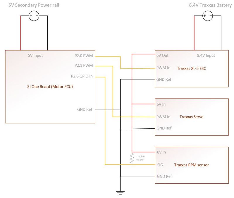
| − | + | :Motor ECU uses can1 to communicate with other ECUs. Motor primarily receives data from Master/Gateway to maneuver left/straight/right and also stop/forward/reverse the wheels. Motor also receives non-critical system data from Geographical ECU which needs to be displayed to the LCD. For the CAN configuration, we used baud rate of 100bps. | |
| − | |||
| − | + | * PWM to Motor and servo | |
| − | + | :There are 3 PWM pins available on SJ One Board. As explained earlier, all PWM frequencies were set to 420Hz. The Motor PWM PIN is driven from XXX and the servo PWM pin is driven from YYY. | |
| − | + | * RPM sensor for edge detection | |
| − | + | :The RPM input is connected to P2.6. It should be noted that there's a 1K resistor between the VCC of the RPM and the Signal Input | |
| − | + | :Motor, Servo and the RPM share the power directly from the 8.4V Traxxas battery | |
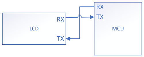
| − | + | * UART to LCD | |
| − | The | + | : LCD uses UART TX/RX port to talk to the LCD. The UART is configured at 9600 bauds/sec. |
| − | |||
| − | |||
| − | + | [[File:Cmpe243_F17_FOXP2_Motor_HW_Design.JPG|800px|middle|Motor ECU's HW design]] | |
| − | === Software Design === | + | ==== Software Design ==== |
| − | 1. | + | 1. Initialization sequence |
In the Motor ECU's init sequence we do the following in order: | In the Motor ECU's init sequence we do the following in order: | ||
| − | * CAN Init | + | * '''CAN Init''' |
| − | + | :: Motor CAN is initialized on ''can1'' with BAUD rate 100bps and TX/RX queue sizes of 100. Then the filter is setup for 100-150 MSG IDs. | |
| − | * | + | * '''PWM Init''' |
| − | + | :: 2 PWMs are set at P2.0 and P2.1 at 420Hz for Motor and Servo respectively. By default, the PWMs are set to straighten up the front wheels and put the back wheels to IDLE | |
| − | * | + | * '''LCD Init''' |
| + | |||
| + | :: UART is initialized at TXD2/RXD2 for LCD at 9600 baud rate | ||
| + | |||
| + | * '''RPM sensor Init''' | ||
| + | |||
| + | :: P2.6 PIN is initialized as input with pull down resistor and a rising edge interrupt is being installed to detect the RPM triggers | ||
2. 1 Hz Task | 2. 1 Hz Task | ||
| Line 496: | Line 708: | ||
1Hz task is responsible for: | 1Hz task is responsible for: | ||
| − | * CAN Bus reset logic | + | * '''CAN Bus reset logic''' |
| + | |||
| + | :: In this handler we simply check if the CAN bus is off or not. If it's off, we do a BUS reset | ||
| + | |||
| + | * '''Handle Manual PWM (only in debug mode)''' | ||
| − | + | :: This mode is only for debugging purpose. Just by change of a #define flag, we can shutdown all CAN related code and turn on the manual mode where we can use the on board switches to control the front and the back wheels. This has been a very effective was of debugging to find out HW related issues without taking off any of the components. | |
| − | * RPM check | + | * '''RPM check ''' |
| − | + | :: We count the number of ticks that happened in 1 sec and reset the value of the ticks, therefore we get a revolution/second value | |
| − | * Update LCD: | + | * '''Speed check ''' |
| + | |||
| + | :: We have predefined macros of what should be a high speed value and a low speed value. If we detect the current speed values are not in limit, we upshift or downshift the gears to control the speed | ||
| + | |||
| + | * '''Update LCD''' | ||
| + | |||
| + | :: We get the following data and update them to the LCDs: | ||
** RPM data | ** RPM data | ||
** Bearing data | ** Bearing data | ||
** Compass data | ** Compass data | ||
| − | * Send CAN messages | + | * '''Send CAN messages''' |
| + | |||
| + | :: We send CAN messages to Gateway with our current speed values | ||
3. 10 Hz task | 3. 10 Hz task | ||
| Line 515: | Line 739: | ||
10Hz task is responsible for: | 10Hz task is responsible for: | ||
| − | * Reverse State machine | + | * '''Reverse State machine''' |
| + | |||
| + | :: In order to reverse properly, we have to follow a specific sequences of Stop and Reverse. This handler takes care of it. Details of this state machine is described below in Bugs section | ||
4. 100 Hz task | 4. 100 Hz task | ||
| − | * Handle CAN messages | + | * '''Handle CAN messages''' |
| − | === Implementation === | + | :: This is the master handler for receiving all the CAN messages. Primarily they are motor CMDs from Gateway and compass data from Geographical for displaying on LCD. |
| − | + | ||
| + | [[File:Cmpe243_F17_FOXP2_Motor_SW_Design.JPG|1000px|middle|Motor ECU's SW design]] | ||
| + | |||
| + | ==== Implementation ==== | ||
* Overall | * Overall | ||
| Line 528: | Line 757: | ||
* Debug mode | * Debug mode | ||
| − | : In order to debug the motor side easily on the field | + | : In order to debug the motor side easily on the field we implemented a debug mode where we shut down all CAN communications and let the on board switches to control the front and the back wheels. In this mode, all the other peripherals like LCD ad RPM sensors are fully functional. |
| + | |||
| + | === LCD === | ||
| + | |||
| + | '''''Sophia Quan''''' | ||
| + | |||
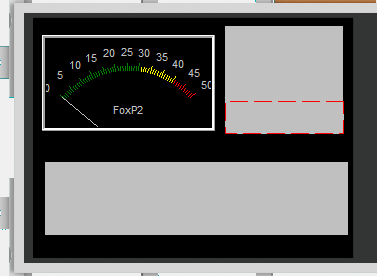
| + | The uLCD-32PTU is a 3.2" (240x320) LCD screen with a micro SD connector, GPIO's along with I2C and serial COMMS. Workshop4 IDE was used to program the GUI, and data was transmitted from the SJOne board through UART communication. The LCD displays RPM clicks, GPS heading, bearing, distance, and also the current firmware version and branch name. | ||
| + | |||
| + | [[File:Cmpe243_f17_foxp2_lcd_hw_architecture.png|500px|thumb|center|frame|LCD Hardware Architecture]] | ||
| + | |||
| + | [[File:LCD_display.PNG|750px|thumb|center|frame|LCD Display]] | ||
| + | Note: The display here shows the angularmeter which will display the rpm, the top right box will display the bearing, heading, and distance from the GPS, and the bottom box will disply the firmware git hash, and branch. | ||
| + | |||
| + | ====Software Implementation==== | ||
| + | A software abstraction layer was implemented for the LCD screen consisting of init, ack/nack, and write functions. | ||
| + | * '''INIT''' | ||
| + | Since this LCD uses UART for its communication protocol, we set the baudrate at 9600bps and define the sizes of the rx/tx buffers. | ||
| + | |||
| + | *'''ACK & NACK ''' | ||
| + | When sending data to the LCD screen, if data is successfully transmitted, the LCD screen will return a 0x06H, and if not transmitted properly, the LCD will return a 0x15H. The function to check ACK/NACK will check for these values and print to the console the proper debug message. | ||
| + | |||
| + | *''' WRITE ''' | ||
| + | The data sent to the LCD screen is in a specified format for each object as shown below: | ||
| + | |||
| + | Angularmeter: | ||
| + | BYTE0 - Event byte | ||
| + | BYTE1 - Object type | ||
| + | BYTE2 - Object index | ||
| + | BYTE3 - Data byte 1 | ||
| + | BYTE4 - Data byte 2 | ||
| + | BYTE5 - Check sum | ||
| + | |||
| + | Static String Text Box: | ||
| + | BYTE0 - Event byte | ||
| + | BYTE1 - Object type | ||
| + | BYTE2 - Object index | ||
| + | BYTE3 - Data length | ||
| + | BYTE4 - First character to be sent | ||
| + | . | ||
| + | . | ||
| + | . | ||
| + | BYTEN+4 - Last character to be sent | ||
| + | BYTEN+5 - NULL character | ||
| + | BYTEN+6 - Checksum | ||
== Sensors == | == Sensors == | ||
| + | |||
| + | '''''Jason Tran''''' and '''''Rob Nikfar''''' | ||
| + | |||
The primary responsibility of the sensor ECU is to provide object detection capabilities. | The primary responsibility of the sensor ECU is to provide object detection capabilities. | ||
| Line 539: | Line 814: | ||
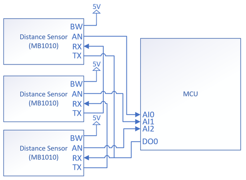
=== Hardware Interface === | === Hardware Interface === | ||
| − | [[File:cmpe243_f17_foxp2_sensor_hw_architecture.png| | + | [[File:cmpe243_f17_foxp2_sensor_hw_architecture.png|500px|thumb|center|frame|Sensor Hardware Architecture and Interface]] |
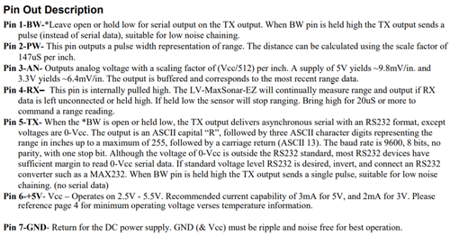
| − | Note: Despite the names, the TX and RX pins do not function as asynchronous serial transmit and receive. The TX functions as | + | Note: Despite the names, the TX and RX pins do not function as asynchronous serial transmit and receive in the implementation above. The TX functions as a digital output that drives the line high for a short duration when the sensor wants to trigger a cascaded sensor. The RX functions as an digital input that acts as a trigger for the sensor to begin measuring a distance. |
| + | [[File:Cmpe243_f17_foxp2_LV-MaSonar-EZ_Datasheet.png|500px|thumb|center|frame|MB1010 Pinout]] | ||
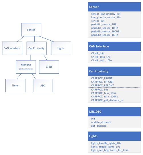
=== Software Design === | === Software Design === | ||
| − | The sensor software follows a modular design pattern. Sensors is the top level module | + | The sensor software follows a modular design pattern. Sensors is the top level module that contains periodic function definitions. The CAN Interface module consists of a periodic task that is responsible for broadcasting the most up to date sensor readings over CAN. The Car Proximity module also consists of several periodic tasks that are responsible for managing the frontal sensor readings. |
| − | [[File:CmpE243_F17_FoxP2_Sensor_SW_Architecture.png| | + | [[File:CmpE243_F17_FoxP2_Sensor_SW_Architecture.png|500px|thumb|center|frame|Sensor Software Architecture]] |
| + | === Implementation === | ||
| + | At 100Hz, the ECU reads the analog voltage of all 3 sensors, performs scaling on the raw ADC values to decode the voltage into inches, then stores the value in 3 circular buffers respectively. A circular buffer represents a history of inches reported by a sensor; the most recent firmware version stores the 3 most recent sensor readings into a circular buffer which represents a 30ms time frame. | ||
| − | + | At 10Hz, the ECU broadcasts the distance of all 3 sensors over CAN. | |
| − | + | ||
| + | Filtering is also applied against the circular buffers. Of the data in a given circular buffer, the ECU reports the minimum distance. | ||
| + | There are 3 onboard LEDs that represent the state of the 3 frontal sensors. The LEDs are driven by GPIO. If, for example, the front sensor detects an object, then the ECU will assert the center onboard LED. | ||
== Geographical Controller== | == Geographical Controller== | ||
| + | |||
| + | '''''Yuyu Chen''''' | ||
| + | |||
The main purpose of the geographical controller is to guide the car towards its destination. This is done by processing data from the GPS and Compass module in order to get the '''Heading''', '''Bearing''', and '''Distance'''. <br> | The main purpose of the geographical controller is to guide the car towards its destination. This is done by processing data from the GPS and Compass module in order to get the '''Heading''', '''Bearing''', and '''Distance'''. <br> | ||
| − | The compass will allow the user to calculate the '''Heading''', which tells us which direction the car is pointing relative to magnetic north | + | The compass will allow the user to calculate the '''Heading''', which tells us which direction the car is pointing relative to magnetic north or simply, '''"Which way the car is pointing"'''?<br> |
The GPS will allow the user to get the current coordinate of the car, which will be useful when calculating the '''Bearing''' and '''Distance'''.<br> | The GPS will allow the user to get the current coordinate of the car, which will be useful when calculating the '''Bearing''' and '''Distance'''.<br> | ||
The '''Bearing''' tells us the direction from the current location to a checkpoint coordinate, and is given as the angle between the location and the current location of the car.<br> | The '''Bearing''' tells us the direction from the current location to a checkpoint coordinate, and is given as the angle between the location and the current location of the car.<br> | ||
| Line 568: | Line 851: | ||
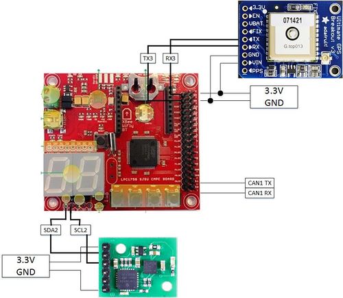
=== Hardware Design === | === Hardware Design === | ||
| − | |||
[[File:CMPE243_F17_FOXP2_geo_block_diagram.jpg|500px]] | [[File:CMPE243_F17_FOXP2_geo_block_diagram.jpg|500px]] | ||
| Line 580: | Line 862: | ||
<br> | <br> | ||
<br> | <br> | ||
| − | The MTK3339 Ultimate GPS module from Adafruit was chosen because it provided good results when it was used previously for a different project. The main purpose of the GPS module is to provide an accurate location of the car while the car navigates towards its destination. This is done by parsing NMEA sentences, which are transmitted by 22 satellites to pinpoint the current location of the module. There are various different types of NMEA sentences, such as $GPRMC and $GPGGA. The NMEA sentence that was used was $GPRMC, which provides only the recommended minimum. $GPRMC was also chosen because it is the only NMEA sentence the GPS module is able to provide data at 10Hz for real-time application. The module is interfaced via '''UART''' with a baud-rate set to 57600bps. The module also comes with a fix LED, which indicates if a GPS fix by blinking every 15 seconds, if not, it blinks every 1Hz. The module is powered by 3.3V from the SJOne board. | + | The MTK3339 Ultimate GPS module from Adafruit was chosen because it provided good results when it was used previously for a different project. The main purpose of the GPS module is to provide an accurate location of the car while the car navigates towards its destination. This is done by parsing NMEA sentences, which are transmitted by up to 22 satellites to pinpoint the current location of the module. There are various different types of NMEA sentences, such as $GPRMC and $GPGGA. The NMEA sentence that was used was $GPRMC, which provides only the recommended minimum. $GPRMC was also chosen because it is the only NMEA sentence the GPS module is able to provide data at 10Hz for real-time application. The module is interfaced via '''UART''' with a baud-rate set to 57600bps. The module also comes with a fix LED, which indicates if a GPS fix by blinking every 15 seconds, if not, it blinks every 1Hz. The module is powered by 3.3V from the SJOne board. |
<br> | <br> | ||
[[File:CMPE243_F17_FOXP2_gps_module.jpg|150px]] | [[File:CMPE243_F17_FOXP2_gps_module.jpg|150px]] | ||
| Line 660: | Line 942: | ||
bool gps_init(gps_data_ready_cb cb); bool cmps11_init(void); bool geo_sensor_init(void); | bool gps_init(gps_data_ready_cb cb); bool cmps11_init(void); bool geo_sensor_init(void); | ||
bool get_lat_long(float *gps_data); float cmps11_get_heading(void); void geo_sensor_run(void); | bool get_lat_long(float *gps_data); float cmps11_get_heading(void); void geo_sensor_run(void); | ||
| − | bool cmps11_calibrate(bool start_calibration, bool end_calibration); | + | bool cmps11_calibrate(bool start_calibration, bool end_calibration); |
The GPS library and Compass library are used by Geo_Sensor in order to calculate the Heading, Bearing, and Distance when geo_sensor_run() is called. Extern variables are used to share data between the CAN layer and Geo_Sensor. <br> | The GPS library and Compass library are used by Geo_Sensor in order to calculate the Heading, Bearing, and Distance when geo_sensor_run() is called. Extern variables are used to share data between the CAN layer and Geo_Sensor. <br> | ||
| Line 705: | Line 987: | ||
'''Compass'''<br> | '''Compass'''<br> | ||
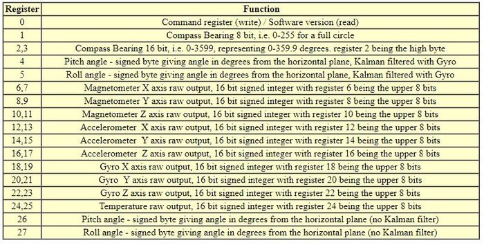
The compass will provide the Heading, which tells us the direction where the car is facing. It is interfaced via I2C. The Heading value is in units of degree, from 0 degree to 360 degree. Only two registers are read (Hi and Lo) for heading value. <br> | The compass will provide the Heading, which tells us the direction where the car is facing. It is interfaced via I2C. The Heading value is in units of degree, from 0 degree to 360 degree. Only two registers are read (Hi and Lo) for heading value. <br> | ||
| + | Register 2 & 3 are read to get the heading value | ||
| + | uint16_t heading = 0; | ||
| + | uint8_t heading_byte[2] = {0}; | ||
| + | s_compass->readRegisters(CMPS11_ADDR, heading_16_bit_hi, &heading_byte[0], 2); | ||
| + | heading = heading_byte[0] << 8 | heading_byte[1]; | ||
| + | <br> | ||
| + | There is a calibration sequence in order to initiate calibration mode. | ||
| + | 3 separate I2C transactions are needed by first writing 0xF0 to Register 0, second write of 0xF5 to Register 0, and 0xF6 to Register 0.<br> | ||
| + | After entering calibration mode, the module is needs to be rotated slowly on all axis to calibrate the magnetometer. After all the LED on the module stops blinking, place the module on all 6 sides to calibrate the accelerometer.<br> | ||
| + | After calibrating the compass module, 0xF8 is written to Register 0 to end calibration mode. | ||
| + | [[File:CMPE243_F17_FOXP2_cmps11_regmap.jpg|thumb|center|700px|cmps11 register map]] | ||
'''Geo-Sensor'''<br> | '''Geo-Sensor'''<br> | ||
| Line 716: | Line 1,009: | ||
d = Radius of Earth * c | d = Radius of Earth * c | ||
<br> | <br> | ||
| − | The heading, bearing, and distance values are shared with the CAN layer for further manipulation. A simple moving average with a window of 10 was implemented to filter out bad GPS parsing (corrupt data) which occur after some time. Any distance value above the moving average will mark the GPS data as invalid. <br> | + | The heading, bearing, and distance values are shared with the CAN layer for further manipulation. A simple moving average with a window of 10 was implemented to filter out bad GPS parsing (corrupt data) which occur after some time. Any distance value above the moving average will mark the GPS data as invalid and is dropped. <br> |
To navigate the car in the direction of the destination, the difference of the heading and bearing will have to be approximately zero. After many test runs, the team realize that the car moves to the right when the steering is straight. To account for this, the threshold for which to turn right is decreased so that it will turn right less. | To navigate the car in the direction of the destination, the difference of the heading and bearing will have to be approximately zero. After many test runs, the team realize that the car moves to the right when the steering is straight. To account for this, the threshold for which to turn right is decreased so that it will turn right less. | ||
Difference = Heading - Bearing | Difference = Heading - Bearing | ||
| − | The distance to mark a checkpoint as reached is | + | [[File:CMPE243_F17_FOXP2_heading_bearing.jpg|500px]] |
| + | <br> | ||
| + | The difference between heading and bearing will tell us the offset between the direction of the current checkpoint and the current location of the car. It should steer the difference amount in order to go in direction of the checkpoint. | ||
| + | |||
| + | The distance to mark a checkpoint as reached is 5 meters radius from the actual destination, which accounts for some GPS inaccuracy. Therefore it will reach its destination within a 10 meter diameter. 5 meters was chosen after many test runs and seems to best fit because it does not over/under-shoot the checkpoint.<br> | ||
[[File:CMPE243_F17_FOXP2_geo_bridge_sm.jpg|300px|left|thumb|frame|geo bridge state machine]] | [[File:CMPE243_F17_FOXP2_geo_bridge_sm.jpg|300px|left|thumb|frame|geo bridge state machine]] | ||
| Line 730: | Line 1,027: | ||
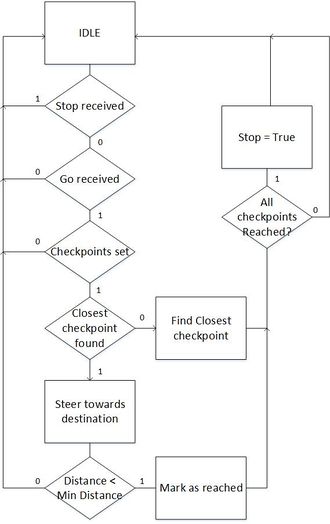
To command the car to navigate towards the destination, a '''GO''' signal needs to be sent from the Android App. To stop the car, a '''STOP''' signal is also sent from the Android App. After receiving checkpoints from the Bridge/App and Go is received, the Geographical controller will calculate which checkpoint is the closest based on distance between the checkpoints and the car's current location. After reaching that checkpoint, mark the checkpoint as "reached" to skip that checkpoint and find the next closest checkpoint until all checkpoint has been reached. The checkpoint algorithm for the Geographical controller is the right one above. | To command the car to navigate towards the destination, a '''GO''' signal needs to be sent from the Android App. To stop the car, a '''STOP''' signal is also sent from the Android App. After receiving checkpoints from the Bridge/App and Go is received, the Geographical controller will calculate which checkpoint is the closest based on distance between the checkpoints and the car's current location. After reaching that checkpoint, mark the checkpoint as "reached" to skip that checkpoint and find the next closest checkpoint until all checkpoint has been reached. The checkpoint algorithm for the Geographical controller is the right one above. | ||
| + | == Bridge Controller== | ||
| − | + | '''''Marvin Flores & Yuyu Chen''''' | |
| − | The Bridge controller's main purpose is act as a bridge between the Android Application and the car. The Android app is able to send and receive data wirelessly via Bluetooth. Any data, such as sensor data and current car location, can be sent to the bridge from other controllers via CAN. The Bridge controller will send the data wirelessly to the Android app to be displayed.<br> | + | |
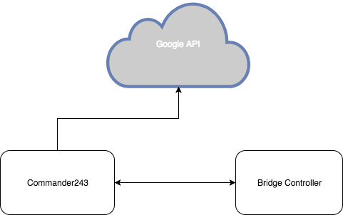
| + | The Bridge controller's main purpose is to act as a bridge between the Android Application and the car. The Android app is able to send and receive data wirelessly via Bluetooth. Any data, such as sensor data and current car location, can be sent to the bridge from other controllers via CAN. The Bridge controller will send the data wirelessly to the Android app to be displayed.<br> | ||
The main purpose of the Bridge Controller is to send checkpoints to the Geographical controller. This will be explained in the Implementation section of the Bridge Controller. | The main purpose of the Bridge Controller is to send checkpoints to the Geographical controller. This will be explained in the Implementation section of the Bridge Controller. | ||
| − | |||
| − | |||
| − | |||
=== Hardware Interface === | === Hardware Interface === | ||
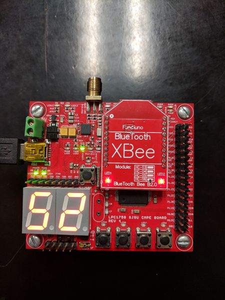
| − | A Bluetooth module is on the Bridge controller for | + | [[File:Cmpe243_F17_FOXP2_Bridge_Bluetooth_module_on_board.jpg|450px|thumb|center|frame|Bluetooth module on the SJSUOne board]] |
| + | Since SJOne Board has an XBee interface, The Bluetooth XBee module was the easiest to interface with. A Bluetooth module is installed on the Bridge controller for communication between the SJOne board and the Android App. The Bluetooth module is interfaced via SJOne board's UART. | ||
=== Software Design === | === Software Design === | ||
In order to receive or send data, an additional command is added to the TerminalTask to handle Bluetooth Commands.<br> | In order to receive or send data, an additional command is added to the TerminalTask to handle Bluetooth Commands.<br> | ||
| + | |||
| + | //Pseudocode command handler, bluetoothMessage is an extern variable that is defined in the periodic_task bridge class | ||
| + | if command == "signal go" -> bluetoothMessage.setGoSignal() | ||
| + | else if command == "signal stop" -> bluetoothMessage.setStopSignal() | ||
| + | else if command == "data_start" -> payloadSize = arg1 | ||
| + | else if command == "checkpoint" -> checkpoints[index].latitude = arg1, checkpoints[index].longitude = arg2 | ||
| + | else if command == "data_end" -> bluetoothMessage.setPayload(checkpoints, payloadSize) | ||
| + | |||
| + | Periodic Task Bridge class functions <br> | ||
| + | {| class="wikitable" | ||
| + | |- | ||
| + | ! scope="col"| Task | ||
| + | ! scope="col"| Description | ||
| + | |- | ||
| + | ! scope="row"| bridge_init() | ||
| + | | CAN_init() | ||
| + | |- | ||
| + | ! scope="row"| bridge_1Hz() | ||
| + | | CAN_reset_bus() <br> | ||
| + | sendHeartbeat() - to Android App <br> | ||
| + | sendGPSCoordinates() - to Android App <br> | ||
| + | sendSensorValues() - to Android App <br> | ||
| + | |- | ||
| + | ! scope="row"| bridge_10Hz() | ||
| + | | | ||
| + | <br> | ||
| + | bridge_geo_handshake() -> to Geo <br> | ||
| + | sendCheckPoints() -> to Geo <br> | ||
| + | sendStart() -> to Geo <br> | ||
| + | sendStop() -> to Geo <br> | ||
| + | <br> | ||
| + | |- | ||
| + | ! scope="row"| bridge_100Hz() | ||
| + | | can_rx() | ||
| + | |- | ||
| + | ! scope="row"| bridge_1kHz() | ||
| + | | N/A | ||
| + | |} | ||
=== Implementation === | === Implementation === | ||
| − | [[File:bridge_geo_state_machine.jpg| | + | [[File:bridge_geo_state_machine.jpg|330px|center|thumb|frame|bridge_geo_handshake]] |
<br> | <br> | ||
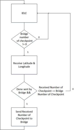
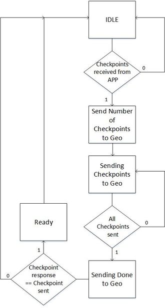
A Bridge-Geo handshake was designed in order to send checkpoints to the Geographical controller. Checkpoints are received from the Android App after the '''"Checkpoints"''' button on the app is pressed. This will initiate sending the number of checkpoints to the Geographical controller. After sending the number of checkpoints, the Bridge will start sending checkpoints to the Geographical controller. After all checkpoints are sent, the Bridge will send a '''Done''' signal to the Geographical to notify it that it has finish sending checkpoints. After receiving a response with the correct number of checkpoints sent, the Bridge will be notified that the handshake is complete and '''"Go"''' can be pressed on the Android App. The state machine for the Bridge-Geo handshake is above. | A Bridge-Geo handshake was designed in order to send checkpoints to the Geographical controller. Checkpoints are received from the Android App after the '''"Checkpoints"''' button on the app is pressed. This will initiate sending the number of checkpoints to the Geographical controller. After sending the number of checkpoints, the Bridge will start sending checkpoints to the Geographical controller. After all checkpoints are sent, the Bridge will send a '''Done''' signal to the Geographical to notify it that it has finish sending checkpoints. After receiving a response with the correct number of checkpoints sent, the Bridge will be notified that the handshake is complete and '''"Go"''' can be pressed on the Android App. The state machine for the Bridge-Geo handshake is above. | ||
== Android Application == | == Android Application == | ||
| + | |||
| + | '''''Marvin Flores''''' | ||
=== Main Tasks === | === Main Tasks === | ||
| Line 771: | Line 1,108: | ||
=== Implementation === | === Implementation === | ||
| + | [[File:Cmpe243_F17_FOXP2_Android_screenshot02.png|thumb|450px|center|frame|Commander243 Android Application - Start navigation]] | ||
| + | |||
| + | [[File:Cmpe243_F17_FOXP2_Android_screenshot03.png|thumb|450px|center|frame|Commander243 Android Application - Destination reached]] | ||
| + | |||
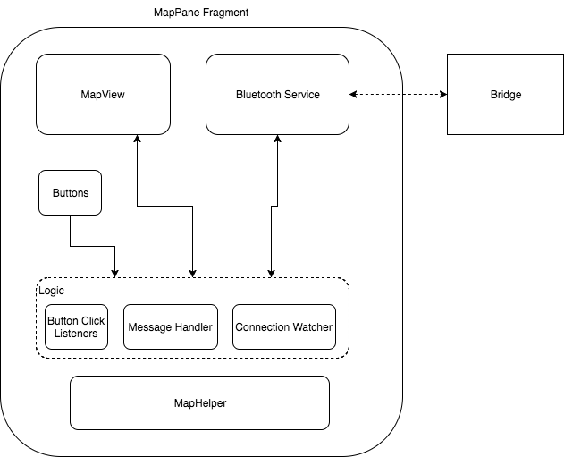
[[File:Cmpe243_F17_FOXP2_android_architecture.png|center|frame|Android Architecture Diagram]] | [[File:Cmpe243_F17_FOXP2_android_architecture.png|center|frame|Android Architecture Diagram]] | ||
| Line 791: | Line 1,132: | ||
This helper class is responsible of requesting a GET REST call to Google Maps API. It's also responsible of parsing the Json response and extract the checkpoints. | This helper class is responsible of requesting a GET REST call to Google Maps API. It's also responsible of parsing the Json response and extract the checkpoints. | ||
| − | + | === Use Cases === | |
| + | |||
| + | ==== Auto Connect ==== | ||
| + | |||
| + | [[File:Cmpe243_F17_FOXP2_Android_flow_diagram_bt_connect.png|center|frame|Flow Diagram Bluetooth Auto-connect]] | ||
| + | |||
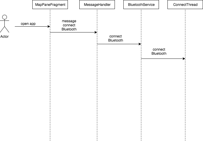
| + | The auto-connect feature happens right after the user opens up the application. During startup, the MapFragment sends a connect message to the MessageHandler. The MessageHandler of the BluetoothService receives it and calls the appropriate method on the BluetoothService. The method then initializes the ConnectThread class that handles the Bluetooth socket connection. | ||
| + | Since the default Android's BluetoothListener only triggers once when gets disconnected, the author decided to create a custom Watcher to monitor the Bluetooth connection. This was done by checking the heartbeat coming from the Bridge Controller once connection is established. If the heartbeat message is lost for a given amount of time, the Watcher automatically reconnects to the bridge by resending the connect message from the MapPaneFragment. | ||
| + | |||
| + | ==== Send Checkpoints ==== | ||
| + | |||
| + | [[File:Cmp243_F17_FOXP2_Android_flow_diagram_send_checkpoints.png|center|frame|Flow Diagram Send Checkpoints]] | ||
| + | |||
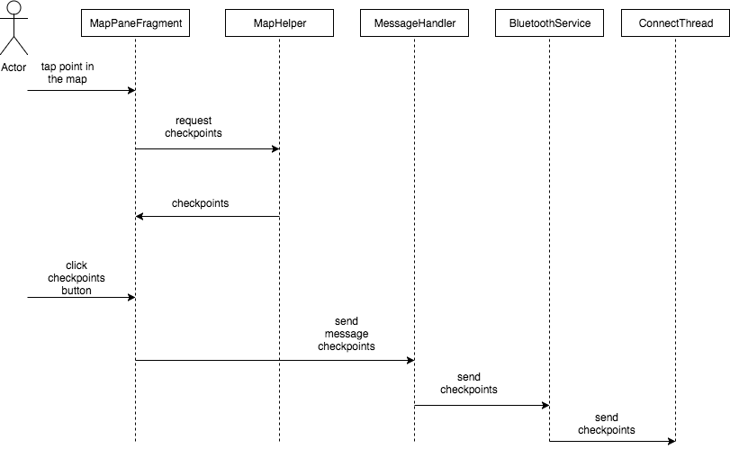
| + | * User tap a location in the MapView. | ||
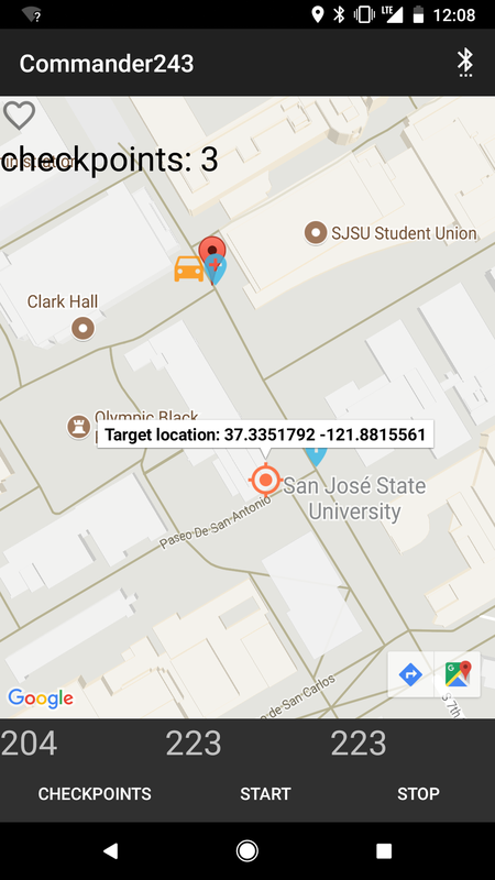
| + | * MapView has a click listener that initiates (with the help of MapHelper) a GET request to Google Maps API based on the phone location and the target location. | ||
| + | * The json response is then parsed and the checkpoints gets extracted, the target location and the checkpoints are now shown to the MapView. | ||
| + | * The user then clicks the CHECKPOINTS button | ||
| + | * Button Click Listener invokes a sendMessage that contains the checkpoints | ||
| + | * MessageHandler from the BluetoothService receives the message and forwards it to the ConnectThread. | ||
| + | * ConnectThread invokes ConnectedThread write function to send the message as bytestream to the Bridge Controller via Bluetooth. ConnectedThread gets initialized right after the connection is established. | ||
| + | * Once checkpoints are sent, the START/STOP command can be sent using similar process (without the MapHelper part). | ||
| + | |||
| + | == Gateway/Master Controller == | ||
| + | |||
| + | '''''Rabeel Elahi''''' | ||
| + | |||
| + | The Gateway/Master controller is one controller however, as the name suggests, it is responsible for two main functions: | ||
| + | |||
| + | * Gateway: Receiving, processing, and forwarding CAN messages to the respective nodes | ||
| + | * Master: Running object detection | ||
| + | |||
| + | |||
| + | [[File:Cmpe243_F17_FOXP2_Gateway_Master_Architecture.png|thumb|center|500px|Gateway/Master Architecture]] | ||
| + | |||
| + | === Gateway === | ||
| + | |||
| + | ==== FullCAN Hardware Layer ==== | ||
| + | |||
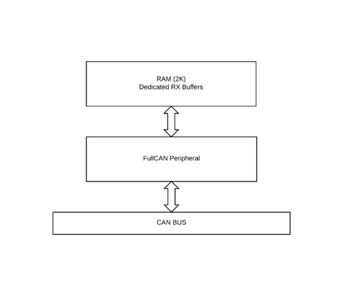
| + | [[File:Cmpe243_F17_FOXP2_FullCAN_Diagram.png|500px|thumb|right|FullCAN]] | ||
| + | |||
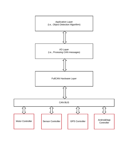
| + | The CAN controller can be driven by two principles known as BasicCAN or FullCAN. The advantage and disadvantages of both are listed below. The Gateway/Master utilizes FullCAN because the number of received messages were a finite number (< 10). However, the API has been designed to be scalable so more messages could be added if need be. Additionally, to minimize CPU usage by not polling for received messages in BasicCAN, FullCAN stores received messages into dedicated RX buffers without any CPU cycles. | ||
| + | |||
| + | --'''''BasicCAN'''''-- | ||
| + | |||
| + | '''Pros''' | ||
| + | |||
| + | 1. Not limited to a finite number of receive messages | ||
| + | |||
| + | '''Cons''' | ||
| + | |||
| + | 1. One RX Buffer (FIFO) | ||
| + | |||
| + | 2. FIFO management -- needs to be checked periodically | ||
| + | |||
| + | 3. Received CAN identifier needs to compared with list of identifiers -- Time complexity: O(N) | ||
| + | |||
| + | 4. Burden of message filtering | ||
| + | |||
| + | 5. Messy Scalability | ||
| + | |||
| + | --'''''FullCAN'''''-- | ||
| + | |||
| + | '''Pros''' | ||
| + | |||
| + | 1. Set of dedicated RX buffers | ||
| + | |||
| + | 2. Configured messages go straight to predefined section of CAN RAM – no CPU cycles required for transfer | ||
| + | |||
| + | 3. Hardware filtering | ||
| + | |||
| + | 4. Ability to check if a new message arrived | ||
| + | |||
| + | 5. Clean Scalability | ||
| + | |||
| + | '''Cons''' | ||
| + | |||
| + | 1. Limited to a finite number of received messages due to max 2k CAN RAM | ||
| + | |||
| + | |||
| + | ==== Software Design ==== | ||
| + | |||
| + | [[File:Cmpe243_F17_FOXP2_gateway_fullCAN.png|500px|thumb|right|FullCAN]] | ||
| + | |||
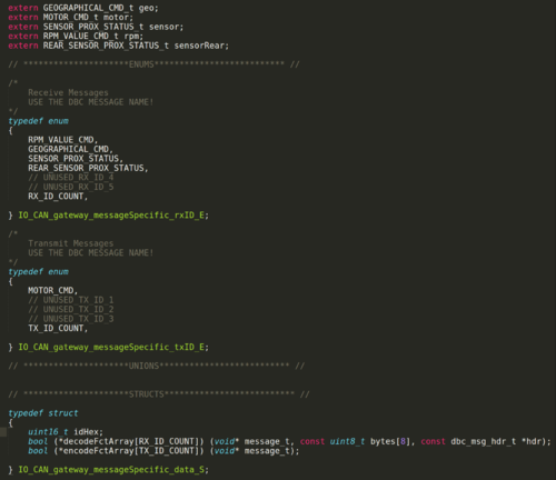
| + | The goal of the IO layer is to make it straight and simple to add a new message to the gateway/master controller. After a new message has been added, the API automatically initializes FullCAN, adds the new message to FullCAN's hardware message filter, and takes care of either encoding or decoding the message periodically. High level layers can access the encoded or decoded data by simply calling the struct handle for the respective message. | ||
| + | |||
| + | '''The following steps briefly describes how the API accomplishes this:''' | ||
| + | |||
| + | 1. Add the message to respective enum, TX or RX and extern the generated can struct handles (e.g., extern RPM_VALUE_CMD_t rpm) | ||
| + | |||
| + | 2. In the struct array definition, with the enum index you just defined above, define the CAN message hex id and add the generated decode function to the respective function pointer array for the message | ||
| + | |||
| + | 3. Add a struct getter function for the message in IO_CAN_gateway.c | ||
| + | |||
| + | 4. Add IO_gateway_init and IO_gateway_run_100ms to your periodics | ||
| + | |||
| + | 5. Call the struct handle to write or read data | ||
| + | |||
| + | |||
| + | |||
| + | |||
| + | |||
| + | |||
| + | |||
| + | |||
| + | |||
| + | |||
| + | |||
| + | |||
| + | |||
| + | |||
| + | |||
| + | |||
| + | |||
| + | |||
| + | |||
| + | |||
| + | |||
| + | |||
| + | === Master === | ||
| + | |||
| + | ==== Object Detection ==== | ||
| + | |||
| + | |||
| + | |||
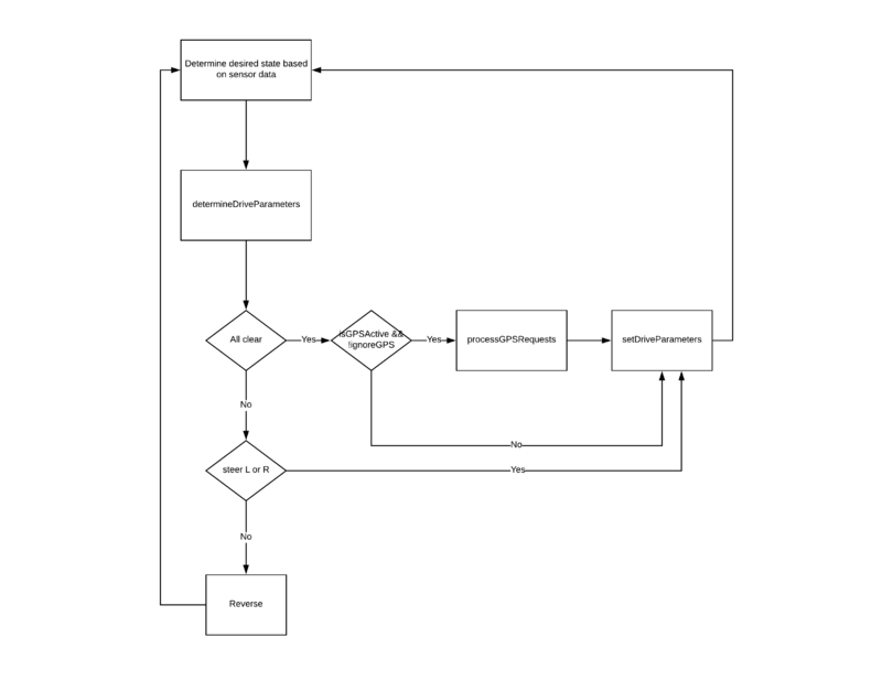
| + | The object detection algorithm is a simple state machine. The input is ultrasonic data from the sensor controller and the outputs are motor commands to the motor controller. | ||
| + | |||
| + | ==== Software Design ==== | ||
| + | |||
| + | [[File:Cmpe243_F17_FOXP2_MasterFlow.png|800px|thumb|center|Object Detection]] | ||
| + | |||
| + | ==== Implementation ==== | ||
| + | |||
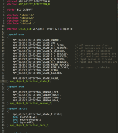
| + | [[File:Cmpe243_F17_FOXP2_ObjectDetection.png|400px|thumb|right|Object Detection States]] | ||
| + | |||
| + | 1. Determine desired state based on ultrasonic data | ||
| + | |||
| + | else if ((app_object_detection_getSensorData(APP_OBJECT_DETECTION_SENSOR_LEFT) >= app_object_detection_config.sensorThreshInInches) && | ||
| + | (app_object_detection_getSensorData(APP_OBJECT_DETECTION_SENSOR_RIGHT) >= app_object_detection_config.sensorThreshInInches) && | ||
| + | (app_object_detection_getSensorData(APP_OBJECT_DETECTION_SENSOR_FRONT) >= app_object_detection_config.sensorThreshInInches)) | ||
| + | { | ||
| + | state = APP_OBJECT_DETECTION_STATE_ALL_CLEAR; | ||
| + | } | ||
| + | |||
| + | 2. if (currentState != desiredState) | ||
| + | |||
| + | * exitAction(currentState); | ||
| + | * entryAction(desiredState); | ||
| + | * currentState = desiredState; | ||
| + | |||
| + | 4. Select motor parameters based on current state | ||
| + | |||
| + | *runAction(currentState); | ||
| + | |||
| + | case APP_OBJECT_DETECTION_STATE_ALL_BLOCKED: | ||
| + | app_object_detection_setMotorParameters(MOMENTUM_STOP, TURN_STRAIGHT); | ||
| + | app_object_detection_data.reverseRequest = true; | ||
| + | break; | ||
| + | |||
| + | |||
| + | |||
| + | |||
| + | |||
| + | |||
| + | -- | ||
== SCons - Build Automation == | == SCons - Build Automation == | ||
| + | |||
| + | '''''Jason Tran''''' | ||
SCons is a build automation tool similar to Make and is based on the Python programming language. The 2 documents below describe the basic usage of SCons to build firmware and unit tests. | SCons is a build automation tool similar to Make and is based on the Python programming language. The 2 documents below describe the basic usage of SCons to build firmware and unit tests. | ||
| Line 800: | Line 1,306: | ||
[[File:cmpe243_f17_foxp2_SCons_Building_Unit_Tests.docx|750px|thumb|center|frame|Building Unit Tests]] | [[File:cmpe243_f17_foxp2_SCons_Building_Unit_Tests.docx|750px|thumb|center|frame|Building Unit Tests]] | ||
| + | |||
| + | |||
| + | Reference source code: | ||
| + | |||
| + | [https://bitbucket.org/cmpe243f17/foxp2/src/70cfcf22095e00ef079fe45c088908d1b0a0ec02/SConscript?at=master&fileviewer=file-view-default Scons BitBucket link] | ||
| Line 824: | Line 1,335: | ||
== Validation and Testing Plan == | == Validation and Testing Plan == | ||
| + | |||
| + | '''''Michael Jaradah and Taylor Kearns''''' | ||
| Line 903: | Line 1,416: | ||
== Testing & Technical Challenges == | == Testing & Technical Challenges == | ||
| − | |||
| − | |||
| − | + | * '''Integration testing on Pull requests to Master branch''' | |
| − | === | + | : We had a very strict rule in our project where any pull request to master branch had to be checked independently by the Testing team before its approved for merging. The challenging part was that, even though thanks to SCons all the ECU codes were residing in one workspace, we had compile and burn the FW image 5 times separately on each boards and do testing against each and every one of the testing criteria. We limited this effort by making anther rule that there could only be a single PR in a day so that the testing team can efficiently check each PRs against their testing criteria and confirm that the PR is safe. This routine was extremely helpful in the integration and helped us immensely by making sure that there was not a single instance where our code build or functionality was ever broken! |
| − | + | ||
| + | * '''Ultrasonic sensors being extremely sensitive to temperature''' | ||
| + | |||
| + | : Throughout our integration testing we were surprised to see that the Ultrasonic sensors were extremely sensitive to external temperatures. As we approached our demo day, which also means the cold weather was slowly invading us, we saw increasingly erroneous behavior from our ultrasonic sensors. Luckily we were able to get around it by putting mounts around the sensors which made the sensors somewhat less sensitive to cold. Another option for us was to use the LIDAR but were skeptical to do that as we knew that Lidar was extremely power hungry and it would be sensitive to sunlight, especially when our demo would be in an early morning where the sunshine would possibly be shining directly to the LIDARs. | ||
| + | |||
| + | == Bugs/Issues == | ||
| + | |||
| + | === ESC Initialization sequence === | ||
| + | |||
| + | The Electronic speed control (ESC) unit is driven by PWM input signals and are pretty sensitive to the timings. We faced an issue where the ESC would keep blinking green LED which means that it can't detect the input signals even though the SJ One board is connected to the ESC driving the PWM signals. After a lot of scoping we found out that when the ESC is turned ON, its important that the SJ One baord has to send the same IDLE signature PWM to the ESC in order for it to detect the driver. Until this happens, the ESC will be in reset mode. Therefore, in our Init sequence for the SJ One board we made sure that upon start up, we send in the IDLE PWM sequence and then only we send other signals like forward, reverse, etc. | ||
| + | |||
| + | === Reversing the ESC === | ||
| + | |||
| + | During the initial stage of the system bring up we saw that even though we were putting the exact PWM frequency to the ESC to reverse, but for some reason it would never reverse. Through a lot of trial and error we found out that due to security reasons for protecting the motor from burning out when switching momentum at high speed, its intentionally designed to not reverse when the reverse signal comes while the motor is going forward. And hence we had to put a workaround where we created a state machine which will cycle through the following states when it will receive reverse command fro gateway: | ||
| + | |||
| + | * Stop | ||
| + | * Reverse | ||
| + | * Stop | ||
| + | * Reverse | ||
| + | |||
| + | At the 4th cycle of the state machine it would start reversing. But the challenging part was that we had to cycle through these states with a gap of 100ms or so and it was not possible to simply put a delay in the tasks as the task would take 500ms and would be over run. Instead we implemented a circular ping mechanism where we would change the state machine from the 10Hz callback and cycle through the state machines. It should be noted that during this 500ms, motor ECU ignores all other commands from Gateway. But as the car is sitting IDLE in this 500ms so motor doesn't expect Gateway to send any system critical CMD. | ||
| + | |||
| + | ===FullCAN Initialization=== | ||
| + | |||
| + | When generating FullCAN IDs, the SJ1 would crash when adding new messages. It wasn't initially clear as to why this was happening, but after taking some educated guesses it turned out that CAN IDs needed to be added to the FullCAN hardware filter starting from least to greatest. | ||
| + | |||
| + | ===Corrupt GPS NMEA sentences=== | ||
| + | After some time corrupt NMEA sentences would appear and give us erroneous values for latitude and longitude. Bad data will give us the wrong distance and bearing values. Since NMEA sentences have fixed formats and are delimited by commas, we know which data to pull out of the NMEA sentence. Rigorous unit testing has been done on the GPS module. But when its corrupt, the data becomes useless and should not be accounted for. Since the GPS is receiving data every 10Hz, the issue could be the UART baud rate. The issue is still unknown, but a filter has been set up to ignore any corrupt data. A Simple Moving Average with a window size of 10 was implemented to filter out any spike (corrupt data) on the calculated distance. Since we know that as the car gets closer to its destination, the distance decreases. If any data is above the moving average times some constant, the data is ignored. | ||
== Conclusion == | == Conclusion == | ||
| − | + | ||
| + | This project gave us the opportunity to work on a system where multiple modules talk to each other and they all have critical duties which is required to get the whole system working. Our group had a mixture for experienced engineers who come from different industry backgrounds and we learnt so much from each other while being in an academic background. The thrilling experience of working on a self driving car and designing it from scratch was a huge accomplishment in this semester for all of us. At the beginning of the semester we were unsure of the challenges that we will be facing but now when we look back, we can see the tremendous amount of learning curve we had and of course all the lessons that we learnt from solving the issues and facing the challenges. Outside of the technical learning, we also learnt hands on about people and project management and was able to successfully implement Agile methodology in our development cycles. All these experiences are going to hep us tremendously in our future endeavors. | ||
=== Project Video === | === Project Video === | ||
| − | + | [https://youtu.be/R2bnKiLIw10 FoxP2 Project Video] | |
| + | <br> | ||
| + | [https://www.youtube.com/watch?v=ebUbtB99FTA&t=1s FoxP2 Demo Day Video] | ||
=== Project Source Code === | === Project Source Code === | ||
| − | * | + | |
| + | [https://bitbucket.org/cmpe243f17/foxp2 BitBucket Source Code Repo] | ||
| + | |||
| + | [https://gitlab.com/nivram07/Commander243 Gitlab Android Application Repo] | ||
| + | |||
| + | == Lessons Learned == | ||
| + | |||
| + | === Design for Debug (DFD) === | ||
| + | |||
| + | In our project we moved onto PCB very early in the project life cycle. While in one hand it gives the whole project a very cool look and reduces fly wire uses but at the same time it severely hinders HW debugging capability. For example, initially when the RPM sensor was tested on component level, it was very easy for us to characterize the behaviors by simple connecting the RPM sensor on a breadboard and using a scope with fly wires to observe the signals and their behaviors. But once the whole circuit moved onto the PCB, it was very hard to probe any of the signals without explicitly soldering fly wires onto the connections itself. There could be 3 ways to remdy this situation: | ||
| + | |||
| + | * Use either SJOne on board LEDs or external GPIO triggered LEDs on the customized PCB and use them as indication of signals. Limitation of this would be that the debugging will be limited to only SIGNAL_ON or SIGNAL_OFF not the actual values of the signal. For example, this method can not be used to debug a PWM frequency | ||
| + | |||
| + | * Use stacking header set with raised male pins ([https://www.adafruit.com/product/706 example of stacking header from Adafruit]). The beauty of using this is that, at any given time, any of the SJ One on board pins can be scoped out without any interference! By far this would give us the best debugging capabilities possibly known to mankind in case of any HW issues. It would also give the flexibility to conenct a fly wire to any other pins at any given time without the need of soldering. | ||
| + | |||
| + | === HW and FW reviews across the board === | ||
| + | |||
| + | As the project went along we made rapid changes to our designs in both HW and FW. But these changes were sometimes sensitive to the whole system and caused hiccups here and there. It would have been a great idea if all the ECUs would do design reviews with all stake holders even though the others might not be directly related to those specific designs. Fr example, Motor ECU owner should create design document of the power and the ESC/Servo wiring and share with others especially when there's a major risk that Motor ECU combines the secondary 5V power and the Primary 8.2V Traxxas power through GND ref. Similarly the Sensor ECU owner would do design reviews on what sensors to use, how they differ and how they would be used with other stakeholders and so on. | ||
| + | |||
| + | === Rigorous component level testing === | ||
| + | |||
| + | Rigorous component level testing is something we could have improved in this project. For example, earlier in the development phase we could have done a parametric sweep of PWM frequency of the front wheels to see at what percentage of PWM, we can turn the wheels at what degree. Once that would have been documented, it would have been very easy for us to implement multiple angles of operation for the front wheels. Similarly, we could have done a parametric characterization of the ADC values for sensor readings vs a measured distances to see if the curve is really linear or there are some weird behavior when the distance increases drastically. | ||
| + | |||
| + | === Second sourcing === | ||
| + | |||
| + | Often times in the project, we would jump onto a component and will dive in to bring up the system but we completely overlooked the idea of what if we end up empty handed in the bring up process? For example, in our project we used Ultra sonic sensors for obstacle avoidance but we never had a backup plan, should we have failed to use the ultra sonic sensors effectively. In ideal scenario, we should have brought up Lidar lite system in parallel so any day if there would have been an issue with the ultra sonics, we would right away jump onto Plan B and get the Lidars on. | ||
| + | |||
| + | It would also be a great idea that whenever we get a component for the car, if it's not something very expensive, we need to buy couple of more extra pieces too. For example, when we bought the sensors, we bought exact amounts that we needed but once when the car crashed, we never had any extra ones so we had to wait for over night shipping to get more sensors. It would have been easily avoided if only we would have bought some extra pieces initially. | ||
== References == | == References == | ||
=== Acknowledgement === | === Acknowledgement === | ||
| − | + | ||
| + | * Preetpal Kang for guiding us over our accomplishments | ||
| + | * Marvin Flores for the awesome 3D printed sensor mounts | ||
| + | * Western Digital Firmware Lab for letting us borrow the tools for electrical characterization and debugging | ||
| + | * Families for being patient while we spend weekends and weekday nights working on the car | ||
=== References Used === | === References Used === | ||
| − | |||
| − | = | + | * MCU: [http://www.socialledge.com/sjsu/index.php?title=SJ_One_Board SJ One Board] |
| − | + | * Base Code: [https://gitlab.com/preet/lpc1758_freertos Preet's BSP FW] | |
| + | * LCD: [http://www.4dsystems.com.au/productpages/ViSi-Genie/downloads/Visi-Genie_refmanual_R_2_0.pdf Genie User Guide] | ||
| + | * ESC: [https://traxxas.com/sites/default/files/58076OM-EN-R00.pdf Traxxas VXL ESC Guide] | ||
| + | * Sensors: [https://www.maxbotix.com/documents/LV-MaxSonar-EZ_Datasheet.pdf Ultrasonic sensor datasheet] | ||
| + | * General: [https://www.google.com Google] and [https://www.youtube.com Youtube] | ||
Latest revision as of 22:31, 18 May 2019
Contents
- 1 FOXP2
- 2 Abstract
- 3 Objectives & Introduction
- 4 Schedule
- 5 Parts List & Cost
- 6 Overall Design and Methodology
- 7 DBC File
- 8 Motor Controller
- 9 Sensors
- 10 Geographical Controller
- 11 Bridge Controller
- 12 Android Application
- 13 Gateway/Master Controller
- 14 SCons - Build Automation
- 15 Validation and Testing Plan
- 16 Testing & Technical Challenges
- 17 Bugs/Issues
- 18 Conclusion
- 19 Lessons Learned
- 20 References
FOXP2
Abstract
This project entails the aggregated knowledge from the Embedded System courses offered at SJSU leveraged into a fully functioning self-driving vehicle. This vehicle will navigate the terrain, avoid obstacles, and relay feedback to the user. The Initialization is enabled using the custom application which will set the final destination using GPS and destination node.
Objectives & Introduction
Our objective in this project was to create a fully autonomous car that would receive a GPS destination coordinate and would be able to reach there despite any obstacles around it. We used 5 SJ One boards to communicate each other over the CAN bus where each one of the boards would be responsible for system critical responsibilities. We had 5 boards that took care of the following features:
- Gateway: Master controller that would receive data from GPS and Sensor modules and decide on next actions. Based on that it will control the Motor module to maneuver the car
- Sensor: Detects obstacles at 45, 90 and 135 degrees and sends data back to Gateway module
- Motor: Controls the front and back wheels according to Gateway module's commands. Also shows system critical data on LCD
- GPS: Uses GPS and compass to detect current location of the car. Also gets the destination and checkpoints from Bridge to send direction requests to Gateway
- Bridge: Communicates with Android App through external Bluetooth HW to coordinate locations/destinations between the App and the GPS module
Team Members & Responsibilities
- R Nikfar
- Team Lead
- Electrical Circuits Engineering
- PCB design
- Sensor testing and implementation.
- Jason Tran
- Infrastructure
- Sensor IO Implementation
- Testing
- Ahsan Uddin
- Code structure and quality
- Git Admin
- Motor Control
- Yuyu Chen
- Geographical Implementation
- Bridge Support
- Marvin Flores
- Android Application development
- Bridge Implementation
- Rabeel Elahi
- Master/Gateway Controller Implementation.
- Object Detection Implementation.
- Sophia Quan
- LCD interface
- Michael Jaradah
- Testing.
- Taylor Kearns
- Testing.
- Bohan Liu
- Master Controller.
Schedule
| Week# | Date | End Date | Task | Status | Completion Date |
|---|---|---|---|---|---|
| 1 | 10/8/2017 | 10/14/2017 | Geographical: Order GPS and Compass
Android: Setup Android Studio; Run test application Motor: PWM proof of concept Sensors: Research and requirement for the proper front and reverse sensors. IO design. PCB: Initial design of PCB without peripherals was Completed. Master: Research Self-driving car algorithm. |
Completed
Completed Completed Completed Completed Completed |
Android & Bridge: 10/21/2017 Sensors: 10/21/2017 Master: 10/21/2017 Geographical: 10/21/2017 Motor: 10/21/2017 |
| 2 | 10/15/2017 | 10/21/2017 | Geographical: Interface with micro-controller to receive raw data
Android & Bridge: Initial App UI running. Create a solid plan for checkpoint algorithm. Motor: Run the car in straight line in manual mode. Sensors: Purchase and create the protocols and IO. Master: Start the design of the master controller for all IO. |
Completed
Completed Completed Completed Completed |
Geographical: 10/21/2017 Motor: 10/21/2017 Sensors: 10/21/2017 Master: 10/21/2017 Android & Bridge: 10/28/2017 |
| 3 | 10/22/2017 | 10/28/2017 | Geographical: Implement algorithm to parse GPS NMEA sentence and calibrate compass
Android & Bridge: Checkpoint algorithm implemented. Phone to SJSUOne board communication setup. Motor: LCD Display initial integration Sensors: Initialize testing and debugging on the sensors. Master: Set priorities for the connected IO, and design a flowchart of the whole system |
Geographical: Completed Android & Bridge: Completed Motor: Completed Sensors: Completed Master: Completed |
Geographical: 10/28/2017 Android & Bridge: 11/04/2017 Master: 10/28/2017 Sensors: 10/28/2017 Motor: 10/28/2017 |
| 4 | 10/29/2017 | 11/04/2017 | Geographical: Integrate GPS and compass together to get heading, bearing, and distance
Android & Bridge: Checkpoint algorithm testing. Full Communication with SJSUOne board implemented. Motor: Implement Speed and Voltage sensor. Full functional motor system that can support Gateway Sensors: Implement the IO and sensors with the master controller. PCB: initial design sent out to be printed. Master: Create and Design the Algorithm to handle IO from sensors and output motor controls. |
Completed
Geographical: Completed Android & Bridge: Completed Master: Completed Motor: Completed Sensors: Completed |
Geographical: 11/04/2017 Motor: 11/04/2017 Sensors: 11/04/2017 Master: 11/04/2017 Android & Bridge: 11/11/2017 |
| 5 | 11/05/2017 | 11/11/2017 | Geographical: Update DBC with Bridge controller and interface with other nodes on CAN bus
Android & Bridge: Other commands such as start and stop implemented and tested. Checkpoint algorithm finalized. Motor: Implement full functional LCD and Speed sensor feedback control Sensors: Further testing and fine-tuning of sensors for a fluid and seamless drive. Master: Testing of Signals, CAN, and behavior of the vehicle. |
Geographical: Completed Motor: Completed Sensors: Completed Android & Bridge: Completed Master: Completed |
Geographical: 11/11/2017 Android & Bridge: 11/18/2017 Motor: 11/11/2017 Sensors: 11/11/2017 Master: 11/11/2017 |
| 6 | 11/12/2017 | 11/18/2017 | Geographical: Calibrate compass with car
Motor: Reverse end to end system integration test Android & Bridge: Forward commands to GEO board Sensors: Improve filtering algorithm. Develop proof of concept for TOF sensors. Master: Integrate with sensors for object detection |
Android & Bridge: Completed Geographical: Completed Motor: Completed Sensors: Completed Master: Completed |
Geographical: 11/14/2017 Motor: 11/15/2017 Sensors: 11/15/2017 Android & Bridge: 11/25/2017 Master: 11/15/2017 |
| 7 | 11/19/2017 | 11/25/2017 | Geographical: Checkpoint algorithm
Motor: Speed integration check for final speed settings Android & Bridge: Receive messages from GEO & SENSOR. Add features to the app to display sensor values. Sensors: Compare TOF sensor viability. Look into other forms of measurement such as voltage, etc. Master: Continue integration for object detection algorithm |
Android & Bridge: Completed Geographical: Completed Motor: Completed Sensors: Completed Master: Completed |
Geographical: 11/25/2017 Motor: 11/25/2017 Sensors: 11/25/2017 Android & Bridge: 11/25/2017 Master: 11/25/2017 |
| 8 | 11/26/2017 | 12/02/2017 | Geographical: System testing
Motor: Code freeze after feature complete. Clean up and unit test Android & Bridge: Implement auto-connect. Sensors: System testing Master: Integrate together Sensor and Geographical controller for object detection and navigation algorithm |
Android & Bridge: Completed Motor: Completed Geographical: Completed Sensors: Completed Master: Completed |
Geographical: 12/02/2017 Motor: 12/02/2017 Sensor: 12/02/2017 Android & Bridge: 12/02/2017 Master: 12/02/2017 |
| 9 | 12/03/2017 | 12/09/2017 | All: System Testing | All: Completed | All: Completed 12/02/17 |
| 10 | 12/10/2017 | 12/16/2017 | All: System Testing | All: Completed | All: Completed: 12/16/17 |
| 11 | 12/17/2017 | 12/20/2017 | Demo autonomous car on 12/20 | Completed | Completed: 12/20 |
Parts List & Cost
| Item# | Part Desciption | Vendor | Qty | Cost $ |
|---|---|---|---|---|
| 1 | RC Car | Amazon | 1 | 240.00 |
| 2 | SJOne board | Preet | 7 | 560.00 |
| 3 | Adafruit Ultimate GPS Breakout | Adafruit | 1 | 39.95 |
| 4 | CMPS11 - Tilt Compensated Compass Module | RoboShop | 1 | 29.90 |
| 5 | Bluetooth Module | Sparkfun | 1 | 24.95 |
| 6 | LIPO Batteries + Charger | 1 | 130.00 | |
| 7 | Ultrasonic sensor | Maxbotix | 5 | 150.00 |
| 8 | PCB | Bay Area Circuits | 2 | 75.00 |
| 9 | DB9 Connector + PCB components | HSC | 1 | 40.00 |
| 10 | CAN Transceiver | Microchip | 10 | 20.00 |
| 11 | LED HeadLights | Amazon | 1 | 30.00 |
| 12 | Traxxas XL-5 ESC (Replacement) | [1] | 1 | 55.00 |
| 13 | 4D Systems LCD | [2] | 1 | 100.98 |
Overall Design and Methodology
Rob Nikfar
Board Connection Architecture
Our team's approach to the design of this project was solely based on the integrity of its connections and communication between the nodes. Each node would handle specific parts of the car that would require an extensive amount of computing. At the center of this communication would be our design and printed PCB(printed circuit board). This board was designed in a manner that would reduce the amount of noise within the circuitry of its components, and place its nodes at an optimal location relative to the car.
Printed Circuit Board
The PCB which is at the heart of this project was designed in Eagle CAD. There were 2 iterations of this board. The first one was designed without validation and had problems with noise within the CAN communications(discussed in problems encountered section). This design lacked several necessary connections and was limited by functionality.
The Second version of the board would incorporate 4 external power outlets that supply 3.3V and 5V to external components as necessary. There would also be an external power unit with regulators that make sure that a clean power is fed to the boards if necessary. As shown in the schematic, the can transceivers are connected to the boards using the terminating resistors. This CAN bus line also connects to the DB9 connections to easily read the CAN data using the PCAN Dongle.
Before the Board was sent for printing, the rat nests had to be removed and the connections had to be routed in such a way that minimum amount of noise was created. this ensured a robust communication for the CAN bus and stable noise-free power supply for the external components such as the Ultrasonic Sensors.
DBC File
A DBC file is used to define the CAN communication between all nodes. It is parsed using a Python script which then generates "generated_can.h" to be included by each node.
The following is the defined DBC file for FoxP2
VERSION ""

NS_ :
    BA_
    BA_DEF_
    BA_DEF_DEF_
    BA_DEF_DEF_REL_
    BA_DEF_REL_
    BA_DEF_SGTYPE_
    BA_REL_
    BA_SGTYPE_
    BO_TX_BU_
    BU_BO_REL_
    BU_EV_REL_
    BU_SG_REL_
    CAT_
    CAT_DEF_
    CM_
    ENVVAR_DATA_
    EV_DATA_
    FILTER
    NS_DESC_
    SGTYPE_
    SGTYPE_VAL_
    SG_MUL_VAL_
    SIGTYPE_VALTYPE_
    SIG_GROUP_
    SIG_TYPE_REF_
    SIG_VALTYPE_
    VAL_
    VAL_TABLE_

BS_:

BU_: MOTOR SENSOR GATEWAY GEOGRAPHICAL BRIDGE


BO_ 100 MOTOR_CMD: 1 GATEWAY
 SG_ MOTOR_CMD_MOMENTUM : 0|4@1+ (1,0) [0|15] "" MOTOR
 SG_ MOTOR_CMD_TURN : 4|4@1+ (1,0) [0|15] "" MOTOR

BO_ 120 RPM_VALUE_CMD: 1 MOTOR
 SG_ RPM_VALUE_CMD_WHEEL_CLICKS : 0|8@1+ (1,0) [0|0] "" GATEWAY

BO_ 140 COMPASS_VALUE_CMD: 5 GEOGRAPHICAL
 SG_ COMPASS_VALUE_CMD_VALID : 0|1@1+ (1,0) [0|1] "" BRIDGE,MOTOR
 SG_ COMPASS_VALUE_CMD_VALUE : 1|32@1+ (0.000001,0) [0.000000|360.000000] "" BRIDGE,MOTOR

BO_ 145 GPS_VALUE_CMD: 8 GEOGRAPHICAL
 SG_ GPS_VALUE_CMD_VALID : 0|1@1+ (1,0) [0|1] "" MOTOR,BRIDGE
 SG_ GPS_VALUE_CMD_BEARING : 1|29@1+ (0.000001,0) [0.000000|360.000000] "" MOTOR,BRIDGE
 SG_ GPS_VALUE_CMD_DISTANCE : 30|33@1+ (0.000001,0) [0|8000.000000] "meters" MOTOR,BRIDGE

BO_ 200 GEOGRAPHICAL_CMD: 8 GEOGRAPHICAL
 SG_ GEOGRAPHICAL_CMD_direction : 0|4@1+ (1,0) [0|15] "" BRIDGE,GATEWAY
 SG_ GEOGRAPHICAL_CMD_distance : 5|33@1+ (0.000001,0) [0|8000.000000] "meters" BRIDGE,GATEWAY

BO_ 300 SENSOR_PROX_STATUS: 7 SENSOR
 SG_ SENSOR_FRONT_DIST : 0|13@1+ (1,0) [0|0] "in" BRIDGE,GATEWAY
 SG_ SENSOR_LFRONT_DIST : 13|13@1+ (1,0) [0|0] "in" BRIDGE,GATEWAY
 SG_ SENSOR_RFRONT_DIST : 26|13@1+ (1,0) [0|0] "in" BRIDGE,GATEWAY
 SG_ SENSOR_REAR_DIST : 39|13@1+ (1,0) [0|0] "in" BRIDGE,GATEWAY

BO_ 400 BRIDGE_STOP: 1 BRIDGE
 SG_ BRIDGE_STOP_CMD : 0|1@1+ (1,0) [0|1] "" GEOGRAPHICAL

BO_ 401 GEO_ALERT: 1 GEOGRAPHICAL
 SG_ GEO_ALERT_GO_NO_CHECKPOINTS : 0|1@1+ (1,0) [0|1] "" BRIDGE

BO_ 403 BRIDGE_NUM_CHECKPOINT: 1 BRIDGE
 SG_ BRIDGE_NUM_CHECKPOINT_CMD : 0|8@1+ (1,0) [0|255] "" GEOGRAPHICAL

BO_ 404 BRIDGE_LAT_LONG: 8 BRIDGE
 SG_ BRIDGE_LAT : 0|32@1+ (0.000001,0) [36.0000000|38.000000] "degrees" GEOGRAPHICAL
 SG_ BRIDGE_LONG : 32|32@1+ (0.000001,-123) [-123.0000000|-120.000000] "degrees" GEOGRAPHICAL

BO_ 405 BRIDGE_DONE: 1 BRIDGE
 SG_ BRIDGE_DONE_CMD : 0|1@1+ (1,0) [0|1] "" GEOGRAPHICAL

BO_ 406 GEOGRAPHICAL_RESP_NUM: 1 GEOGRAPHICAL
 SG_ GEOGRAPHICAL_RESP_NUM_CMD : 0|8@1+ (1,0) [0|255] "" BRIDGE

BO_ 407 BRIDGE_GO: 1 BRIDGE
 SG_ BRIDGE_GO_CMD : 0|1@1+ (1,0) [0|1] "" GEOGRAPHICAL

BO_ 408 GEOGRAPHICAL_CURR_LAT_LONG: 8 GEOGRAPHICAL
 SG_ GEOGRAPHICAL_CURR_LAT : 0|32@1+ (0.000001,0) [36.000000|38.000000] "degrees" BRIDGE
 SG_ GEOGRAPHICAL_CURR_LONG : 32|32@1+ (0.000001,-123) [-123.000000|-120.000000] "degrees" BRIDGE


CM_ BU_ DRIVER "The driver controller driving the car";
CM_ BU_ MOTOR "The motor controller of the car";
CM_ BU_ SENSOR "The sensor controller of the car";
CM_ BO_ 100 "Sync message used to synchronize the controllers";

BA_DEF_ "BusType" STRING ;
BA_DEF_ BO_ "GenMsgCycleTime" INT 0 0;
BA_DEF_ SG_ "FieldType" STRING ;

BA_DEF_DEF_ "BusType" "CAN";
BA_DEF_DEF_ "FieldType" "";
BA_DEF_DEF_ "GenMsgCycleTime" 0;

BA_ "GenMsgCycleTime" BO_ 500 100;
BA_ "GenMsgCycleTime" BO_ 100 1000;
BA_ "GenMsgCycleTime" BO_ 101 100;
BA_ "GenMsgCycleTime" BO_ 400 100;
BA_ "GenMsgCycleTime" BO_ 200 100;
BA_ "GenMsgCycleTime" BO_ 300 100;

BA_ "FieldType" SG_ 500 DBC_TEST1_enum "DBC_TEST1_enum";
BA_ "FieldType" SG_ 100 DRIVER_HEARTBEAT_cmd "DRIVER_HEARTBEAT_cmd";


VAL_ 500 DBC_TEST1_enum 2 "DBC_TEST1_enum_val_two" 1 "DBC_TEST1_enum_val_one" ;
VAL_ 100 DRIVER_HEARTBEAT_cmd 2 "DRIVER_HEARTBEAT_cmd_REBOOT" 1 "DRIVER_HEARTBEAT_cmd_SYNC" 0 "DRIVER_HEARTBEAT_cmd_NOOP" ;
Motor Controller
Motor Controller primary tasks are as follows:
- Control the rear wheels for moving forward, backward and stop
- Control the front wheels to maneuver
- Display contents on the LCD
Drivetrain
Ahsan Uddin
ESC (Electronic Speed Control)
Our car came up Traxxas XL5 installed already. We knew that the onboard wireless receiver controls the ESC through PWM but we didn’t know the frequency and the duty cycle. So we hooked up the ESC with an oscilloscope and used the Wireless transmitter to go forward/backward and found out that the operating frequency of the ESC is 100Hz.
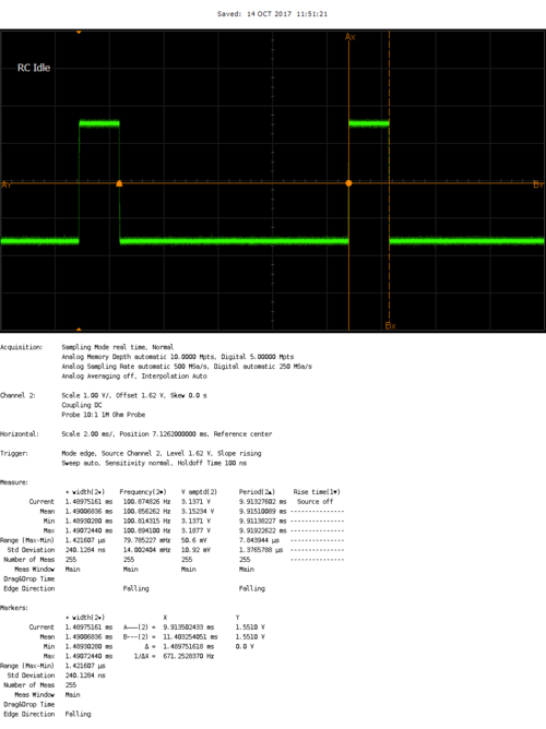
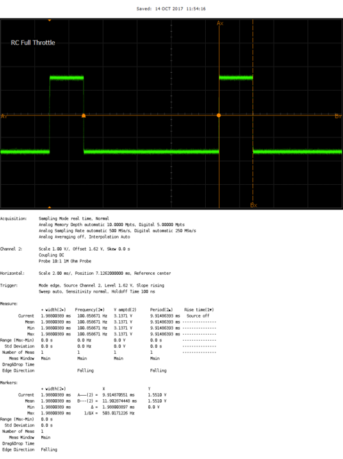
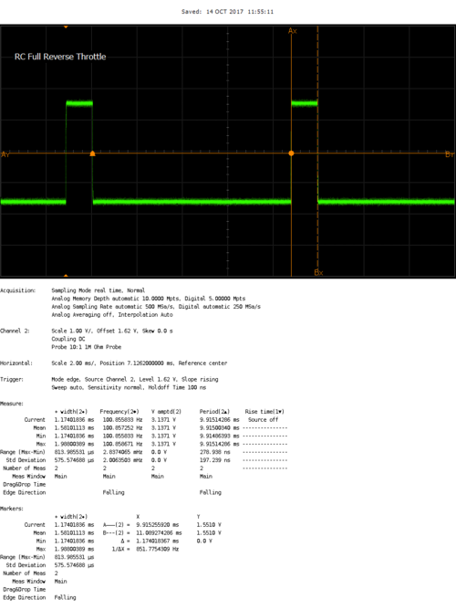
Then we tried implementing the same driving frequency on the SJ one board and we came across several issues:
1. Even though we were setting the SJ Board to 100Hz frequency, for some reason it was outputting ~110Hz
2. The percentage duty cycle we set in the SJ One board FW, was not exactly the same percentage that was output to the pins
3. Due to the above issue in (2), we couldn’t control the car to the finest level of speeds, either it would be stopped or it would be racing down so we had come up with different plans
Our solution to the above problems were to overclock the ESC to ~420Hz where we could control the speed limits very finitely within the scope of the PWM driving frequency of the SJ One board. Below are the scope shots of the PWM driven by the SJ One board to control the ESC
Servo (to turn the front wheels)
The Servo also uses PWM as an input to control the direction of the wheels. SJ One board has a limitation where all PWM signals need to be driven at the same frequency. Which means that as we are driving the ESC signals at ~420 Hz, we also had to drive the servo PWM signals at 420Hz. We had to do a parametric search of various PWM percentages to find out which ones would be best suited for turning the servos. Below are the scope shots of the PWM signals that SJOne board is using to drive the servo directions.
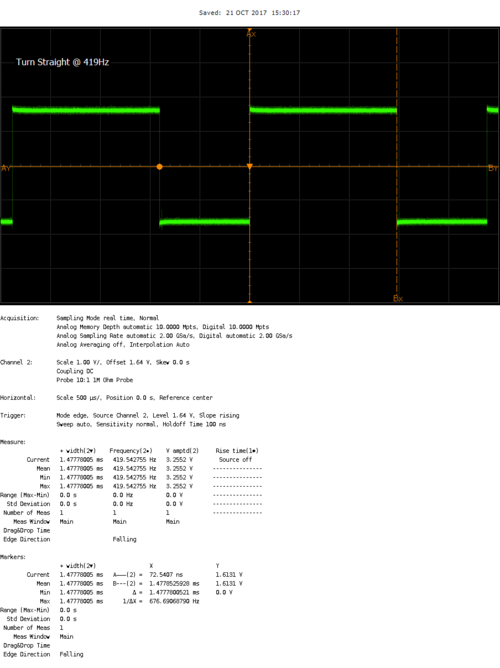
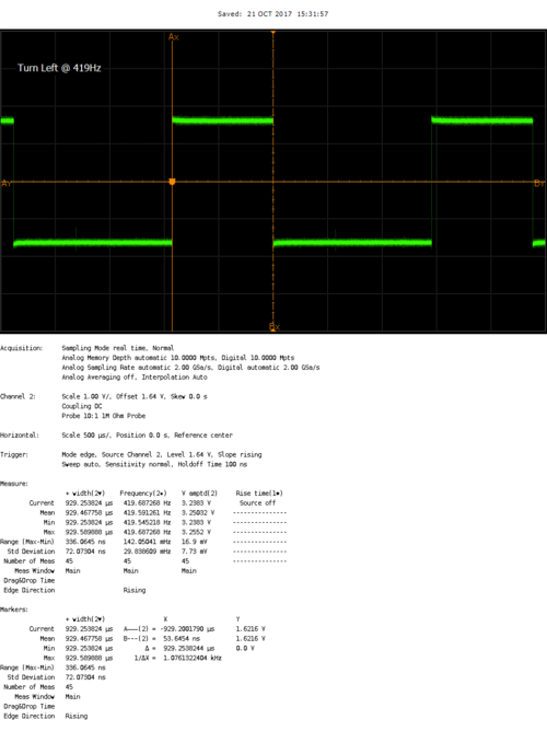
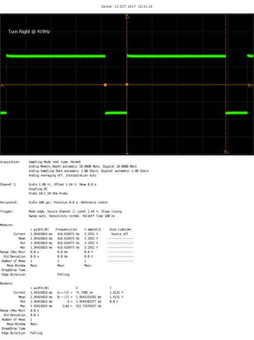
RPM Sensor (for detecting speed)
We used Traxxas RPM sensor (6520) to detect the speed. The package came with a single magnet which, along with the RPM sensor, needed to be mounted inside the motor compartment. The idea is that everytime the motor completes 1 whole revolution, it reaches very close to the sensor. And when the sensor detects the magnet nearby, it sends out a high pulse until the magnet moves away from it. Therefore, upon detecting the X number of rising edge in Y seconds we can say that there were X revolutions/Y seconds
The schematic for hooking up the RPM sensor was challenging because of the following:
- First we came across an issue where we were able to mount the magnet on the motor but it wasn't possible to mount the RPM sensor head inside the motor compartment. Later we found out that we needed a special compartment designed by Traxxas to hold the RPM sensor inside the motor compartment
- When we were prototyping the RPM sensor on breadboard, we saw that regardless of whether we bring the magnet close to the sensor or not, the signal voltage was always high. After many researches and trail and errors we found out that the signal pin had to be connected to the VCC across a 1K resistor so that it can effectively pull it down when it detects the magnet
- The Traxxas RPM sensor package came with a single magnet and a Hall effect sensor. So we put the single magnet inside the motor compartment and it was working fine when we were manually bring the hall effect sensor close by. But when we would put the motor cover on, we would see that the RPM sensor would never trigger. We fixed the issue by putting 2 magnets on top of each other to increase the magnetic field and then we were able to see the RPM sensor work seamlessly.
Hardware Interface
- CAN bus
- Motor ECU uses can1 to communicate with other ECUs. Motor primarily receives data from Master/Gateway to maneuver left/straight/right and also stop/forward/reverse the wheels. Motor also receives non-critical system data from Geographical ECU which needs to be displayed to the LCD. For the CAN configuration, we used baud rate of 100bps.
- PWM to Motor and servo
- There are 3 PWM pins available on SJ One Board. As explained earlier, all PWM frequencies were set to 420Hz. The Motor PWM PIN is driven from XXX and the servo PWM pin is driven from YYY.
- RPM sensor for edge detection
- The RPM input is connected to P2.6. It should be noted that there's a 1K resistor between the VCC of the RPM and the Signal Input
- Motor, Servo and the RPM share the power directly from the 8.4V Traxxas battery
- UART to LCD
- LCD uses UART TX/RX port to talk to the LCD. The UART is configured at 9600 bauds/sec.
Software Design
1. Initialization sequence
In the Motor ECU's init sequence we do the following in order:
- CAN Init
- Motor CAN is initialized on can1 with BAUD rate 100bps and TX/RX queue sizes of 100. Then the filter is setup for 100-150 MSG IDs.
- PWM Init
- 2 PWMs are set at P2.0 and P2.1 at 420Hz for Motor and Servo respectively. By default, the PWMs are set to straighten up the front wheels and put the back wheels to IDLE
- LCD Init
- UART is initialized at TXD2/RXD2 for LCD at 9600 baud rate
- RPM sensor Init
- P2.6 PIN is initialized as input with pull down resistor and a rising edge interrupt is being installed to detect the RPM triggers
2. 1 Hz Task
1Hz task is responsible for:
- CAN Bus reset logic
- In this handler we simply check if the CAN bus is off or not. If it's off, we do a BUS reset
- Handle Manual PWM (only in debug mode)
- This mode is only for debugging purpose. Just by change of a #define flag, we can shutdown all CAN related code and turn on the manual mode where we can use the on board switches to control the front and the back wheels. This has been a very effective was of debugging to find out HW related issues without taking off any of the components.
- RPM check
- We count the number of ticks that happened in 1 sec and reset the value of the ticks, therefore we get a revolution/second value
- Speed check
- We have predefined macros of what should be a high speed value and a low speed value. If we detect the current speed values are not in limit, we upshift or downshift the gears to control the speed
- Update LCD
- We get the following data and update them to the LCDs:
- RPM data
- Bearing data
- Compass data
- Send CAN messages
- We send CAN messages to Gateway with our current speed values
3. 10 Hz task
10Hz task is responsible for:
- Reverse State machine
- In order to reverse properly, we have to follow a specific sequences of Stop and Reverse. This handler takes care of it. Details of this state machine is described below in Bugs section
4. 100 Hz task
- Handle CAN messages
- This is the master handler for receiving all the CAN messages. Primarily they are motor CMDs from Gateway and compass data from Geographical for displaying on LCD.
Implementation
- Overall
- The Motor ECU's main task is to make sure the motor wheels and the servo turns are always in accordance to Master ECU's commandment. Motor ECU dequeues CAN messages in 100Hz task therefore the reaction time of wheels movement is never over 10ms. Although to reach full speed from stop, and more importantly, brake from full speed, it would take the car more than ~1s due to the weight and the inertia from speed.
- Debug mode
- In order to debug the motor side easily on the field we implemented a debug mode where we shut down all CAN communications and let the on board switches to control the front and the back wheels. In this mode, all the other peripherals like LCD ad RPM sensors are fully functional.
LCD
Sophia Quan
The uLCD-32PTU is a 3.2" (240x320) LCD screen with a micro SD connector, GPIO's along with I2C and serial COMMS. Workshop4 IDE was used to program the GUI, and data was transmitted from the SJOne board through UART communication. The LCD displays RPM clicks, GPS heading, bearing, distance, and also the current firmware version and branch name.
Note: The display here shows the angularmeter which will display the rpm, the top right box will display the bearing, heading, and distance from the GPS, and the bottom box will disply the firmware git hash, and branch.
Software Implementation
A software abstraction layer was implemented for the LCD screen consisting of init, ack/nack, and write functions.
- INIT
Since this LCD uses UART for its communication protocol, we set the baudrate at 9600bps and define the sizes of the rx/tx buffers.
- ACK & NACK
When sending data to the LCD screen, if data is successfully transmitted, the LCD screen will return a 0x06H, and if not transmitted properly, the LCD will return a 0x15H. The function to check ACK/NACK will check for these values and print to the console the proper debug message.
- WRITE
The data sent to the LCD screen is in a specified format for each object as shown below:
Angularmeter: BYTE0 - Event byte BYTE1 - Object type BYTE2 - Object index BYTE3 - Data byte 1 BYTE4 - Data byte 2 BYTE5 - Check sum
Static String Text Box: BYTE0 - Event byte BYTE1 - Object type BYTE2 - Object index BYTE3 - Data length BYTE4 - First character to be sent . . . BYTEN+4 - Last character to be sent BYTEN+5 - NULL character BYTEN+6 - Checksum
Sensors
Jason Tran and Rob Nikfar
The primary responsibility of the sensor ECU is to provide object detection capabilities.
Hardware Design
For object detection, distance sensors are used to provide proximity awareness. 3 distance sensors are placed on the front of the car (front left, front, and front right) to continuously measure the distance of the general directions. An object or obstacle can be detected when the distance of a given direction is below a threshold which indicates that the car cannot traverse in that direction and should attempt steer away from the blocked path.
Hardware Interface
Note: Despite the names, the TX and RX pins do not function as asynchronous serial transmit and receive in the implementation above. The TX functions as a digital output that drives the line high for a short duration when the sensor wants to trigger a cascaded sensor. The RX functions as an digital input that acts as a trigger for the sensor to begin measuring a distance.
Software Design
The sensor software follows a modular design pattern. Sensors is the top level module that contains periodic function definitions. The CAN Interface module consists of a periodic task that is responsible for broadcasting the most up to date sensor readings over CAN. The Car Proximity module also consists of several periodic tasks that are responsible for managing the frontal sensor readings.
Implementation
At 100Hz, the ECU reads the analog voltage of all 3 sensors, performs scaling on the raw ADC values to decode the voltage into inches, then stores the value in 3 circular buffers respectively. A circular buffer represents a history of inches reported by a sensor; the most recent firmware version stores the 3 most recent sensor readings into a circular buffer which represents a 30ms time frame.
At 10Hz, the ECU broadcasts the distance of all 3 sensors over CAN.
Filtering is also applied against the circular buffers. Of the data in a given circular buffer, the ECU reports the minimum distance.
There are 3 onboard LEDs that represent the state of the 3 frontal sensors. The LEDs are driven by GPIO. If, for example, the front sensor detects an object, then the ECU will assert the center onboard LED.
Geographical Controller
Yuyu Chen
The main purpose of the geographical controller is to guide the car towards its destination. This is done by processing data from the GPS and Compass module in order to get the Heading, Bearing, and Distance.
The compass will allow the user to calculate the Heading, which tells us which direction the car is pointing relative to magnetic north or simply, "Which way the car is pointing"?
The GPS will allow the user to get the current coordinate of the car, which will be useful when calculating the Bearing and Distance.
The Bearing tells us the direction from the current location to a checkpoint coordinate, and is given as the angle between the location and the current location of the car.
The Distance tells us how many meters away the current checkpoint is. Essentially, How far away are we from our destination?
The geographical controller is also responsible for:
1. Process data from GPS and Compass module.
2. Navigate to nearest checkpoints and to set destination.
3. Receive checkpoints from Bridge controller.
Hardware Design
Hardware Interface
CAN Bus
The CAN bus interface allows the geographical controller to send and receive data from other microcontrollers on the bus. For example, the geographical controller will send requests to the Gateway controller to tell it to turn right, left, or keep straight in order to reach the set checkpoints. The geographical controller will receive checkpoints from the Bridge controller in order for the geographical controller to know how to steer or how far away the destination is at.
MTK3339 Ultimate GPS
The MTK3339 Ultimate GPS module from Adafruit was chosen because it provided good results when it was used previously for a different project. The main purpose of the GPS module is to provide an accurate location of the car while the car navigates towards its destination. This is done by parsing NMEA sentences, which are transmitted by up to 22 satellites to pinpoint the current location of the module. There are various different types of NMEA sentences, such as $GPRMC and $GPGGA. The NMEA sentence that was used was $GPRMC, which provides only the recommended minimum. $GPRMC was also chosen because it is the only NMEA sentence the GPS module is able to provide data at 10Hz for real-time application. The module is interfaced via UART with a baud-rate set to 57600bps. The module also comes with a fix LED, which indicates if a GPS fix by blinking every 15 seconds, if not, it blinks every 1Hz. The module is powered by 3.3V from the SJOne board.
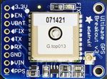
The $GPRMC sentence is separated by commas, which the user has to parse in order to get useful data out of the module. The most important data that the user want is the GPS coordinate, Latitude and Longitude. The strtok_r() function was used in order to parse the NMEA sentence.
Below is an example of a parsed $GPRMC sentence:
      Example: $GPRMC,225446,A,4916.45,N,12311.12,W,000.5,054.7,191194,020.3,E*68
                       1     2    3    4    5     6    7    8      9     10  11 12
| Number | Raw form | Description |
|---|---|---|
| 1 | 225446 | Time of fix 22:54:46 UTC |
| 2 | A | Navigation receiver warning A = OK, V = warning |
| 3 | 4916.45 | Latitude 49 deg. 16.45 min |
| 4 | N | North |
| 5 | 12311.12 | Longitude 123 deg. 11.12 min |
| 6 | W | West |
| 7 | 000.5 | Speed over ground, Knots |
| 8 | 054.7 | Course Made Good, True |
| 9 | 191194 | Date of fix 19 November 1994 |
| 10 | 020.3 | Magnetic variation 20.3 deg |
| 11 | E | East |
| 12 | *68 | mandatory checksum |
CMPS11 - Tilt Compensated Compass Module
The CMPS11 - Tilt Compensated Compass module was chosen because it provides the heading value, which let the user know which way the car is facing relative to magnetic north. Not only does it provide heading, the module also has a 3-axis gyro and a 3-axis accelerometer to remove or neglect any errors while the module is tilted (going up or down a slope). Another compass module was considered before choosing this module because the old module had to be calibrated extensively in order for it to work properly. This module only needed to be calibrated one time in an environment free of magnetic interference. The heading was double-checked after the module was mounted onto the car.
The compass module is placed away from all other components of the car to minimize any magnetic interference from the motor, servo, sensors, and microcontrollers. Placing it in an environment where there is magnetic interference will cause incorrect reading of the heading and the car will navigate towards the wrong direction. The compass module is interfaced via I2C. It is powered on by 3.6-5V, but 3.3V works also.
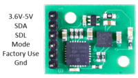
Software Design
The Geographical Controller is designed in a way so that the code is modular and organized. Only what is needed are exposed.
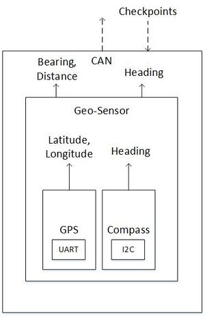
           GPS                                                 Compass                                                                Geo_Sensor
bool gps_init(gps_data_ready_cb cb);                  bool cmps11_init(void);                                                   bool geo_sensor_init(void);
bool get_lat_long(float *gps_data);                   float cmps11_get_heading(void);                                           void geo_sensor_run(void);
                                                      bool cmps11_calibrate(bool start_calibration, bool end_calibration);
The GPS library and Compass library are used by Geo_Sensor in order to calculate the Heading, Bearing, and Distance when geo_sensor_run() is called. Extern variables are used to share data between the CAN layer and Geo_Sensor.
extern float e_heading;
extern float e_bearing;
extern float e_distance;
extern float e_curr_latitude;
extern float e_curr_longitude;
extern float e_checkpoint_latitude;
extern float e_checkpoint_longitude;
extern uint8_t e_heading_valid;
extern bool e_gps_distance_valid;
| Task | Description |
|---|---|
| geo_init() | CAN_init()
geo_sensor_init() |
| geo_1Hz() | CAN_reset_bus() |
| geo_10Hz() | geo_sensor_run() command_car() |
| geo_100Hz() | can_rx() |
| geo_1kHz() | N/A |
Implementation
GPS
The GPS main purpose is to provide the latitude and longitude for its current location. It is interfaced via UART. This will help us calculate the bearing and distance to the destination. An example of raw NMEA string is provided in the Hardware Interface section of Geographical Controller.
Compass
The compass will provide the Heading, which tells us the direction where the car is facing. It is interfaced via I2C. The Heading value is in units of degree, from 0 degree to 360 degree. Only two registers are read (Hi and Lo) for heading value.
Register 2 & 3 are read to get the heading value
uint16_t heading = 0;
uint8_t heading_byte[2] = {0};
s_compass->readRegisters(CMPS11_ADDR, heading_16_bit_hi, &heading_byte[0], 2);
heading = heading_byte[0] << 8 | heading_byte[1];
There is a calibration sequence in order to initiate calibration mode.
3 separate I2C transactions are needed by first writing 0xF0 to Register 0, second write of 0xF5 to Register 0, and 0xF6 to Register 0.
After entering calibration mode, the module is needs to be rotated slowly on all axis to calibrate the magnetometer. After all the LED on the module stops blinking, place the module on all 6 sides to calibrate the accelerometer.
After calibrating the compass module, 0xF8 is written to Register 0 to end calibration mode.
Geo-Sensor
This layer combines the data from the GPS (latitude and longitude) and Compass (heading). In this layer, the distance (in meter) and bearing (in degree) are calculated. The distance and bearing are calculated by the current latitude and longitude, along with the checkpoint's latitude and longitude.
The Bearing (in degrees) is calculated from the following formula (Forward Azimuth):
   bearing = atan2( sin(longDiff_rad)*cos(lat2_rad), cos(lat1_rad)*sin(lat2_rad)-sin(lat1_rad)*cos(lat2_rad)*cos(longDiff_rad))
The distance (in meters) is calculated from the following formula (Haversine Formula):
a = sin^2(latDiff_rad/2) + cos(lat1_rad) * cos(lat2_rad) * sin^2(longDiff_rad/2)
   formula: c = 2 *atan2(sqrt(a), sqrt(1-a))
   d = Radius of Earth * c
The heading, bearing, and distance values are shared with the CAN layer for further manipulation. A simple moving average with a window of 10 was implemented to filter out bad GPS parsing (corrupt data) which occur after some time. Any distance value above the moving average will mark the GPS data as invalid and is dropped.
To navigate the car in the direction of the destination, the difference of the heading and bearing will have to be approximately zero. After many test runs, the team realize that the car moves to the right when the steering is straight. To account for this, the threshold for which to turn right is decreased so that it will turn right less.
Difference = Heading - Bearing
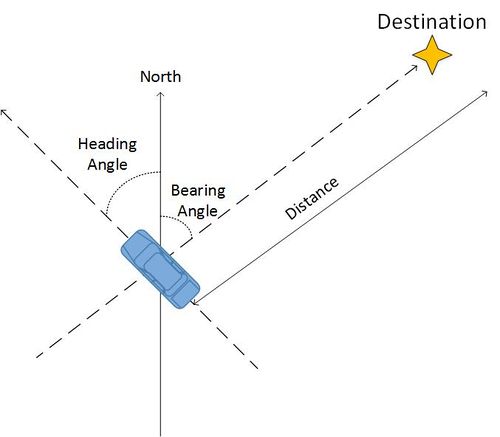
The difference between heading and bearing will tell us the offset between the direction of the current checkpoint and the current location of the car. It should steer the difference amount in order to go in direction of the checkpoint.
The distance to mark a checkpoint as reached is 5 meters radius from the actual destination, which accounts for some GPS inaccuracy. Therefore it will reach its destination within a 10 meter diameter. 5 meters was chosen after many test runs and seems to best fit because it does not over/under-shoot the checkpoint.
To receive checkpoints from the Bridge controller, the Bridge controller has to send the checkpoints via CAN to the Geographical controller. This is done with a handshake protocol between the two controllers. The Bridge will first send the number of checkpoints available to the Geographical controller. Once a non-zero number is received by the Geographical controller, the Geographical controller will start receiving Latitude and Longitude pairs from the Bridge controller. After receiving a "Done" signal from the Bridge, the Geographical controller responds with the number of Latitude and Longitude pair received. The handshake state machine for the Geographical controller is the left one above.
To command the car to navigate towards the destination, a GO signal needs to be sent from the Android App. To stop the car, a STOP signal is also sent from the Android App. After receiving checkpoints from the Bridge/App and Go is received, the Geographical controller will calculate which checkpoint is the closest based on distance between the checkpoints and the car's current location. After reaching that checkpoint, mark the checkpoint as "reached" to skip that checkpoint and find the next closest checkpoint until all checkpoint has been reached. The checkpoint algorithm for the Geographical controller is the right one above.
Bridge Controller
Marvin Flores & Yuyu Chen
The Bridge controller's main purpose is to act as a bridge between the Android Application and the car. The Android app is able to send and receive data wirelessly via Bluetooth. Any data, such as sensor data and current car location, can be sent to the bridge from other controllers via CAN. The Bridge controller will send the data wirelessly to the Android app to be displayed.
The main purpose of the Bridge Controller is to send checkpoints to the Geographical controller. This will be explained in the Implementation section of the Bridge Controller.
Hardware Interface
Since SJOne Board has an XBee interface, The Bluetooth XBee module was the easiest to interface with. A Bluetooth module is installed on the Bridge controller for communication between the SJOne board and the Android App. The Bluetooth module is interfaced via SJOne board's UART.
Software Design
In order to receive or send data, an additional command is added to the TerminalTask to handle Bluetooth Commands.
 //Pseudocode command handler, bluetoothMessage is an extern variable that is defined in the periodic_task bridge class
 if command == "signal go" -> bluetoothMessage.setGoSignal()
 else if command == "signal stop" -> bluetoothMessage.setStopSignal()
 else if command == "data_start" -> payloadSize = arg1
 else if command == "checkpoint" -> checkpoints[index].latitude = arg1, checkpoints[index].longitude = arg2
 else if command == "data_end" -> bluetoothMessage.setPayload(checkpoints, payloadSize)
Periodic Task Bridge class functions
| Task | Description |
|---|---|
| bridge_init() | CAN_init() |
| bridge_1Hz() | CAN_reset_bus() sendHeartbeat() - to Android App |
| bridge_10Hz() |
|
| bridge_100Hz() | can_rx() |
| bridge_1kHz() | N/A |
Implementation
A Bridge-Geo handshake was designed in order to send checkpoints to the Geographical controller. Checkpoints are received from the Android App after the "Checkpoints" button on the app is pressed. This will initiate sending the number of checkpoints to the Geographical controller. After sending the number of checkpoints, the Bridge will start sending checkpoints to the Geographical controller. After all checkpoints are sent, the Bridge will send a Done signal to the Geographical to notify it that it has finish sending checkpoints. After receiving a response with the correct number of checkpoints sent, the Bridge will be notified that the handshake is complete and "Go" can be pressed on the Android App. The state machine for the Bridge-Geo handshake is above.
Android Application
Marvin Flores
Main Tasks
- Generate checkpoints
- Send START and STOP commands
- Auto-connect to the Bridge module
- Display relevant information:
- map
- current phone location
- current car location
- connection heartbeat
- checkpoint
Software Design
High Level Architecture Design
The application's high level design is simple: Use Google Maps API to get the checkpoints and forward them to the bridge controller. Once the checkpoints are sent, the START command can be executed by clicking the START button on the app. This sends a start command signal to the bridge controller which then forwards the message to the Geo Controller via CAN bus. The STOP command, however, can be executed at any point in time and has the same process as the START command.
Implementation
Android applications follows the MVC pattern by default to allow developers to manage their applications easily. For this application, the Views are the MapView, Buttons, Heartbeat (ImageView), and TextViews to display extra information from the bridge. The Controller is the main fragment that contains all the logic. The Models are the data that come from the the Google Maps API and data coming from the bridge.
MapPane Fragment
The MapPane Fragment is used as the main class of the application and provides the link between the Models and the Logic of the application. MapPane Fragment contains the MapView, buttons for CHECKPOINTS, START, and STOP, as well as some extra information from the Bridge Controller such as heartbeat and sensor values.
Logic
The Logic resides in the MapPane Fragment and is a combination of different objects:
- Button Click Listeners - these listeners are attached to specific button views to execute methods when clicked.
- Message Handler - this handler is responsible for communication between the main fragment and the Bluetooth Service.
- Connection Watcher - this is a thread that runs at startup which monitors the connectivity with the Bridge Controller by checking the heartbeat message.
Bluetooth Service
This component is responsible for connecting/disconnecting with the Bridge Controller via Bluetooth. It's also responsible for sending/receiving data, as well as parsing the received data from the Bridge Controller.
MapHelper
This helper class is responsible of requesting a GET REST call to Google Maps API. It's also responsible of parsing the Json response and extract the checkpoints.
Use Cases
Auto Connect
The auto-connect feature happens right after the user opens up the application. During startup, the MapFragment sends a connect message to the MessageHandler. The MessageHandler of the BluetoothService receives it and calls the appropriate method on the BluetoothService. The method then initializes the ConnectThread class that handles the Bluetooth socket connection. Since the default Android's BluetoothListener only triggers once when gets disconnected, the author decided to create a custom Watcher to monitor the Bluetooth connection. This was done by checking the heartbeat coming from the Bridge Controller once connection is established. If the heartbeat message is lost for a given amount of time, the Watcher automatically reconnects to the bridge by resending the connect message from the MapPaneFragment.
Send Checkpoints
- User tap a location in the MapView.
- MapView has a click listener that initiates (with the help of MapHelper) a GET request to Google Maps API based on the phone location and the target location.
- The json response is then parsed and the checkpoints gets extracted, the target location and the checkpoints are now shown to the MapView.
- The user then clicks the CHECKPOINTS button
- Button Click Listener invokes a sendMessage that contains the checkpoints
- MessageHandler from the BluetoothService receives the message and forwards it to the ConnectThread.
- ConnectThread invokes ConnectedThread write function to send the message as bytestream to the Bridge Controller via Bluetooth. ConnectedThread gets initialized right after the connection is established.
- Once checkpoints are sent, the START/STOP command can be sent using similar process (without the MapHelper part).
Gateway/Master Controller
Rabeel Elahi
The Gateway/Master controller is one controller however, as the name suggests, it is responsible for two main functions:
- Gateway: Receiving, processing, and forwarding CAN messages to the respective nodes
- Master: Running object detection
Gateway
FullCAN Hardware Layer
The CAN controller can be driven by two principles known as BasicCAN or FullCAN. The advantage and disadvantages of both are listed below. The Gateway/Master utilizes FullCAN because the number of received messages were a finite number (< 10). However, the API has been designed to be scalable so more messages could be added if need be. Additionally, to minimize CPU usage by not polling for received messages in BasicCAN, FullCAN stores received messages into dedicated RX buffers without any CPU cycles.
--BasicCAN--
Pros
1. Not limited to a finite number of receive messages
Cons
1. One RX Buffer (FIFO)
2. FIFO management -- needs to be checked periodically
3. Received CAN identifier needs to compared with list of identifiers -- Time complexity: O(N)
4. Burden of message filtering
5. Messy Scalability
--FullCAN--
Pros
1. Set of dedicated RX buffers
2. Configured messages go straight to predefined section of CAN RAM – no CPU cycles required for transfer
3. Hardware filtering
4. Ability to check if a new message arrived
5. Clean Scalability
Cons
1. Limited to a finite number of received messages due to max 2k CAN RAM
Software Design
The goal of the IO layer is to make it straight and simple to add a new message to the gateway/master controller. After a new message has been added, the API automatically initializes FullCAN, adds the new message to FullCAN's hardware message filter, and takes care of either encoding or decoding the message periodically. High level layers can access the encoded or decoded data by simply calling the struct handle for the respective message.
The following steps briefly describes how the API accomplishes this:
1. Add the message to respective enum, TX or RX and extern the generated can struct handles (e.g., extern RPM_VALUE_CMD_t rpm)
2. In the struct array definition, with the enum index you just defined above, define the CAN message hex id and add the generated decode function to the respective function pointer array for the message
3. Add a struct getter function for the message in IO_CAN_gateway.c
4. Add IO_gateway_init and IO_gateway_run_100ms to your periodics
5. Call the struct handle to write or read data
Master
Object Detection
The object detection algorithm is a simple state machine. The input is ultrasonic data from the sensor controller and the outputs are motor commands to the motor controller.
Software Design
Implementation
1. Determine desired state based on ultrasonic data
  else if ((app_object_detection_getSensorData(APP_OBJECT_DETECTION_SENSOR_LEFT) >= app_object_detection_config.sensorThreshInInches) &&
  (app_object_detection_getSensorData(APP_OBJECT_DETECTION_SENSOR_RIGHT) >= app_object_detection_config.sensorThreshInInches) &&
  (app_object_detection_getSensorData(APP_OBJECT_DETECTION_SENSOR_FRONT) >= app_object_detection_config.sensorThreshInInches))
  {
  state = APP_OBJECT_DETECTION_STATE_ALL_CLEAR;
  }
2. if (currentState != desiredState)
- exitAction(currentState);
- entryAction(desiredState);
- currentState = desiredState;
4. Select motor parameters based on current state
- runAction(currentState);
 case APP_OBJECT_DETECTION_STATE_ALL_BLOCKED:
 app_object_detection_setMotorParameters(MOMENTUM_STOP, TURN_STRAIGHT);
 app_object_detection_data.reverseRequest = true;
 break;
--
SCons - Build Automation
Jason Tran
SCons is a build automation tool similar to Make and is based on the Python programming language. The 2 documents below describe the basic usage of SCons to build firmware and unit tests.
File:Cmpe243 f17 foxp2 SCons Build Automation.docx
File:Cmpe243 f17 foxp2 SCons Building Unit Tests.docx
Reference source code:
There are 3 build environments defined for the FoxP2 project.
1. ARM build environment
2. DBC build environment
3. Unit test build environment
ARM Build Environment
The ARM build environment utilizes the GNU ARM embedded toolchain to compile code for ARM targets namely for the SJOne Board's LPC1758 powered by an ARM Cortex-M3 (ARMv7-M architecture). Resources used by this build environment include Cortex-M3 specific code, FreeRTOS, start up code, linker scripts, LPC1758 drivers, and finally application-specific code. To build an ECU-specific program, an ECU name can be provided as a command line argument.
DBC Build Environment
The DBC build environment utilizes the default Python interpreter (defined in PATH) and the DBC parser Python tool to generate a C header file. The build environment uses the target ECU name as the target NODE required by the DBC parser.
Unit Test Build Environment
The unit test build environment utilizes the native C compiler on Linux hosts and Cygwin's C compiler on Windows hosts. SCons automatically searches for all unit tests source files in a test directory with file names starting with "test_". When the unit test flag is provided on command line, SCons will build then executed all unit tests. If any unit test fails, the overall SCons build will fail. For Windows, the FoxP2 repository contains pre-built shared libraries (.dll) of Cgreen unit testing library and Cygwin's POSIX references which are linked at run-time.
Validation and Testing Plan
Michael Jaradah and Taylor Kearns
Sensor Testing:
- Front left sensor detection (values)
- Front right sensor detection (values)
- Front middle sensor detection (values)
- Back left sensor detection (values)
- Back right sensor detection (values)
- Response & accuracy / precision
- put object 1 ft away, and make sure it reads 12 in (inches are sent over can)
- response to approaching obstacles (start from 3ft away and move in)
- LED correspondence with values
- All sensor MIA handling
Object Avoidance Testing:
- If right sensor blocked, go left
- If left sensor blocked, go right
- If front sensor blocked, reverse, go right/left
- If right & left sensor blocked, reverse, go right/left
- If back sensor blocked, move forward
- If back and front left blocked, go right
- If back and front right blocked, go left
Motor Testing:
- If ramped up, speed up
- If ramped down, slow down
- If no ramp, constant speed
LCD Testing:
- Display compass
- Display voltage
- Display speed
- Githash version
- Branch name
- All values update accordingly
- Display values MIA handling
Voltage sensor Testing:
- Compare smart device, voltmeter, and sensor readings
App Testing:
- Automatic car connection
- Set a GPS location
- Sends stop to car until destination chosen
- MIA car / GPS lock handling
Geographical testing:
- Losing the GPS Lock
- Accuracy in sending coordinates
- Location accuracy in chosing destination
- MIA GPS sensor
Basic Hardware Testing:
- Confirm switch to turn on car works
- 7-Seg value indication
- LED indications
- No loose / flimsy wires
- Car doesn't move unless given a GPS coordinate
- Avoids obstacles while moving towards a target destination
- Can reverse away from obstacles and continue towards the destination
- Avoid GPS when reversing for 5 seconds
Testing & Technical Challenges
- Integration testing on Pull requests to Master branch
- We had a very strict rule in our project where any pull request to master branch had to be checked independently by the Testing team before its approved for merging. The challenging part was that, even though thanks to SCons all the ECU codes were residing in one workspace, we had compile and burn the FW image 5 times separately on each boards and do testing against each and every one of the testing criteria. We limited this effort by making anther rule that there could only be a single PR in a day so that the testing team can efficiently check each PRs against their testing criteria and confirm that the PR is safe. This routine was extremely helpful in the integration and helped us immensely by making sure that there was not a single instance where our code build or functionality was ever broken!
- Ultrasonic sensors being extremely sensitive to temperature
- Throughout our integration testing we were surprised to see that the Ultrasonic sensors were extremely sensitive to external temperatures. As we approached our demo day, which also means the cold weather was slowly invading us, we saw increasingly erroneous behavior from our ultrasonic sensors. Luckily we were able to get around it by putting mounts around the sensors which made the sensors somewhat less sensitive to cold. Another option for us was to use the LIDAR but were skeptical to do that as we knew that Lidar was extremely power hungry and it would be sensitive to sunlight, especially when our demo would be in an early morning where the sunshine would possibly be shining directly to the LIDARs.
Bugs/Issues
ESC Initialization sequence
The Electronic speed control (ESC) unit is driven by PWM input signals and are pretty sensitive to the timings. We faced an issue where the ESC would keep blinking green LED which means that it can't detect the input signals even though the SJ One board is connected to the ESC driving the PWM signals. After a lot of scoping we found out that when the ESC is turned ON, its important that the SJ One baord has to send the same IDLE signature PWM to the ESC in order for it to detect the driver. Until this happens, the ESC will be in reset mode. Therefore, in our Init sequence for the SJ One board we made sure that upon start up, we send in the IDLE PWM sequence and then only we send other signals like forward, reverse, etc.
Reversing the ESC
During the initial stage of the system bring up we saw that even though we were putting the exact PWM frequency to the ESC to reverse, but for some reason it would never reverse. Through a lot of trial and error we found out that due to security reasons for protecting the motor from burning out when switching momentum at high speed, its intentionally designed to not reverse when the reverse signal comes while the motor is going forward. And hence we had to put a workaround where we created a state machine which will cycle through the following states when it will receive reverse command fro gateway:
- Stop
- Reverse
- Stop
- Reverse
At the 4th cycle of the state machine it would start reversing. But the challenging part was that we had to cycle through these states with a gap of 100ms or so and it was not possible to simply put a delay in the tasks as the task would take 500ms and would be over run. Instead we implemented a circular ping mechanism where we would change the state machine from the 10Hz callback and cycle through the state machines. It should be noted that during this 500ms, motor ECU ignores all other commands from Gateway. But as the car is sitting IDLE in this 500ms so motor doesn't expect Gateway to send any system critical CMD.
FullCAN Initialization
When generating FullCAN IDs, the SJ1 would crash when adding new messages. It wasn't initially clear as to why this was happening, but after taking some educated guesses it turned out that CAN IDs needed to be added to the FullCAN hardware filter starting from least to greatest.
Corrupt GPS NMEA sentences
After some time corrupt NMEA sentences would appear and give us erroneous values for latitude and longitude. Bad data will give us the wrong distance and bearing values. Since NMEA sentences have fixed formats and are delimited by commas, we know which data to pull out of the NMEA sentence. Rigorous unit testing has been done on the GPS module. But when its corrupt, the data becomes useless and should not be accounted for. Since the GPS is receiving data every 10Hz, the issue could be the UART baud rate. The issue is still unknown, but a filter has been set up to ignore any corrupt data. A Simple Moving Average with a window size of 10 was implemented to filter out any spike (corrupt data) on the calculated distance. Since we know that as the car gets closer to its destination, the distance decreases. If any data is above the moving average times some constant, the data is ignored.
Conclusion
This project gave us the opportunity to work on a system where multiple modules talk to each other and they all have critical duties which is required to get the whole system working. Our group had a mixture for experienced engineers who come from different industry backgrounds and we learnt so much from each other while being in an academic background. The thrilling experience of working on a self driving car and designing it from scratch was a huge accomplishment in this semester for all of us. At the beginning of the semester we were unsure of the challenges that we will be facing but now when we look back, we can see the tremendous amount of learning curve we had and of course all the lessons that we learnt from solving the issues and facing the challenges. Outside of the technical learning, we also learnt hands on about people and project management and was able to successfully implement Agile methodology in our development cycles. All these experiences are going to hep us tremendously in our future endeavors.
Project Video
FoxP2 Project Video
FoxP2 Demo Day Video
Project Source Code
Gitlab Android Application Repo
Lessons Learned
Design for Debug (DFD)
In our project we moved onto PCB very early in the project life cycle. While in one hand it gives the whole project a very cool look and reduces fly wire uses but at the same time it severely hinders HW debugging capability. For example, initially when the RPM sensor was tested on component level, it was very easy for us to characterize the behaviors by simple connecting the RPM sensor on a breadboard and using a scope with fly wires to observe the signals and their behaviors. But once the whole circuit moved onto the PCB, it was very hard to probe any of the signals without explicitly soldering fly wires onto the connections itself. There could be 3 ways to remdy this situation:
- Use either SJOne on board LEDs or external GPIO triggered LEDs on the customized PCB and use them as indication of signals. Limitation of this would be that the debugging will be limited to only SIGNAL_ON or SIGNAL_OFF not the actual values of the signal. For example, this method can not be used to debug a PWM frequency
- Use stacking header set with raised male pins (example of stacking header from Adafruit). The beauty of using this is that, at any given time, any of the SJ One on board pins can be scoped out without any interference! By far this would give us the best debugging capabilities possibly known to mankind in case of any HW issues. It would also give the flexibility to conenct a fly wire to any other pins at any given time without the need of soldering.
HW and FW reviews across the board
As the project went along we made rapid changes to our designs in both HW and FW. But these changes were sometimes sensitive to the whole system and caused hiccups here and there. It would have been a great idea if all the ECUs would do design reviews with all stake holders even though the others might not be directly related to those specific designs. Fr example, Motor ECU owner should create design document of the power and the ESC/Servo wiring and share with others especially when there's a major risk that Motor ECU combines the secondary 5V power and the Primary 8.2V Traxxas power through GND ref. Similarly the Sensor ECU owner would do design reviews on what sensors to use, how they differ and how they would be used with other stakeholders and so on.
Rigorous component level testing
Rigorous component level testing is something we could have improved in this project. For example, earlier in the development phase we could have done a parametric sweep of PWM frequency of the front wheels to see at what percentage of PWM, we can turn the wheels at what degree. Once that would have been documented, it would have been very easy for us to implement multiple angles of operation for the front wheels. Similarly, we could have done a parametric characterization of the ADC values for sensor readings vs a measured distances to see if the curve is really linear or there are some weird behavior when the distance increases drastically.
Second sourcing
Often times in the project, we would jump onto a component and will dive in to bring up the system but we completely overlooked the idea of what if we end up empty handed in the bring up process? For example, in our project we used Ultra sonic sensors for obstacle avoidance but we never had a backup plan, should we have failed to use the ultra sonic sensors effectively. In ideal scenario, we should have brought up Lidar lite system in parallel so any day if there would have been an issue with the ultra sonics, we would right away jump onto Plan B and get the Lidars on.
It would also be a great idea that whenever we get a component for the car, if it's not something very expensive, we need to buy couple of more extra pieces too. For example, when we bought the sensors, we bought exact amounts that we needed but once when the car crashed, we never had any extra ones so we had to wait for over night shipping to get more sensors. It would have been easily avoided if only we would have bought some extra pieces initially.
References
Acknowledgement
- Preetpal Kang for guiding us over our accomplishments
- Marvin Flores for the awesome 3D printed sensor mounts
- Western Digital Firmware Lab for letting us borrow the tools for electrical characterization and debugging
- Families for being patient while we spend weekends and weekday nights working on the car
References Used
- MCU: SJ One Board
- Base Code: Preet's BSP FW
- LCD: Genie User Guide
- ESC: Traxxas VXL ESC Guide
- Sensors: Ultrasonic sensor datasheet
- General: Google and Youtube
