Difference between revisions of "F18: Hit the Balloon"
Proj user15 (talk | contribs) (→Hardware Design) |
Proj user15 (talk | contribs) (→Hardware Interface) |
||
| Line 177: | Line 177: | ||
To begin this project, understanding the various pins on the input of the 16x32 RGB LED Matrix display is important in knowing how the display gets updated. The 16 and 32 indicate that the display has a total of 16 and 32 rows and columns, respectively. As mentioned above, there are 3 pins for row selection (A, B, C), 6 data pins (R1, G1, B1, R2, G2, B2), and 3 control pins (LAT, OE, and CLK). | To begin this project, understanding the various pins on the input of the 16x32 RGB LED Matrix display is important in knowing how the display gets updated. The 16 and 32 indicate that the display has a total of 16 and 32 rows and columns, respectively. As mentioned above, there are 3 pins for row selection (A, B, C), 6 data pins (R1, G1, B1, R2, G2, B2), and 3 control pins (LAT, OE, and CLK). | ||
| − | The 16x32 display is divided into two sections as shown in Figure | + | The 16x32 display is divided into two sections as shown in Figure 4, which is why the microcontroller needs to drive the top and bottom section of the display at the same time. |
| − | [[File:Rgb_display.jpg|thumb|500px|center|Figure | + | [[File:Rgb_display.jpg|thumb|500px|center|Figure 4: 16x32 LED Display Diagram]] |
To update the display, the output enable pin must be cleared. Then, on the rising edge of the clock, you can update a 32-bit shift register that is used to store data. Each corresponding bit [0:31] corresponds to the column on the display. Depending on if the bit is set in this register, will determine if you want that column of the LED to light up. When this register is updated, then you can toggle the clock bit. | To update the display, the output enable pin must be cleared. Then, on the rising edge of the clock, you can update a 32-bit shift register that is used to store data. Each corresponding bit [0:31] corresponds to the column on the display. Depending on if the bit is set in this register, will determine if you want that column of the LED to light up. When this register is updated, then you can toggle the clock bit. | ||
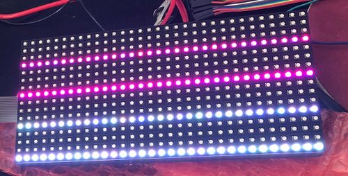
| − | After connecting the display with the SJOne board, you should see bright LEDs lighting up different rows as shown in Figure | + | After connecting the display with the SJOne board, you should see bright LEDs lighting up different rows as shown in Figure 5. After seeing this display, when you press on the wire to the input of the LED matrix, you will notice the LEDs on different rows will begin to flicker. |
| − | [[File:Board bringup.jpg|thumb|500px|center|Figure | + | [[File:Board bringup.jpg|thumb|500px|center|Figure 5: 16x32 LED Display Diagram]] |
Now that the board is powered up, we utilized Adafruit's display library ported the Arduino code to the SJOne LPC17XX microcontroller. | Now that the board is powered up, we utilized Adafruit's display library ported the Arduino code to the SJOne LPC17XX microcontroller. | ||
| Line 191: | Line 191: | ||
The first objective was to display a static screen, such as the start screen, on the display to learn how to manipulate the LEDs on the 16x32 matrix. A 16x32 two-dimensional array was created to indicate the color of a particular LED located on the matrix display. | The first objective was to display a static screen, such as the start screen, on the display to learn how to manipulate the LEDs on the 16x32 matrix. A 16x32 two-dimensional array was created to indicate the color of a particular LED located on the matrix display. | ||
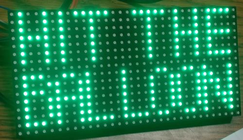
| − | [[File:Start static.jpg|thumb|500px|center|Figure | + | [[File:Start static.jpg|thumb|500px|center|Figure 6: Static Start Screen]] |
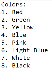
Following are the list of colors that are attainable by the LED | Following are the list of colors that are attainable by the LED | ||
Revision as of 02:50, 20 December 2018
Contents
Hit the Balloon
Abstract
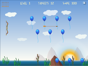
The objective of our project is to implement a game called "Hit the Balloon." Hit the Balloon is a game that has balloons that randomly spawns from the bottom of the screen to the top. There is a bow and arrow that moves vertically on the left side of the display. The player is able to control the vertical movement of the bow and shoot arrows at the balloons that are moving upward. When the arrow hits the balloons, the balloon object will be a hit. The objective of the game is to hit the maximum number of balloons with a limited number of arrows and time. At the end of the game, it will display the score, number of balloons the player hits. A screenshot of the "Hit the ballon" game that will be emulated is shown in Figure 1.
Objectives & Introduction
Team Members & Responsibilities
- Aaron Lee
- Arrow object(display, shoot, movement), testing, packaging, and report
- Rahul Kadam
- PCB, start/end screen, scoreboard, acceleration sensor, and testing
- Vijay Vanapalli
- Balloons, hit detection, and testing
Schedule
| Week# | Date | Task | Actual |
|---|---|---|---|
| 1 | 10/29 |
|
|
| 2 | 11/5 |
|
|
| 3 | 11/12 |
|
|
| 4 | 11/19 |
|
|
| 5 | 11/26 |
|
|
| 6 | 12/3 |
|
|
| 7 | 12/10 |
|
|
Parts List & Cost
| Item# | Part Description | Manufacturer | Qty | Cost |
|---|---|---|---|---|
| 1 | SJOne LPC1758 Microcontroller | Preet | 3 | $240.00 |
| 2 | Adafruit 16x32 RGB LED Matrix | Adafruit [1] | 3 | $75.00 |
| 3 | 5V/2A Power Supply Adapter | Amazon [2] | 2 | $11.99 |
| 4 | DC Power Connectors Socket 5.5mm x 2.1mm - Female | Amazon [3] | 10 | $6.99 |
| 5 | JLC PCB 5.5mm x 2.1mm - Female | JLC [4] | 10 | $20.00 |
Design & Implementation
The design section can go over your hardware and software design. Organize this section using sub-sections that go over your design and implementation.
Hardware Design
Discuss your hardware design here. Show detailed schematics, and the interface here.
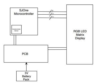
This project consists of using the SJOne microcontroller, 16x32 RGB LED display, and our custom PCB, used to power the microcontroller and the LED display. The system design of this project is shown below in Figure 2.
The first step after receiving all of the hardware was understanding how the RGB LED Matrix worked by reviewing AdaFruit's documentation [5], SparkFun's documentation [6], and watched a few youtube tutorials [7] to get the RGB LED Matrix and the SJOne microcontroller properly connected.
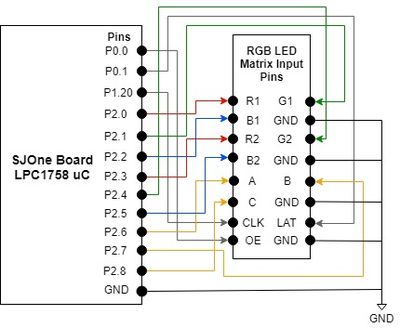
The connections for the RGB LED Matrix consist of six data pins (R1, G1, B1, R2, G2, B2), three control pins (CLK, Output Enable, Latch), three row-select pins (A, B, C), and four GND pins. The 5V/2A power supply connects to the backside of the LED matrix board. The ribbon cable that came with the Adafruit LED matrix was attached to the 'INPUT' connection on the backside of the LED matrix and the following connections were made to the SJOne microcontroller's GPIO pins using male-to-female wires. Please note that the ground connections from the SJOne board was connected to the ground of the LED Matrix and the power supply as shown in Figure 3. The SJOne microcontroller is also supplied power through USB or an external source.
If these connections are properly connected, the LED matrix should be on with the LEDs of random rows flashing. To test the LED Display, the AdaFruit Arduino library was used as a reference to port over the displaying of a design.
Hardware Interface
To begin this project, understanding the various pins on the input of the 16x32 RGB LED Matrix display is important in knowing how the display gets updated. The 16 and 32 indicate that the display has a total of 16 and 32 rows and columns, respectively. As mentioned above, there are 3 pins for row selection (A, B, C), 6 data pins (R1, G1, B1, R2, G2, B2), and 3 control pins (LAT, OE, and CLK).
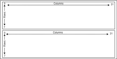
The 16x32 display is divided into two sections as shown in Figure 4, which is why the microcontroller needs to drive the top and bottom section of the display at the same time.
To update the display, the output enable pin must be cleared. Then, on the rising edge of the clock, you can update a 32-bit shift register that is used to store data. Each corresponding bit [0:31] corresponds to the column on the display. Depending on if the bit is set in this register, will determine if you want that column of the LED to light up. When this register is updated, then you can toggle the clock bit.
After connecting the display with the SJOne board, you should see bright LEDs lighting up different rows as shown in Figure 5. After seeing this display, when you press on the wire to the input of the LED matrix, you will notice the LEDs on different rows will begin to flicker.
Now that the board is powered up, we utilized Adafruit's display library ported the Arduino code to the SJOne LPC17XX microcontroller.
The first objective was to display a static screen, such as the start screen, on the display to learn how to manipulate the LEDs on the 16x32 matrix. A 16x32 two-dimensional array was created to indicate the color of a particular LED located on the matrix display.
Following are the list of colors that are attainable by the LED
Software Design
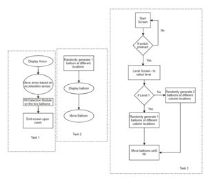
The following diagram elaborates on the flow chart that each task follows. The project is designed primarily on tasks handling different modules of the project viz, Balloon movements, level selector, hit detection and so on. The main two types of objects are arrows and balloons although by default they are of the same object type and simply have different parameter declarations. The input for the system includes the movements picked up by the onboard acceleration sensor and the button press from the player.Scores are kept throughout the session of the game and are updated accordingly.
Three tasks were created with same priority for the game design.
- In Task 3: This contains the actual game design i.e Start Screen, Game Screen, End Screen and Level Screen. Where, End Screen and Game Screen show scores : Game Screen updates the score live on hit, whereas the End Screen simply shows the players final score.
- In Task 2: This task is in the suspended state till the user selects a level as two. This is where the difficulty of the game increases, where 2 balloons are generated randomly - thus making it difficult for the user to aim or to score.
- In Task 3: This task is where the arrow object is being generated and controlled using the switch and acceleration sensor, where switch is used to shoot the arrow and the acceleration sensor move the arrow up and down. The important task in Task 1 is the hit detection, where we are continuously monitoring the arrow's row and column and balloon's row and column - upon which the decision is made and the score is updated.
RGB LED Matrix
The API detailed in the following flowchart, is a function that is committed towards generating the center of the object and holding its respective dimensions. Another function called display Object is tasked with drawing the object on the LED matrix.
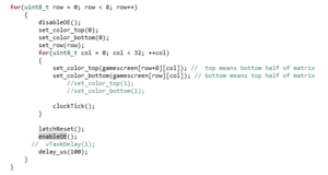
Below is a snippet of printing out the shape of the balloon, keeping its dimensions in mind. Essentially the display is updated with the object after iterating through each pixel in the matrix, with the exception of the specified boundaries of the object in question
The challenging part of the moving object design was to ensure how the object was to be shown drifting downward or upward in a smooth way. By design the LED Matrix sets color in sets of 8 rows as can be deciphered from the attached code snippet. More of the problem and how it was tackled is elaborated in the Testing.
Implementation
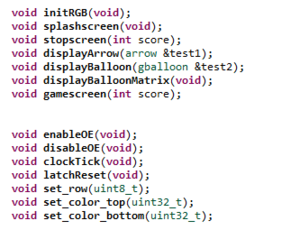
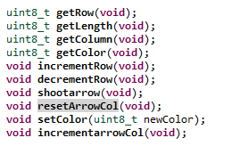
All the functions used are enlisted in the following class. Moreover, these are to be considered with the tasks in main that are dedicated towards the different background screens of the game itself from Start to the Final Score screen.
The game consists of a single player navigating through different levels (currently implemented two levels with varying number of balloons).
PCB Design
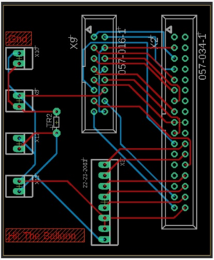
The Printed Circuit Board design was done using Eagle PCB editor which is a free open-source software for students. The software design tool enables designers to seamlessly connect schematic diagrams, component placement, PCB routing, comprehensive library content. The following components were used for designing the PCB.
PCB Parts List
| Quantity | Part |
|---|---|
| 1 | 34 pin female header to connect the SJOne board |
| 1 | 16 pin male header for the 16x32 RGB matrix |
| 1 | 8 pin male header to connect the external switch to the SJOne board & extra ground and Vcc pin |
| 1 | 100 ohm resistor |
| 1 | 2 pin power connector |
PCB design Issue
It is difficult to design a PCB without having components in hand because we are not able to set the exact drill size and component spacing. It was difficult to tune in our components because we were using EAGLE PCB autorouter to create traces and if the component orientation,placement and organisation is not proper the autorouter will not create 100% trace for you and then we have to manually create traces, in best case scenarios the autorouter can create vias between two connections.
Testing & Technical Challenges
Testing
For testing this project, each group member had their own individual setup consisting of LED Matrix display, SJOne Board, and development environment. Our approach to developing and designing this game was to make everything modular, where each person is given an object/feature to implement.
When we began the project and tested our code, it was easy to maintain because we started from scratch and didn't have a lot of code to control between the three of us. However, as we started adding more features into the game, the code began to get messier because we started to add sections from one person's code into another. Essentially, one thing that worked flawlessly without other tasks had turned into an issue when we integrated different objects and features together. The following issues are problems that we faced and this is what we would change if we attempted this again in the future.
Implementing multiple objects caused display to flicker/dimness in objects
Originally, our problem with this issue started when we had two objects in one task, the arrow and shooting arrow. To fix this issue, we separated these objects into multiple tasks. By doing this, we were able to make the display fluid and we were able to solve this issue between these two objects.
However, as the game design began to get more complex by introducing more objects with different logic (balloons, hit detection, scoreboard, and the start/end screen), we noticed that the issues with display flickering came back. We tried several methods to try and reduce/eliminate this problem but we weren't able to completely eliminate it from our project.
For future attempts, we would like to take the following approach to address this issue: Try a different method of displaying the objects. Currently, we have a task the position of the object and where the object should be and it will draw it onto the display. The problem with this was that the screen will keep on refreshing which is one reason we think can be the culprit to this issue. Instead of drawing one object in each task, we would like to try setting the LEDs/pixels on the display as a whole, then update/refresh the display.
Version Control
A problem that we encountered was not working on the same code baseline. At first, the thought process of having individual setups to develop and test is that it would be easier to work on tasks by ourselves and test from home when we needed to. We did not have to always meet up together to work on the code. As stated above, we didn't have too much problems at first, but as code got more complex, we encountered this issue. As we tried to put together code from each of our group members, there ended up being other changes that were made and was sent across the board. As a result, sometimes things worked as expected and sometimes they don't. Sometimes, the feature was only partially implemented and has not been fully tested or debugged with all the other features.
For future attempts, a solution to this would be to just work on one display and system which seems like the approach other groups took. This will eliminate any problems that we have between making updates and making sure that the quality of the code and display works flawlessly before implementing and adding more features altogether. Another approach to this problem can be splitting up the tasks with implementing the code, testing, and integrating with various parts. By taking this approach, the process should help in ensuring that the feature works a lot better and it can also help with discovering more bugs/features.
Balloon cross mid-section of display
The problem that we had with motioning of the balloon was when the the balloon crossed the mid-section of the LED matrix display from rows 7 to 8. We began implementing the balloon object by just using a single LED that incremented from the bottom of the display to the top. We were able to get the logic working well and had a seamless transition. Then, we started to make the balloons bigger to display. Rather than using the single LED to represent a balloon, we changed the design to a 3x3 LED. This was done by adding a height and width attribute for the balloon. By doing this, when the positioning of the balloon crossed row 6, it would we were not able to make it so that it transitioned from one-half of the screen to the other half. As an example, when it did reach that row, we would see that part of the balloon, 2x3 LEDs, will be shown on the bottom and the other part, 1x3 LEDs, will display at the very top of that screen.
For future attempts, we will need to spend some some time to debug the issue. We think it is due to the logic between incrementing/decrementing the balloons row position, display call for the balloon object, or the height/length attribute we have implemented for this class.
Conclusion
We learned that creating and integrating a system with the LED display is a difficult task to accomplish. For us, we ran into problems related to the display flickering, typically when the position value of an object changes (i.e. multiple balloons). We were able to make some features work at times, but after integrating different parts of the code between ourselves, we experienced these problems. Although we ran into these different issues, we did learn how a system can drive the output of a LED matrix display, such as a billboard, design/develop a PCB, and utilizing an OS for a game/system to handle different tasks. If we were to do this project over again, we would take a different approach on using a single and bigger display, and practice better testing/debugging on the integrated code. In the end, this was a fun project that provided a great learning experience and it was rewarding when features worked the way we wanted it to.
Project Video
PART 1 - LEVEL 1 PART 2 - LEVEL 2
Project Source Code
References
Acknowledgement
We would like to thank Preet and the ISA volunteers for providing valuable knowledge thats been passed on throughout this Fall semester. We've learned a lot by using the knowledge in a real-time application.
References Used
[1] AdaFruit's RGB Display Matrix Documentation
[2] Sparkfun's RGB Matrix Panel Explanlation
