Difference between revisions of "S18: XY-Plotter"
Proj user12 (talk | contribs) (→Objectives & Introduction) |
Proj user12 (talk | contribs) (→Project Video) |
||
| (410 intermediate revisions by the same user not shown) | |||
| Line 1: | Line 1: | ||
| − | == | + | == '''Project Title''' == |
| − | |||
| − | |||
| − | |||
| − | |||
| − | |||
| − | |||
| − | |||
| − | |||
| − | |||
| − | |||
| − | |||
| − | |||
XY-Plotter | XY-Plotter | ||
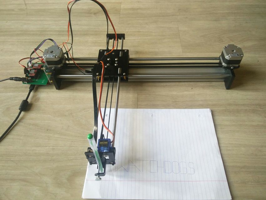
| + | [[File:Cmpe244_plotter_XY.jpg|850px|centre|thumb|'''Figure 1. Plotter Machine''']] <br> | ||
| − | == Abstract == | + | == '''Abstract''' == |
| − | + | We live in an epoch where the world is driven by technology. In recent decades, there have been so many advances in the field of technology. With this advancement for human upliftment, automation has become a paramount factor. This project aims at building a 2D XY-plotter which can efficiently draw 2D figures automatically. The plotter machine is assembled based on a mechanism similar to H-bot where the two stepper motors are on the main chassis connected to the single belt. Both the motors account for the movement of the chassis in X and Y axis and a servo motor is used to control the pen height. Gcode interpreter is developed in order to make the SJ one board decode the G-code and control the motors accordingly. Sd-card is used to provide the Gcode to the SJ one board. | |
| − | |||
| − | |||
| − | |||
| − | |||
| + | == '''Objectives & Introduction''' == | ||
| + | Computer numerical control (CNC) is the automation of machine tools by means of computers executing pre-programmed sequences of machine control commands. These machines find their use in any process that can be described as a series of movements and operations. These include 2D printing, laser cutting, welding, hole-punching etc. | ||
| + | XY plotter is a CNC(Computer Numerical Control) based drawing robot capable of drawing 2D figures. It uses LPC1758 ARM Cortex M3 based microcontroller(SJOne) as a brain of the robot. The SJOne board is interfaced to the motor shield PCB which connects two stepper and one servo motors. SD-card is selected to provide the 2D figures to the SJ one controller in the form of G-codes instructions. A G-code interpreter then decodes the instructions and generate the required movements for the stepper motor and servo motor. The home position for the plotter is specified using the limit switch. | ||
The objectives of the project are: | The objectives of the project are: | ||
* To learn FreeRTOS multitasking and demonstrate it. | * To learn FreeRTOS multitasking and demonstrate it. | ||
| − | * | + | * To acquire knowledge about intertask communication using queues. |
| − | * | + | * To become competent in implementing device drivers like GPIO, SPI, PWM. |
| − | * | + | * To make use of GPIO external interrupts and timer interrupt to connect with the limit switch. |
| − | * | + | * To understand software watchdogs and apply the same to the project. |
| + | * To learn mechanical aspects of rotating a motor through belts and pulleys. | ||
=== Team Members & Responsibilities === | === Team Members & Responsibilities === | ||
* Akshay Kurli | * Akshay Kurli | ||
| − | ** | + | ** Software Tasks Integration |
* Gaurav Yadav | * Gaurav Yadav | ||
| − | ** | + | ** Hardware Interface and software tasks integration |
| + | ** Bugs fixing | ||
* Pritam Gholap | * Pritam Gholap | ||
| − | ** | + | ** PCB design and Hardware testing |
* Tanmay Kishore Jambhekar | * Tanmay Kishore Jambhekar | ||
| − | ** | + | ** PCB design and Hardware testing |
| − | == Schedule == | + | == '''Schedule''' == |
| Line 49: | Line 39: | ||
! scope="col"| Task | ! scope="col"| Task | ||
! scope="col"| Actual | ! scope="col"| Actual | ||
| − | |||
|- | |- | ||
! scope="row"| 1 | ! scope="row"| 1 | ||
| Line 55: | Line 44: | ||
| | | | ||
* Research different mechanism for plotter assembling. | * Research different mechanism for plotter assembling. | ||
| − | * Requirement documentation.List out the parts required. | + | * Requirement documentation. List out the parts required. |
| Completed on 03/31 | | Completed on 03/31 | ||
|- | |- | ||
| Line 110: | Line 99: | ||
* Develop the interpreter task to read multi-line G-codes. | * Develop the interpreter task to read multi-line G-codes. | ||
* Establish communication between interpreter task and motor task. | * Establish communication between interpreter task and motor task. | ||
| − | | | + | | |
| + | * Completed on 05/09 | ||
| + | * Completed on 05/12 | ||
| + | * Completed on 05/17 | ||
| + | |- | ||
| + | ! scope="row"| 8 | ||
| + | | 05/15 | ||
| + | | | ||
| + | * Send board file for printing | ||
| + | * Create tasks to plot different characters | ||
| + | * Write the equation to draw lines at different angles | ||
| + | | | ||
| + | * Completed on 05/17 | ||
| + | * Completed on 05/18 | ||
| + | * Completed on 05/18 | ||
| + | |- | ||
| + | ! scope="row"| 9 | ||
| + | | 05/22 | ||
| + | | | ||
| + | * Test the PCB and integration of the full system | ||
| + | * Test the plotter for different characters and geometric figures | ||
| + | * Complete the Wiki Report | ||
| + | | | ||
| + | * Completed on 05/22 | ||
| + | * Completed on 05/22 | ||
| + | * Completed on 05/22 | ||
| + | |} | ||
| + | |||
| + | == '''Parts List & Cost''' == | ||
| + | |||
| + | {| class="wikitable" | ||
| + | |- | ||
| + | ! scope="col"| Item# | ||
| + | ! scope="col"| Part Desciption | ||
| + | ! scope="col"| Vendor | ||
| + | ! scope="col"| Qty | ||
| + | ! scope="col"| Cost | ||
| + | |- | ||
| + | ! scope="row"| 1 | ||
| + | | SJOne Boards | ||
| + | | From Preet | ||
| + | | 1 | ||
| + | | $80.00 | ||
| + | |- | ||
| + | ! scope="row"| 2 | ||
| + | | Nema-17 Stepper Motor | ||
| + | | Amazon | ||
| + | | 2 | ||
| + | | $28.00 | ||
| + | |- | ||
| + | ! scope="row"| 3 | ||
| + | | Micro Servo Motor 9G | ||
| + | | Amazon | ||
| + | | 1 | ||
| + | | $2.6 | ||
| + | |- | ||
| + | ! scope="row"| 4 | ||
| + | | GT2 Timing Belt and Pulley wheel | ||
| + | | Amazon | ||
| + | | 1 | ||
| + | | $14.99 | ||
| + | |- | ||
| + | ! scope="row"| 5 | ||
| + | | Allegro’s A4988 DMOS Microstepping Driver | ||
| + | | Amazon | ||
| + | | 2 | ||
| + | | $9 | ||
| + | |- | ||
| + | ! scope="row"|6 | ||
| + | | Limit Switch | ||
| + | | Amazon | ||
| + | | 2 | ||
| + | | $1 | ||
| + | |- | ||
| + | ! scope="row"| 7 | ||
| + | | XY-plotter chassis | ||
| + | | Amazon | ||
| + | | 1 | ||
| + | | $200 | ||
| + | |- | ||
| + | ! scope="row"| 8 | ||
| + | | Male and female pin connectors | ||
| + | | Excess solutions | ||
| + | | 4 (20 X 1) each | ||
| + | | $4 | ||
| + | |- | ||
| + | ! scope="row"| 8 | ||
| + | | IC 7805A Mouser Electronics | ||
| + | | Excess solutions | ||
| + | | 1 | ||
| + | | $0.58 | ||
|} | |} | ||
| − | == | + | == '''Design & Implementation''' == |
| − | + | Following sections provide the implementation of hardware and its design. The software provides the infrastructure to manage and control the hardware. | |
| + | |||
| + | === '''System Overview and Mechanism''' === | ||
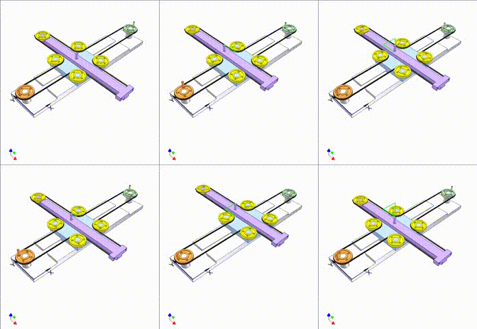
| + | The XY plotter machine is based on a mechanism similar to H-bot where the two motors responsible for XY movements are on the main chassis, which keeps the center of gravity closer to the chassis for a better stability. Graphic animation of the mechanism used in the project is shown in figure 2 where linear motions of the violet slider along X and Y axes are controlled by orange and green driving pulleys depicting two stepper motors. The violet slider has a pen connected at the front. | ||
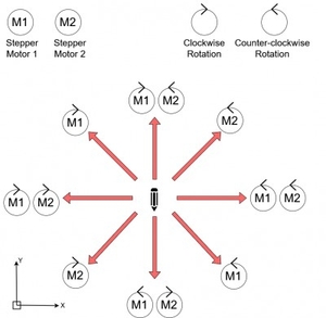
| + | The movement of pen based on the motor rotation is shown in figure 3. Based on the front view in figure 1, M1 and M2 represent two stepper motors on the left and right of the machine and the direction arrows shows the direction of the pen. For example to move the pen in the left direction on the X-axis, both the stepper motor should rotate in a clockwise direction with the same speed. | ||
| + | <center> | ||
| + | <table> | ||
| + | <tr> | ||
| + | <td> | ||
| + | <li style="display: inline-block;"> [[File:CMPE244_S18_H-bot_mechanism.gif|right|500px|thumb|'''Figure 2. Pen Slider movement mechanism''']] | ||
| + | </td> | ||
| + | <td> | ||
| + | </td> | ||
| + | <td> | ||
| + | <li style="display: inline-block;"> [[File:Cmpe244_S18_Pen_Movement.jpg|left|500px|thumb|'''Figure 3. Pen movement vs Motor Rotation''']] | ||
| + | </td> | ||
| + | </tr> | ||
| + | </table> | ||
| + | </center> | ||
| + | |||
| + | === '''Printed Circuit Board (PCB)''' === | ||
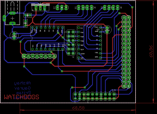
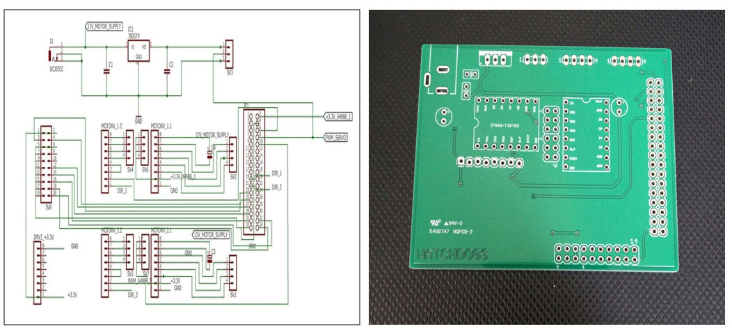
| + | PCB design is used to reduce the hardware complexity and complicated one-to-one wire connections. For this project, PCB designing was done using Autodesk's EAGLE 7.6.0. In this schematic of the board is done in which all the components are selected and general connections are done. After completing the schematics, it is converted to board file in which actual placement of components on board and routing of the signals is done. EAGLE provides features like auto routing, multilayer signal routing, converting the file specs in Gerber format for PCB printing and so on. | ||
| + | In this project, the board was designed for interfacing two motor drivers and one servo motor with SJOne board. Before concluding the design, all the components were placed on a breadboard and tested to check their functionality separately and then all together. After checking the hardware requirement and its availability, the board design was finalized. | ||
| + | The designed board consists of: | ||
| + | *Board size is 60.96 mm X 80.01 mm | ||
| + | *Voltage regulator to supply 5V to the servo motor and 3 pin connector for the same | ||
| + | *12V power supply for stepper motor | ||
| + | *Two motor drivers interfacing SJOne | ||
| + | *one 17 X 2, one 10 X 2 and one 8 X 1 pin connector for GPIO, 3.3V and GND from SJOne board | ||
| + | Track width for the signal is 0.016 mm and for the power signal, it is 0.024 mm. Package library of the A4988 driver was imported from the Sparkfun. The PCB design is then sent to PCB manufacturer with Gerber file. | ||
| + | <div><ul> | ||
| + | <li style="display: inline-block;"> [[File:Cmpe244_S18_Watchdog_PCB_board.png|center|1200px|thumb| '''Figure 4. PCB board layout''']] </li> | ||
| + | |||
| + | <li style="display: inline-block;"> [[File:CMPE244 S18 schemetic and actual PCB.png|center|1200px|thumb| '''Figure 5. PCB Schematic and Fabricated PCB ''']]</li> | ||
| + | </ul></div> | ||
| + | |||
| + | === '''Hardware Design''' === | ||
| + | |||
| + | [[File:Cmpe244_S18_Watchdogs_system_diagram.jpg|center|700px|thumb| '''Figure 6. Hardware Block Diagram''']] | ||
| + | |||
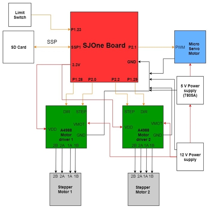
| + | This project consists of the following components: | ||
| + | * SJOne board: Main controller board. | ||
| + | * SD card: To store generated G code and retrieve for interpretation. Interfaced with SJOne board (SSP1). | ||
| + | * A4988 motor drivers: To control the motor revolution and direction using SJOne board. For step pins, GPIO P2.0 and P2.2 pins are used. For direction pins, GPIO P1.28 and P1.29 are used. | ||
| + | * Micro servo motor: To control the movement of the pen (up and down movement). For this, PWM pin P2.1 is used from SJOne board. | ||
| + | * Stepper motors: Bipolar stepper motor coils connected to A4988. | ||
| + | * 5V power supply: To step down the 12V supply to 5V for servo motor. | ||
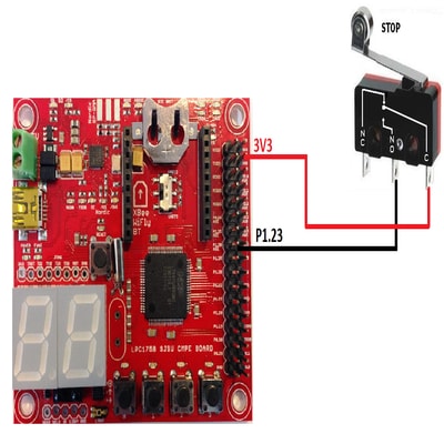
| + | * Limit switch: To place the plotter in its initial position. NC is kept open, NO pin to GPIO P1.23 and the common pin of switch is connected to 3.3V of SJOne board. | ||
| + | |||
| + | === '''Hardware Interface''' === | ||
| + | |||
| + | |||
| + | ==== GT2 Timing Belt and Pulley==== | ||
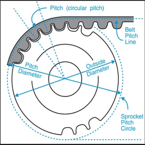
| + | A 2mm pitch and 6mm wide GT2 timing belt and pulley are used to transfer rotational motion (from a stepper motor) into linear motion (along with a rail). With the mechanism described above in figure 2, the two stepper motors on the main chassis are connected together with one GT2 belt with the help of two same-sized pulleys as shown in Figure 7. | ||
| + | |||
| + | [[File:CMPE244_S18_GT2_Timingbelt_and_Pulley.jpg|310px|thumb|center|'''Figure 7. Timing Belt and Pulley Alignment''']] | ||
| + | |||
| + | |||
| + | |||
| + | *Calculation: | ||
| + | Specification of the pulley used in this project is: | ||
| + | |||
| + | Number of teeth= 16; | ||
| + | |||
| + | Pitch = 2mm. | ||
| + | |||
| + | Therefore,as per the Figure 7 ,Circumference = pitch * number of teeth = 2 * 16 = 32mm. | ||
| + | |||
| + | ====A4988 Stepper Motor driver==== | ||
| + | |||
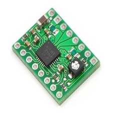
| + | A4988 stepper motor driver is DMOS microstepping driver with translator and overcurrent protection. This motor driver can supply up to 2A current per coil of the bipolar stepper motor. This driver requires the supply voltage of 3 - 5.5V. The motor supply voltage ranges from 8V to 35V depending upon the motors. These supplies should have appropriate decoupling capacitors close to the board, and they should be capable of delivering the expected currents. | ||
| + | |||
| + | Some of the key features of this driver are: | ||
| + | * Simple step and direction control interface | ||
| + | * Five different step resolutions: full-step, half-step, quarter-step, eighth-step, and sixteenth-step | ||
| + | * Adjustable current control to achieve higher step rates | ||
| + | * Over-temperature thermal shutdown, under voltage lockout and crossover current protection | ||
| + | * Short-to-ground and shorted-load protection | ||
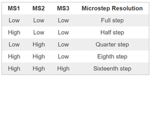
| + | The motor movement is generally controlled by two pins, i.e, STEP and DIR. These both pins are not pulled to any voltages internally and so both pins shouldn't be left floating. PWM signals are applied to STEP input in order to run the motors with selected step size. Now the selection of step size is also important which is done using MS1, MS2 and MS3 pins. Microstepping is important in order to achieve smoother and precise plotting. But it also draws more current than it takes in full step mode. | ||
| + | The reference voltage (VREF) is measured in order to keep the current supplied to coils within bound. | ||
| + | VREF = 8 ⋅ IMAX ⋅ RCS | ||
| + | where, IMAX is current limit and RCS is current sense resistance (0.068 Ω). | ||
| + | |||
| + | <div><ul> | ||
| + | <li style="display: inline-block;"> [[File:Cmpe244_ S18_Watchdogs_A4988_motor_driver.jpg|left|300px|thumb| '''Figure 8. A4988 stepper motor driver''']] </li> | ||
| + | <li style="display: inline-block;"> [[File:Cmpe244_S18_Watchdogs_microstep.jpg|right|300px|thumb|'''Figure 9. Configuration table for Microstepping''']] </li> | ||
| + | </ul></div> | ||
| + | |||
| + | ====NEMA 17 Stepper Motor==== | ||
| + | |||
| + | A stepper motor is one kind of electric motor used in the robotics industry, it converts electronic signals into mechanical movement each time an incoming pulse is applied to the motor. | ||
| + | Two NEMA 17 Stepper Motors are used to move the pen with the help of GT2 belt ad pulley discussed earlier. | ||
| + | Each pulse moves the shaft in fixed increments. Stepper motor used in the project has a 1.8° step resolution, and in order for the shaft to rotate one complete revolution, in full step operation, the stepper motor would need to receive 200 pulses, 360° ÷ 1.8 = 200. | ||
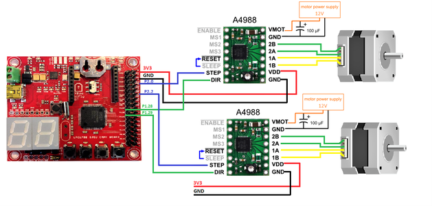
| + | Interfacing of the stepper motor to the SJone board is shown in figure 10. GPIO pins P2.0 and P2.2 are used to generate the pulses for the stepper motor at frequency 1Khz. | ||
| + | |||
| + | [[File:Cmpe244_S18_stepper_interface.png |center|1000px|thumb|'''Figure 10. Stepper Motor Interface''']] | ||
| + | |||
| + | *Calculation of steps: | ||
| + | The belt moves along the circumference of the pulley connected with the stepper motor shaft. | ||
| + | As per the figure 7 calculation, for one complete rotation of the stepper motor, the belt will move at a distance equivalent to 32mm. | ||
| + | i.e. 360° rotation = 32mm linear movement. | ||
| + | Therefore, one step which is equal to 1.8° will move the plotter by a distance of (32/360°)*1.8°= 0.16mm. Now, as an example, 100mm linear movement along X or Y axis would require 100/0.16 steps which are equal to 625 steps or pulses. | ||
| + | |||
| + | To achieve even fine resolution and smoother motion of the motors, half, quarter, eight, sixteenth step operation can be used with NEMA 17 stepper motors. | ||
| + | Micro-stepping increases number of steps per revolution by a factor of 2^n (where n is the micro-stepping factor). | ||
| + | |||
| + | For example half step n = 1/2, a single step will now become 1.8° * 2^(1/2) = 0.9, this doubles the number of required pulses.So a 100 mm line along X or Y axis will now require 1250 pulses. | ||
| + | |||
| + | ====Servo motor==== | ||
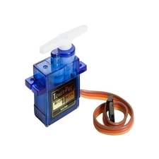
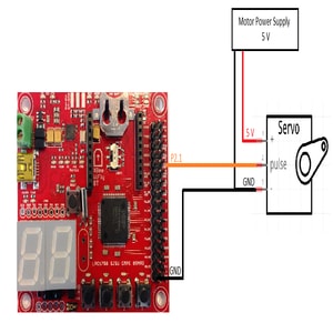
| + | Figure 11 and 12 shows the servo motor and interfacing it with the SJone board. | ||
| + | <center> | ||
| + | <table> | ||
| + | <tr> | ||
| + | <td> | ||
| + | <li style="display: inline-block;"> [[File:Cmpe244_S18_Watchdogs_Servo_motor.jpg|left|400px|thumb|'''Figure 11. Servo Motor''']] </li> | ||
| + | </td> | ||
| + | <td> | ||
| + | </td> | ||
| + | <td> | ||
| + | <li style="display: inline-block;"> [[File:Cmpe244_S18_servo_interfacing.jpg|right|300px|thumb|'''Figure 12. Servo Motor Interfacing with SJone''']] </li> | ||
| + | </td> | ||
| + | </tr> | ||
| + | </table> | ||
| + | </center> | ||
| + | |||
| + | |||
| + | The bracket holding the pen in place can be moved up and down vertically using a servo motor. This mimics picking up the pen during drawing or writing by hand. A SG90 9g digital servo motor is used for this. PWM output for the servo motor is given from pin P2.1. | ||
| + | For pen down, a PWM pulse of 1.5ms at 50 Hz, servo motor stays at the neutral position or 0°, the pen comes in contact with the surface and the plotter starts drawing. | ||
| + | For pen up, a PWM pulse of 2ms at 50Hz is input, servo motor rotates right. | ||
| + | |||
| + | ====Limit Switch==== | ||
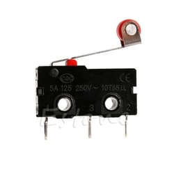
| + | Figure 13 shows the 250V 5A SPDT 1NO 1NC limit switch used in the project for defining the plotter home position. The plotter after finishing the drawing moves towards the home position till it encounters the limit switch placed at the starting position. It then generates an interrupt to the SJone board which disables the motion. The limit switch is used in a normally open mode as shown in figure 14. | ||
| + | <center> | ||
| + | <table> | ||
| + | <tr> | ||
| + | <td> | ||
| + | <li style="display: inline-block;"> [[File:Cmpe244_S18_limit_switch.jpg|600px|thumb|left|'''Figure 13. Limit Switch''']] <br> </li> | ||
| + | </td> | ||
| + | <td> | ||
| + | </td> | ||
| + | <td> | ||
| + | <li style="display: inline-block;"> [[File:CMPE244_S18_Limitswitch_interface.jpg|400px|thumb|right|'''Figure 14. Limit Switch Interface''']] <br> </li> | ||
| + | </td> | ||
| + | </tr> | ||
| + | </table> | ||
| + | </center> | ||
| + | |||
| + | == '''Software Design''' == | ||
| + | This section shows the software modules implemented to control the hardware interfaced with the SJone board. FreeRtos is used to handle the operations. Below are the three task developed. | ||
| + | * Parser Task: This task handles the parsing of the G-code instructions line by line and extracts the desired information. | ||
| + | * Motor Task: This task is used to control the stepper motor and servo motor according to the G-code instruction. | ||
| + | * Watchdog Task: This task monitors the above tasks for completion of Gcode. In case of inactivity of the above tasks, watchdog task force the plotter to move in a direction towards the home position. | ||
| + | |||
| + | ====Gcode==== | ||
| + | [https://en.wikipedia.org/wiki/G-code G-code](also RS-274), which has many variants is the common name for the most widely used numerical control (NC) programming language. It is used mainly in computer-aided manufacturing to control automated machine tools. It is a way to tell the machine on how to draw something in the form of very small incremental pieces of straight line, using which any type of figure can be made. As an instance, Gcode "G1" for linear interpolation is usually in the form of "G1 X150.00 Y200.00 F3500.00". Here, X, Y give the absolute distance/coordinates from the predefined origin, F3500.00 is the feed rate/speed in millimeters per seconds at which that coordinate point will be traveled towards. | ||
| + | Another G-code commonly used in the project is "M300 S30" and "M300 S50". "M300 S30" is used to signal pen should touch the drawing surface, and "M300 S50" for lifting the pen up both these tasks are performed by the servo motor moving the pen up and down. | ||
| + | "G4 P150" is used to pause everything for "P" amount of time in milliseconds, to let the servo motor complete its motion and make sure pen has moved to its final position before starting the stepper motors. | ||
| + | |||
| + | NCViewer is an online GCode visualized tool which was used in the project to make and visualize gcodes that will be interpreted by SJOne Board. Note that the lines visualized are all the paths that will be taken by the plotter to plot the word, this results in the display of paths that won't be actually be drawn by the plotter like those when the pen is in up position. | ||
| + | |||
| + | ====Parser Task==== | ||
| + | This task is created at low priority and is developed to parse and decode the G-code instructions. The desired values are stored in a struct command and are sent to the motor task via a FreeRtos queue. | ||
| + | |||
| + | |||
| + | <syntaxhighlight lang="c"> | ||
| + | typedef struct | ||
| + | { | ||
| + | char motion[8]; //motion type stored in a charcter array; | ||
| + | float x; // x axis coordinate value | ||
| + | float y; // y axis coordinate value | ||
| + | float feedrate; // feed rate value | ||
| + | float p; // wait time | ||
| + | float s; // pen up or down | ||
| + | } command; | ||
| + | |||
| + | </syntaxhighlight> | ||
| + | |||
| + | Code snippet for parsing the G-code file for G1, G4 and M300 for extracting the desired movement in a direction and distance is as shown below: | ||
| + | |||
| + | <syntaxhighlight lang="c"> | ||
| + | |||
| + | if (4 == sscanf(line.c_str(), "%s X%f Y%f F%f", motion.beg, &motion.x, &motion.y, &motion.feedrate)) | ||
| + | { | ||
| + | printf("motion is %s\n and x y f value is %f %f %f\n",motion.beg, motion.x,motion.y, motion.feedrate); | ||
| + | } | ||
| + | else if(2==sscanf(line.c_str(), "%s S%f", motion.beg, &motion.s)) | ||
| + | { | ||
| + | printf("motion is %s\n and S value is %f\n",motion.beg,motion.s); | ||
| + | } | ||
| + | else if(2==sscanf(line.c_str(), "%s P%f", motion.beg, &motion.p)) | ||
| + | { | ||
| + | printf("motion is %s\n and P value is %f\n",motion.beg,motion.p); | ||
| + | } | ||
| + | |||
| + | </syntaxhighlight> | ||
| + | |||
| + | |||
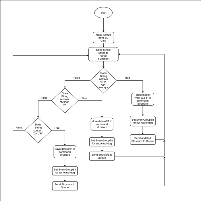
| + | Below is the flow of the parser task. | ||
| + | |||
| + | [[File:Cmpe244_S18_parserflowdiagram.jpg|1250px|thumb|center|'''Figure 15. Parser Task Flow''']] <br> | ||
| + | |||
| + | ====Motor Task==== | ||
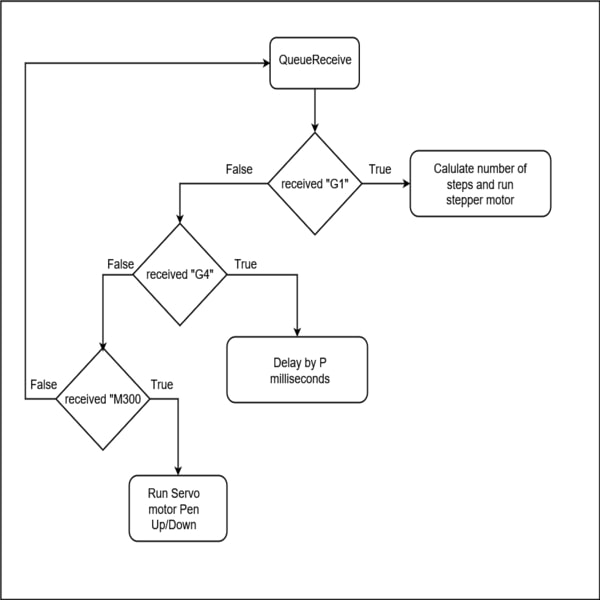
| + | This task is created at medium priority and developed to control the stepper or the servo motor according to the G-code instruction received over the queue. It checks for the G-code instruction and operates the plotter accordingly. Once the G-code struct is received, it verifies and extract the motion type and then calculates the steps for the movement along X or Y direction or diagonal movement. Below is the snippet where the motor task verifies the motion type for G1 and calculates the steps as per the coordinates received. | ||
| + | |||
| + | <syntaxhighlight lang="c"> | ||
| + | // Receives the structure from the parser task | ||
| + | if(xQueueReceive( Global_Queue_Handle, &( data_receive ), portMAX_DELAY )) | ||
| + | { | ||
| + | |||
| + | vTaskSuspend(xHandle); | ||
| + | |||
| + | printf("gcode received\n"); | ||
| + | string gcode__pwm(data_receive.motion); | ||
| + | if(gcode__pwm == "G1") | ||
| + | { | ||
| + | |||
| + | motion_x= data_receive.x- prev_x; | ||
| + | motion_y = data_receive.y- prev_y; | ||
| + | dist = sqrt(((data_receive.x - prev_x)*(data_receive.x - prev_x)) + ((data_receive.y - prev_y)*(data_receive.y - prev_y))); | ||
| + | /** | ||
| + | * This below 2 line calculates the steps for the linear motion | ||
| + | * Assigns the steps to x and y motor | ||
| + | */ | ||
| + | steps_x= abs(dist/0.16); | ||
| + | steps_y=abs(dist/0.16); | ||
| + | /** | ||
| + | * This code below in if statement test for the diagonal movement | ||
| + | * Calculates the steps for the motor for diagonal movement. | ||
| + | */ | ||
| + | |||
| + | if(abs(motion_x) == abs(motion_y)) | ||
| + | { | ||
| + | steps_d= abs(dist/0.113); | ||
| + | l_switch = 1; | ||
| + | } | ||
| + | } | ||
| + | } | ||
| + | </syntaxhighlight> | ||
| + | |||
| − | + | [[File:CMPE244S18_Motorflow.jpg|1250px|thumb|center|'''Figure 16. Motor Task Flow''']] <br> | |
| − | |||
| − | === | + | ====Watchdog Task==== |
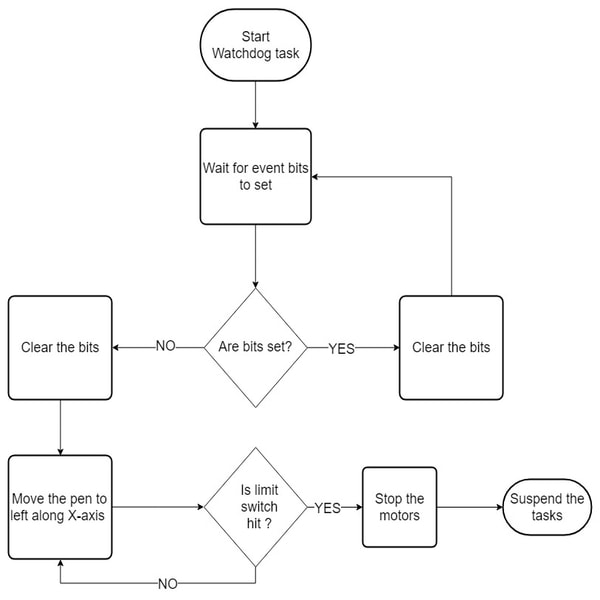
| − | + | This task monitors both the task for any inactivity and is defined at the highest priority. Inactivity signifies the end of the Gcode and watchdog task then force the plotter to move in a direction towards the home position. | |
| + | Below is the code snippet for watchdog task where in case of inactivity it calls the movehome() function. 2000 wait tick is used in the watchdog task after the rigorous testing of the plotter and finding the time to achieve the maximum distance. | ||
| − | = | + | <syntaxhighlight lang="c"> |
| − | |||
| − | = | + | uint32_t result = xEventGroupWaitBits(sw_watchdog,task_all_bits,pdTRUE,pdTRUE,2000); |
| − | |||
| − | == | + | if((result & task_all_bits)== task_all_bits) |
| − | + | { | |
| + | printf("Both the task working fine\n"); | ||
| + | } | ||
| + | else | ||
| + | { | ||
| − | + | if(!((result & cons_task_id)||(result & prod_task_id))) | |
| − | + | { | |
| − | + | printf("gcode is finished and now move towards the home position\n"); | |
| − | + | home.movehome(); // move the plotter towards home position | |
| + | } | ||
| − | + | } | |
| − | + | </syntaxhighlight> | |
| − | == | + | Below is the flow diagram of the watchdog chart. |
| − | + | [[File:CMPE244S18_Watchdog_flow.jpg|1250px|thumb|center|'''Figure 17. Watchdog Task Flow''']] <br> | |
| + | |||
| + | == '''Testing and Technical Challenges''' == | ||
| + | === Current calculation of motor === | ||
| + | * Stepper motor requires a minimum amount of current to run at a required frequency. | ||
| + | * High current is required for the stepper motor coils to rotate at a higher frequency say 1Khz. | ||
| + | * Vref=8*Imax*Rsc from the driver datasheet is used to find out the limiting current which is provided to the motor coils. The voltage Vref across the potentiometer was adjusted to ensure that the current is within the current limits of the motor as per the Nema-17 datasheet. | ||
| + | * For a full step configuration, Vref was adjusted to 0.7V. | ||
| + | |||
| + | === Erroneous movement of stepper motor using PWM pins output=== | ||
| + | * Stepper motors were initially interfaced with the PWM outputs. However, there was no accuracy of the number of steps taken by the stepper since it requires a precise timing control to stop it at a given step or position. | ||
| + | * Also, since all the PWM channels have the same frequency at a given time, therefore we had an issue providing different frequencies to the two stepper motors. | ||
| + | * In order to resolve aforementioned issues, GPIO was used to provide the accurate steps to the stepper motor. | ||
| + | |||
| + | === Task synchronization issue === | ||
| + | * Parser task was sending the next Gcode instruction on queue when the motor task was still performing the previous Gcode instruction due to the delay used in the motor task for running the stepper motor with GPIO. | ||
| + | * vTasksuspend was used to suspend the parser task when the queue item was received by the motor task. And was resumed after the motor task has completed the desired output from the instruction received. | ||
| + | |||
| + | === Different task for two Stepper Motor === | ||
| + | * Making an arc requires both the stepper motor to run on changing frequencies with steps. | ||
| + | * Therefore, two task was created initially for two different motors which could take the queue item from the parser task and run at their desired frequency accordingly. | ||
| + | * Above mechanism created a problem of jerking movement of the belt every time a task switch happens which resulted in wearing off the belt. | ||
| + | * A single task was created which could take the queue struct item from the parser task and run both the stepper motors. | ||
| + | |||
| + | === Issue with drawing arcs === | ||
| + | * The algorithm used for drawing the arc in the project resulted in an incorrect movement of the pen. | ||
| + | * Drawing arcs with the plotter require a perfect algorithm. | ||
| + | * Therefore, one possible solution is to use an algorithm like [https://en.wikipedia.org/wiki/Bresenham%27s_line_algorithm Bresenham algorithm] for circle and line. | ||
| + | |||
| + | === Manual height adjustment of the Pen === | ||
| + | * Pen height should be manually adjusted before plotter starts making the drawing. | ||
| + | * Incorrect height adjustment of the pen before the start will result in pen tip not touching the drawing sheet. | ||
| + | * An algorithm should be used which should automatically adjust the pen height. | ||
| + | |||
| + | === Size of the buffer to store G-code === | ||
| + | * A character array is used to store the G-code instruction from the Sd-card before the parser task starts decoding it. | ||
| + | * More number of lines in G-code will result in the bigger size of the buffer to store the G-code instructions. | ||
| + | |||
| + | === Placement of the limit switch === | ||
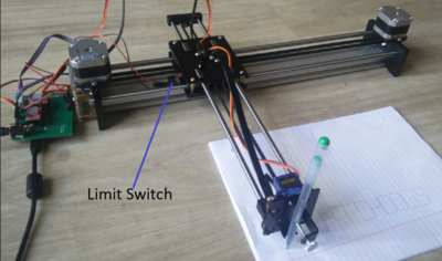
| + | * Limit switch is used to define the plotter home position where the watchdog task, after the G-code completion, forces the pen to move left towards the home and an interrupt is generated when the limit switch is pressed. | ||
| + | * Placement of the limit switch was difficult since it was placed on the chassis as shown below in figure 18. | ||
| + | |||
| + | [[File:CMPE244_S18_Limit_Switch_position.PNG|400px|thumb|center|''' Figure 18. Limit Switch Position ''']] | ||
| + | |||
| + | == '''Conclusion''' == | ||
| + | This project has been a great experience in a way where we learned different hardware interfacing with the SJone board. During the project period, we came across many challenges as discussed above and tried to solve the same. The plotter was able to make a 2D figure given from the sd card. Through this project, we have learned the followings: | ||
| + | * Application of GPIO and PWM to the motors. | ||
| + | * Interfacing SPI to read from SDcard. | ||
| + | * Make use of software watchdogs. | ||
| + | * Configuring interrupt for the limit switch. | ||
| + | * PCB designing. | ||
| + | * Mechanical aspects of rotating a motor through belts and pulleys. | ||
| + | * Use of FreeRtos API in a project. | ||
=== Project Video === | === Project Video === | ||
| − | + | * [https://youtu.be/9pdz0mTtlDQ XY_plotter video] | |
=== Project Source Code === | === Project Source Code === | ||
| − | * [https:// | + | * [http://socialledge.com/sjsu/index.php/File:CMPE244_S18_Watchdog_XY_Plotter.zip Zip File] |
| + | * [https://gitlab.com/gaurav12yadav/LPC1758_Plotter/tree/gaurav_branch Gitlab project link] | ||
| + | |||
| + | =='''References'''== | ||
| + | * [https://www.njr.com/semicon/PDF/NJM7800_E.pdf JRC 7805 datasheet] | ||
| + | * [https://www.pololu.com/file/0J450/a4988_DMOS_microstepping_driver_with_translator.pdf A4988 DMOS microstepping driver] | ||
| + | * [http://akizukidenshi.com/download/ds/towerpro/SG90.pdf SG90 Micro servo] | ||
| + | * [http://reprap.org/wiki/G-code Wiki page for G code interpretation] | ||
| + | * [https://learn.sparkfun.com/tutorials/tags/eagle PCB Development Tutorial] | ||
| + | * [https://ncviewer.com/ Ncviewer] | ||
| + | * Prof. Preet's video tutorials about FreeRTOS and lecture notes | ||
| − | |||
=== Acknowledgement === | === Acknowledgement === | ||
| − | + | We sincerely thank Prof. Preetpal Kang for giving us his guidance for this project. We also thank him for giving us this opportunity to explore our potential in executing project based on real-time operating systems. His valuable teachings based on industry experience have provided us with great knowledge about embedded systems. We also thank ISA team for solving our doubts and providing valuable information about same subject. | |
| − | |||
| − | |||
| − | |||
| − | |||
| − | |||
| − | |||
Latest revision as of 07:58, 27 May 2018
Contents
- 1 Project Title
- 2 Abstract
- 3 Objectives & Introduction
- 4 Schedule
- 5 Parts List & Cost
- 6 Design & Implementation
- 7 Software Design
- 8 Testing and Technical Challenges
- 8.1 Current calculation of motor
- 8.2 Erroneous movement of stepper motor using PWM pins output
- 8.3 Task synchronization issue
- 8.4 Different task for two Stepper Motor
- 8.5 Issue with drawing arcs
- 8.6 Manual height adjustment of the Pen
- 8.7 Size of the buffer to store G-code
- 8.8 Placement of the limit switch
- 9 Conclusion
- 10 References
Project Title
XY-Plotter
Abstract
We live in an epoch where the world is driven by technology. In recent decades, there have been so many advances in the field of technology. With this advancement for human upliftment, automation has become a paramount factor. This project aims at building a 2D XY-plotter which can efficiently draw 2D figures automatically. The plotter machine is assembled based on a mechanism similar to H-bot where the two stepper motors are on the main chassis connected to the single belt. Both the motors account for the movement of the chassis in X and Y axis and a servo motor is used to control the pen height. Gcode interpreter is developed in order to make the SJ one board decode the G-code and control the motors accordingly. Sd-card is used to provide the Gcode to the SJ one board.
Objectives & Introduction
Computer numerical control (CNC) is the automation of machine tools by means of computers executing pre-programmed sequences of machine control commands. These machines find their use in any process that can be described as a series of movements and operations. These include 2D printing, laser cutting, welding, hole-punching etc.
XY plotter is a CNC(Computer Numerical Control) based drawing robot capable of drawing 2D figures. It uses LPC1758 ARM Cortex M3 based microcontroller(SJOne) as a brain of the robot. The SJOne board is interfaced to the motor shield PCB which connects two stepper and one servo motors. SD-card is selected to provide the 2D figures to the SJ one controller in the form of G-codes instructions. A G-code interpreter then decodes the instructions and generate the required movements for the stepper motor and servo motor. The home position for the plotter is specified using the limit switch.
The objectives of the project are:
- To learn FreeRTOS multitasking and demonstrate it.
- To acquire knowledge about intertask communication using queues.
- To become competent in implementing device drivers like GPIO, SPI, PWM.
- To make use of GPIO external interrupts and timer interrupt to connect with the limit switch.
- To understand software watchdogs and apply the same to the project.
- To learn mechanical aspects of rotating a motor through belts and pulleys.
Team Members & Responsibilities
- Akshay Kurli
- Software Tasks Integration
- Gaurav Yadav
- Hardware Interface and software tasks integration
- Bugs fixing
- Pritam Gholap
- PCB design and Hardware testing
- Tanmay Kishore Jambhekar
- PCB design and Hardware testing
Schedule
| Week# | Date | Task | Actual |
|---|---|---|---|
| 1 | 03/27 |
|
Completed on 03/31 |
| 2 | 04/03 |
|
Completed on 04/08 |
| 3 | 04/10 |
|
|
| 4 | 04/17 |
|
|
| 5 | 04/24 |
|
|
| 6 | 05/01 |
|
|
| 7 | 05/08 |
|
|
| 8 | 05/15 |
|
|
| 9 | 05/22 |
|
|
Parts List & Cost
| Item# | Part Desciption | Vendor | Qty | Cost |
|---|---|---|---|---|
| 1 | SJOne Boards | From Preet | 1 | $80.00 |
| 2 | Nema-17 Stepper Motor | Amazon | 2 | $28.00 |
| 3 | Micro Servo Motor 9G | Amazon | 1 | $2.6 |
| 4 | GT2 Timing Belt and Pulley wheel | Amazon | 1 | $14.99 |
| 5 | Allegro’s A4988 DMOS Microstepping Driver | Amazon | 2 | $9 |
| 6 | Limit Switch | Amazon | 2 | $1 |
| 7 | XY-plotter chassis | Amazon | 1 | $200 |
| 8 | Male and female pin connectors | Excess solutions | 4 (20 X 1) each | $4 |
| 8 | IC 7805A Mouser Electronics | Excess solutions | 1 | $0.58 |
Design & Implementation
Following sections provide the implementation of hardware and its design. The software provides the infrastructure to manage and control the hardware.
System Overview and Mechanism
The XY plotter machine is based on a mechanism similar to H-bot where the two motors responsible for XY movements are on the main chassis, which keeps the center of gravity closer to the chassis for a better stability. Graphic animation of the mechanism used in the project is shown in figure 2 where linear motions of the violet slider along X and Y axes are controlled by orange and green driving pulleys depicting two stepper motors. The violet slider has a pen connected at the front. The movement of pen based on the motor rotation is shown in figure 3. Based on the front view in figure 1, M1 and M2 represent two stepper motors on the left and right of the machine and the direction arrows shows the direction of the pen. For example to move the pen in the left direction on the X-axis, both the stepper motor should rotate in a clockwise direction with the same speed.
|
|
|
Printed Circuit Board (PCB)
PCB design is used to reduce the hardware complexity and complicated one-to-one wire connections. For this project, PCB designing was done using Autodesk's EAGLE 7.6.0. In this schematic of the board is done in which all the components are selected and general connections are done. After completing the schematics, it is converted to board file in which actual placement of components on board and routing of the signals is done. EAGLE provides features like auto routing, multilayer signal routing, converting the file specs in Gerber format for PCB printing and so on. In this project, the board was designed for interfacing two motor drivers and one servo motor with SJOne board. Before concluding the design, all the components were placed on a breadboard and tested to check their functionality separately and then all together. After checking the hardware requirement and its availability, the board design was finalized. The designed board consists of:
- Board size is 60.96 mm X 80.01 mm
- Voltage regulator to supply 5V to the servo motor and 3 pin connector for the same
- 12V power supply for stepper motor
- Two motor drivers interfacing SJOne
- one 17 X 2, one 10 X 2 and one 8 X 1 pin connector for GPIO, 3.3V and GND from SJOne board
Track width for the signal is 0.016 mm and for the power signal, it is 0.024 mm. Package library of the A4988 driver was imported from the Sparkfun. The PCB design is then sent to PCB manufacturer with Gerber file.
Hardware Design
This project consists of the following components:
- SJOne board: Main controller board.
- SD card: To store generated G code and retrieve for interpretation. Interfaced with SJOne board (SSP1).
- A4988 motor drivers: To control the motor revolution and direction using SJOne board. For step pins, GPIO P2.0 and P2.2 pins are used. For direction pins, GPIO P1.28 and P1.29 are used.
- Micro servo motor: To control the movement of the pen (up and down movement). For this, PWM pin P2.1 is used from SJOne board.
- Stepper motors: Bipolar stepper motor coils connected to A4988.
- 5V power supply: To step down the 12V supply to 5V for servo motor.
- Limit switch: To place the plotter in its initial position. NC is kept open, NO pin to GPIO P1.23 and the common pin of switch is connected to 3.3V of SJOne board.
Hardware Interface
GT2 Timing Belt and Pulley
A 2mm pitch and 6mm wide GT2 timing belt and pulley are used to transfer rotational motion (from a stepper motor) into linear motion (along with a rail). With the mechanism described above in figure 2, the two stepper motors on the main chassis are connected together with one GT2 belt with the help of two same-sized pulleys as shown in Figure 7.
- Calculation:
Specification of the pulley used in this project is:
Number of teeth= 16;
Pitch = 2mm.
Therefore,as per the Figure 7 ,Circumference = pitch * number of teeth = 2 * 16 = 32mm.
A4988 Stepper Motor driver
A4988 stepper motor driver is DMOS microstepping driver with translator and overcurrent protection. This motor driver can supply up to 2A current per coil of the bipolar stepper motor. This driver requires the supply voltage of 3 - 5.5V. The motor supply voltage ranges from 8V to 35V depending upon the motors. These supplies should have appropriate decoupling capacitors close to the board, and they should be capable of delivering the expected currents.
Some of the key features of this driver are:
- Simple step and direction control interface
- Five different step resolutions: full-step, half-step, quarter-step, eighth-step, and sixteenth-step
- Adjustable current control to achieve higher step rates
- Over-temperature thermal shutdown, under voltage lockout and crossover current protection
- Short-to-ground and shorted-load protection
The motor movement is generally controlled by two pins, i.e, STEP and DIR. These both pins are not pulled to any voltages internally and so both pins shouldn't be left floating. PWM signals are applied to STEP input in order to run the motors with selected step size. Now the selection of step size is also important which is done using MS1, MS2 and MS3 pins. Microstepping is important in order to achieve smoother and precise plotting. But it also draws more current than it takes in full step mode. The reference voltage (VREF) is measured in order to keep the current supplied to coils within bound. VREF = 8 ⋅ IMAX ⋅ RCS where, IMAX is current limit and RCS is current sense resistance (0.068 Ω).
NEMA 17 Stepper Motor
A stepper motor is one kind of electric motor used in the robotics industry, it converts electronic signals into mechanical movement each time an incoming pulse is applied to the motor. Two NEMA 17 Stepper Motors are used to move the pen with the help of GT2 belt ad pulley discussed earlier. Each pulse moves the shaft in fixed increments. Stepper motor used in the project has a 1.8° step resolution, and in order for the shaft to rotate one complete revolution, in full step operation, the stepper motor would need to receive 200 pulses, 360° ÷ 1.8 = 200. Interfacing of the stepper motor to the SJone board is shown in figure 10. GPIO pins P2.0 and P2.2 are used to generate the pulses for the stepper motor at frequency 1Khz.
- Calculation of steps:
The belt moves along the circumference of the pulley connected with the stepper motor shaft. As per the figure 7 calculation, for one complete rotation of the stepper motor, the belt will move at a distance equivalent to 32mm. i.e. 360° rotation = 32mm linear movement. Therefore, one step which is equal to 1.8° will move the plotter by a distance of (32/360°)*1.8°= 0.16mm. Now, as an example, 100mm linear movement along X or Y axis would require 100/0.16 steps which are equal to 625 steps or pulses.
To achieve even fine resolution and smoother motion of the motors, half, quarter, eight, sixteenth step operation can be used with NEMA 17 stepper motors. Micro-stepping increases number of steps per revolution by a factor of 2^n (where n is the micro-stepping factor).
For example half step n = 1/2, a single step will now become 1.8° * 2^(1/2) = 0.9, this doubles the number of required pulses.So a 100 mm line along X or Y axis will now require 1250 pulses.
Servo motor
Figure 11 and 12 shows the servo motor and interfacing it with the SJone board.
|
|
|
The bracket holding the pen in place can be moved up and down vertically using a servo motor. This mimics picking up the pen during drawing or writing by hand. A SG90 9g digital servo motor is used for this. PWM output for the servo motor is given from pin P2.1.
For pen down, a PWM pulse of 1.5ms at 50 Hz, servo motor stays at the neutral position or 0°, the pen comes in contact with the surface and the plotter starts drawing.
For pen up, a PWM pulse of 2ms at 50Hz is input, servo motor rotates right.
Limit Switch
Figure 13 shows the 250V 5A SPDT 1NO 1NC limit switch used in the project for defining the plotter home position. The plotter after finishing the drawing moves towards the home position till it encounters the limit switch placed at the starting position. It then generates an interrupt to the SJone board which disables the motion. The limit switch is used in a normally open mode as shown in figure 14.
|
|
|
Software Design
This section shows the software modules implemented to control the hardware interfaced with the SJone board. FreeRtos is used to handle the operations. Below are the three task developed.
- Parser Task: This task handles the parsing of the G-code instructions line by line and extracts the desired information.
- Motor Task: This task is used to control the stepper motor and servo motor according to the G-code instruction.
- Watchdog Task: This task monitors the above tasks for completion of Gcode. In case of inactivity of the above tasks, watchdog task force the plotter to move in a direction towards the home position.
Gcode
G-code(also RS-274), which has many variants is the common name for the most widely used numerical control (NC) programming language. It is used mainly in computer-aided manufacturing to control automated machine tools. It is a way to tell the machine on how to draw something in the form of very small incremental pieces of straight line, using which any type of figure can be made. As an instance, Gcode "G1" for linear interpolation is usually in the form of "G1 X150.00 Y200.00 F3500.00". Here, X, Y give the absolute distance/coordinates from the predefined origin, F3500.00 is the feed rate/speed in millimeters per seconds at which that coordinate point will be traveled towards. Another G-code commonly used in the project is "M300 S30" and "M300 S50". "M300 S30" is used to signal pen should touch the drawing surface, and "M300 S50" for lifting the pen up both these tasks are performed by the servo motor moving the pen up and down. "G4 P150" is used to pause everything for "P" amount of time in milliseconds, to let the servo motor complete its motion and make sure pen has moved to its final position before starting the stepper motors.
NCViewer is an online GCode visualized tool which was used in the project to make and visualize gcodes that will be interpreted by SJOne Board. Note that the lines visualized are all the paths that will be taken by the plotter to plot the word, this results in the display of paths that won't be actually be drawn by the plotter like those when the pen is in up position.
Parser Task
This task is created at low priority and is developed to parse and decode the G-code instructions. The desired values are stored in a struct command and are sent to the motor task via a FreeRtos queue.
typedef struct
{
        char motion[8]; //motion type stored in a charcter array;
        float x;  // x axis coordinate value
        float y;  // y axis coordinate value
        float feedrate;  // feed rate value
        float p;    // wait time
        float s;    // pen up or down
} command;
Code snippet for parsing the G-code file for G1, G4 and M300 for extracting the desired movement in a direction and distance is as shown below:
                if (4 == sscanf(line.c_str(), "%s X%f Y%f F%f", motion.beg, &motion.x, &motion.y, &motion.feedrate))
                {
                    printf("motion is %s\n and x y f value is %f %f %f\n",motion.beg, motion.x,motion.y, motion.feedrate);
                }
                else if(2==sscanf(line.c_str(), "%s S%f", motion.beg, &motion.s))
                {
                    printf("motion is %s\n and S value is %f\n",motion.beg,motion.s);
                }
                else if(2==sscanf(line.c_str(), "%s P%f", motion.beg, &motion.p))
                {
                    printf("motion is %s\n and P value is %f\n",motion.beg,motion.p);
                }
Below is the flow of the parser task.
Motor Task
This task is created at medium priority and developed to control the stepper or the servo motor according to the G-code instruction received over the queue. It checks for the G-code instruction and operates the plotter accordingly. Once the G-code struct is received, it verifies and extract the motion type and then calculates the steps for the movement along X or Y direction or diagonal movement. Below is the snippet where the motor task verifies the motion type for G1 and calculates the steps as per the coordinates received.
// Receives the structure from the parser task
        if(xQueueReceive( Global_Queue_Handle, &( data_receive ), portMAX_DELAY ))
        {

            vTaskSuspend(xHandle);

            printf("gcode received\n");
            string gcode__pwm(data_receive.motion);
            if(gcode__pwm == "G1")
            {

                motion_x= data_receive.x- prev_x;
                motion_y = data_receive.y- prev_y;
                dist = sqrt(((data_receive.x - prev_x)*(data_receive.x - prev_x)) + ((data_receive.y - prev_y)*(data_receive.y - prev_y)));
                /**
                 * This  below 2 line calculates the steps for the linear motion
                 * Assigns the steps to x and y motor
                 */
                steps_x= abs(dist/0.16);
                steps_y=abs(dist/0.16);
                /**
                 * This code below in if statement test for the diagonal movement
                 * Calculates the steps for the motor for diagonal movement.
                 */

                if(abs(motion_x) == abs(motion_y))
                {
                    steps_d= abs(dist/0.113);
                    l_switch = 1;
                }
             }
         }
Watchdog Task
This task monitors both the task for any inactivity and is defined at the highest priority. Inactivity signifies the end of the Gcode and watchdog task then force the plotter to move in a direction towards the home position. Below is the code snippet for watchdog task where in case of inactivity it calls the movehome() function. 2000 wait tick is used in the watchdog task after the rigorous testing of the plotter and finding the time to achieve the maximum distance.
        uint32_t result = xEventGroupWaitBits(sw_watchdog,task_all_bits,pdTRUE,pdTRUE,2000);

        if((result & task_all_bits)== task_all_bits)
        {
            printf("Both the task working fine\n");
        }
        else
        {

            if(!((result & cons_task_id)||(result & prod_task_id)))
            {
               printf("gcode is finished and now move towards the home position\n");

               home.movehome(); // move the plotter towards home position
            }

        }
Below is the flow diagram of the watchdog chart.
Testing and Technical Challenges
Current calculation of motor
- Stepper motor requires a minimum amount of current to run at a required frequency.
- High current is required for the stepper motor coils to rotate at a higher frequency say 1Khz.
- Vref=8*Imax*Rsc from the driver datasheet is used to find out the limiting current which is provided to the motor coils. The voltage Vref across the potentiometer was adjusted to ensure that the current is within the current limits of the motor as per the Nema-17 datasheet.
- For a full step configuration, Vref was adjusted to 0.7V.
Erroneous movement of stepper motor using PWM pins output
- Stepper motors were initially interfaced with the PWM outputs. However, there was no accuracy of the number of steps taken by the stepper since it requires a precise timing control to stop it at a given step or position.
- Also, since all the PWM channels have the same frequency at a given time, therefore we had an issue providing different frequencies to the two stepper motors.
- In order to resolve aforementioned issues, GPIO was used to provide the accurate steps to the stepper motor.
Task synchronization issue
- Parser task was sending the next Gcode instruction on queue when the motor task was still performing the previous Gcode instruction due to the delay used in the motor task for running the stepper motor with GPIO.
- vTasksuspend was used to suspend the parser task when the queue item was received by the motor task. And was resumed after the motor task has completed the desired output from the instruction received.
Different task for two Stepper Motor
- Making an arc requires both the stepper motor to run on changing frequencies with steps.
- Therefore, two task was created initially for two different motors which could take the queue item from the parser task and run at their desired frequency accordingly.
- Above mechanism created a problem of jerking movement of the belt every time a task switch happens which resulted in wearing off the belt.
- A single task was created which could take the queue struct item from the parser task and run both the stepper motors.
Issue with drawing arcs
- The algorithm used for drawing the arc in the project resulted in an incorrect movement of the pen.
- Drawing arcs with the plotter require a perfect algorithm.
- Therefore, one possible solution is to use an algorithm like Bresenham algorithm for circle and line.
Manual height adjustment of the Pen
- Pen height should be manually adjusted before plotter starts making the drawing.
- Incorrect height adjustment of the pen before the start will result in pen tip not touching the drawing sheet.
- An algorithm should be used which should automatically adjust the pen height.
Size of the buffer to store G-code
- A character array is used to store the G-code instruction from the Sd-card before the parser task starts decoding it.
- More number of lines in G-code will result in the bigger size of the buffer to store the G-code instructions.
Placement of the limit switch
- Limit switch is used to define the plotter home position where the watchdog task, after the G-code completion, forces the pen to move left towards the home and an interrupt is generated when the limit switch is pressed.
- Placement of the limit switch was difficult since it was placed on the chassis as shown below in figure 18.
Conclusion
This project has been a great experience in a way where we learned different hardware interfacing with the SJone board. During the project period, we came across many challenges as discussed above and tried to solve the same. The plotter was able to make a 2D figure given from the sd card. Through this project, we have learned the followings:
- Application of GPIO and PWM to the motors.
- Interfacing SPI to read from SDcard.
- Make use of software watchdogs.
- Configuring interrupt for the limit switch.
- PCB designing.
- Mechanical aspects of rotating a motor through belts and pulleys.
- Use of FreeRtos API in a project.
Project Video
Project Source Code
References
- JRC 7805 datasheet
- A4988 DMOS microstepping driver
- SG90 Micro servo
- Wiki page for G code interpretation
- PCB Development Tutorial
- Ncviewer
- Prof. Preet's video tutorials about FreeRTOS and lecture notes
Acknowledgement
We sincerely thank Prof. Preetpal Kang for giving us his guidance for this project. We also thank him for giving us this opportunity to explore our potential in executing project based on real-time operating systems. His valuable teachings based on industry experience have provided us with great knowledge about embedded systems. We also thank ISA team for solving our doubts and providing valuable information about same subject.
